EP4350872A1 - Tab electrode plate and wound battery - Google Patents
Tab electrode plate and wound battery Download PDFInfo
- Publication number
- EP4350872A1 EP4350872A1 EP22810392.5A EP22810392A EP4350872A1 EP 4350872 A1 EP4350872 A1 EP 4350872A1 EP 22810392 A EP22810392 A EP 22810392A EP 4350872 A1 EP4350872 A1 EP 4350872A1
- Authority
- EP
- European Patent Office
- Prior art keywords
- angle
- tab plate
- tab
- tabs
- area
- Prior art date
- Legal status (The legal status is an assumption and is not a legal conclusion. Google has not performed a legal analysis and makes no representation as to the accuracy of the status listed.)
- Pending
Links
- 238000005192 partition Methods 0.000 claims abstract description 52
- 238000005520 cutting process Methods 0.000 claims abstract description 42
- 239000011248 coating agent Substances 0.000 claims abstract description 39
- 238000000576 coating method Methods 0.000 claims abstract description 39
- 230000001154 acute effect Effects 0.000 claims abstract description 18
- 239000011888 foil Substances 0.000 claims abstract description 17
- 238000004804 winding Methods 0.000 claims description 25
- 239000011149 active material Substances 0.000 description 16
- 238000010586 diagram Methods 0.000 description 11
- 238000005452 bending Methods 0.000 description 10
- 238000000034 method Methods 0.000 description 10
- 239000000843 powder Substances 0.000 description 5
- 238000005096 rolling process Methods 0.000 description 5
- 230000007704 transition Effects 0.000 description 5
- 230000015572 biosynthetic process Effects 0.000 description 4
- 238000005516 engineering process Methods 0.000 description 3
- 230000000295 complement effect Effects 0.000 description 2
- HBBGRARXTFLTSG-UHFFFAOYSA-N Lithium ion Chemical compound [Li+] HBBGRARXTFLTSG-UHFFFAOYSA-N 0.000 description 1
- 230000009286 beneficial effect Effects 0.000 description 1
- 230000000694 effects Effects 0.000 description 1
- YWXYYJSYQOXTPL-SLPGGIOYSA-N isosorbide mononitrate Chemical compound [O-][N+](=O)O[C@@H]1CO[C@@H]2[C@@H](O)CO[C@@H]21 YWXYYJSYQOXTPL-SLPGGIOYSA-N 0.000 description 1
- 238000003698 laser cutting Methods 0.000 description 1
- 229910001416 lithium ion Inorganic materials 0.000 description 1
- 238000004519 manufacturing process Methods 0.000 description 1
- 238000002360 preparation method Methods 0.000 description 1
Images


Classifications
-
- H—ELECTRICITY
- H01—ELECTRIC ELEMENTS
- H01M—PROCESSES OR MEANS, e.g. BATTERIES, FOR THE DIRECT CONVERSION OF CHEMICAL ENERGY INTO ELECTRICAL ENERGY
- H01M4/00—Electrodes
- H01M4/02—Electrodes composed of, or comprising, active material
- H01M4/13—Electrodes for accumulators with non-aqueous electrolyte, e.g. for lithium-accumulators; Processes of manufacture thereof
-
- H—ELECTRICITY
- H01—ELECTRIC ELEMENTS
- H01M—PROCESSES OR MEANS, e.g. BATTERIES, FOR THE DIRECT CONVERSION OF CHEMICAL ENERGY INTO ELECTRICAL ENERGY
- H01M10/00—Secondary cells; Manufacture thereof
- H01M10/04—Construction or manufacture in general
- H01M10/0431—Cells with wound or folded electrodes
-
- H—ELECTRICITY
- H01—ELECTRIC ELEMENTS
- H01M—PROCESSES OR MEANS, e.g. BATTERIES, FOR THE DIRECT CONVERSION OF CHEMICAL ENERGY INTO ELECTRICAL ENERGY
- H01M10/00—Secondary cells; Manufacture thereof
- H01M10/05—Accumulators with non-aqueous electrolyte
- H01M10/052—Li-accumulators
- H01M10/0525—Rocking-chair batteries, i.e. batteries with lithium insertion or intercalation in both electrodes; Lithium-ion batteries
-
- H—ELECTRICITY
- H01—ELECTRIC ELEMENTS
- H01M—PROCESSES OR MEANS, e.g. BATTERIES, FOR THE DIRECT CONVERSION OF CHEMICAL ENERGY INTO ELECTRICAL ENERGY
- H01M10/00—Secondary cells; Manufacture thereof
- H01M10/05—Accumulators with non-aqueous electrolyte
- H01M10/058—Construction or manufacture
- H01M10/0587—Construction or manufacture of accumulators having only wound construction elements, i.e. wound positive electrodes, wound negative electrodes and wound separators
-
- H—ELECTRICITY
- H01—ELECTRIC ELEMENTS
- H01M—PROCESSES OR MEANS, e.g. BATTERIES, FOR THE DIRECT CONVERSION OF CHEMICAL ENERGY INTO ELECTRICAL ENERGY
- H01M50/00—Constructional details or processes of manufacture of the non-active parts of electrochemical cells other than fuel cells, e.g. hybrid cells
- H01M50/50—Current conducting connections for cells or batteries
- H01M50/531—Electrode connections inside a battery casing
- H01M50/533—Electrode connections inside a battery casing characterised by the shape of the leads or tabs
-
- H—ELECTRICITY
- H01—ELECTRIC ELEMENTS
- H01M—PROCESSES OR MEANS, e.g. BATTERIES, FOR THE DIRECT CONVERSION OF CHEMICAL ENERGY INTO ELECTRICAL ENERGY
- H01M50/00—Constructional details or processes of manufacture of the non-active parts of electrochemical cells other than fuel cells, e.g. hybrid cells
- H01M50/50—Current conducting connections for cells or batteries
- H01M50/531—Electrode connections inside a battery casing
- H01M50/534—Electrode connections inside a battery casing characterised by the material of the leads or tabs
-
- H—ELECTRICITY
- H01—ELECTRIC ELEMENTS
- H01M—PROCESSES OR MEANS, e.g. BATTERIES, FOR THE DIRECT CONVERSION OF CHEMICAL ENERGY INTO ELECTRICAL ENERGY
- H01M50/00—Constructional details or processes of manufacture of the non-active parts of electrochemical cells other than fuel cells, e.g. hybrid cells
- H01M50/50—Current conducting connections for cells or batteries
- H01M50/531—Electrode connections inside a battery casing
- H01M50/538—Connection of several leads or tabs of wound or folded electrode stacks
-
- Y—GENERAL TAGGING OF NEW TECHNOLOGICAL DEVELOPMENTS; GENERAL TAGGING OF CROSS-SECTIONAL TECHNOLOGIES SPANNING OVER SEVERAL SECTIONS OF THE IPC; TECHNICAL SUBJECTS COVERED BY FORMER USPC CROSS-REFERENCE ART COLLECTIONS [XRACs] AND DIGESTS
- Y02—TECHNOLOGIES OR APPLICATIONS FOR MITIGATION OR ADAPTATION AGAINST CLIMATE CHANGE
- Y02E—REDUCTION OF GREENHOUSE GAS [GHG] EMISSIONS, RELATED TO ENERGY GENERATION, TRANSMISSION OR DISTRIBUTION
- Y02E60/00—Enabling technologies; Technologies with a potential or indirect contribution to GHG emissions mitigation
- Y02E60/10—Energy storage using batteries
-
- Y—GENERAL TAGGING OF NEW TECHNOLOGICAL DEVELOPMENTS; GENERAL TAGGING OF CROSS-SECTIONAL TECHNOLOGIES SPANNING OVER SEVERAL SECTIONS OF THE IPC; TECHNICAL SUBJECTS COVERED BY FORMER USPC CROSS-REFERENCE ART COLLECTIONS [XRACs] AND DIGESTS
- Y02—TECHNOLOGIES OR APPLICATIONS FOR MITIGATION OR ADAPTATION AGAINST CLIMATE CHANGE
- Y02P—CLIMATE CHANGE MITIGATION TECHNOLOGIES IN THE PRODUCTION OR PROCESSING OF GOODS
- Y02P70/00—Climate change mitigation technologies in the production process for final industrial or consumer products
- Y02P70/50—Manufacturing or production processes characterised by the final manufactured product
Definitions
- the present application relates to the technical field of battery technology, and in particular, to a tab plate and a wound battery.
- lithium-ion batteries have been widely used due to their high specific power, long cycle life, good safety performance, and pollution-free advantages.
- Traditional wound batteries are mainly single tab or multitab wound batteries, while full-tab wound batteries are increasingly recognized due to their low internal resistance and high energy density.
- the manufacturing method of full-tab wound batteries usually involves coating one end of the positive and negative electrode plates with active material (the part coated with active material is called the coating area), and leaving the other end as a blank part (the part uncoated with active material, which is called the empty foil area).
- the full-tab is formed by flattening the blank part.
- the object of the present application is to provide a tab plate and a wound battery, aiming to address the shortcomings of the background mentioned above.
- the angle a formed between the first side and the partition line is an acute angle
- the rolling pressure required to flatten the tabs can be reduced when the winding direction is the same as the acute angle a, thereby avoiding the deformation of the tab plate and reducing the falling off of the active materials from the positive and negative electrode plates, so as to greatly improve the yield rate of full-tab wound cells.
- the stress of bending the tabs can be reduced, thereby ensuring the quality of the wound battery.
- the cutting area is separated from the coating area through the reserved area, which can avoid cutting to the coating area during the formation of the tabs by cutting, so as to prevent the active material powder on the coating area from falling off, thereby avoiding the impact on the electrical performance of the tab plate and facilitating the cutting operation.
- the wound battery not only has a simple design, but also has good electrical performance, high yield rate, and strong practicality.
- An embodiment of the present application provides a tab plate, including a coating area and an empty foil area located on one side of the coating area.
- the empty foil area includes a cutting area and a reserved area.
- the reserved area is arranged close to the coating area and is located between the coating area and the cutting area.
- the cutting area is cut to form a plurality of tabs, wherein the plurality of tabs are arranged in sequence along a length direction of the tab plate, and ends of the plurality of tabs close to the coating area are connected together through the reserved area.
- a partition line is formed at a connection position between the cutting area and the reserved area.
- Each tab includes a first side and a second side which are oppositely arranged, and both the first side and the second side intersect with the partition line.
- An angle a is formed between the first side and the partition line, the angle a is located within the tab, and the angle a is an acute angle.
- the cutting area is cut to form a plurality of tabs in the present application refers to cutting the entire cutting area to form a plurality of tabs, or cutting the cutting area partially to form a plurality of tabs. As shown in FIG. 2 of the present application, the cutting area is partially cut to form a plurality of tabs.
- the bending or folding distance of each tab towards the central hole can be consistent or inconsistent; for example, it is possible to fold all tabs with the partition line as the folding line towards the central hole in order to have a uniform bending or folding distance; it is also possible to use the partition line as the folding line for some tabs, while other tabs use any position in the empty foil area as the folding line.
- the tab plate is a positive electrode tab plate and/or a negative electrode tab plate, and a winding direction of the tab plate is the same as an orientation of the angle a.
- a boundary line is formed at the connection position between the empty foil area and the coating area, and the distance between the partition line and the boundary line is less than or equal to 5 mm; or the distance between the partition line and the boundary line is greater than or equal to 0.5 mm and less than or equal to 5 mm; or a distance between the partition line and the boundary line is greater than or equal to 0.5 mm and less than or equal to 2 mm.
- the other angle formed between the first side and the partition line is b, the angle b is located outside the tab, and the angle b is rounded; and/or, an angle formed between the second side and the partition line is c, the angle c is located outside the tab, and the angle c is rounded.
- the intersection of the two sides after being rounded is a smooth transition, which is more conducive to reducing the pressure required to flatten the tabs.
- the other angle formed between the second side and the partition line is d, the angle d is located within the tab, the angle d is a right angle or obtuse angle, and the sum of the angle a and the angle d is less than or equal to 180°.
- a spacing between every two adjacent tabs there is a spacing between every two adjacent tabs, and a length of the spacing is 1/100-1 or 1/10-1/2 of a length of the tab.
- a radius of the rounded angle b is less than the length of the spacing, and a radius of the rounded angle c is less than the length of the spacing.
- the length of the spacing is 0.1 mm-10 mm; or 1 mm-4 mm; or 0.1 mm-1 mm; or 5 mm-8 mm.
- the angle a is less than 60°; or the angle a is less than 45°. This angle range is more conducive to reducing the pressure required to flatten the tabs.
- each tab further includes a third side, the third side intersects with both the first side and the second side, and the third side is arranged opposite to the partition line.
- An angle formed between the first side and the third side is rounded, and/or an angle formed between the second side and the third side is rounded.
- the intersection of the two sides after being rounded is a smooth transition, which is more conducive to reducing the pressure required to flatten the tabs and reducing tip discharge.
- the tab has a quadrilateral structure.
- the tab has a parallelogram structure.
- a ratio of the length to the width of each tab is (1-4):2, or (1-3):2, or 0.5:1.
- Another embodiment of the present application also provides a wound battery, including a positive electrode tab plate and a negative electrode tab plate, wherein the positive electrode tab plate and/or the negative electrode tab plate are/is the aforementioned tab plate.
- the wound battery further includes a first separator, and the first separator is sandwiched between the positive electrode tab plate and the negative electrode tab plate.
- the positive electrode tab plate, the first separator and the negative electrode tab plate are stacked and wound to form a battery cell.
- the tabs of the positive electrode tab plate and the tabs of the negative electrode tab plate are respectively located at both ends of the battery cell.
- a distance of the tabs of the positive electrode tab plate beyond a top end of the first separator after being flattened is 0.5-5 mm, and a distance of the tabs of the negative electrode tab plate beyond a bottom end of the first separator after being flattened is less than 5 mm.
- the tab plate provided in the present application sets the angle a formed between the first side of the tab and the partition line as an acute angle.
- the winding direction of the tab plate is consistent with the orientation of the acute angle.
- the cutting area is separated from the coating area through the reserved area, which can avoid cutting to the coating area during the formation of the tabs by cutting, so as to prevent the active material powder on the coating area from falling off, thereby avoiding the impact on the electrical performance of the tab plate and facilitating the cutting operation.
- the wound battery not only has a simple design, but also has good electrical performance, high yield rate, and strong practicality.
- an embodiment of the present application provides a tab plate 1, which, before being cut, includes a coating area 11 and an empty foil area 12 located on one side of the coating area 11.
- a boundary line 13 is formed at the connection position between the empty foil area 12 and the coating area 11.
- the tab plate 1 is a rectangular structure before being cut, with a length direction X and a width direction Y.
- the tab plate 1 is divided into a coating area 11 and an empty foil area 12, wherein the coating area 11 is coated with an active material (generally, the active material is in the form of powder), and the empty foil area 12 is not coated with the active material.
- the empty foil area 12 includes a cutting area 121 and a reserved area 122 (the reserved area 122 will not be cut), the reserved area 122 is arranged close to the coating area 11 and is located between the coating area 11 and the cutting area 121.
- the cutting area 121 is cut to form a plurality of tabs 14 of quadrilateral structure, and the plurality of tabs 14 are arranged in sequence along the length direction X of the tab plate 1.
- the ends of the plurality of tabs 14 close to the coating area 11 are connected together through the reserved area 122.
- a partition line 123 (the partition line 123 is represented by a dashed line in FIG. 1 ) is formed at the connection position between the cutting area 121 and the reserved area 122.
- Each tab 14 includes a first side 141 and a second side 142 which are oppositely arranged, and both the first side 141 and the second side 142 intersect with the partition line 123.
- An angle a is formed between the first side 141 and the partition line 123, the angle a is located within the tab 14, and the angle a is an acute angle.
- the tab plate 1 is a positive electrode tab plate 21 and/or a negative electrode tab plate 22 (the structures of the positive electrode tab plate 21 and the negative electrode tab plate 22 can refer to FIGS. 5 , 8 , and 9 ), and the winding direction S of the tab plate 1 is the same as the orientation of the angle a.
- the winding direction S of the positive electrode tab plate 21 and the negative electrode tab plate 22 is counterclockwise as shown in FIG. 5 .
- the orientation of the acute angle a is the same as the winding direction S.
- the angle a formed between the first side 141 of the tab 14 and the partition line 123 is set to be an acute angle.
- the winding direction S of the tab plate 1 is consistent with the orientation of the acute angle a, and by bending and flattening the tabs 14 towards the central hole while winding the tab plate 1, the rolling pressure required for flattening the tabs 14 can be effectively reduced, thereby avoiding the deformation of the coating area 11 of the tab plate 1 and reducing the falling off of the active material from the tab plate 1, so as to greatly improve the yield rate of full-tab wound cells.
- the cutting area 121 is separated from the coating area 11 through the reserved area 122, which can avoid cutting to the coating area 11 during the formation of the tabs 14 by cutting, so as to prevent the active material powder on the coating area 11 from falling off, thereby avoiding the impact on the electrical performance of the tab plate 1 and facilitating the cutting operation.
- the partition line 123 is opposite and parallel to the boundary line 13, and the distance between the partition line 123 and the boundary line 13 is less than or equal to 5 mm, or less than or equal to 3 mm. Alternatively, the distance between the partition line 123 and the boundary line 13 is greater than or equal to 0.5 mm and less than or equal to 5 mm.
- each tab 14 also includes a third side 143.
- the third side 143 intersects with both the first side 141 and the second side 142, and the third side 143 is arranged opposite and parallel to the partition line 123.
- the third side 143 may not be parallel to the partition line 123.
- the angle formed between the first side 141 and the third side 143 is rounded, and the angle formed between the second side 142 and the third side 143 is also rounded.
- the intersection of the two sides after being rounded is a smooth transition, which is more conducive to reducing the pressure required to flatten the tabs 14 and reducing tip discharge.
- the length N of the spacing is 1/10-1/2 or 1/5-1/3 of the length L of the tab 14 (i.e., the length of the third side 143).
- the length N of the spacing is 0.1 mm-10 mm.
- the other angle formed between the first side 141 and the partition line 123 (i.e., the angle complementary to the angle a) is b, and the angle b is located outside the tab 14.
- the angle formed between the second side 142 and the partition line 123 is c, and the angle c is located outside the tab 14.
- both the angle b and the angle c are rounded, with the radius of the rounded angle b being less than the length N of the spacing, and the radius of the rounded angle c being less than the length N of the spacing. After being rounded, the intersection of the two sides is a smooth transition, which is more conducive to reducing the pressure required to flatten the tabs 14.
- the other angle formed between the second side 142 and the partition line 123 i.e., the angle complementary to the angle c
- the angle d is located within the tab 14.
- the angle d is a right angle or obtuse angle, and the sum of the angle a and the angle d is less than or equal to 180°.
- the angle d is an obtuse angle, and the sum of the angle a and the angle d is equal to 180°. That is, in this embodiment, the tab 14 is a parallelogram structure.
- the tabs 14 can also be of other shapes, such as a trapezoidal structure.
- the angle formed between the first side 141 and the partition line 123 i.e., the angle a in FIG. 3
- the angle formed between the second side 142 and the partition line 123 i.e., the angle d in FIG. 3
- the tab 14 is a right angled trapezoidal structure.
- the end of the second side 142 of the previous tab 14 close to the partition line 123 is connected to the end of the first side 141 of the latter tab 14 close to the partition line 123.
- the end of the second side 142 of the previous tab 14 away from the partition line 123 is separated from the end of the first side 141 of the latter tab 14 away from the partition line 123, and the length N of the spacing is 1/10-1/2 of the length of the third side 143.
- the angle formed between the first side 141 and the partition line 123 is an acute angle
- the angle formed between the second side 142 and the partition line 123 i.e., the angle d in FIG. 3
- the sum of the acute angle and the obtuse angle is less than 180°, that is, the tab 14 is an obtuse trapezoidal structure.
- the end of the second side 142 of the previous tab 14 close to the partition line 123 is connected to the end of the first side 141 of the latter tab 14 close to the partition line 123.
- the end of the second side 142 of the previous tab 14 away from the partition line 123 is separated from the end of the first side 141 of the latter tab 14 away from the partition line 123, and the length N of the spacing is 1/10-1/2 of the length of the third side 143.
- the angle a formed between the first side 141 and the partition line 123 is less than 60°.
- the angle a is greater than or equal to 15° and less than or equal to 45°.
- the ratio of the length L to the width W of each tab 14 is (1-4):2.
- the ratio of the length L to the width W of each tab 14 is (1-3):2 or 0.5:1.
- this embodiment also provides a wound battery, which includes a positive electrode tab plate 21 and a negative electrode tab plate 22.
- the positive electrode tab plate 21 and the negative electrode tab plate 22 are both the aforementioned tab plate 1.
- the wound battery also includes a first separator 23, and the first separator 23 is sandwiched between the positive electrode tab plate 21 and the negative electrode tab plate 22.
- the positive electrode tab plate 21, the first separator 23 and the negative electrode tab plate 22 are stacked and wound to form a battery cell 2.
- the tabs 211 of the positive electrode tab plate 21 and the tabs 221 of the negative electrode tab plate 22 are respectively located at both ends of the battery cell 2.
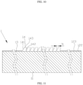
- FIGS. 6 and 7 after completing the winding and flattening of the tabs 211/221, the tabs 211 of the positive electrode tab plate 21 and the tabs 221 of the negative electrode tab plate 22 are respectively overlapped to form a circular structure.
- the orientation of the acute angle on the tabs 211 of the positive electrode tab plate 21 and the orientation of the acute angle on the tabs 221 of the negative electrode tab plate 22 are the same as the winding direction S.
- the rolling pressure required for flattening the tabs 211/221 can be effectively reduced, thereby avoiding the deformation of the positive and negative electrode tab plates 21/22 and reducing the falling off of the active materials from the positive and negative electrode tab plates 21/22, so as to greatly improve the yield rate of full-tab wound cells.
- both the tabs 211 of the positive electrode tab plate 21 and the tabs 221 of the negative electrode tab plate 22 are rounded.
- the intersection of the two sides after being rounded is a smooth transition, which is more conducive to reducing the pressure required to flatten the tabs 211/221 and reducing tip discharge.
- the wound battery also includes a second separator 24.
- the positive electrode tab plate 21, the first separator 23, the negative electrode tab plate 22 and the second separator 24 are sequentially stacked from inside to outside, and are wound to form a battery cell 2 after the four are stacked.
- a distance of the tabs 211 of the positive electrode tab plate 21 beyond a top end of the first separator 23 after being flattened is 0.5-5 mm
- a distance of the tabs 221 of the negative electrode tab plate 22 beyond a bottom end of the first separator 23 after being flattened is less than 5 mm.
- the distance of the tabs 211 of the positive electrode tab plate 21 beyond the top end of the first separator 23 after being flattened is less than 3 mm
- the distance of the tabs 221 of the negative electrode tab plate 22 beyond the bottom end of the first separator 23 after being flattened is less than 3 mm.
- the distance of the tabs 211 of the positive electrode tab plate 21 beyond the top end of the first separator 23 after being flattened is less than 3 mm and greater than 1.5 mm
- the distance of the tabs 221 of the negative electrode tab plate 22 beyond the bottom end of the first separator 23 after being flattened is less than 3 mm and greater than 1.5 mm.
- This embodiment also provides a preparation method for a wound battery, and the method specifically includes: coating the positive electrode tab plate 21 and the negative electrode tab plate 22 using a coating machine to ensure that an empty foil area is formed on both the positive electrode tab plate 21 and the negative electrode tab plate 22; cutting the empty foil area(s) of the positive electrode tab plate 21 and/or the negative electrode tab plate 22 into a plurality of quadrilateral tabs 211/221 through laser cutting; then, winding the positive electrode tab plate 21, the negative electrode tab plate 22 and the separator 23/24 into a cylindrical shape, and bending and flattening the tabs 211/221 towards the central hole 20 during the winding process.
- the tab plate 1 with tabs sets the tabs 14 in a quadrilateral structure, and the angle a formed between the first side 141 and the partition line 123 is an acute angle.
- the winding direction S of the tab plate 1 is consistent with the orientation of the acute angle a.
- the stress of bending the tabs 14 can be reduced, thereby ensuring the quality of the wound battery.
- the cutting area 121 is separated from the coating area 11 through the reserved area 122, which can avoid cutting to the coating area 11 during the formation of the tabs 14 by cutting, so as to prevent the active material powder on the coating area 11 from falling off, thereby avoiding the impact on the electrical performance of the tab plate 1 and facilitating the cutting operation.
- the wound battery not only has a simple design, but also has good electrical performance, high yield rate, and strong practicality.
Landscapes
- Chemical & Material Sciences (AREA)
- Chemical Kinetics & Catalysis (AREA)
- Electrochemistry (AREA)
- General Chemical & Material Sciences (AREA)
- Engineering & Computer Science (AREA)
- Manufacturing & Machinery (AREA)
- Materials Engineering (AREA)
- Connection Of Batteries Or Terminals (AREA)
Applications Claiming Priority (2)
| Application Number | Priority Date | Filing Date | Title |
|---|---|---|---|
| CN202110588973.1A CN113193165B (zh) | 2021-05-28 | 2021-05-28 | 极耳极片及卷绕电池 |
| PCT/CN2022/092890 WO2022247665A1 (zh) | 2021-05-28 | 2022-05-13 | 极耳极片及卷绕电池 |
Publications (1)
| Publication Number | Publication Date |
|---|---|
| EP4350872A1 true EP4350872A1 (en) | 2024-04-10 |
Family
ID=76985729
Family Applications (1)
| Application Number | Title | Priority Date | Filing Date |
|---|---|---|---|
| EP22810392.5A Pending EP4350872A1 (en) | 2021-05-28 | 2022-05-13 | Tab electrode plate and wound battery |
Country Status (3)
| Country | Link |
|---|---|
| EP (1) | EP4350872A1 (zh) |
| CN (1) | CN113193165B (zh) |
| WO (1) | WO2022247665A1 (zh) |
Families Citing this family (12)
| Publication number | Priority date | Publication date | Assignee | Title |
|---|---|---|---|---|
| CN113270693A (zh) * | 2021-05-17 | 2021-08-17 | 微宏动力系统(湖州)有限公司 | 全极耳极片及卷绕电池 |
| CN113193165B (zh) * | 2021-05-28 | 2023-06-06 | 微宏动力系统(湖州)有限公司 | 极耳极片及卷绕电池 |
| EP4307461A1 (en) | 2021-11-19 | 2024-01-17 | LG Energy Solution, Ltd. | Electrode assembly, battery, and battery pack and vehicle including same |
| CN114171774B (zh) * | 2021-11-30 | 2023-02-10 | 湖北亿纬动力有限公司 | 一种电芯加工方法及极耳预弯折装置 |
| CN114335754A (zh) * | 2021-12-24 | 2022-04-12 | 珠海冠宇电池股份有限公司 | 一种电池 |
| CN218456142U (zh) * | 2022-01-28 | 2023-02-07 | 湖北亿纬动力有限公司 | 一种电极组件及储能装置 |
| WO2023206191A1 (zh) * | 2022-04-28 | 2023-11-02 | 宁德时代新能源科技股份有限公司 | 电极组件、电池单体、电池及用电设备 |
| CN114976183B (zh) * | 2022-05-18 | 2023-05-02 | 佛山市天劲新能源科技有限公司 | 一种软包电池滚压控制方法、装置、电子设备及存储介质 |
| CN115036585A (zh) * | 2022-06-08 | 2022-09-09 | 江苏正力新能电池技术有限公司 | 一种电极组件、圆柱电池及其装配方法 |
| WO2024031427A1 (zh) * | 2022-08-10 | 2024-02-15 | 宁德时代新能源科技股份有限公司 | 极片、电极组件、电池单体、电池以及用电装置 |
| WO2024050697A1 (zh) * | 2022-09-06 | 2024-03-14 | 宁德时代新能源科技股份有限公司 | 电极组件、电池单体、电池、用电设备和极耳整形装置 |
| CN116417689B (zh) * | 2023-05-16 | 2023-11-03 | 淮北市千锂鸟新能源科技有限公司 | 多极耳圆柱锂离子电池的制作方法及其锂离子电池 |
Family Cites Families (11)
| Publication number | Priority date | Publication date | Assignee | Title |
|---|---|---|---|---|
| JPH11219694A (ja) * | 1998-02-03 | 1999-08-10 | Shin Kobe Electric Mach Co Ltd | 捲回式円筒形電池 |
| JP2013187077A (ja) * | 2012-03-08 | 2013-09-19 | Panasonic Corp | 捲回型およびスタック型電極電池 |
| JP2014022102A (ja) * | 2012-07-13 | 2014-02-03 | Toyota Industries Corp | 蓄電装置及び二次電池並びに電極の製造方法 |
| CN203481318U (zh) * | 2013-06-06 | 2014-03-12 | 珠海银隆新能源有限公司 | 电池极片及高功率电池 |
| CN206163592U (zh) * | 2016-07-15 | 2017-05-10 | 中天储能科技有限公司 | 一种锂电池电极极耳结构 |
| CN208352427U (zh) * | 2018-05-24 | 2019-01-08 | 银隆新能源股份有限公司 | 一种多极耳的电池极片及锂离子电池 |
| KR20200041625A (ko) * | 2018-10-12 | 2020-04-22 | 삼성에스디아이 주식회사 | 이차전지 |
| CN212783704U (zh) * | 2020-07-23 | 2021-03-23 | 郑州比克新能源汽车有限公司 | 一种圆柱型电池多极耳结构 |
| CN113193165B (zh) * | 2021-05-28 | 2023-06-06 | 微宏动力系统(湖州)有限公司 | 极耳极片及卷绕电池 |
| CN215644609U (zh) * | 2021-07-30 | 2022-01-25 | 蜂巢能源科技有限公司 | 电池极组及电池 |
| CN113921765B (zh) * | 2021-09-29 | 2023-02-21 | 蜂巢能源科技有限公司 | 一种圆柱型锂电池及其制备方法 |
-
2021
- 2021-05-28 CN CN202110588973.1A patent/CN113193165B/zh active Active
-
2022
- 2022-05-13 EP EP22810392.5A patent/EP4350872A1/en active Pending
- 2022-05-13 WO PCT/CN2022/092890 patent/WO2022247665A1/zh active Application Filing
Also Published As
| Publication number | Publication date |
|---|---|
| CN113193165A (zh) | 2021-07-30 |
| WO2022247665A1 (zh) | 2022-12-01 |
| CN113193165B (zh) | 2023-06-06 |
Similar Documents
| Publication | Publication Date | Title |
|---|---|---|
| EP4350872A1 (en) | Tab electrode plate and wound battery | |
| EP4343955A1 (en) | Tab plate and wound battery | |
| WO2022257746A1 (zh) | 一种锂离子电池 | |
| CN107293809A (zh) | 一种软包锂离子电池及其制造方法 | |
| CN105161673B (zh) | 一种多极耳电芯的制造工艺及多极耳电池 | |
| CN108565387A (zh) | 一种锂离子电池电芯极耳激光成型工艺 | |
| CN111668451A (zh) | 一种用于卷绕式多极耳电芯的极片的制备方法、极片及电芯 | |
| CN202695607U (zh) | 一种锂离子电池极片 | |
| CN112531142A (zh) | 一种软包纽扣电池用极片、纽扣电池及其制备方法 | |
| CN218299826U (zh) | 一种极片、卷芯及电池 | |
| CN106898823A (zh) | 一种储液式软包装锂离子电芯以及电池的制备方法 | |
| US20220102817A1 (en) | Multi-tab cylindrical battery roll core and lithium ion battery | |
| CN102769146A (zh) | 一种锂离子电池极芯及其制备方法 | |
| AU2012370347B2 (en) | Lithium-ion battery | |
| CN102024990A (zh) | 功率型锂离子电池电芯制作方法 | |
| CN2713657Y (zh) | 锂离子动力电池 | |
| CN203774408U (zh) | 一种动力储能聚合物锂离子电池 | |
| CN216354375U (zh) | 软包电芯、软包电池、电池模组与动力装置 | |
| CN212365995U (zh) | 一种用于卷绕式多极耳电芯的极片及卷绕式多极耳电芯 | |
| CN114141982A (zh) | 一种极片及电池 | |
| TWI616021B (zh) | 電池芯極片結構 | |
| CN203859195U (zh) | 一种极耳侧面收尾的弧形软包锂离子电池 | |
| CN103346353B (zh) | 一种电池电芯、其制造方法及其电池 | |
| CN219832696U (zh) | 一种全极耳电池极片结构、电池卷芯及圆柱电池 | |
| CN206497942U (zh) | 电池芯极片结构 |
Legal Events
| Date | Code | Title | Description |
|---|---|---|---|
| STAA | Information on the status of an ep patent application or granted ep patent |
Free format text: STATUS: THE INTERNATIONAL PUBLICATION HAS BEEN MADE |
|
| PUAI | Public reference made under article 153(3) epc to a published international application that has entered the european phase |
Free format text: ORIGINAL CODE: 0009012 |
|
| STAA | Information on the status of an ep patent application or granted ep patent |
Free format text: STATUS: REQUEST FOR EXAMINATION WAS MADE |
|
| 17P | Request for examination filed |
Effective date: 20231124 |
|
| AK | Designated contracting states |
Kind code of ref document: A1 Designated state(s): AL AT BE BG CH CY CZ DE DK EE ES FI FR GB GR HR HU IE IS IT LI LT LU LV MC MK MT NL NO PL PT RO RS SE SI SK SM TR |