EP4350320B1 - Verfahren zum testen von fahrzeugkollisionen - Google Patents
Verfahren zum testen von fahrzeugkollisionen Download PDFInfo
- Publication number
- EP4350320B1 EP4350320B1 EP23191941.6A EP23191941A EP4350320B1 EP 4350320 B1 EP4350320 B1 EP 4350320B1 EP 23191941 A EP23191941 A EP 23191941A EP 4350320 B1 EP4350320 B1 EP 4350320B1
- Authority
- EP
- European Patent Office
- Prior art keywords
- time
- vehicle
- collision
- ttc
- target vehicle
- Prior art date
- Legal status (The legal status is an assumption and is not a legal conclusion. Google has not performed a legal analysis and makes no representation as to the accuracy of the status listed.)
- Active
Links
Images


Classifications
-
- G—PHYSICS
- G01—MEASURING; TESTING
- G01M—TESTING STATIC OR DYNAMIC BALANCE OF MACHINES OR STRUCTURES; TESTING OF STRUCTURES OR APPARATUS, NOT OTHERWISE PROVIDED FOR
- G01M17/00—Testing of vehicles
- G01M17/007—Wheeled or endless-tracked vehicles
-
- G—PHYSICS
- G07—CHECKING-DEVICES
- G07C—TIME OR ATTENDANCE REGISTERS; REGISTERING OR INDICATING THE WORKING OF MACHINES; GENERATING RANDOM NUMBERS; VOTING OR LOTTERY APPARATUS; ARRANGEMENTS, SYSTEMS OR APPARATUS FOR CHECKING NOT PROVIDED FOR ELSEWHERE
- G07C5/00—Registering or indicating the working of vehicles
- G07C5/02—Registering or indicating driving, working, idle, or waiting time only
- G07C5/04—Registering or indicating driving, working, idle, or waiting time only using counting means or digital clocks
-
- G—PHYSICS
- G07—CHECKING-DEVICES
- G07C—TIME OR ATTENDANCE REGISTERS; REGISTERING OR INDICATING THE WORKING OF MACHINES; GENERATING RANDOM NUMBERS; VOTING OR LOTTERY APPARATUS; ARRANGEMENTS, SYSTEMS OR APPARATUS FOR CHECKING NOT PROVIDED FOR ELSEWHERE
- G07C5/00—Registering or indicating the working of vehicles
- G07C5/08—Registering or indicating performance data other than driving, working, idle, or waiting time, with or without registering driving, working, idle or waiting time
- G07C5/0841—Registering performance data
- G07C5/085—Registering performance data using electronic data carriers
-
- G—PHYSICS
- G08—SIGNALLING
- G08G—TRAFFIC CONTROL SYSTEMS
- G08G1/00—Traffic control systems for road vehicles
- G08G1/16—Anti-collision systems
- G08G1/166—Anti-collision systems for active traffic, e.g. moving vehicles, pedestrians, bikes
Definitions
- the present invention relates to a vehicle collision test method, and more specifically, to a collision test of a vehicle following a preceding vehicle, i.e., a vehicle collision test method for generating a collision test method and developing a more accurate and safe vehicle test method through the generated collision test method.
- DAS driver assistance systems
- a vision technique provided in a vehicle to acquire images around the vehicle and control driving of the vehicle based on the acquired images.
- Such a collision test may test performance of a vehicle even when the vehicle is stopped by the driver's intention, as well as performance of autonomous driving. Accordingly, it is necessary to select and develop test situations (scenarios) considering various factors related to collision of a vehicle, and review accuracy and effectiveness of the developed test techniques.
- Vehicle control methods for increasing safety of autonomous driven vehicles or vehicles using driver assistance systems are known from e.g. the following documents:
- the present invention has been made in view of the above problems, and it is an object of the present invention to provide a collision test method of a vehicle following a preceding vehicle.
- Another object of the present invention is to increase accuracy of a vehicle collision test method, in which all possible scenarios of the vehicle collision test method are selected, and the selected scenarios are applied.
- another object of the present invention is to select scenarios possible in the vehicle collision test method and measure safety of vehicles in the case of a collision by applying the selected scenarios.
- the present invention provides a vehicle collision test method with the features according to claim 1. Further preferred embodiments are described in the dependent claims.
- the step of selecting as a selection scenario when the calculated time-to-collision is shorter than the second threshold time for the plurality of scenarios may include the steps of: calculating a time-to-collision of the subject vehicle at preset time intervals; and selecting a minimum time-to-collision among the calculated time-to-collisions as a selection scenario.
- the step of selecting a minimum time-to-collision among the calculated time-to-collisions as a selection scenario may include the steps of: storing as a selection scenario when the minimum time-to-collision is shorter than the second threshold time; and storing as a non-selection scenario when the minimum time-to-collision exceeds the second threshold time.
- the first threshold time may be calculated in a driving situation in which the speed of the target vehicle equally follows the speed of the target vehicle.
- the first threshold time may be corrected in a driving situation in which the speed of the target vehicle is different from the speed of the target vehicle.
- the step of storing as a selection scenario when the minimum time-to-collision is shorter than the second threshold time may further include the step of storing driving information of the subject vehicle when the minimum time-to-collision is shorter than the second threshold time and the target vehicle stops or displacements of the target vehicle and the target vehicle are equal.
- the step of storing driving information of the subject vehicle may include the step of storing a plurality of variables including the acceleration of the subject vehicle and the time-to-collision calculated at preset time intervals in a matrix form.
- the step of selecting a minimum time-to-collision among the calculated time-to-collisions as a selection scenario may further include the steps of: storing driving information of the subject vehicle stored as the selection scenario or the non-selection scenario in a matrix form; and analyzing a driving habit of the subject vehicle based on the stored driving information of the subject vehicle.
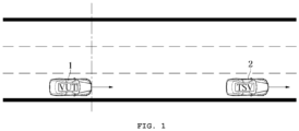
- FIG. 1 is a schematic diagram showing a target vehicle and a subject vehicle following the target vehicle according to an embodiment of the present invention.
- FIG. 1 shows a target vehicle (Traffic Simulation Vehicle; TSV) 2 and a subject vehicle (Vehicle Under Test; VUT) 1 following the target vehicle.
- TSV Traffic Simulation Vehicle
- VUT Vehicle Under Test
- a subject vehicle following a target vehicle drives with a predetermined distance to prevent collision. This is the same when a vehicle is driven by the driver's will, as well as when the vehicle is driven by autonomous driving.
- the distance between the vehicles is set in consideration of a time-to-collision (TTC), which is a period required until the subject vehicle 1 collides with the target vehicle 2 when the target vehicle 2 reduces speed while the subject vehicle 1 and the target vehicle 2 drive at the same speed and the approaching speed of the subject vehicle 1 is constant.
- TTC time-to-collision
- FIG. 2 is a graph showing risk levels of a scenario considering the factors of time-to-collision (TTC) and vehicle speed V in a vehicle collision test method according to an embodiment of the present invention.
- TTC time-to-collision
- the X-axis in FIG. 2 means the time-to-collision [sec], and the Y-axis means the vehicle speed (m/s).
- the vehicle speed means the speed of the target vehicle 2 set in the vehicle collision test method. In the vehicle collision test method, since the subject vehicle 1 to be tested follows the set speed of the target vehicle 2, it is assumed that the speeds of the target vehicle 2 and the subject vehicle 1 are the same, i.e., vehicle speed V.
- various factors such as deceleration (m/s2), road slope (%), initial relative distance between the subject vehicle 1 and the target vehicle 2, and the like, in addition to the TTC and the vehicle speed, may be added to the factors considered in the vehicle collision test method.
- a 'not avoidable scenario 10' is marked as a black area.
- a 'failure scenario 20' is a scenario that is safer than the 'not avoidable scenario', but is not considered as safe, and is marked as a gray area.
- a 'critical scenario 30' is a scenario that can be regarded as relatively safe, and is marked in light gray.
- the white area shows a 'Nominal Scenario' 40, which is a general driving situation that cannot be regarded as a collision situation.
- 11 sections of the vehicle speed V may be set at the intervals of 10km/hr in a range of 10 to 110km/hr.
- 9 sections of the deceleration of the subject vehicle may be set at the intervals of 1m/s 2 in a range of 0 to 8.33m/s 2 . Accordingly, 11*9 scenarios, i.e., 99 scenarios, combining the vehicle speed and the deceleration factor of the subject vehicle may be generated.
- sampling of 99 scenarios may be performed in the vehicle collision test method.
- a threshold TTC may be set, and a scenario having a TTC lower than the threshold TTC may be finally selected as a selection scenario.
- threshold TTC when the threshold TTC is selected as 1.5[sec] in the 99 scenarios described above, finally sampled selection scenarios may be reduced to 22 scenarios.
- the method of determining the threshold TTC will be described below with reference to FIGS. 6 to 8 .
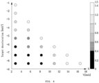
- FIG. 3 is a graph showing the speed, deceleration, and minimum TTC of vehicles (TSV and VUT) in each scenario generated by the vehicle collision test method according to an embodiment of the present invention.
- the X-axis in FIG. 3 means the speeds (m/s) of the target vehicle 2 and the subject vehicle 1
- the Y-axis means the target deceleration (m/s2)
- the Z-axis means the minimum TTC.
- FIG. 3 shows 99 scenarios, which are generated by combining the vehicle speed in each of the 11 sections generated at the intervals of 10km/hr in a range of 10 to 110km/hr and the deceleration of the subject vehicle in each of the 9 sections generated at the intervals of 1m/s 2 in a range of 0 to 8.33m/s 2 , and a minimum TTC corresponding to each scenario.
- sampling may be performed for the 99 scenarios.
- a threshold TTC may be set, and some of the scenarios having a TTC lower than the threshold TTC may be finally selected as selection scenarios.
- FIG. 4 is a graph showing risk levels of each scenario in the case of a TTC lower than a threshold TTC in a collision test method according to an embodiment of the present invention.
- FIG. 4 shows a graph of selection scenarios having a TTC lower than the threshold TTC when the threshold TTC is set to 1.5[sec].
- the X-axis means vehicle speed
- the Y-axis means deceleration.
- the risk level is displayed to be different in each scenario.
- FIG. 5 is a graph showing the speed, deceleration, and minimum TTC of vehicles (TSV and VUT) in each scenario generated according to a collision test method according to an embodiment of the present invention, in which the shaded scenarios correspond to minimum deceleration.
- driver model will be described in FIG. 6 .
- driving on a highway may be considered as an example, like the subject vehicle 1 shown in FIG. 1 following the target vehicle 2.
- the driver model is for selecting a scenario for observing the ability of an automatic deceleration function in a sudden deceleration of the target vehicle 2 while the subject vehicle 1 is driving maintaining a predetermined safe distance with the target vehicle 2.
- the brake pedal begins to be engaged from time point p5 after passing through time point p3 of determining a danger, the section of releasing the accelerator pedal p3-p4, and the section of moving the driver's foot from the accelerator pedal to the brake pedal p4-p5.
- TTC time-to-collision
- the TTC denotes the time-to-collision
- d rel denotes the distance between the target vehicle (TSV) 2 and the subject vehicle (VUT) 1
- v rel denotes the relative speed between the target vehicle (TSV) 2 and the subject vehicle (VUT) 1
- V tsv denotes the speed of the target vehicle (TSV) 2
- V vut denotes the speed of the subject vehicle (VUT) 1.
- the TTC may be calculated at time intervals of 0.01[sec]. At this point, when the calculated TTC belongs to a risk scenario, corresponding information will be stored.
- the vehicle collision test method may operate on a system or a program stored in a computer readable recording medium.
- a control unit (not shown) in a system, in which the vehicle collision test method operates, comprehensively controls the vehicle collision test method.
- the system in which the vehicle collision test method operates includes a storage unit and stores data values in a matrix form.
- the storage unit may be implemented as at least one among a non-volatile memory device such as a cache, a read-only memory (ROM), a programmable ROM (PROM), an erasable programmable ROM (EPROM), an electrically erasable programmable ROM (EEPROM), or a flash memory, a volatile memory device such as a random-access memory (RAM), and a storage medium such as a hard disk drive (HDD) or a CD-ROM, it is not limited thereto.
- a non-volatile memory device such as a cache
- ROM read-only memory
- PROM programmable ROM
- EPROM erasable programmable ROM
- EEPROM electrically erasable programmable ROM
- flash memory a volatile memory device such as a random-access memory (RAM)
- RAM random-access memory
- HDD hard disk drive
- CD-ROM compact disc-read only memory
- the storage unit may be a memory implemented as a chip separate from the control unit described above, or may be implemented as a processor and a single chip.
- FIG. 7 is a flowchart illustrating a collision test method according to an embodiment of the present invention.
- variables are set to calculate a scenario (700).
- various variables such as deceleration (m/s2), road slope (%), initial relative distance between the subject vehicle 1 and the target vehicle 2, and the like, in addition to the TTC and the vehicle speed, may correspond to the factors considered in the vehicle collision test method.
- combinations of variables are calculated (710). For example, when the vehicle speed V is set to 11 sections and the target deceleration is set to 9 sections, scenarios combining the vehicle speed and the target deceleration, i.e., 99 scenarios, may be generated.
- results of applying the calculated scenarios are stored.
- result values according to the 99 scenarios are stored (720).
- derivation of scenarios has been described in FIG. 7
- step 720 of storing result values according to the derived scenarios will be described in detail in FIG. 8 .
- FIG. 8 is a flowchart illustrating a scenario of a collision test method according to an embodiment of the present invention.
- FIG. 8 is a flowchart illustrating a process of applying the 99 scenarios generated using deceleration and vehicle speed in a collision test method according to an embodiment.
- the target vehicle 2 is controlled to test the operation of the subject vehicle 1.
- the target vehicle decelerates YES at 810
- a first threshold time th1 set in advance is exceeded from the time point of beginning the deceleration of the target vehicle, the subject vehicle begins to decelerate (830).
- the threshold time th1 is a time determined in consideration of actual beginning of deceleration, although the target vehicle 2 begins to decelerate, after the driver or the autonomous driving system actually spends a risk determination time of recognizing deceleration of the target vehicle 2 as a risk and a risk response time.
- the threshold time th1 is set in consideration of the time when risk is recognized and determined as a risk and the mechanical time until the brake pedal actually operates.
- the threshold time th1 in FIG. 8 may be determined in consideration of the risk determination time and the mechanical time until the brake pedal operates, assuming that the target vehicle 2 begins to decelerate while the target vehicle 2 and the subject vehicle 1 are traveling at the same speed.
- the threshold time th1 may be set by correcting the threshold time th1 when the speed of the target vehicle 2 is not the same.
- a first threshold time may be set by adding a correction value to the threshold time th1.
- the correction value may be set to be subdivided according to the degree of acceleration of the target vehicle 2 and the degree of acceleration of the subject vehicle 1.
- the correction value may be subdivided by comparing the degree of acceleration of the target vehicle 2 and the subject vehicle 1, i.e., magnitude of acceleration.
- the first threshold time may be set by assigning a (-) correction value to the threshold time th1.
- a TTC is calculated (840).
- the TTC may be calculated at time intervals of 0.01[sec].
- the TTC calculated at each preset time point is compared with a preset second threshold time th2 (850).
- the second threshold time th2 is set to be longer than the first threshold time th1.
- a case in which the subject vehicle is stopped i.e., the speed of the subject vehicle is 0
- a case in which the displacement (location) of the subject vehicle 1 is the same as the displacement of the target vehicle 2, as well as the case in which the subject vehicle is stopped may also be selected as a selection scenario.
- the vehicle collision test method may be adopted in the subject vehicle 1 to analyze the stored selection scenarios and non-selection scenarios and analyze the driving habits of the subject vehicle 1 using big data considering the storage frequency of each scenario.
- the TTC indicates not a dangerous situation, and the corresponding scenario is a non-selection scenario, and parameters of the corresponding variables may be stored in a matrix form.
- selection scenarios or non-selection scenarios are stored in a matrix form, all variables of individual scenarios are stored, and individual scenarios may be compared using minimum TTC values, and a priority may be derived for each scenario.
- accuracy of the vehicle collision test method can be increased by selecting all possible scenarios of the vehicle collision test method and applying the selected scenarios.
- safety of each vehicle in the case of a collision can be measured by selecting all scenarios possible in the vehicle collision test method and applying the selected scenarios.
Landscapes
- Physics & Mathematics (AREA)
- General Physics & Mathematics (AREA)
- Traffic Control Systems (AREA)
- Engineering & Computer Science (AREA)
- Automation & Control Theory (AREA)
- Transportation (AREA)
- Mechanical Engineering (AREA)
Claims (8)
- Ein Fahrzeugkollision-Testverfahren, die Schritte aufweisend:Einstellen (700) einer Geschwindigkeit und einer Zielbeschleunigung eines Zielfahrzeugs (2);Beobachten einer Geschwindigkeit und einer Beschleunigung eines Testfahrzeugs (1), die zu der eingestellten Geschwindigkeit und der Zielbeschleunigung des Zielfahrzeugs (2) korrespondieren;Verzögern des Testfahrzeugs (1) und Berechnen (840) einer Zeit bis zur Kollision (TTC), wenn eine erste Schwellenwertzeit (TH1) nach der Verzögerung des Zielfahrzeugs (2) überschritten wird; undSpeichern (870) von Informationen über das Testfahrzeug (1), wenn die berechnete Zeit bis zur Kollision (TTC) kürzer ist als eine voreingestellte zweite Schwellenwertzeit (TH2), die länger ist als die erste Schwellenwertzeit (TH1), wobeider Schritt (870) des Speicherns von Informationen über das Testfahrzeug (1), wenn die berechnete Zeit bis zur Kollision (TTC) kürzer ist als die zweite Schwellenwertzeit (TH2), die Schritte aufweist:Einstellen der Geschwindigkeit des Zielfahrzeugs (2), um in Abschnittsintervalle unterteilt zu sein;Einstellen der Beschleunigung des Zielfahrzeugs (2), um in Abschnittsintervalle unterteilt zu sein;Auswählen einer Mehrzahl von Szenarien durch Kombinieren der eingestellten Abschnittsintervalle der Geschwindigkeit des Zielfahrzeugs (2) und der eingestellten Abschnittsintervalle der Beschleunigung des Zielfahrzeugs (2); undAuswählen als ein Auswahlszenario für die Mehrzahl von Szenarien, wenn die berechnete Zeit bis zur Kollision (TTC) kürzer ist als die zweite Schwellenwertzeit (TH2),wobei die erste Schwellenwertzeit (TH1) unter Berücksichtigung einer Risikoermittlungszeit und einer mechanischen Pedalübertragungszeit des Testfahrzeugs (1) eingestellt wird und eine Zeit ist, die das Testfahrzeug (1) benötigt, um als Reaktion auf die erkannte Verzögerung des Zielfahrzeugs (2) mit der Verzögerung zu beginnen,wobei die Berechnung der Zeit bis zur Kollision (TTC) unter Verwendung der Gleichung durchgeführt wird:
 TTC die Zeit bis zur Kollision bezeichnet,drel die Distanz zwischen dem Zielfahrzeug (2) und dem Testfahrzeug (1) bezeichnet,vrel die relative Geschwindigkeit zwischen dem Zielfahrzeug (2) und dem Testfahrzeug (1) bezeichnet,Vtsv die Geschwindigkeit des Zielfahrzeugs (2) bezeichnet undVvut die Geschwindigkeit des Testfahrzeugs (1) bezeichnet.
 - Das Verfahren gemäß Anspruch 1, wobei der Schritt des Auswählens für die Mehrzahl von Szenarien als ein Auswahlszenario, wenn die berechnete Zeit bis zur Kollision (TTC) kürzer als die zweite Schwellenwertzeit (TH2) ist, die Schritte aufweist:Berechnen einer Zeit bis zur Kollision (TTC) des Zielfahrzeugs (1) in voreingestellten Zeitintervallen; undAuswählen einer minimalen Zeit bis zur Kollision (TTC) unter den berechneten Zeiten bis zur Kollision (TTC) als ein Auswahlszenario.
- Das Verfahren gemäß Anspruch 2, wobei der Schritt des Auswählens einer minimalen Zeit bis zur Kollision unter den berechneten Zeiten bis zur Kollision (TTC) als ein Auswahlszenario die Schritte aufweist:Speichern (870) als ein Auswahlszenario, wenn die minimale Zeit bis zur Kollision kürzer ist als die zweite Schwellenwertzeit (TH2); undSpeichern als ein Nicht-Auswahl-Szenario, wenn die minimale Zeit bis zur Kollision die zweite Schwellenwertzeit (TH2) überschreitet.
- Das Verfahren gemäß Anspruch 1, wobei die erste Schwellenwertzeit (TH1) in einer Fahrsituation berechnet wird, in der die Geschwindigkeit des Zielfahrzeugs (2) gleichmäßig der Geschwindigkeit des Zielfahrzeugs (2) folgt.
- Das Verfahren gemäß Anspruch 4, wobei die erste Schwellenwertzeit (TH1) in einer Fahrsituation korrigiert wird, in der die Geschwindigkeit des Zielfahrzeugs (2) von der Geschwindigkeit des Zielfahrzeugs (2) abweicht.
- Das Verfahren gemäß Anspruch 3, wobei der Schritt (870) des Speicherns als ein Auswahlszenario, wenn die minimale Zeit bis zur Kollision kürzer als die zweite Schwellenwertzeit (TH2) ist, ferner den Schritt des Speicherns von Fahrinformationen des Testfahrzeugs (1) aufweist, wenn die minimale Zeit bis zur Kollision kürzer als die zweite Schwellenwertzeit (TH2) ist und das Zielfahrzeug (2) anhält oder Entfernungen des Zielfahrzeugs (2) und des Zielfahrzeugs ( 2) gleich sind.
- Das Verfahren gemäß Anspruch 6, wobei der Schritt (870) des Speicherns von Fahrinformationen des Testfahrzeugs (1) den Schritt des Speicherns einer Mehrzahl von Variablen, einschließlich der Beschleunigung des Testfahrzeugs (1) und der in voreingestellten Zeitintervallen berechneten Zeit bis zur Kollision (TTC), in Matrixform aufweist.
- Das Verfahren gemäß Anspruch 3, wobei der Schritt des Auswählens einer minimalen Zeit bis zur Kollision unter den berechneten Zeiten bis zur Kollision (TTC) als ein Auswahlszenario ferner die Schritte aufweist:Speichern von Fahrinformationen des Testfahrzeugs (1), die als das Auswahlszenario oder das Nicht-Auswahl-Szenario in einer Matrixform gespeichert sind; undAnalysieren einer Fahrgewohnheit des Testfahrzeugs (1) auf der Grundlage der gespeicherten Fahrinformationen des Testfahrzeugs (1).
Applications Claiming Priority (1)
| Application Number | Priority Date | Filing Date | Title |
|---|---|---|---|
| KR1020220102537A KR102562790B1 (ko) | 2022-08-17 | 2022-08-17 | 차량 충돌 시험 방법 |
Publications (3)
| Publication Number | Publication Date |
|---|---|
| EP4350320A1 EP4350320A1 (de) | 2024-04-10 |
| EP4350320B1 true EP4350320B1 (de) | 2025-05-21 |
| EP4350320C0 EP4350320C0 (de) | 2025-05-21 |
Family
ID=87561171
Family Applications (1)
| Application Number | Title | Priority Date | Filing Date |
|---|---|---|---|
| EP23191941.6A Active EP4350320B1 (de) | 2022-08-17 | 2023-08-17 | Verfahren zum testen von fahrzeugkollisionen |
Country Status (4)
| Country | Link |
|---|---|
| US (1) | US12002303B2 (de) |
| EP (1) | EP4350320B1 (de) |
| JP (1) | JP7476412B2 (de) |
| KR (1) | KR102562790B1 (de) |
Families Citing this family (2)
| Publication number | Priority date | Publication date | Assignee | Title |
|---|---|---|---|---|
| CN118150188A (zh) * | 2024-03-11 | 2024-06-07 | 北京智能车联产业创新中心有限公司 | 自动驾驶车辆路口冲突测试方法及装置 |
| CN120742855B (zh) * | 2025-08-19 | 2025-11-25 | 北京智能车联产业创新中心有限公司 | 封闭场地自动驾驶多目标车冲突序列的低成本动态触发测试方法及系统 |
Family Cites Families (6)
| Publication number | Priority date | Publication date | Assignee | Title |
|---|---|---|---|---|
| JP3758970B2 (ja) * | 2000-11-24 | 2006-03-22 | アイシン精機株式会社 | 車両の衝突予防装置 |
| JP2011121491A (ja) * | 2009-12-11 | 2011-06-23 | Toyota Motor Corp | 運転支援装置 |
| DE102010051203B4 (de) * | 2010-11-12 | 2022-07-28 | Zf Active Safety Gmbh | Verfahren zur Erkennung von kritischen Fahrsituationen von Lastkraft- oder Personenkraftwagen, insbesondere zur Vermeidung von Kollisionen |
| JP2018180880A (ja) * | 2017-04-12 | 2018-11-15 | トヨタ自動車株式会社 | 衝突データ記憶装置及び衝突データ記憶方法 |
| JP6614688B1 (ja) * | 2019-03-04 | 2019-12-04 | 独立行政法人自動車技術総合機構 | 制動評価装置、制動評価方法、自動制動パターンの評価閾値の生成方法、自動制動パターンの基礎データの収集方法 |
| DE112021005100T5 (de) * | 2020-12-18 | 2023-10-12 | Hitachi Astemo, Ltd. | Informationserzeugungsvorrichtung |
-
2022
- 2022-08-17 KR KR1020220102537A patent/KR102562790B1/ko active Active
-
2023
- 2023-08-17 JP JP2023132755A patent/JP7476412B2/ja active Active
- 2023-08-17 EP EP23191941.6A patent/EP4350320B1/de active Active
- 2023-08-17 US US18/451,603 patent/US12002303B2/en active Active
Also Published As
| Publication number | Publication date |
|---|---|
| US20240062591A1 (en) | 2024-02-22 |
| JP7476412B2 (ja) | 2024-04-30 |
| EP4350320C0 (de) | 2025-05-21 |
| KR102562790B1 (ko) | 2023-08-07 |
| JP2024028208A (ja) | 2024-03-01 |
| US12002303B2 (en) | 2024-06-04 |
| EP4350320A1 (de) | 2024-04-10 |
Similar Documents
| Publication | Publication Date | Title |
|---|---|---|
| EP4350320B1 (de) | Verfahren zum testen von fahrzeugkollisionen | |
| EP1332910B1 (de) | Verfahren und System zur Verbesserung der Fahrerunterstützung | |
| Sugimoto et al. | Effectiveness estimation method for advanced driver assistance system and its application to collision mitigation brake system | |
| US9937930B2 (en) | Virtual test optimization for driver assistance systems | |
| EP3887219B1 (de) | Verbessertes autobahnunterstützungsszenario | |
| EP3960566B1 (de) | System zur vorhersage des kollisionsrisikos bei einer spurwechselentscheidung basierend auf einem radarsensor und entsprechendes verfahren | |
| KR102095884B1 (ko) | 차량의 거동 정보 기반 도로위험지표 산출 방법 및 그 장치 | |
| KR102002421B1 (ko) | 차량 주행 환경을 고려한 크루즈 컨트롤 장치 및 방법 | |
| EP4092633A1 (de) | Verfahren und vorrichtung zur spurwechselvorhersage eines zielfahrzeugs | |
| US12570297B2 (en) | System, method and software for operating a driver assistance system | |
| US11292463B2 (en) | Determination of a control signal for an in-part-autonomous vehicle | |
| CN105480225A (zh) | 车辆碰撞后前向运动的减缓 | |
| CN113849971B (zh) | 驾驶系统评估方法、装置、计算机设备和存储介质 | |
| Li et al. | Evaluation of Forward Collision Avoidance system using driver's hazard perception | |
| Brown et al. | Attention-based model of driver performance in rear-end collisions | |
| KR20190067098A (ko) | 전기 차량 또는 하이브리드 차량을 구동하기 위한 방법 및 제어 장치 | |
| CN109421687A (zh) | 制动系统延时自学习方法以及计算机可读存储介质 | |
| EP4144601A1 (de) | Bestimmung der geschätzten beschleunigung für eine automatische notbremsung | |
| CN114179621A (zh) | 车辆的陡坡缓降控制方法及装置 | |
| CN116001788A (zh) | 跟车方法、电子设备、车辆及存储介质 | |
| KR100906667B1 (ko) | 종방향 차속 자동제어시스템 | |
| CN113895440B (zh) | 一种高速公路自动变道方法、装置、电子设备及存储介质 | |
| CN118107570A (zh) | 规避危险驾驶车辆的路径规划方法、装置、车辆及介质 | |
| Fuerbeth | Post-collision run-out vehicle deceleration based on real-world data | |
| Perron et al. | Active safety experiments with common drivers for the specification of active safety systems |
Legal Events
| Date | Code | Title | Description |
|---|---|---|---|
| PUAI | Public reference made under article 153(3) epc to a published international application that has entered the european phase |
Free format text: ORIGINAL CODE: 0009012 |
|
| STAA | Information on the status of an ep patent application or granted ep patent |
Free format text: STATUS: THE APPLICATION HAS BEEN PUBLISHED |
|
| STAA | Information on the status of an ep patent application or granted ep patent |
Free format text: STATUS: REQUEST FOR EXAMINATION WAS MADE |
|
| AK | Designated contracting states |
Kind code of ref document: A1 Designated state(s): AL AT BE BG CH CY CZ DE DK EE ES FI FR GB GR HR HU IE IS IT LI LT LU LV MC ME MK MT NL NO PL PT RO RS SE SI SK SM TR |
|
| 17P | Request for examination filed |
Effective date: 20240328 |
|
| RBV | Designated contracting states (corrected) |
Designated state(s): AL AT BE BG CH CY CZ DE DK EE ES FI FR GB GR HR HU IE IS IT LI LT LU LV MC ME MK MT NL NO PL PT RO RS SE SI SK SM TR |
|
| GRAP | Despatch of communication of intention to grant a patent |
Free format text: ORIGINAL CODE: EPIDOSNIGR1 |
|
| STAA | Information on the status of an ep patent application or granted ep patent |
Free format text: STATUS: GRANT OF PATENT IS INTENDED |
|
| RIC1 | Information provided on ipc code assigned before grant |
Ipc: G08G 1/16 20060101ALI20241206BHEP Ipc: G01M 17/007 20060101AFI20241206BHEP |
|
| INTG | Intention to grant announced |
Effective date: 20241219 |
|
| GRAS | Grant fee paid |
Free format text: ORIGINAL CODE: EPIDOSNIGR3 |
|
| GRAA | (expected) grant |
Free format text: ORIGINAL CODE: 0009210 |
|
| STAA | Information on the status of an ep patent application or granted ep patent |
Free format text: STATUS: THE PATENT HAS BEEN GRANTED |
|
| AK | Designated contracting states |
Kind code of ref document: B1 Designated state(s): AL AT BE BG CH CY CZ DE DK EE ES FI FR GB GR HR HU IE IS IT LI LT LU LV MC ME MK MT NL NO PL PT RO RS SE SI SK SM TR |
|
| REG | Reference to a national code |
Ref country code: GB Ref legal event code: FG4D |
|
| REG | Reference to a national code |
Ref country code: CH Ref legal event code: EP |
|
| REG | Reference to a national code |
Ref country code: DE Ref legal event code: R096 Ref document number: 602023003588 Country of ref document: DE |
|
| REG | Reference to a national code |
Ref country code: IE Ref legal event code: FG4D |
|
| U01 | Request for unitary effect filed |
Effective date: 20250603 |
|
| U07 | Unitary effect registered |
Designated state(s): AT BE BG DE DK EE FI FR IT LT LU LV MT NL PT RO SE SI Effective date: 20250611 |
|
| U20 | Renewal fee for the european patent with unitary effect paid |
Year of fee payment: 3 Effective date: 20250829 |
|
| PG25 | Lapsed in a contracting state [announced via postgrant information from national office to epo] |
Ref country code: ES Free format text: LAPSE BECAUSE OF FAILURE TO SUBMIT A TRANSLATION OF THE DESCRIPTION OR TO PAY THE FEE WITHIN THE PRESCRIBED TIME-LIMIT Effective date: 20250521 |
|
| PG25 | Lapsed in a contracting state [announced via postgrant information from national office to epo] |
Ref country code: NO Free format text: LAPSE BECAUSE OF FAILURE TO SUBMIT A TRANSLATION OF THE DESCRIPTION OR TO PAY THE FEE WITHIN THE PRESCRIBED TIME-LIMIT Effective date: 20250821 Ref country code: GR Free format text: LAPSE BECAUSE OF FAILURE TO SUBMIT A TRANSLATION OF THE DESCRIPTION OR TO PAY THE FEE WITHIN THE PRESCRIBED TIME-LIMIT Effective date: 20250822 |
|
| PG25 | Lapsed in a contracting state [announced via postgrant information from national office to epo] |
Ref country code: PL Free format text: LAPSE BECAUSE OF FAILURE TO SUBMIT A TRANSLATION OF THE DESCRIPTION OR TO PAY THE FEE WITHIN THE PRESCRIBED TIME-LIMIT Effective date: 20250521 |
|
| PG25 | Lapsed in a contracting state [announced via postgrant information from national office to epo] |
Ref country code: HR Free format text: LAPSE BECAUSE OF FAILURE TO SUBMIT A TRANSLATION OF THE DESCRIPTION OR TO PAY THE FEE WITHIN THE PRESCRIBED TIME-LIMIT Effective date: 20250521 |
|
| PG25 | Lapsed in a contracting state [announced via postgrant information from national office to epo] |
Ref country code: RS Free format text: LAPSE BECAUSE OF FAILURE TO SUBMIT A TRANSLATION OF THE DESCRIPTION OR TO PAY THE FEE WITHIN THE PRESCRIBED TIME-LIMIT Effective date: 20250821 |
|
| PG25 | Lapsed in a contracting state [announced via postgrant information from national office to epo] |
Ref country code: IS Free format text: LAPSE BECAUSE OF FAILURE TO SUBMIT A TRANSLATION OF THE DESCRIPTION OR TO PAY THE FEE WITHIN THE PRESCRIBED TIME-LIMIT Effective date: 20250921 |
|
| PG25 | Lapsed in a contracting state [announced via postgrant information from national office to epo] |
Ref country code: SM Free format text: LAPSE BECAUSE OF FAILURE TO SUBMIT A TRANSLATION OF THE DESCRIPTION OR TO PAY THE FEE WITHIN THE PRESCRIBED TIME-LIMIT Effective date: 20250521 |
|
| PG25 | Lapsed in a contracting state [announced via postgrant information from national office to epo] |
Ref country code: CZ Free format text: LAPSE BECAUSE OF FAILURE TO SUBMIT A TRANSLATION OF THE DESCRIPTION OR TO PAY THE FEE WITHIN THE PRESCRIBED TIME-LIMIT Effective date: 20250521 |
|
| PG25 | Lapsed in a contracting state [announced via postgrant information from national office to epo] |
Ref country code: SK Free format text: LAPSE BECAUSE OF FAILURE TO SUBMIT A TRANSLATION OF THE DESCRIPTION OR TO PAY THE FEE WITHIN THE PRESCRIBED TIME-LIMIT Effective date: 20250521 |
|
| PLBE | No opposition filed within time limit |
Free format text: ORIGINAL CODE: 0009261 |
|
| STAA | Information on the status of an ep patent application or granted ep patent |
Free format text: STATUS: NO OPPOSITION FILED WITHIN TIME LIMIT |