EP4350178A1 - Drehgelenkanordnung einer offshore-plattform-energieanlage und anlage mit einer solchen vorrichtung - Google Patents
Drehgelenkanordnung einer offshore-plattform-energieanlage und anlage mit einer solchen vorrichtung Download PDFInfo
- Publication number
- EP4350178A1 EP4350178A1 EP23201718.6A EP23201718A EP4350178A1 EP 4350178 A1 EP4350178 A1 EP 4350178A1 EP 23201718 A EP23201718 A EP 23201718A EP 4350178 A1 EP4350178 A1 EP 4350178A1
- Authority
- EP
- European Patent Office
- Prior art keywords
- heel
- lip
- sealing member
- joint device
- dynamic sealing
- Prior art date
- Legal status (The legal status is an assumption and is not a legal conclusion. Google has not performed a legal analysis and makes no representation as to the accuracy of the status listed.)
- Pending
Links
- 238000009434 installation Methods 0.000 title claims abstract description 31
- 238000007789 sealing Methods 0.000 claims abstract description 95
- 125000006850 spacer group Chemical group 0.000 claims abstract 2
- 239000012530 fluid Substances 0.000 claims description 32
- 239000011324 bead Substances 0.000 claims description 19
- 230000003014 reinforcing effect Effects 0.000 claims description 17
- 229930195733 hydrocarbon Natural products 0.000 claims description 9
- 150000002430 hydrocarbons Chemical class 0.000 claims description 9
- 230000005611 electricity Effects 0.000 claims description 6
- 239000004215 Carbon black (E152) Substances 0.000 claims description 3
- 101100420946 Caenorhabditis elegans sea-2 gene Proteins 0.000 description 3
- 238000004519 manufacturing process Methods 0.000 description 3
- 238000005096 rolling process Methods 0.000 description 3
- 230000015572 biosynthetic process Effects 0.000 description 2
- 238000004140 cleaning Methods 0.000 description 2
- 230000007613 environmental effect Effects 0.000 description 2
- 238000003860 storage Methods 0.000 description 2
- 230000000295 complement effect Effects 0.000 description 1
- 238000005520 cutting process Methods 0.000 description 1
- 230000007423 decrease Effects 0.000 description 1
- SYHGEUNFJIGTRX-UHFFFAOYSA-N methylenedioxypyrovalerone Chemical compound C=1C=C2OCOC2=CC=1C(=O)C(CCC)N1CCCC1 SYHGEUNFJIGTRX-UHFFFAOYSA-N 0.000 description 1
- 230000002787 reinforcement Effects 0.000 description 1
- 230000000284 resting effect Effects 0.000 description 1
- XLYOFNOQVPJJNP-UHFFFAOYSA-N water Substances O XLYOFNOQVPJJNP-UHFFFAOYSA-N 0.000 description 1
Images

Classifications
-
- F—MECHANICAL ENGINEERING; LIGHTING; HEATING; WEAPONS; BLASTING
- F16—ENGINEERING ELEMENTS AND UNITS; GENERAL MEASURES FOR PRODUCING AND MAINTAINING EFFECTIVE FUNCTIONING OF MACHINES OR INSTALLATIONS; THERMAL INSULATION IN GENERAL
- F16L—PIPES; JOINTS OR FITTINGS FOR PIPES; SUPPORTS FOR PIPES, CABLES OR PROTECTIVE TUBING; MEANS FOR THERMAL INSULATION IN GENERAL
- F16L27/00—Adjustable joints, Joints allowing movement
- F16L27/08—Adjustable joints, Joints allowing movement allowing adjustment or movement only about the axis of one pipe
- F16L27/0804—Adjustable joints, Joints allowing movement allowing adjustment or movement only about the axis of one pipe the fluid passing axially from one joint element to another
-
- F—MECHANICAL ENGINEERING; LIGHTING; HEATING; WEAPONS; BLASTING
- F16—ENGINEERING ELEMENTS AND UNITS; GENERAL MEASURES FOR PRODUCING AND MAINTAINING EFFECTIVE FUNCTIONING OF MACHINES OR INSTALLATIONS; THERMAL INSULATION IN GENERAL
- F16J—PISTONS; CYLINDERS; SEALINGS
- F16J15/00—Sealings
- F16J15/16—Sealings between relatively-moving surfaces
- F16J15/32—Sealings between relatively-moving surfaces with elastic sealings, e.g. O-rings
- F16J15/3204—Sealings between relatively-moving surfaces with elastic sealings, e.g. O-rings with at least one lip
- F16J15/3232—Sealings between relatively-moving surfaces with elastic sealings, e.g. O-rings with at least one lip having two or more lips
- F16J15/3236—Sealings between relatively-moving surfaces with elastic sealings, e.g. O-rings with at least one lip having two or more lips with at least one lip for each surface, e.g. U-cup packings
-
- B—PERFORMING OPERATIONS; TRANSPORTING
- B63—SHIPS OR OTHER WATERBORNE VESSELS; RELATED EQUIPMENT
- B63B—SHIPS OR OTHER WATERBORNE VESSELS; EQUIPMENT FOR SHIPPING
- B63B21/00—Tying-up; Shifting, towing, or pushing equipment; Anchoring
- B63B21/50—Anchoring arrangements or methods for special vessels, e.g. for floating drilling platforms or dredgers
- B63B21/507—Anchoring arrangements or methods for special vessels, e.g. for floating drilling platforms or dredgers with mooring turrets
-
- F—MECHANICAL ENGINEERING; LIGHTING; HEATING; WEAPONS; BLASTING
- F16—ENGINEERING ELEMENTS AND UNITS; GENERAL MEASURES FOR PRODUCING AND MAINTAINING EFFECTIVE FUNCTIONING OF MACHINES OR INSTALLATIONS; THERMAL INSULATION IN GENERAL
- F16J—PISTONS; CYLINDERS; SEALINGS
- F16J15/00—Sealings
- F16J15/002—Sealings comprising at least two sealings in succession
-
- F—MECHANICAL ENGINEERING; LIGHTING; HEATING; WEAPONS; BLASTING
- F16—ENGINEERING ELEMENTS AND UNITS; GENERAL MEASURES FOR PRODUCING AND MAINTAINING EFFECTIVE FUNCTIONING OF MACHINES OR INSTALLATIONS; THERMAL INSULATION IN GENERAL
- F16J—PISTONS; CYLINDERS; SEALINGS
- F16J15/00—Sealings
- F16J15/16—Sealings between relatively-moving surfaces
- F16J15/32—Sealings between relatively-moving surfaces with elastic sealings, e.g. O-rings
- F16J15/3204—Sealings between relatively-moving surfaces with elastic sealings, e.g. O-rings with at least one lip
Definitions
- the invention relates to installations for exploiting energy, in particular fluids and for example hydrocarbons or gas, or electricity, on platforms of the offshore type, and in particular the rotary joint devices used in such installations.
- Rotary joint devices installed in pressure installations can, among other things, find application in oil production vessels in the offshore sector, allowing the exploitation of hydrocarbon fields at sea.
- Floating production units, storage and unloading can be formed by a ship which is mobile, due to its environment, around a mooring turret which is geostationary.
- the ship can be temporarily secured to the turret.
- the installations may include conduits which form a network of underwater pipes and which allow fluid communication for fluid transfer between the seabed and the vessel.
- the rotating joint devices are provided with a first part, called fixed, secured to the turret and a second part, called mobile , attached to the ship.
- the second part of the rotary joint devices is therefore movable in rotation relative to the first part of the rotary joint devices.
- the rotary joint devices are further provided with several dynamic sealing members, called dynamic seals, arranged in spaces provided between the first fixed part and the second movable part of the rotary joint devices.
- dynamic sealing members may include, for example, lips whose function is to ensure sealing against the fluid.
- a dynamic sealing member provided with a heel, a first lip and a second lip which each extend from the heel and opposite each other.
- the dynamic sealing member is further provided with at least one additional lip located at the level of the heel opposite the first and second lips.
- the first and second lips are configured to be energized by a first fluid so as to seal at least one of the first and second parts, while the at least one additional lip is configured to be energized by a second fluid so as to seal at least the other of the first part and second part.
- the invention relates to a rotating joint device for an installation for exploiting energy, in particular fluids and for example hydrocarbons or gas, or electricity, in particular on an offshore platform, which is particularly efficient while being simple, convenient and economical.
- a rotating joint device for an installation for exploiting energy, in particular fluids and for example hydrocarbons or gas, or electricity, in particular on a platform offshore comprising a first annular part which is secured to a fixed mooring turret of said installation, a second annular part movable in rotation around an axis of rotation a mobile vessel of said installation, and at least one dynamic sealing member housed inside a spacing space located between said first fixed annular part and said second movable annular part and provided with a heel and at least one first lip which extends projecting from the heel.
- Such a rotating joint device therefore comprises a first annular part, called fixed, and a second annular part, called movable, and the second annular part is movable in rotation around an axis of rotation X and with respect to said first fixed annular part .
- Such a rotary joint device further comprises at least one dynamic sealing member, which is housed inside a spacing space located between said first annular part and said second annular part.
- the at least one dynamic sealing member is notably provided with a heel and at least one first lip which extends projecting from the heel.
- first fixed annular part is secured to a fixed mooring turret of the energy exploitation installation
- second movable annular part is secured to a mobile vessel of said energy exploitation installation.
- the dynamic sealing member comprises two parts, a first of the two parts of the dynamic sealing member comprises at least a first heel part and the first lip which extends projecting from said first heel part, and a second of the two parts of the dynamic sealing member comprises at least a second heel part.
- Forming the dynamic sealing member in two parts, with two distinct heel parts, makes it possible to limit the phenomena of damage to the heel, which can lead to breakage of the heel.
- the dynamic sealing member is therefore formed of two parts distinct from each other.
- the first part of the heel and the second part of the heel are symmetrical.
- the first part of the dynamic sealing member and the second part of the dynamic sealing member are symmetrical.
- the dynamic sealing member comprises at least one reinforcing tab.
- Such a tab can also be referred to as a rib, or reinforcement.
- the reinforcing tab is configured to limit shear stresses in the heel.
- the reinforcing tab extends projecting from an external face of the heel, at a distance from the edges of the external face.
- the reinforcing tab extends substantially in the middle of the external face.
- the reinforcing tab extends projecting opposite at least the first lip.
- the reinforcing tab comprises for example at least one part which extends projecting from the first part of the heel, at a distance and facing at least the first lip.
- the first lip of the dynamic sealing member comprises a root by which it is connected to the heel, and a free edge opposite the root, the free edge being provided with a circumferential bead.
- Circumferential designates a bead going around the dynamic sealing member, i.e. running along the free edge of the first lip, it being remembered that such a dynamic sealing member is generally generally annular in a free state.
- the bead is for example formed on one face of the first lip configured to rest on a wall of a housing receiving at least in part the dynamic sealing member.
- the circumferential bead has a radial notch.
- Radial here designates a notch extending from a center of the dynamic sealing member.
- the notch is therefore, for example, orthogonal to the free edge of the first lip.
- the radial notch is for example configured to balance a pressure of fluid which would be introduced into the housing, on either side of the circumferential bead.
- the notch thus allows isostatic balance.
- Such a pressurized fluid is configured to activate the dynamic sealing member, for example to initiate initial sealing.
- the dynamic sealing member replaces a spring commonly used to press the first lip against a wall of the housing in which it is inserted.
- At least one edge between an internal face of the heel, opposite an external face from which at least the first lip extends, and a lateral surface of the heel in contact with a wall of the housing in which the less partly the heel, has at least one chamfer or rounding.
- At least one internal edge of the heel is chamfered or rounded.
- a risk of formation of a bead, when the spacing space located between said first fixed annular part and said second movable annular part is reduced, is limited or even avoided, and a risk of the bead finding itself pinched, or even crushed, between the first fixed annular part and the second movable annular part, is also reduced, or even avoided.
- the chamfer or rounding is for example configured so that the edge is located at least at one limit of the chamfer or rounding, at the level of the lateral surface, when the dynamic sealing member is placed in the housing , and that the spacing space is at its maximum.
- the edge is out of contact with the lateral surface of the heel.
- the dynamic sealing member comprises a second lip.
- the second lip extends projecting from the second part of the heel.
- the second lip extends opposite the first lip.
- the dynamic sealing member comprises a reinforcing tab, this is for example arranged between the first lip and the second lip.
- At least one of the first fixed annular part or the second movable annular part comprises the housing in which the dynamic sealing member is at least partially received.
- the housing is for example a groove dug in at least one of the first fixed annular part or the second movable annular part, from one face of the first fixed annular part or the second movable annular part, between which the spacing space is defined.
- the internal face of the heel is in contact with a wall of the housing, i.e. resting against a wall of the housing.
- the internal face of the heel is in contact with the first fixed annular part.
- the housing is formed, at least in part, in the second movable annular part.
- a wall of the housing forms a surface on which at least part of the first lip comes into contact, and in particular at least the circumferential bead.
- the housing is arranged so that the heel is received in a position generally orthogonal to the axis of rotation and the first lip extends generally to the right of the heel.
- the rotary joint device comprises at least one transfer chamber at least partially provided in said first fixed annular part and/or in said second movable annular part to allow a transfer of fluid through said rotary joint device , with the spacing space which opens into said at least one transfer chamber, and with the dynamic sealing member arranged near the transfer chamber.
- the dynamic sealing member in such an arrangement, ensures sealing of the transfer chamber.
- the dynamic sealing member can be used elsewhere in the rotary joint device.
- it can be used to seal a guiding mechanism of the first and second annular parts, which mechanism is generally formed by rolling members. We will say that it is a bearing seal.
- the invention also relates, in another aspect, to an installation for exploiting energy, in particular fluids and for example hydrocarbons or gas, or electricity, and in particular on an offshore platform, comprising at least a rotary joint device as described above.
- Such an electricity exploitation installation includes, for example, a wind farm.
- a fluid circulating in the rotary joint device then comprises, for example, water, gas, oil or the like.
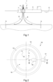
- FIG. 1 illustrates an installation for exploiting energy 1, in particular fluids and for example hydrocarbons or gas, on an offshore platform, allowing the exploitation of hydrocarbon fields at sea 2.
- This installation also called a floating production, storage and unloading unit, can be provided with a ship 3 which is mobile, due to its environment formed by the sea 2, and with a mooring turret 4 which is geostationary and around which the ship 3 is mobile.
- the mooring turret 4 can for example be mechanically secured to the seabed 2 via underwater anchors 5.
- the ship 3 can be movable with respect to the mooring turret 4 by means of a bearing mechanism 7.
- the installation 1 can be provided with conduits 6 which form a network of underwater pipes allowing fluid communication for the transfer of fluid between an underwater deposit then the mooring turret 4, and the ship 3.
- the fluid circulating in the conduits 6 comes from the bottom of the sea 2.
- the installation 1 includes a rotating joint device 10 ensuring the seal between the ship 3 and the mooring turret 4 and the integrity of the transfer of fluids.
- the rotating joint device 10 can be formed of a rotating joint (“ swivel device ” in Anglo-Saxon terminology) or of a stack of such joints (“ swivel stack device ” in Anglo-Saxon terminology).
- such a rotating joint device 10 is generally annular and comprises a first annular part 11, called fixed, which is configured to be secured to the mooring turret 4, as well as a second annular part 12, called mobile, which is configured to be attached to the ship 3.
- the second annular part 12 is movable in rotation relative to the first annular part 11, via a bearing member 13 at least partially interposed between the first and second annular parts 11 and 12.
- the rotary joint device 10 has an internal space 14 defined here by an internal surface 15 of the first annular part 11.
- the installation 1 further comprises a transfer conduit 16 connected, directly or indirectly, to at least one of the underwater conduits 6.
- the transfer conduit 16 enters the rotating joint device 10 through its internal space 14 and emerges outside the rotating joint device 10 through an outlet connection 17.
- the transfer conduit 16 thus passes through the rotating joint device 10 while entering the first annular part 11 and exiting through the second annular part 12.
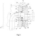
- FIG. 3 shows in section the rotary joint device 10 of the figure 2 and illustrates in more detail the fluid path through the rotary joint device 10 and the cooperation between the first and second annular parts 11 and 12.
- the rotary joint device 10 is provided with a transfer chamber 18 formed partially by a first orifice 19 formed in the first annular part 11 and by a second orifice 20 formed in the second annular part 12 and at least partially facing the first orifice 19.
- the transfer chamber 18 is here annular, or toroidal.
- the first orifice 19 opens at the level of the internal surface 15 of the first annular part 11 into a first portion of the transfer conduit 16 located in the internal space 14 of the rotary joint device 10 and which is connected to the underwater conduits 6.
- the second orifice 20 opens at an external surface 21 of the second annular part 12 into a second portion of the transfer conduit 16 located outside the rotary joint device 10 and which includes the outlet connection 17.
- An arrow illustrated on the Figure 3 shows the fluid path taken by the fluid coming from the conduits 6 and conveyed by the transfer conduit 16 passing through the first and second annular parts 11 and 12 of the rotary joint device 10, up to the outlet connection 17.
- the rotary joint device 10 is further provided with a spacing space 22 located between the first annular part 11 and the second annular part 12.
- the spacing space 22 is provided to allow the rotation of the second annular part 12 relative to the first annular part 11.
- the spacing space 22 is interrupted by the transfer chamber 18.
- the spacing space 22 extends from the rolling member 13 until it opens into the chamber of transfer 18; while on a lower portion 24 of the rotary joint device 10, the spacing space 22 opens at one end into the transfer chamber 18 and opens at an end opposite to the exterior of the rotary joint device 10.
- the transfer chamber 18 is here interposed between the upper 23 and lower 24 portions.
- the spacing space 22 is provided between an external surface of the first annular part 11, which external surface is opposite its internal surface 15, and an internal surface of the second annular part 12, which internal surface is opposite on its external surface 21.
- the rotating joint device 10 comprises dynamic sealing members 30 housed at least partially inside the spacing space 22, in the upper and lower portions 23 and 24 of the rotating joint device 10.
- These dynamic sealing members 30 are intended to seal the spacing space 22.
- These dynamic sealing members 30 may for example include lips whose function is to ensure sealing against the fluid.
- three dynamic sealing members 30 are housed at least partially inside the spacing space 22 in the upper portion 23 of the rotary seal device 10 and three dynamic sealing members 30 are housed at least partially inside the spacing space 22 in the lower portion 24 of the rotary joint device 10.
- the rotary joint device 10 here also comprises several protection devices 35 for the dynamic sealing members 30.
- a protection device 35 is housed at least partially inside the spacing space 22 in the upper portion 23 of the rotating joint device 10 and two protection devices 35 are housed at least partially inside. inside the spacing space 22 in the lower portion 24 of the rotary joint device 10.
- the rotary joint device 10 may also include a cleaning device 50 configured to evacuate debris which said fluid may contain and which is here formed by a channel formed in the second annular part 12 and which opens into the spacing space 22 at level of a protection device 35.
- a cleaning device 50 configured to evacuate debris which said fluid may contain and which is here formed by a channel formed in the second annular part 12 and which opens into the spacing space 22 at level of a protection device 35.
- THE figures 4 to 8 illustrate a dynamic sealing member 30 according to an exemplary embodiment of the present invention.
- a dynamic sealing member 30 is generally generally annular in a free state.
- the axis X therefore represents here an axis of revolution of the dynamic sealing member 30.
- FIG. 4 shows, in section, the dynamic sealing member 30.
- the section shown Figure 4 corresponds to a section taken along a plane radial to the X axis.
- the dynamic sealing member 30 comprises a heel 31 and at least one first lip 32 which extends projecting from the heel 30.
- it further comprises a second lip 38 which also extends projecting from the heel 30, opposite the first lip 32.
- the heel 31 has an internal face 33, oriented towards the axis X, and an external face 34 from which the first and second lips 32, 38 extend.
- the heel 31 On either side, the heel 31 has an upper side surface 135 and a lower side surface 236 connecting the internal face 33 to the external face 34.
- the dynamic sealing member 30 here comprises a reinforcing tab 37.
- the reinforcing tab 37 extends projecting from the external face 34 of the heel 31, at a distance from the edges of the external face 34, i.e. at a distance from the upper 135 and lower 236 side surfaces, and even here substantially in the middle of the face external 34.
- the reinforcing tab 37 is arranged between the first lip 32 and the second lip 38, and at an equal distance from the first lip 32 and the second lip 38.
- the heel 31 has at least one edge located between the internal face 33 of the heel 31 and at least one of the upper lateral surface 135, or of the lower lateral surface 236, of the heel 31, which edge comprises at minus a chamfer or rounding 39.
- At least one internal edge of the heel 31, or even the two internal edges, is (are) chamfered or rounded.
- the dynamic sealing member 30 here comprises two parts 130, 230, designated for convenience first part 130 and second part 230.
- the dynamic sealing member is therefore here formed of two parts 130, 230 which are distinct from each other.
- the first part 130 and the second part 230 are here symmetrical with respect to a median plane of the dynamic sealing member 30.
- the heel 31 of the dynamic sealing member 30 comprises a first heel part 131 and a second heel part 231.
- the first part 130 comprises the first heel part 131 of the heel 31, as well as the first lip 32 which extends projecting from said first heel part 131
- the second part 230 comprises the second heel part 231 of the heel 31, as well as the second lip 38 which extends projecting from said second heel part.
- the reinforcing tab 37 also comprises two parts 137, 237, the first part 130 of the dynamic sealing member 30 comprising the first part 137 of the reinforcing tab 37 while the second part 230 of the dynamic sealing member 30 comprises the second part 237 of the reinforcing tab 37.
- FIG. 5 shows in more detail, in section, the first part 130 of the dynamic sealing member 30.
- the first heel part 131 comprises an internal face 133 which is a first part of the internal face 33 of the dynamic sealing member 30, an external face 134, which is a first part of the external face 34 of the member dynamic sealing 30, from which the first lip 32 extends, as well as the upper lateral surface 135 connecting on one side, called upper, the internal face 133 and the external face 134.
- the first heel part 131 comprises a lower surface 136 configured to bear against the second part 230 of the dynamic sealing member 30 .
- the first part 137 of the reinforcing tab 37 extends more particularly from the internal face 134, in an extension of the lower surface 136.
- At least part of the tab 137 differs from the first lip 32 in that it has a greater thickness, and therefore greater rigidity.
- the first lip 32 of the dynamic sealing member 30 comprises a root 321 by which it is connected to the heel 31, and more particularly here to the first heel part 131, and a free edge 322 opposite the root 321.
- the free edge 322 is here provided with a circumferential bead 323.
- Circumferential indicates that the bead 323 goes around the dynamic sealing member 30, here along the free edge 323 of the first lip 32.
- the bead 323 is here formed on one face of the first lip 32, in particular on the side of its upper face, i.e. on the face located in an extension of the upper lateral surface 135.
- circumferential bead 323 here has a radial notch 324.
- Radial means that the notch extending from a center of the dynamic sealing member, i.e. along a radial plane relative to the X axis.
- the notch 324 is therefore here orthogonal to the free edge 322 of the first lip 32.
- the internal surface 133 of the first heel part 131 is also substantially chamfered or rounded at its edge formed between the internal face 133 and the lower surface 136.
- the second part 230 being symmetrical to the first part 130, the description above is identical for the second part 230 and will not be repeated in detail.
- the references are the same added by 100 and the following description of the arrangement of the dynamic sealing member 30 in a housing 400 will refer to the first part 130 and the second part 230.
- the second movable annular part 12 comprises a housing 400 in which the dynamic sealing member 30 is received at least partially.
- the housing 400 comprises a side wall 401 forming a bearing surface, and a bottom 403.
- the housing is for example a groove hollowed out, here in the second movable annular part 12, from an internal face of the second movable annular part which defines, with an external face of the first fixed annular part, the space of spacing 22.
- An intersection edge between the side wall 401 and the internal face of the second movable annular part 12 thus forms an edge 402 of the housing 400.
- the dynamic sealing member 30 is received in the housing 400 as illustrated figures 7 and 8 .
- the internal face 33 of the heel 31 is here in contact with the first fixed annular part 11. Furthermore here, the housing 400 is arranged so that the heel 31 is received in a position generally orthogonal to the axis of rotation X and the first lip extends generally to the right of the heel.
- the upper side surface 135 and the lower side surface 236 then bear against the wall 401 of the housing 400.
- the side wall 401 of the housing forms a surface on which at least part of the first lip 32 and the second lip 38 come into contact, and in particular at least the circumferential bead 323, it being understood that the second lip 38 can be identical, by symmetry, to the first lip 32 and can therefore also be provided with such a bead, possibly also provided with a notch.
- the radial notch thus allows a passage of fluid which would be introduced into the housing 400, on either side of the circumferential bead 323.
- the pressurized fluid P is configured to activate the dynamic sealing member 30, for example to initiate the initial sealing.
- the dynamic sealing member 30 when the dynamic sealing member 30 is inserted, at least partially, in the housing 400, with at least the first lip 32 towards the bottom 403 of the housing 400, as illustrated figures 7 and 8 , the upper side surface 135 and/or the lower side surface 236 is located in the immediate vicinity of the edge 402 of the housing 400.
- the chamfer or rounding 39 is preferably configured so that the edge 402 is located at least at one limit of the chamfer or rounding 39, at the level of the upper side surface 135 or lower 236 of the heel.
- the edge 402 is out of contact with the upper lateral surface 135 or lower 236 of the heel.
- the spacing space 22 increases with the pressure between said first fixed annular part 11 and said second movable annular part 12, and the spacing space 22 reduces when this pressure decreases between the first fixed annular part 11 and the second part movable ring 12.
- the pressure P in the housing can cause a bead to form from the heel of the dynamic sealing member, which could become pinched when the spacing space 22 is reduced.
- a risk of forming a bulge in the spacing space 22 is limited or even avoided, and consequently a risk of the bead finding itself pinched, or even crushed, between the first fixed annular part 11 and the second movable annular part 12, is also reduced, or even avoided.
- the housing 400 including a dynamic sealing member 30 comprising all or part of the characteristics described above can be located in the rotary joint device as illustrated Figure 3 near the transfer chamber 18.
- the dynamic sealing member 30, in such an arrangement, ensures sealing of the transfer chamber.
- the dynamic sealing member can be used elsewhere in the rotary joint device.
- it can be used to seal a guide mechanism of the first and second annular parts, which mechanism is generally formed by rolling members. We will say that it is a bearing seal.
- It can also serve as an environmental seal, i.e. it is located furthest from the transfer chamber, for example towards one end of the first fixed annular part and/or the second movable annular part, opposite the transfer chamber.
Landscapes
- Engineering & Computer Science (AREA)
- General Engineering & Computer Science (AREA)
- Mechanical Engineering (AREA)
- Chemical & Material Sciences (AREA)
- Combustion & Propulsion (AREA)
- Ocean & Marine Engineering (AREA)
- Joints Allowing Movement (AREA)
- Organic Low-Molecular-Weight Compounds And Preparation Thereof (AREA)
Applications Claiming Priority (1)
| Application Number | Priority Date | Filing Date | Title |
|---|---|---|---|
| FR2210182A FR3140660A1 (fr) | 2022-10-05 | 2022-10-05 | Dispositif joint tournant d’une installation d’exploitation de fluides, type plateforme offshore, et installation comportant un tel dispositif |
Publications (1)
| Publication Number | Publication Date |
|---|---|
| EP4350178A1 true EP4350178A1 (de) | 2024-04-10 |
Family
ID=84887665
Family Applications (1)
| Application Number | Title | Priority Date | Filing Date |
|---|---|---|---|
| EP23201718.6A Pending EP4350178A1 (de) | 2022-10-05 | 2023-10-04 | Drehgelenkanordnung einer offshore-plattform-energieanlage und anlage mit einer solchen vorrichtung |
Country Status (4)
| Country | Link |
|---|---|
| US (1) | US20240117906A1 (de) |
| EP (1) | EP4350178A1 (de) |
| CA (1) | CA3215334A1 (de) |
| FR (1) | FR3140660A1 (de) |
Citations (4)
| Publication number | Priority date | Publication date | Assignee | Title |
|---|---|---|---|---|
| DE19916107A1 (de) * | 1999-04-09 | 2000-10-26 | Mohammad Mohsen Saadat | Dichtung für Druckmittelzuführungen während einer Relativbewegung zweier Teile |
| US20120146293A1 (en) * | 2009-08-19 | 2012-06-14 | Robert Bosch Gmbh | Spring-elastic axial seal |
| EP3460296A1 (de) | 2017-09-21 | 2019-03-27 | Euro Techniques Industries | Dynamische abdichtungsvorrichtung |
| DE102017122269A1 (de) * | 2017-09-26 | 2019-03-28 | Schaeffler Technologies AG & Co. KG | Dichtungsanordnung, insbesondere für Radialgelenklager |
-
2022
- 2022-10-05 FR FR2210182A patent/FR3140660A1/fr active Pending
-
2023
- 2023-10-04 CA CA3215334A patent/CA3215334A1/en active Pending
- 2023-10-04 EP EP23201718.6A patent/EP4350178A1/de active Pending
- 2023-10-04 US US18/481,049 patent/US20240117906A1/en active Pending
Patent Citations (4)
| Publication number | Priority date | Publication date | Assignee | Title |
|---|---|---|---|---|
| DE19916107A1 (de) * | 1999-04-09 | 2000-10-26 | Mohammad Mohsen Saadat | Dichtung für Druckmittelzuführungen während einer Relativbewegung zweier Teile |
| US20120146293A1 (en) * | 2009-08-19 | 2012-06-14 | Robert Bosch Gmbh | Spring-elastic axial seal |
| EP3460296A1 (de) | 2017-09-21 | 2019-03-27 | Euro Techniques Industries | Dynamische abdichtungsvorrichtung |
| DE102017122269A1 (de) * | 2017-09-26 | 2019-03-28 | Schaeffler Technologies AG & Co. KG | Dichtungsanordnung, insbesondere für Radialgelenklager |
Also Published As
| Publication number | Publication date |
|---|---|
| US20240117906A1 (en) | 2024-04-11 |
| CA3215334A1 (en) | 2024-04-05 |
| FR3140660A1 (fr) | 2024-04-12 |
Similar Documents
| Publication | Publication Date | Title |
|---|---|---|
| CA2714625C (fr) | Support flottant equipe de touret comprenant des paliers de roulement hors d'eau | |
| EP0148807B1 (de) | Schutz für Rohrgewinde und Rohrverbindungskontaktflächen | |
| EP3317578B1 (de) | Befestigen eines rohres in einem gehäuse | |
| EP3788292A1 (de) | Lager- und / oder transportbehälter für eine für ein schiff bestimmte flüssiggasladung | |
| FR3041603A1 (fr) | Cuve etanche et isolante disposee dans un navire | |
| EP3719374B1 (de) | Drehgelenkvorrichtung, die für die ausstattung einer anlage zur nutzung von fluiden geeignet ist, insbesondere auf einer offshore-plattform | |
| EP1148207A1 (de) | Verbindungsvorrichtung für eine Unterwasser-Flüssigkeitstransportleitung | |
| FR2914349A1 (fr) | Interface distributeur couronne a aubes/support pour turbine a vapeur | |
| EP3460297A1 (de) | Dynamische abdichtungsvorrichtung | |
| EP3574240B1 (de) | Verbinder mit flansch zur begrenzung der knickausbreitung mit einem differenzdruckventil für unterwasserflüssigkeitstransportrohr | |
| EP4350178A1 (de) | Drehgelenkanordnung einer offshore-plattform-energieanlage und anlage mit einer solchen vorrichtung | |
| EP3460296A1 (de) | Dynamische abdichtungsvorrichtung | |
| EP4306836A1 (de) | Drehgelenkanordnung einer anlage zum betrieb von fluiden, insbesondere auf einer offshore-plattform, und eine solche anlage | |
| EP3665414B1 (de) | Abgedichteter und wärmeisolierender tank | |
| EP3645933B1 (de) | Fluiddichte membran und verfahren zur montage einer fluiddichten membran | |
| WO2015162384A2 (fr) | Dispositif d'attache pour lignes subaquatiques | |
| EP4081726B1 (de) | Isolierabdeckung für ein unterwasserelement einer einrichtung zur verwendung von flüssigkeit in einem wasserabschnitt, zugehörige anlage und verfahren | |
| EP2182266A1 (de) | Dichtungssystem mit Dichtung für Rohrklemme mit Aufnahmemittel und Klemme | |
| EP4306295A1 (de) | Verfahren zur herstellung eines rohlings für einen gegenstand, insbesondere einen dynamischen dichtungsrohling, konfiguriert für eine drehverbindung einer fluidtechnischen anlage, insbesondere offshore-plattform | |
| FR2673263A1 (fr) | Ensemble formant joint pour raccordement souple entre deux elements. | |
| FR3137866A1 (fr) | Procédé de fabrication par soudage d’un organe d’étanchéité dynamique, configuré pour équiper un dispositif joint tournant d’une installation d’exploitation de fluides, notamment sur une plateforme offshore | |
| OA19104A (fr) | Pièce de jonction à bride de limitation de propagation d'écrasement comprenant une soupape de pression différentielle pour conduite sous-marine de transport de fluides. | |
| OA20778A (fr) | Système de Protection de l'embouchure d'une canalisation et Procédé de mise en œuvre d'un tel système. | |
| EP3678928A1 (de) | Schwimmende struktur mit einem tank zur aufnahme von verflüssigtem brenngas | |
| FR2816025A1 (fr) | Clapet d'entree d'air |
Legal Events
| Date | Code | Title | Description |
|---|---|---|---|
| PUAI | Public reference made under article 153(3) epc to a published international application that has entered the european phase |
Free format text: ORIGINAL CODE: 0009012 |
|
| STAA | Information on the status of an ep patent application or granted ep patent |
Free format text: STATUS: THE APPLICATION HAS BEEN PUBLISHED |
|
| AK | Designated contracting states |
Kind code of ref document: A1 Designated state(s): AL AT BE BG CH CY CZ DE DK EE ES FI FR GB GR HR HU IE IS IT LI LT LU LV MC ME MK MT NL NO PL PT RO RS SE SI SK SM TR |
|
| STAA | Information on the status of an ep patent application or granted ep patent |
Free format text: STATUS: REQUEST FOR EXAMINATION WAS MADE |