EP4350178A1 - Rotary joint device of an energy exploitation installation, such as an offshore platform, and installation comprising such a device - Google Patents
Rotary joint device of an energy exploitation installation, such as an offshore platform, and installation comprising such a device Download PDFInfo
- Publication number
- EP4350178A1 EP4350178A1 EP23201718.6A EP23201718A EP4350178A1 EP 4350178 A1 EP4350178 A1 EP 4350178A1 EP 23201718 A EP23201718 A EP 23201718A EP 4350178 A1 EP4350178 A1 EP 4350178A1
- Authority
- EP
- European Patent Office
- Prior art keywords
- heel
- lip
- sealing member
- joint device
- dynamic sealing
- Prior art date
- Legal status (The legal status is an assumption and is not a legal conclusion. Google has not performed a legal analysis and makes no representation as to the accuracy of the status listed.)
- Pending
Links
- 238000009434 installation Methods 0.000 title claims abstract description 31
- 238000007789 sealing Methods 0.000 claims abstract description 95
- 125000006850 spacer group Chemical group 0.000 claims abstract 2
- 239000012530 fluid Substances 0.000 claims description 32
- 239000011324 bead Substances 0.000 claims description 19
- 230000003014 reinforcing effect Effects 0.000 claims description 17
- 229930195733 hydrocarbon Natural products 0.000 claims description 9
- 150000002430 hydrocarbons Chemical class 0.000 claims description 9
- 230000005611 electricity Effects 0.000 claims description 6
- 239000004215 Carbon black (E152) Substances 0.000 claims description 3
- 101100420946 Caenorhabditis elegans sea-2 gene Proteins 0.000 description 3
- 238000004519 manufacturing process Methods 0.000 description 3
- 238000005096 rolling process Methods 0.000 description 3
- 230000015572 biosynthetic process Effects 0.000 description 2
- 238000004140 cleaning Methods 0.000 description 2
- 230000007613 environmental effect Effects 0.000 description 2
- 238000003860 storage Methods 0.000 description 2
- 230000000295 complement effect Effects 0.000 description 1
- 238000005520 cutting process Methods 0.000 description 1
- 230000007423 decrease Effects 0.000 description 1
- SYHGEUNFJIGTRX-UHFFFAOYSA-N methylenedioxypyrovalerone Chemical compound C=1C=C2OCOC2=CC=1C(=O)C(CCC)N1CCCC1 SYHGEUNFJIGTRX-UHFFFAOYSA-N 0.000 description 1
- 230000002787 reinforcement Effects 0.000 description 1
- 230000000284 resting effect Effects 0.000 description 1
- XLYOFNOQVPJJNP-UHFFFAOYSA-N water Substances O XLYOFNOQVPJJNP-UHFFFAOYSA-N 0.000 description 1
Images

Classifications
-
- F—MECHANICAL ENGINEERING; LIGHTING; HEATING; WEAPONS; BLASTING
- F16—ENGINEERING ELEMENTS AND UNITS; GENERAL MEASURES FOR PRODUCING AND MAINTAINING EFFECTIVE FUNCTIONING OF MACHINES OR INSTALLATIONS; THERMAL INSULATION IN GENERAL
- F16L—PIPES; JOINTS OR FITTINGS FOR PIPES; SUPPORTS FOR PIPES, CABLES OR PROTECTIVE TUBING; MEANS FOR THERMAL INSULATION IN GENERAL
- F16L27/00—Adjustable joints, Joints allowing movement
- F16L27/08—Adjustable joints, Joints allowing movement allowing adjustment or movement only about the axis of one pipe
- F16L27/0804—Adjustable joints, Joints allowing movement allowing adjustment or movement only about the axis of one pipe the fluid passing axially from one joint element to another
-
- F—MECHANICAL ENGINEERING; LIGHTING; HEATING; WEAPONS; BLASTING
- F16—ENGINEERING ELEMENTS AND UNITS; GENERAL MEASURES FOR PRODUCING AND MAINTAINING EFFECTIVE FUNCTIONING OF MACHINES OR INSTALLATIONS; THERMAL INSULATION IN GENERAL
- F16J—PISTONS; CYLINDERS; SEALINGS
- F16J15/00—Sealings
- F16J15/16—Sealings between relatively-moving surfaces
- F16J15/32—Sealings between relatively-moving surfaces with elastic sealings, e.g. O-rings
- F16J15/3204—Sealings between relatively-moving surfaces with elastic sealings, e.g. O-rings with at least one lip
- F16J15/3232—Sealings between relatively-moving surfaces with elastic sealings, e.g. O-rings with at least one lip having two or more lips
- F16J15/3236—Sealings between relatively-moving surfaces with elastic sealings, e.g. O-rings with at least one lip having two or more lips with at least one lip for each surface, e.g. U-cup packings
-
- B—PERFORMING OPERATIONS; TRANSPORTING
- B63—SHIPS OR OTHER WATERBORNE VESSELS; RELATED EQUIPMENT
- B63B—SHIPS OR OTHER WATERBORNE VESSELS; EQUIPMENT FOR SHIPPING
- B63B21/00—Tying-up; Shifting, towing, or pushing equipment; Anchoring
- B63B21/50—Anchoring arrangements or methods for special vessels, e.g. for floating drilling platforms or dredgers
- B63B21/507—Anchoring arrangements or methods for special vessels, e.g. for floating drilling platforms or dredgers with mooring turrets
-
- F—MECHANICAL ENGINEERING; LIGHTING; HEATING; WEAPONS; BLASTING
- F16—ENGINEERING ELEMENTS AND UNITS; GENERAL MEASURES FOR PRODUCING AND MAINTAINING EFFECTIVE FUNCTIONING OF MACHINES OR INSTALLATIONS; THERMAL INSULATION IN GENERAL
- F16J—PISTONS; CYLINDERS; SEALINGS
- F16J15/00—Sealings
- F16J15/002—Sealings comprising at least two sealings in succession
-
- F—MECHANICAL ENGINEERING; LIGHTING; HEATING; WEAPONS; BLASTING
- F16—ENGINEERING ELEMENTS AND UNITS; GENERAL MEASURES FOR PRODUCING AND MAINTAINING EFFECTIVE FUNCTIONING OF MACHINES OR INSTALLATIONS; THERMAL INSULATION IN GENERAL
- F16J—PISTONS; CYLINDERS; SEALINGS
- F16J15/00—Sealings
- F16J15/16—Sealings between relatively-moving surfaces
- F16J15/32—Sealings between relatively-moving surfaces with elastic sealings, e.g. O-rings
- F16J15/3204—Sealings between relatively-moving surfaces with elastic sealings, e.g. O-rings with at least one lip
Landscapes
- Engineering & Computer Science (AREA)
- General Engineering & Computer Science (AREA)
- Mechanical Engineering (AREA)
- Chemical & Material Sciences (AREA)
- Combustion & Propulsion (AREA)
- Ocean & Marine Engineering (AREA)
- Joints Allowing Movement (AREA)
- Organic Low-Molecular-Weight Compounds And Preparation Thereof (AREA)
Abstract
Dispositif joint tournant (10) d'une installation d'exploitation d'énergie comportant une première partie annulaire (11) qui est assujettie à une tourelle d'amarrage fixe de ladite installation, une deuxième partie annulaire mobile (12) en rotation autour d'un axe de rotation (X) et par rapport à ladite première partie annulaire fixe (11) et qui est assujettie à un navire mobile de ladite installation, et au moins un organe d'étanchéité dynamique (30) logé à l'intérieur d'un espace d'écartement (22) situé entre ladite première partie annulaire fixe (11) et ladite deuxième partie annulaire mobile (12) et pourvu d'un talon et d'au moins une première lèvre qui s'étend en saillie depuis le talon ; et installation (1) d'exploitation d'énergie comportant un tel dispositif joint tournant (10).Rotating joint device (10) of an energy exploitation installation comprising a first annular part (11) which is secured to a fixed mooring turret of said installation, a second movable annular part (12) rotating around 'an axis of rotation (X) and with respect to said first fixed annular part (11) and which is secured to a mobile vessel of said installation, and at least one dynamic sealing member (30) housed inside 'a spacer space (22) located between said first fixed annular part (11) and said second movable annular part (12) and provided with a heel and at least one first lip which extends projecting from the heel ; and energy exploitation installation (1) comprising such a rotating joint device (10).
Description
L'invention concerne les installations d'exploitation d'énergie, notamment de fluides et par exemple d'hydrocarbures ou de gaz, ou d'électricité, sur des plateformes du type offshore, et notamment les dispositifs joint tournant utilisés dans de telles installations.The invention relates to installations for exploiting energy, in particular fluids and for example hydrocarbons or gas, or electricity, on platforms of the offshore type, and in particular the rotary joint devices used in such installations.
Les dispositifs joint tournant installés dans des installations sous pression peuvent, entre autres, trouver une application dans les navires de production pétrolières du domaine de l'offshore, permettant l'exploitation de champs d'hydrocarbures en mer. Des unités flottantes de production, de stockage et de déchargement peuvent être formées par un navire qui est mobile, du fait de son environnement, autour d'une tourelle d'amarrage qui est géostationnaire. Le navire peut être assujetti temporairement à la tourelle. Les installations peuvent comporter des conduits qui forment un réseau de canalisations subaquatiques et qui permettent une communication fluidique pour un transfert de fluide entre le fond de la mer et le navire.Rotary joint devices installed in pressure installations can, among other things, find application in oil production vessels in the offshore sector, allowing the exploitation of hydrocarbon fields at sea. Floating production units, storage and unloading can be formed by a ship which is mobile, due to its environment, around a mooring turret which is geostationary. The ship can be temporarily secured to the turret. The installations may include conduits which form a network of underwater pipes and which allow fluid communication for fluid transfer between the seabed and the vessel.
Pour assurer l'étanchéité entre le navire et la tourelle et ainsi assurer l'intégrité du transfert de fluide, les dispositifs joint tournant sont pourvus d'une première partie, dite fixe, assujettie à la tourelle et d'une deuxième partie, dite mobile, assujettie au navire. La deuxième partie des dispositifs joint tournant est donc mobile en rotation par rapport à la première partie des dispositifs joint tournant. Les dispositifs joint tournant sont en outre pourvus de plusieurs organes d'étanchéité dynamique, dits joints dynamiques, disposés dans des espaces ménagés entre la première partie fixe et la deuxième partie mobile des dispositifs joint tournant. De tels organes d'étanchéité dynamique peuvent comporter par exemple des lèvres ayant pour fonction d'assurer l'étanchéité face au fluide.To ensure sealing between the ship and the turret and thus ensure the integrity of the fluid transfer, the rotating joint devices are provided with a first part, called fixed, secured to the turret and a second part, called mobile , attached to the ship. The second part of the rotary joint devices is therefore movable in rotation relative to the first part of the rotary joint devices. The rotary joint devices are further provided with several dynamic sealing members, called dynamic seals, arranged in spaces provided between the first fixed part and the second movable part of the rotary joint devices. Such dynamic sealing members may include, for example, lips whose function is to ensure sealing against the fluid.
On connaît de la demande de brevet
L'invention concerne un dispositif joint tournant d'une installation d'exploitation d'énergie, notamment de fluides et par exemple d'hydrocarbures ou de gaz, ou d'électricité, notamment sur une plateforme offshore, qui soit particulièrement performant tout en étant simple, commode et économique.The invention relates to a rotating joint device for an installation for exploiting energy, in particular fluids and for example hydrocarbons or gas, or electricity, in particular on an offshore platform, which is particularly efficient while being simple, convenient and economical.
L'invention a ainsi pour objet, sous un premier aspect, un dispositif joint tournant d'une installation d'exploitation d'énergie, notamment de fluides et par exemple d'hydrocarbures ou de gaz, ou d'électricité, notamment sur une plateforme offshore, comportant une première partie annulaire qui est assujettie à une tourelle d'amarrage fixe de ladite installation, une deuxième partie annulaire mobile en rotation autour d'un axe de rotation X et par rapport à ladite première partie annulaire fixe et qui est assujettie à un navire mobile de ladite installation, et au moins un organe d'étanchéité dynamique logé à l'intérieur d'un espace d'écartement situé entre ladite première partie annulaire fixe et ladite deuxième partie annulaire mobile et pourvu d'un talon et d'au moins une première lèvre qui s'étend en saillie depuis le talon.The subject of the invention is therefore, in a first aspect, a rotating joint device for an installation for exploiting energy, in particular fluids and for example hydrocarbons or gas, or electricity, in particular on a platform offshore, comprising a first annular part which is secured to a fixed mooring turret of said installation, a second annular part movable in rotation around an axis of rotation a mobile vessel of said installation, and at least one dynamic sealing member housed inside a spacing space located between said first fixed annular part and said second movable annular part and provided with a heel and at least one first lip which extends projecting from the heel.
Un tel dispositif joint tournant comporte donc une première partie annulaire, dite fixe, et une deuxième partie annulaire, dite mobile, et la deuxième partie annulaire est mobile en rotation autour d'un axe de rotation X et par rapport à ladite première partie annulaire fixe.Such a rotating joint device therefore comprises a first annular part, called fixed, and a second annular part, called movable, and the second annular part is movable in rotation around an axis of rotation X and with respect to said first fixed annular part .
Un tel dispositif joint tournant comporte en outre au moins un organe d'étanchéité dynamique, lequel est logé à l'intérieur d'un espace d'écartement situé entre ladite première partie annulaire et ladite deuxième partie annulaire. L'au moins un organe d'étanchéité dynamique est notamment pourvu d'un talon et d'au moins une première lèvre qui s'étend en saillie depuis le talon.Such a rotary joint device further comprises at least one dynamic sealing member, which is housed inside a spacing space located between said first annular part and said second annular part. The at least one dynamic sealing member is notably provided with a heel and at least one first lip which extends projecting from the heel.
De plus, la première partie annulaire fixe est assujettie à une tourelle d'amarrage fixe de l'installation d'exploitation d'énergie, et la deuxième partie annulaire mobile est assujettie à un navire mobile de ladite installation d'exploitation d'énergie.In addition, the first fixed annular part is secured to a fixed mooring turret of the energy exploitation installation, and the second movable annular part is secured to a mobile vessel of said energy exploitation installation.
Selon une caractéristique intéressante, l'organe d'étanchéité dynamique comporte deux parties, une première des deux parties de l'organe d'étanchéité dynamique comporte au moins une première partie de talon et la première lèvre qui s'étend en saillie depuis ladite première partie de talon, et une deuxième des deux parties de l'organe d'étanchéité dynamique comporte au moins une deuxième partie de talon.According to an interesting characteristic, the dynamic sealing member comprises two parts, a first of the two parts of the dynamic sealing member comprises at least a first heel part and the first lip which extends projecting from said first heel part, and a second of the two parts of the dynamic sealing member comprises at least a second heel part.
Former l'organe d'étanchéité dynamique en deux parties, avec deux parties de talon distinctes, permet de limiter les phénomènes d'endommagement du talon, qui peuvent mener à une rupture du talon.Forming the dynamic sealing member in two parts, with two distinct heel parts, makes it possible to limit the phenomena of damage to the heel, which can lead to breakage of the heel.
L'organe d'étanchéité dynamique est donc formé de deux parties distinctes l'une de l'autre.The dynamic sealing member is therefore formed of two parts distinct from each other.
Selon un exemple intéressant, la première partie du talon et la deuxième partie du talon sont symétriques.According to an interesting example, the first part of the heel and the second part of the heel are symmetrical.
Par exemple, la première partie de l'organe d'étanchéité dynamique et la deuxième partie de l'organe d'étanchéité dynamique sont symétriques.For example, the first part of the dynamic sealing member and the second part of the dynamic sealing member are symmetrical.
Selon une caractéristique intéressante, l'organe d'étanchéité dynamique comporte au moins une patte de renfort.According to an interesting characteristic, the dynamic sealing member comprises at least one reinforcing tab.
Une telle patte peut également être désignée nervure, ou renfort.Such a tab can also be referred to as a rib, or reinforcement.
La patte de renfort est configurée pour limiter des contraintes de cisaillement dans le talon.The reinforcing tab is configured to limit shear stresses in the heel.
Par exemple, la patte de renfort s'étend en saillie depuis une face externe du talon, à distance des bords de la face externe.For example, the reinforcing tab extends projecting from an external face of the heel, at a distance from the edges of the external face.
Par exemple, la patte de renfort s'étend sensiblement au milieu de la face externe.For example, the reinforcing tab extends substantially in the middle of the external face.
Par exemple, la patte de renfort s'étend en saillie en regard d'au moins la première lèvre. Dans le cadre d'un organe d'étanchéité dynamique en deux parties, la patte de renfort comporte par exemple au moins une partie qui s'étend en saillie depuis la première partie du talon, à distance et en regard d'au moins la première lèvre.For example, the reinforcing tab extends projecting opposite at least the first lip. In the context of a dynamic sealing member in two parts, the reinforcing tab comprises for example at least one part which extends projecting from the first part of the heel, at a distance and facing at least the first lip.
Selon une caractéristique intéressante, la première lèvre de l'organe d'étanchéité dynamique comporte une racine par laquelle elle est raccordée au talon, et un bord libre opposé à la racine, le bord libre étant pourvu d'un bourrelet circonférentiel. Circonférentiel désigne un bourrelet faisant le tour de l'organe d'étanchéité dynamique, i.e. longeant le bord libre de la première lèvre, étant rappelé qu'un tel organe d'étanchéité dynamique est généralement globalement annulaire dans un état libre.According to an interesting characteristic, the first lip of the dynamic sealing member comprises a root by which it is connected to the heel, and a free edge opposite the root, the free edge being provided with a circumferential bead. Circumferential designates a bead going around the dynamic sealing member, i.e. running along the free edge of the first lip, it being remembered that such a dynamic sealing member is generally generally annular in a free state.
Le bourrelet est par exemple formé sur une face de la première lèvre configurée pour être en appui sur une paroi d'un logement recevant au moins en partie l'organe d'étanchéité dynamique.The bead is for example formed on one face of the first lip configured to rest on a wall of a housing receiving at least in part the dynamic sealing member.
Par exemple, le bourrelet circonférentiel comporte une encoche radiale.For example, the circumferential bead has a radial notch.
Radial désigne ici une encoche s'étendant depuis un centre de l'organe d'étanchéité dynamique.Radial here designates a notch extending from a center of the dynamic sealing member.
L'encoche est donc par exemple orthogonale au bord libre de la première lèvre.The notch is therefore, for example, orthogonal to the free edge of the first lip.
L'encoche radiale est par exemple configurée pour équilibrer une pression de fluide qui serait introduit dans le logement, de part et d'autre du bourrelet circonférentiel. L'encoche permet ainsi un équilibre isostatique.The radial notch is for example configured to balance a pressure of fluid which would be introduced into the housing, on either side of the circumferential bead. The notch thus allows isostatic balance.
Un tel fluide sous pression est configuré pour activer l'organe d'étanchéité dynamique, par exemple pour initier l'étanchéité de départ. Il remplace par exemple un ressort couramment utilisé pour plaquer la première lèvre contre une paroi du logement dans lequel elle est insérée.Such a pressurized fluid is configured to activate the dynamic sealing member, for example to initiate initial sealing. For example, it replaces a spring commonly used to press the first lip against a wall of the housing in which it is inserted.
Selon une caractéristique intéressante, au moins une arête entre une face interne du talon, opposée à une face externe depuis laquelle s'étend au moins la première lèvre, et une surface latérale du talon en contact avec une paroi du logement dans lequel est inséré au moins en partie le talon, comporte au moins un chanfrein ou un arrondi.According to an interesting characteristic, at least one edge between an internal face of the heel, opposite an external face from which at least the first lip extends, and a lateral surface of the heel in contact with a wall of the housing in which the less partly the heel, has at least one chamfer or rounding.
Autrement dit, au moins une arête interne du talon est chanfreinée ou arrondie.In other words, at least one internal edge of the heel is chamfered or rounded.
Ainsi, par exemple lorsque l'organe d'étanchéité dynamique est inséré, au moins partiellement, dans un logement, avec au moins la première lèvre vers un fond du logement, une arête du logement arrive sur une surface latérale, supérieure ou inférieure, du talon de l'organe d'étanchéité dynamique.Thus, for example when the dynamic sealing member is inserted, at least partially, in a housing, with at least the first lip towards a bottom of the housing, an edge of the housing arrives on a side surface, upper or lower, of the heel of the dynamic sealing member.
Grâce à la forme arrondie ou chanfreinée de l'arête interne du talon, un risque de formation d'un bourrelet, lorsque l'espace d'écartement situé entre ladite première partie annulaire fixe et ladite deuxième partie annulaire mobile se réduit, est limité voire évité, et un risque que le bourrelet se retrouve pincé, voire écrasé, entre la première partie annulaire fixe et la deuxième partie annulaire mobile, est également réduit, voire évité. Le chanfrein ou l'arrondi est par exemple configuré pour que l'arête se situe au moins à une limite du chanfrein ou de l'arrondi, au niveau de la surface latérale, lorsque l'organe d'étanchéité dynamique est placé dans le logement, et que l'espace d'écartement est à son maximum.Thanks to the rounded or chamfered shape of the internal edge of the heel, a risk of formation of a bead, when the spacing space located between said first fixed annular part and said second movable annular part is reduced, is limited or even avoided, and a risk of the bead finding itself pinched, or even crushed, between the first fixed annular part and the second movable annular part, is also reduced, or even avoided. The chamfer or rounding is for example configured so that the edge is located at least at one limit of the chamfer or rounding, at the level of the lateral surface, when the dynamic sealing member is placed in the housing , and that the spacing space is at its maximum.
Ainsi par exemple, l'arête est hors de contact avec la surface latérale du talon.For example, the edge is out of contact with the lateral surface of the heel.
Il est donc possible de limiter, voire éviter, un risque de formation d'un bourrelet par une partie du talon lorsque l'espace d'écartement se réduit et/ou un risque que l'arête entaille l'organe d'étanchéité dynamique.It is therefore possible to limit, or even avoid, a risk of formation of a bead by part of the heel when the spacing space is reduced and/or a risk of the edge cutting into the dynamic sealing member.
Par ailleurs, une surface du talon en contact avec la paroi du logement est alors réduite. Il est ainsi possible de maximiser une pression sur l'organe d'étanchéité dynamique et donc produire une meilleure étanchéité.Furthermore, a surface of the heel in contact with the wall of the housing is then reduced. It is thus possible to maximize pressure on the dynamic sealing member and therefore produce better sealing.
Les caractéristiques intéressantes décrites ci-dessus peuvent être considérées comme des aspects de l'invention originaux en soi, mais peuvent aussi être combinées, en tout ou parties.The interesting features described above can be considered original aspects of the invention in themselves, but can also be combined, in whole or in part.
Selon un exemple de réalisation, l'organe d'étanchéité dynamique comporte une deuxième lèvre.According to an exemplary embodiment, the dynamic sealing member comprises a second lip.
Par exemple, la deuxième lèvre s'étend en saillie depuis la deuxième partie du talon. Par exemple, la deuxième lèvre s'étend en regard de la première lèvre.For example, the second lip extends projecting from the second part of the heel. For example, the second lip extends opposite the first lip.
Si l'organe d'étanchéité dynamique comporte une patte de renfort, celle-ci est par exemple disposée entre la première lèvre et la deuxième lèvre.If the dynamic sealing member comprises a reinforcing tab, this is for example arranged between the first lip and the second lip.
Par exemple, elle est disposée à égale distance de la première lèvre et de la deuxième lèvre.For example, it is placed equidistant from the first lip and the second lip.
Selon un exemple de réalisation, au moins l'une de la première partie annulaire fixe ou de la deuxième partie annulaire mobile comporte le logement dans lequel est reçu au moins partiellement l'organe d'étanchéité dynamique.According to an exemplary embodiment, at least one of the first fixed annular part or the second movable annular part comprises the housing in which the dynamic sealing member is at least partially received.
Le logement est par exemple une gorge creusée dans au moins l'une de la première partie annulaire fixe ou de la deuxième partie annulaire mobile, à partir d'une face de la première partie annulaire fixe ou de la deuxième partie annulaire mobile, entre lesquelles est défini l'espace d'écartement.The housing is for example a groove dug in at least one of the first fixed annular part or the second movable annular part, from one face of the first fixed annular part or the second movable annular part, between which the spacing space is defined.
Par exemple, la face interne du talon est en contact avec une paroi du logement, i.e. en appui contre une paroi du logement.For example, the internal face of the heel is in contact with a wall of the housing, i.e. resting against a wall of the housing.
Selon un exemple de réalisation, la face interne du talon est en contact avec la première partie annulaire fixe.According to an exemplary embodiment, the internal face of the heel is in contact with the first fixed annular part.
Par exemple, le logement est formé, au moins en partie, dans la deuxième partie annulaire mobile.For example, the housing is formed, at least in part, in the second movable annular part.
Selon un exemple de réalisation, une paroi du logement forme une portée sur laquelle vient en contact au moins une partie de la première lèvre, et notamment au moins le bourrelet circonférentiel.According to an exemplary embodiment, a wall of the housing forms a surface on which at least part of the first lip comes into contact, and in particular at least the circumferential bead.
Selon un exemple de réalisation, le logement est agencé de sorte que le talon est reçu dans une position globalement orthogonale à l'axe de rotation et la première lèvre s'étend globalement au droit du talon.According to an exemplary embodiment, the housing is arranged so that the heel is received in a position generally orthogonal to the axis of rotation and the first lip extends generally to the right of the heel.
Selon un exemple de mise en oeuvre, le dispositif joint tournant comporte au moins une chambre de transfert au moins partiellement ménagée dans ladite première partie annulaire fixe et/ou dans ladite deuxième partie annulaire mobile pour permettre un transfert de fluide au travers dudit dispositif joint tournant, avec l'espace d'écartement qui débouche dans ladite au moins une chambre de transfert, et avec l'organe d'étanchéité dynamique disposé à proximité de la chambre de transfert.According to an example of implementation, the rotary joint device comprises at least one transfer chamber at least partially provided in said first fixed annular part and/or in said second movable annular part to allow a transfer of fluid through said rotary joint device , with the spacing space which opens into said at least one transfer chamber, and with the dynamic sealing member arranged near the transfer chamber.
L'organe d'étanchéité dynamique, dans une telle disposition, assure une étanchéité de la chambre de transfert.The dynamic sealing member, in such an arrangement, ensures sealing of the transfer chamber.
Selon un autre exemple de mise en oeuvre, l'organe d'étanchéité dynamique peut être utilisé ailleurs dans le dispositif joint tournant.According to another example of implementation, the dynamic sealing member can be used elsewhere in the rotary joint device.
Par exemple, il peut servir pour étancher un mécanisme de guidage des première et deuxième parties annulaires, lequel mécanisme est formé généralement par des organes à roulements. On dira qu'il s'agit d'un joint de roulement.For example, it can be used to seal a guiding mechanism of the first and second annular parts, which mechanism is generally formed by rolling members. We will say that it is a bearing seal.
Il peut servir aussi comme joint environnemental, i.e. qu'il est situé au plus loin de la chambre de transfert, par exemple vers une extrémité de la première partie annulaire fixe et/ou de la deuxième partie annulaire mobile, à l'opposé de la chambre de transfert. L'invention a aussi pour objet, sous un autre aspect, une installation d'exploitation d'énergie, notamment de fluides et par exemple d'hydrocarbures ou de gaz, ou d'électricité, et notamment sur une plateforme offshore, comportant au moins un dispositif joint tournant tel que décrit ci-dessus.It can also serve as an environmental seal, i.e. it is located furthest from the transfer chamber, for example towards one end of the first fixed annular part and/or the second movable annular part, opposite the transfer chamber. The invention also relates, in another aspect, to an installation for exploiting energy, in particular fluids and for example hydrocarbons or gas, or electricity, and in particular on an offshore platform, comprising at least a rotary joint device as described above.
Un telle installation d'exploitation d'électricité comporte par exemple un parc éolien. Un fluide circulant dans le dispositif joint tournant comporte alors par exemple de l'eau, du gaz, de l'huile ou autre.Such an electricity exploitation installation includes, for example, a wind farm. A fluid circulating in the rotary joint device then comprises, for example, water, gas, oil or the like.
L'invention, selon un exemple de réalisation, sera bien comprise et ses avantages apparaitront mieux à la lecture de la description détaillée qui suit, donnée à titre indicatif et nullement limitatif, en référence aux dessins annexés dans lesquels :
- La
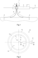
figure 1 représente schématiquement et partiellement une installation d'exploitation d'énergie, notamment de fluides et par exemple d'hydrocarbures ou de gaz, sur une plateforme offshore, pourvue d'un navire, d'une tourelle d'amarrage, d'un réseau de canalisations subaquatiques permettant une communication fluidique pour le transfert du fluide entre le fond de la mer et le navire, et d'un dispositif joint tournant assurant l'étanchéité entre le navire et la tourelle et l'intégrité du transfert de fluides. - La
figure 2 est une vue de dessus du dispositif joint tournant de l'installation illustrée sur lafigure 1 . - La
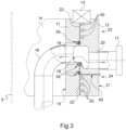
figure 3 est une vue partielle en coupe du dispositif joint tournant, repérée III-III sur lafigure 2 . - La
figure 4 représente schématiquement une section d'un organe d'étanchéité dynamique selon un exemple de réalisation de l'invention. - La
figure 5 représente schématiquement une section d'une première partie d'un organe d'étanchéité dynamique selon un exemple de réalisation de l'invention. - La
figure 6 est une vue en perspective de la première partie d'un organe d'étanchéité dynamique de lafigure 5 . - La
figure 7 représente une partie d'un dispositif selon un exemple de réalisation de l'invention comportant un organe d'étanchéité dynamique selon un exemple de réalisation de l'invention, disposé dans un logement du dispositif joint tournant, dans un état de repos. - La
figure 8 représente la partie de dispositif de lafigure 7 avec une pression appliquée dans le logement.
- There
figure 1 schematically and partially represents an installation for exploiting energy, in particular fluids and for example hydrocarbons or gas, on an offshore platform, provided with a ship, a mooring turret, a network of underwater pipes allowing fluid communication for the transfer of fluid between the seabed and the ship, and a rotating joint device ensuring sealing between the ship and the turret and the integrity of the fluid transfer. - There
figure 2 is a top view of the rotary joint device of the installation illustrated on thefigure 1 . - There
Figure 3 is a partial sectional view of the rotating joint device, marked III-III on thefigure 2 . - There
Figure 4 schematically represents a section of a dynamic sealing member according to an exemplary embodiment of the invention. - There
Figure 5 schematically represents a section of a first part of a dynamic sealing member according to an exemplary embodiment of the invention. - There
Figure 6 is a perspective view of the first part of a dynamic sealing member of theFigure 5 . - There
Figure 7 represents a part of a device according to an exemplary embodiment of the invention comprising a dynamic sealing member according to an exemplary embodiment of the invention, arranged in a housing of the rotary joint device, in a rest state. - There
figure 8 represents the device part of theFigure 7 with pressure applied in the housing.
La
Cette installation 1, aussi appelée unité flottante de production, de stockage et de déchargement, peut être pourvue d'un navire 3 qui est mobile, du fait de son environnement formé par la mer 2, et d'une tourelle d'amarrage 4 qui est géostationnaire et autour de laquelle le navire 3 est mobile.This
La tourelle d'amarrage 4 peut par exemple être assujettie mécaniquement au fond de la mer 2 via des ancres sous-marines 5.The
Le navire 3 peut être mobile vis-à-vis de la tourelle d'amarrage 4 par le biais d'un mécanisme à roulements 7.The
L'installation 1 peut être pourvue de conduits 6 qui forment un réseau de canalisations subaquatiques permettant une communication fluidique pour le transfert du fluide entre un gisement sous-marin puis la tourelle d'amarrage 4, et le navire 3.The
Le fluide circulant dans les conduits 6 provient du fond de la mer 2.The fluid circulating in the
L'installation 1 comporte un dispositif joint tournant 10 assurant l'étanchéité entre le navire 3 et la tourelle d'amarrage 4 et l'intégrité du transfert de fluides.The
Le dispositif joint tournant 10 peut être formé d'un joint tournant (« swivel device » en terminologie anglo-saxonne) ou d'un empilement de tels joints (« swivel stack device » en terminologie anglo-saxonne).The rotating
Ainsi qu'illustré sur la
Dans l'exemple décrit, la deuxième partie annulaire 12 est mobile en rotation par rapport à la première partie annulaire 11, par l'intermédiaire d'un organe à roulements 13 au moins partiellement interposé entre les première et deuxième parties annulaires 11 et 12.In the example described, the second
Le dispositif joint tournant 10 présente un espace interne 14 défini ici par une surface interne 15 de la première partie annulaire 11.The rotary
L'installation 1 comporte en outre un conduit de transfert 16 raccordé, directement ou indirectement, à au moins un des conduits subaquatiques 6.The
Le conduit de transfert 16 entre dans le dispositif jointtournant 10 par son espace interne 14 et débouche à l'extérieur du dispositif joint tournant 10 par un raccord de sortie 17. Le conduit de transfert 16 traverse ainsi le dispositif joint tournant 10 en entrant dans la première partie annulaire 11 et en sortant par la deuxième partie annulaire 12.The
La
Le dispositif joint tournant 10 est pourvu d'une chambre de transfert 18 formée partiellement par un premier orifice 19 ménagé dans la première partie annulaire 11 et par un deuxième orifice 20 ménagé dans la deuxième partie annulaire 12 et au moins partiellement en regard du premier orifice 19.The rotary
La chambre de transfert 18 est ici annulaire, ou toroïdale.The
Le premier orifice 19 débouche au niveau de la surface interne 15 de la première partie annulaire 11 dans une première portion du conduit de transfert 16 située dans l'espace interne 14 du dispositif joint tournant 10 et qui est raccordée aux conduits subaquatiques 6.The
Le deuxième orifice 20 débouche au niveau d'une surface externe 21 de la deuxième partie annulaire 12 dans une deuxième portion du conduit de transfert 16 située à l'extérieur du dispositif joint tournant 10 et qui comporte le raccord de sortie 17.The
Une flèche illustrée sur la
Le dispositif joint tournant 10 est en outre pourvu d'un espace d'écartement 22 situé entre la première partie annulaire 11 et la deuxième partie annulaire 12.The rotary
L'espace d'écartement 22 est prévu pour permettre la rotation de la deuxième partie annulaire 12 par rapport à la première partie annulaire 11.The
Dans l'exemple décrit, l'espace d'écartement 22 est interrompu par la chambre de transfert 18.In the example described, the
Ainsi, sur une portion supérieure 23 du dispositif joint tournant 10, l'espace d'écartement 22 s'étend depuis l'organe à roulement 13 jusqu'à déboucher dans la chambre de transfert 18 ; tandis que sur une portion inférieure 24 du dispositif joint tournant 10, l'espace d'écartement 22 débouche à une extrémité dans la chambre de transfert 18 et débouche à une extrémité opposée à l'extérieur du dispositif joint tournant 10.Thus, on an
La chambre de transfert 18 est ici interposée entre les portions supérieure 23 et inférieure 24.The
En particulier, l'espace d'écartement 22 est ménagé entre une surface externe de la première partie annulaire 11, laquelle surface externe est opposée à sa surface interne 15, et une surface interne de la deuxième partie annulaire 12, laquelle surface interne est opposée à sa surface externe 21.In particular, the
Le dispositif joint tournant 10 comporte des organes d'étanchéité dynamique 30 logés au moins partiellement à l'intérieur de l'espace d'écartement 22, dans les portions supérieure et inférieure 23 et 24 du dispositif joint tournant 10.The rotating
Ces organes d'étanchéité dynamique 30 sont prévus pour étancher l'espace d'écartement 22.These
Ces organes d'étanchéité dynamique 30 peuvent comporter par exemple des lèvres ayant pour fonction d'assurer l'étanchéité face au fluide.These
Dans l'exemple décrit, trois organes d'étanchéité dynamique 30 sont logés au moins partiellement à l'intérieur de l'espace d'écartement 22 dans la portion supérieure 23 du dispositif joint tournant 10 et trois organes d'étanchéité dynamique 30 sont logés au moins partiellement à l'intérieur de l'espace d'écartement 22 dans la portion inférieure 24 du dispositif joint tournant 10.In the example described, three
Le dispositif joint tournant 10 comporte ici en outre plusieurs dispositifs de protection 35 des organes d'étanchéité dynamique 30.The rotary
En variante, il pourrait y en avoir plus ou moins et pas nécessairement le même nombre dans les portions supérieure et inférieure.Alternatively, there could be more or less and not necessarily the same number in the upper and lower portions.
Dans l'exemple décrit, un dispositif de protection 35 est logé au moins partiellement à l'intérieur de l'espace d'écartement 22 dans la portion supérieure 23 du dispositif joint tournant 10 et deux dispositifs de protection 35 sont logés au moins partiellement à l'intérieur de l'espace d'écartement 22 dans la portion inférieure 24 du dispositif joint tournant 10.In the example described, a
Le dispositif joint tournant 10 peut aussi comporter un dispositif de nettoyage 50 configuré pour évacuer des débris que peut comporter ledit fluide et qui est ici formé par un canal formé dans la deuxième partie annulaire 12 et qui débouche dans l'espace d'écartement 22 au niveau d'un dispositif de protection 35.The rotary
En variante, il pourrait y avoir plus ou moins de dispositifs de protection et/ou de dispositif de nettoyage, ou ne pas y en avoir.Alternatively, there could be more or less protection devices and/or cleaning devices, or none.
Les
Un organe d'étanchéité dynamique 30 est généralement globalement annulaire dans un état libre.A
L'axe X représente donc ici un axe de révolution de l'organe d'étanchéité dynamique 30.The axis X therefore represents here an axis of revolution of the
La
Comme l'organe d'étanchéité dynamique 30 est globalement annulaire, la section représentée
Dans l'exemple de réalisation présenté sur les
Le talon 31 comporte une face interne 33, orientée vers l'axe X, et une face externe 34 d'où s'étendent les première et deuxième lèvres 32, 38.The
De part et d'autre, le talon 31 comporte une surface latérale supérieure 135 et une surface latérale inférieure 236 reliant la face interne 33 à la face externe 34.On either side, the
Selon une caractéristique intéressante, l'organe d'étanchéité dynamique 30 comporte ici une patte de renfort 37.According to an interesting characteristic, the
La patte de renfort 37 s'étend en saillie depuis la face externe 34 du talon 31, à distance des bords de la face externe 34, i.e. à distance des surfaces latérales supérieure 135 et inférieure 236, et même ici sensiblement au milieu de la face externe 34.The reinforcing
Ici, la patte de renfort 37 est agencée entre la première lèvre 32 et la deuxième lèvre 38, et à égale distance de la première lèvre 32 et de la deuxième lèvre 38.Here, the reinforcing
Selon une autre caractéristique intéressante, le talon 31 présente au moins une arête située entre la face interne 33 du talon 31 et au moins une de la surface latérale supérieure 135, ou de la surface latérale inférieure 236, du talon 31, laquelle arête comporte au moins un chanfrein ou un arrondi 39.According to another interesting characteristic, the
Autrement dit, au moins une arête interne du talon 31, voire les deux arêtes internes, est (sont) chanfreinée(s) ou arrondie(s).In other words, at least one internal edge of the
Selon une autre caractéristique intéressante, l'organe d'étanchéité dynamique 30 comporte ici deux parties 130, 230, désignées par commodité première partie 130 et deuxième partie 230.According to another interesting characteristic, the
L'organe d'étanchéité dynamique est donc ici formé de deux parties 130, 230 qui sont distinctes l'une de l'autre.The dynamic sealing member is therefore here formed of two
La première partie 130 et la deuxième partie 230 sont ici symétriques par rapport à un plan médian de l'organe d'étanchéité dynamique 30.The
Un plan médian désigne ici un plan orthogonal à l'axe X, autrement dit dont l'axe X forme une normale.A median plane here designates a plane orthogonal to the X axis, in other words whose X axis forms a normal.
Par conséquent, le talon 31 de l'organe d'étanchéité dynamique 30 comporte une première partie de talon 131 et une deuxième partie de talon 231.Consequently, the
Ainsi, dans l'exemple illustré, la première partie 130 comporte la première partie de talon 131 du talon 31, ainsi que la première lèvre 32 qui s'étend en saillie depuis ladite première partie de talon 131, et la deuxième partie 230 comporte la deuxième partie de talon 231 du talon 31, ainsi que la deuxième lèvre 38 qui s'étend en saillie depuis ladite deuxième partie de talon.Thus, in the example illustrated, the
Ici, du fait de la structure en deux parties de l'organe d'étanchéité dynamique, la patte de renfort 37 comporte également deux parties 137, 237, la première partie 130 de l'organe d'étanchéité dynamique 30 comportant la première partie 137 de la patte de renfort 37 tandis que la deuxième partie 230 de l'organe d'étanchéité dynamique 30 comporte la deuxième partie 237 de la patte de renfort 37.Here, due to the two-part structure of the dynamic sealing member, the reinforcing
La
La première partie de talon 131 comporte une face interne 133 qui est une première partie de la face interne 33 de l'organe d'étanchéité dynamique 30, une face externe 134, qui est une première partie de la face externe 34 de l'organe d'étanchéité dynamique 30, d'où s'étend la première lèvre 32, ainsi que la surface latérale supérieure 135 reliant d'un côté, dit supérieur, la face interne 133 et la face externe 134.The
Entre la face interne 133 et la face externe 134, et opposée à la surface latérale supérieure 135, la première partie de talon 131 comporte une surface inférieure 136 configurée pour venir en appui contre la deuxième partie 230 de l'organe d'étanchéité dynamique 30. Comme l'illustre la
Au moins une partie de la patte 137 se distingue de la première lèvre 32 en ce qu'elle a une épaisseur, et donc une rigidité, supérieure.At least part of the
Comme le montre mieux la
Le bord libre 322 est ici pourvu d'un bourrelet circonférentiel 323.The
Circonférentiel indique que le bourrelet 323 fait le tour de l'organe d'étanchéité dynamique 30, ici en longeant le bord libre 323 de la première lèvre 32.Circumferential indicates that the
Le bourrelet 323 est ici formé sur une face de la première lèvre 32, en particulier du côté de sa face supérieure, i.e. sur la face située dans un prolongement de la surface latérale supérieure 135.The
En outre, le bourrelet circonférentiel 323 comporte ici une encoche radiale 324.In addition, the
Radial signifie que l'encoche s'étendant depuis un centre de l'organe d'étanchéité dynamique, i.e. selon un plan radial par rapport à l'axe X.Radial means that the notch extending from a center of the dynamic sealing member, i.e. along a radial plane relative to the X axis.
L'encoche 324 est donc ici orthogonale au bord libre 322 de la première lèvre 32. Comme le montre mieux la
La deuxième partie 230 étant symétrique à la première partie 130, la description ci-dessus est identique pour la deuxième partie 230 et ne sera pas reprise en détail. Les références sont les mêmes additionnées de 100 et la description qui suit de l'agencement de l'organe d'étanchéité dynamique 30 dans un logement 400 fera référence à la première partie 130 et à la deuxième partie 230.The
Dans l'exemple de réalisation des
En variante, le logement pourrait être ménagé dans la première partie annulaire fixe. Le logement 400 comporte une paroi latérale 401 formant portée, et un fond 403.Alternatively, the housing could be provided in the first fixed annular part. The
Le logement est par exemple une gorge creusée, ici dans la deuxième partie annulaire mobile 12, à partir d'une face interne de la deuxième partie annulaire mobile qui définit, avec une face externe de la première partie annulaire fixe, l'espace d'écartement 22. Un bord d'intersection entre la paroi latérale 401 et la face interne de la deuxième partie annulaire mobile 12 forme ainsi une arête 402 du logement 400.The housing is for example a groove hollowed out, here in the second movable
L'organe d'étanchéité dynamique 30 est reçu dans le logement 400 comme illustré
La face interne 33 du talon 31 est ici en contact avec la première partie annulaire fixe 11. De plus ici, le logement 400 est agencé de sorte que le talon 31 est reçu dans une position globalement orthogonale à l'axe de rotation X et la première lèvre s'étend globalement au droit du talon.The
La surface latérale supérieure 135 et la surface latérale inférieure 236 sont alors en appui contre la paroi 401 du logement 400.The
La paroi latérale 401 du logement forme une portée sur laquelle vient en contact au moins une partie de la première lèvre 32 et de la deuxième lèvre 38, et notamment au moins le bourrelet circonférentiel 323, étant entendu que la deuxième lèvre 38 peut être identique, par symétrie, à la première lèvre 32 et peut donc également être pourvue d'un tel bourrelet, éventuellement muni d'une encoche également.The
En fonctionnement du dispositif joint tournant, l'encoche radiale permet ainsi un passage de fluide qui serait introduit dans le logement 400, de part et d'autre du bourrelet circonférentiel 323.In operation of the rotating joint device, the radial notch thus allows a passage of fluid which would be introduced into the
Un tel fonctionnement est illustré sur la
Le fluide sous pression P est configuré pour activer l'organe d'étanchéité dynamique 30, par exemple pour initier l'étanchéité de départ.The pressurized fluid P is configured to activate the
Grâce à l'encoche radiale, il n'y a pas nécessairement besoin d'un ressort complémentaire pour plaquer la première lèvre 32, ainsi que la deuxième lèvre 38, contre la paroi 401 du logement 400.Thanks to the radial notch, there is not necessarily a need for a complementary spring to press the
Ainsi, comme l'illustre la
Par ailleurs, lorsque l'organe d'étanchéité dynamique 30 est inséré, au moins partiellement, dans le logement 400, avec au moins la première lèvre 32 vers le fond 403 du logement 400, comme illustré
Lorsque l'espace d'écartement 22 est à son maximum, le chanfrein ou l'arrondi 39 est de préférence configuré pour que l'arête 402 se situe au moins à une limite du chanfrein ou de l'arrondi 39, au niveau de la surface latérale supérieure 135 ou inférieure 236 du talon.When the
Ainsi par exemple, l'arête 402 est hors de contact avec la surface latérale supérieure 135 ou inférieure 236 du talon.So for example, the
Par ailleurs, une surface du talon en contact avec la paroi du logement est alors réduite. Il est ainsi possible de maximiser une pression sur l'organe d'étanchéité dynamique et donc produire une meilleure étanchéité.Furthermore, a surface of the heel in contact with the wall of the housing is then reduced. It is thus possible to maximize pressure on the dynamic sealing member and therefore produce better sealing.
L'espace d'écartement 22 augmente avec la pression entre ladite première partie annulaire fixe 11 et ladite deuxième partie annulaire mobile 12, et l'espace d'écartement 22 réduit lorsque cette pression diminue entre la première partie annulaire fixe 11 et la deuxième partie annulaire mobile 12.The
Lorsque l'espace d'écartement 22 augmente, la pression P dans le logement peut engendrer une formation d'un bourrelet à partir du talon de l'organe d'étanchéité dynamique, lequel pourrait se retrouver pincé lorsque l'espace d'écartement 22 se réduit. Dans le présent exemple de réalisation selon l'invention, grâce à l'arrondi ou chanfrein 39 de l'arête interne du talon 31, un risque de formation d'un bourrelet dans l'espace d'écartement 22 est limité voire évité, et par conséquent un risque que le bourrelet se retrouve pincé, voire écrasé, entre la première partie annulaire fixe 11 et la deuxième partie annulaire mobile 12, est également réduit, voire évité.When the
On notera aussi que grâce à la forme sensiblement chanfreinée ou arrondie de la surface interne 133 de la première partie de talon 131 en son arête formée entre la face interne 133 et la surface inférieure 136, respectivement de la surface interne de la deuxième partie de talon 231 en son arête formée entre la face interne et la surface inférieure, les risques d'accrochage entre les deux parties de l'organe d'étanchéité dynamique 30 lorsqu'elles sont insérées dans le logement 400 sont réduits.It will also be noted that thanks to the substantially chamfered or rounded shape of the
Le logement 400 incluant un organe d'étanchéité dynamique 30 comportant tout ou partie des caractéristiques décrites ci-dessus peut être situé dans le dispositif joint tournant tel qu'illustré
L'organe d'étanchéité dynamique 30, dans une telle disposition, assure une étanchéité de la chambre de transfert.The
Selon un autre exemple de mise en oeuvre, l'organe d'étanchéité dynamique peut être utilisé ailleurs dans le dispositif joint tournant.According to another example of implementation, the dynamic sealing member can be used elsewhere in the rotary joint device.
Par exemple, il peut servir pour étancher un mécanisme de guidage des première et deuxième parties annulaires, lequel mécanisme est formé généralement par des organes à roulements. On dira qu'il s'agit d'un joint de roulement.For example, it can be used to seal a guide mechanism of the first and second annular parts, which mechanism is generally formed by rolling members. We will say that it is a bearing seal.
Il peut servir aussi comme joint environnemental, i.e. qu'il est situé au plus loin de la chambre de transfert, par exemple vers une extrémité de la première partie annulaire fixe et/ou de la deuxième partie annulaire mobile, à l'opposé de la chambre de transfert.It can also serve as an environmental seal, i.e. it is located furthest from the transfer chamber, for example towards one end of the first fixed annular part and/or the second movable annular part, opposite the transfer chamber.
Claims (11)
caractérisé en ce que l'organe d'étanchéité dynamique (30) comporte deux parties (130, 230), une première (130) des deux parties de l'organe d'étanchéité dynamique (30) comportant au moins une première partie de talon (131) du talon (31) et la première lèvre (32) qui s'étend en saillie depuis ladite première partie de talon (131), et une deuxième (230) des deux parties de l'organe d'étanchéité dynamique (30) comportant au moins une deuxième partie de talon (231) du talon (31).Rotating joint device (10) of an energy exploitation installation, in particular on an offshore platform, comprising a first annular part (11) which is secured to a fixed mooring turret of said installation, a second movable annular part (12) in rotation around an axis of rotation (X) and relative to said first fixed annular part (11) and which is secured to a mobile vessel of said installation, and at least one dynamic sealing member (30) ) housed inside a spacer space (22) located between said first fixed annular part (11) and said second movable annular part (12) and provided with a heel (31) and at least one first lip (32) which extends projecting from the heel (31),
characterized in that the dynamic sealing member (30) comprises two parts (130, 230), a first (130) of the two parts of the dynamic sealing member (30) comprising at least a first heel part (131) of the heel (31) and the first lip (32) which extends projecting from said first heel part (131), and a second (230) of the two parts of the dynamic sealing member (30 ) comprising at least a second heel portion (231) of the heel (31).
Applications Claiming Priority (1)
| Application Number | Priority Date | Filing Date | Title |
|---|---|---|---|
| FR2210182A FR3140660A1 (en) | 2022-10-05 | 2022-10-05 | Rotating joint device for a fluid exploitation installation, offshore platform type, and installation comprising such a device |
Publications (1)
| Publication Number | Publication Date |
|---|---|
| EP4350178A1 true EP4350178A1 (en) | 2024-04-10 |
Family
ID=84887665
Family Applications (1)
| Application Number | Title | Priority Date | Filing Date |
|---|---|---|---|
| EP23201718.6A Pending EP4350178A1 (en) | 2022-10-05 | 2023-10-04 | Rotary joint device of an energy exploitation installation, such as an offshore platform, and installation comprising such a device |
Country Status (4)
| Country | Link |
|---|---|
| US (1) | US20240117906A1 (en) |
| EP (1) | EP4350178A1 (en) |
| CA (1) | CA3215334A1 (en) |
| FR (1) | FR3140660A1 (en) |
Citations (4)
| Publication number | Priority date | Publication date | Assignee | Title |
|---|---|---|---|---|
| DE19916107A1 (en) * | 1999-04-09 | 2000-10-26 | Mohammad Mohsen Saadat | Seal for pressure medium supply during relative movement of two components has four sealing lips in two pairs for dynamic seal effect, and connecting bores in seal |
| US20120146293A1 (en) * | 2009-08-19 | 2012-06-14 | Robert Bosch Gmbh | Spring-elastic axial seal |
| EP3460296A1 (en) | 2017-09-21 | 2019-03-27 | Euro Techniques Industries | Dynamic sealing device |
| DE102017122269A1 (en) * | 2017-09-26 | 2019-03-28 | Schaeffler Technologies AG & Co. KG | Sealing arrangement, in particular for radial spherical plain bearings |
-
2022
- 2022-10-05 FR FR2210182A patent/FR3140660A1/en active Pending
-
2023
- 2023-10-04 EP EP23201718.6A patent/EP4350178A1/en active Pending
- 2023-10-04 US US18/481,049 patent/US20240117906A1/en active Pending
- 2023-10-04 CA CA3215334A patent/CA3215334A1/en active Pending
Patent Citations (4)
| Publication number | Priority date | Publication date | Assignee | Title |
|---|---|---|---|---|
| DE19916107A1 (en) * | 1999-04-09 | 2000-10-26 | Mohammad Mohsen Saadat | Seal for pressure medium supply during relative movement of two components has four sealing lips in two pairs for dynamic seal effect, and connecting bores in seal |
| US20120146293A1 (en) * | 2009-08-19 | 2012-06-14 | Robert Bosch Gmbh | Spring-elastic axial seal |
| EP3460296A1 (en) | 2017-09-21 | 2019-03-27 | Euro Techniques Industries | Dynamic sealing device |
| DE102017122269A1 (en) * | 2017-09-26 | 2019-03-28 | Schaeffler Technologies AG & Co. KG | Sealing arrangement, in particular for radial spherical plain bearings |
Also Published As
| Publication number | Publication date |
|---|---|
| FR3140660A1 (en) | 2024-04-12 |
| US20240117906A1 (en) | 2024-04-11 |
| CA3215334A1 (en) | 2024-04-05 |
Similar Documents
| Publication | Publication Date | Title |
|---|---|---|
| EP2252501B1 (en) | Floating support having a reel including roller bearings outside the water | |
| EP3788292A1 (en) | Storage and/or transport tank for a liquid gas cargo intended for a vessel | |
| EP3317578B1 (en) | Securing a pipe in a housing | |
| EP0148807A1 (en) | Protector for pipe threads and abutment surfaces | |
| FR3041603A1 (en) | SEALED AND INSULATED TANK DISPOSED IN A SHIP | |
| FR3030682A1 (en) | PIPE ASSEMBLY WITH DRAINAGE SYSTEM | |
| FR3094444A1 (en) | Rotary joint device configured to equip a fluid exploitation installation, in particular on an offshore platform | |
| EP3460297A1 (en) | Dynamic sealing device | |
| EP4350178A1 (en) | Rotary joint device of an energy exploitation installation, such as an offshore platform, and installation comprising such a device | |
| EP3574240B1 (en) | Connector with flange for limiting buckle propagation comprising a differential pressure valve for underwater fluid-transport pipe | |
| EP3460296A1 (en) | Dynamic sealing device | |
| EP4306836A1 (en) | Rotary joint device for a fluid exploitation installation, in particular on an offshore platform, and such an installation | |
| EP3665414B1 (en) | Sealed and thermally insulating tank | |
| WO2015162384A2 (en) | Fastening device for underwater lines | |
| EP4081726B1 (en) | Insulating cover for a submerged element of a facility for using fluid in a stretch of water, associated facility and method | |
| FR3137950A1 (en) | Assembly of rotary joint devices of a fluid exploitation installation, in particular on an offshore platform, and such an installation | |
| EP3645933B1 (en) | Fluidtight membrane and method for assembling a fluidtight membrane | |
| EP2182266A1 (en) | Etancheity system with joint for pipe clamps with pich up means and clamp | |
| EP4306295A1 (en) | Method for manufacturing an article blank, in particular a dynamic seal blank, configured to equip a swivel joint of a fluid exploitation rig | |
| FR2673263A1 (en) | Assembly forming a seal for flexible connection between two elements | |
| FR3137866A1 (en) | Method of manufacturing by welding a dynamic sealing member, configured to equip a rotary joint device of a fluid exploitation installation, in particular on an offshore platform | |
| OA19104A (en) | Crush propagation limitation flange connection piece comprising a differential pressure valve for underwater fluid transport pipe. | |
| OA20778A (en) | Protection system of the mouth of a pipeline and method of implementing such a system. | |
| FR2816025A1 (en) | Sealing system for air inlet valve used to protect water pipe against fluctuations in pressure comprises fixed sealing ring in valve body where it fits against lip of branch pipe and second sealing ring around edge of valve body | |
| FR2865790A1 (en) | Female unit for connecting channels and/or low pressure fluid container, has isolating plug whose extensions have end surfaces that contract with respect to annular transversal section for receiving tubular body of male unit, to open plug |
Legal Events
| Date | Code | Title | Description |
|---|---|---|---|
| PUAI | Public reference made under article 153(3) epc to a published international application that has entered the european phase |
Free format text: ORIGINAL CODE: 0009012 |
|
| STAA | Information on the status of an ep patent application or granted ep patent |
Free format text: STATUS: THE APPLICATION HAS BEEN PUBLISHED |
|
| AK | Designated contracting states |
Kind code of ref document: A1 Designated state(s): AL AT BE BG CH CY CZ DE DK EE ES FI FR GB GR HR HU IE IS IT LI LT LU LV MC ME MK MT NL NO PL PT RO RS SE SI SK SM TR |