EP4350158A1 - Vehicular panel structure - Google Patents
Vehicular panel structure Download PDFInfo
- Publication number
- EP4350158A1 EP4350158A1 EP22810883.3A EP22810883A EP4350158A1 EP 4350158 A1 EP4350158 A1 EP 4350158A1 EP 22810883 A EP22810883 A EP 22810883A EP 4350158 A1 EP4350158 A1 EP 4350158A1
- Authority
- EP
- European Patent Office
- Prior art keywords
- resin
- outer panel
- panel structure
- vehicle
- structure according
- Prior art date
- Legal status (The legal status is an assumption and is not a legal conclusion. Google has not performed a legal analysis and makes no representation as to the accuracy of the status listed.)
- Pending
Links
- 229920005989 resin Polymers 0.000 claims abstract description 237
- 239000011347 resin Substances 0.000 claims abstract description 237
- 239000000463 material Substances 0.000 claims abstract description 49
- 239000000853 adhesive Substances 0.000 claims description 26
- 230000001070 adhesive effect Effects 0.000 claims description 26
- 230000002093 peripheral effect Effects 0.000 claims description 14
- 229920001187 thermosetting polymer Polymers 0.000 claims description 11
- 229920005992 thermoplastic resin Polymers 0.000 claims description 8
- 230000004048 modification Effects 0.000 description 49
- 238000012986 modification Methods 0.000 description 49
- 239000004088 foaming agent Substances 0.000 description 20
- 230000000694 effects Effects 0.000 description 13
- 239000013521 mastic Substances 0.000 description 10
- 229920003051 synthetic elastomer Polymers 0.000 description 10
- 239000005061 synthetic rubber Substances 0.000 description 10
- -1 polyethylene Polymers 0.000 description 8
- 239000013585 weight reducing agent Substances 0.000 description 7
- 230000015572 biosynthetic process Effects 0.000 description 6
- 238000000465 moulding Methods 0.000 description 6
- 238000005507 spraying Methods 0.000 description 6
- 229910000831 Steel Inorganic materials 0.000 description 5
- 238000005516 engineering process Methods 0.000 description 5
- 238000005187 foaming Methods 0.000 description 5
- 229910052751 metal Inorganic materials 0.000 description 5
- 239000002184 metal Substances 0.000 description 5
- 239000007921 spray Substances 0.000 description 5
- 239000010959 steel Substances 0.000 description 5
- UIIMBOGNXHQVGW-UHFFFAOYSA-M Sodium bicarbonate Chemical compound [Na+].OC([O-])=O UIIMBOGNXHQVGW-UHFFFAOYSA-M 0.000 description 4
- PPBRXRYQALVLMV-UHFFFAOYSA-N Styrene Chemical compound C=CC1=CC=CC=C1 PPBRXRYQALVLMV-UHFFFAOYSA-N 0.000 description 4
- 238000000034 method Methods 0.000 description 4
- 239000000047 product Substances 0.000 description 4
- 238000010438 heat treatment Methods 0.000 description 3
- NBOCQTNZUPTTEI-UHFFFAOYSA-N 4-[4-(hydrazinesulfonyl)phenoxy]benzenesulfonohydrazide Chemical compound C1=CC(S(=O)(=O)NN)=CC=C1OC1=CC=C(S(=O)(=O)NN)C=C1 NBOCQTNZUPTTEI-UHFFFAOYSA-N 0.000 description 2
- 239000004156 Azodicarbonamide Substances 0.000 description 2
- BVKZGUZCCUSVTD-UHFFFAOYSA-M Bicarbonate Chemical compound OC([O-])=O BVKZGUZCCUSVTD-UHFFFAOYSA-M 0.000 description 2
- MWRWFPQBGSZWNV-UHFFFAOYSA-N Dinitrosopentamethylenetetramine Chemical compound C1N2CN(N=O)CN1CN(N=O)C2 MWRWFPQBGSZWNV-UHFFFAOYSA-N 0.000 description 2
- 229920002292 Nylon 6 Polymers 0.000 description 2
- 229920002302 Nylon 6,6 Polymers 0.000 description 2
- 239000004696 Poly ether ether ketone Substances 0.000 description 2
- 239000004698 Polyethylene Substances 0.000 description 2
- 239000004743 Polypropylene Substances 0.000 description 2
- 239000004793 Polystyrene Substances 0.000 description 2
- BZHJMEDXRYGGRV-UHFFFAOYSA-N Vinyl chloride Chemical class ClC=C BZHJMEDXRYGGRV-UHFFFAOYSA-N 0.000 description 2
- 125000003118 aryl group Chemical group 0.000 description 2
- XOZUGNYVDXMRKW-AATRIKPKSA-N azodicarbonamide Chemical compound NC(=O)\N=N\C(N)=O XOZUGNYVDXMRKW-AATRIKPKSA-N 0.000 description 2
- 235000019399 azodicarbonamide Nutrition 0.000 description 2
- 238000005452 bending Methods 0.000 description 2
- 239000011248 coating agent Substances 0.000 description 2
- 238000000576 coating method Methods 0.000 description 2
- 238000004070 electrodeposition Methods 0.000 description 2
- 239000003822 epoxy resin Substances 0.000 description 2
- LNEPOXFFQSENCJ-UHFFFAOYSA-N haloperidol Chemical compound C1CC(O)(C=2C=CC(Cl)=CC=2)CCN1CCCC(=O)C1=CC=C(F)C=C1 LNEPOXFFQSENCJ-UHFFFAOYSA-N 0.000 description 2
- 239000013067 intermediate product Substances 0.000 description 2
- 229920006287 phenoxy resin Polymers 0.000 description 2
- 239000013034 phenoxy resin Substances 0.000 description 2
- 239000011295 pitch Substances 0.000 description 2
- 229920001643 poly(ether ketone) Polymers 0.000 description 2
- 229920001652 poly(etherketoneketone) Polymers 0.000 description 2
- 229920006122 polyamide resin Polymers 0.000 description 2
- 229920001230 polyarylate Polymers 0.000 description 2
- 229920001707 polybutylene terephthalate Polymers 0.000 description 2
- 229920000515 polycarbonate Polymers 0.000 description 2
- 239000004417 polycarbonate Substances 0.000 description 2
- 229920000647 polyepoxide Polymers 0.000 description 2
- 229920000728 polyester Polymers 0.000 description 2
- 229920006393 polyether sulfone Polymers 0.000 description 2
- 229920002530 polyetherether ketone Polymers 0.000 description 2
- 229920000573 polyethylene Polymers 0.000 description 2
- 229920000139 polyethylene terephthalate Polymers 0.000 description 2
- 239000005020 polyethylene terephthalate Substances 0.000 description 2
- 229920000098 polyolefin Polymers 0.000 description 2
- 229920001955 polyphenylene ether Polymers 0.000 description 2
- 229920001155 polypropylene Polymers 0.000 description 2
- 229920005990 polystyrene resin Polymers 0.000 description 2
- 229920006395 saturated elastomer Polymers 0.000 description 2
- 229910000030 sodium bicarbonate Inorganic materials 0.000 description 2
- 235000017557 sodium bicarbonate Nutrition 0.000 description 2
- 238000005728 strengthening Methods 0.000 description 2
- 229920001169 thermoplastic Polymers 0.000 description 2
- 239000004416 thermosoftening plastic Substances 0.000 description 2
- 229920006337 unsaturated polyester resin Polymers 0.000 description 2
- 229920001567 vinyl ester resin Polymers 0.000 description 2
- 239000000470 constituent Substances 0.000 description 1
- 230000001747 exhibiting effect Effects 0.000 description 1
- 239000006260 foam Substances 0.000 description 1
- 230000010354 integration Effects 0.000 description 1
- 230000000149 penetrating effect Effects 0.000 description 1
- 230000035515 penetration Effects 0.000 description 1
- 230000002265 prevention Effects 0.000 description 1
- 230000003014 reinforcing effect Effects 0.000 description 1
- 238000003466 welding Methods 0.000 description 1
Images


Classifications
-
- B—PERFORMING OPERATIONS; TRANSPORTING
- B62—LAND VEHICLES FOR TRAVELLING OTHERWISE THAN ON RAILS
- B62D—MOTOR VEHICLES; TRAILERS
- B62D29/00—Superstructures, understructures, or sub-units thereof, characterised by the material thereof
- B62D29/001—Superstructures, understructures, or sub-units thereof, characterised by the material thereof characterised by combining metal and synthetic material
- B62D29/004—Superstructures, understructures, or sub-units thereof, characterised by the material thereof characterised by combining metal and synthetic material the metal being over-moulded by the synthetic material, e.g. in a mould
-
- B—PERFORMING OPERATIONS; TRANSPORTING
- B62—LAND VEHICLES FOR TRAVELLING OTHERWISE THAN ON RAILS
- B62D—MOTOR VEHICLES; TRAILERS
- B62D25/00—Superstructure or monocoque structure sub-units; Parts or details thereof not otherwise provided for
- B62D25/08—Front or rear portions
- B62D25/10—Bonnets or lids, e.g. for trucks, tractors, busses, work vehicles
-
- B—PERFORMING OPERATIONS; TRANSPORTING
- B62—LAND VEHICLES FOR TRAVELLING OTHERWISE THAN ON RAILS
- B62D—MOTOR VEHICLES; TRAILERS
- B62D27/00—Connections between superstructure or understructure sub-units
- B62D27/02—Connections between superstructure or understructure sub-units rigid
- B62D27/026—Connections by glue bonding
-
- B—PERFORMING OPERATIONS; TRANSPORTING
- B62—LAND VEHICLES FOR TRAVELLING OTHERWISE THAN ON RAILS
- B62D—MOTOR VEHICLES; TRAILERS
- B62D29/00—Superstructures, understructures, or sub-units thereof, characterised by the material thereof
- B62D29/001—Superstructures, understructures, or sub-units thereof, characterised by the material thereof characterised by combining metal and synthetic material
- B62D29/005—Superstructures, understructures, or sub-units thereof, characterised by the material thereof characterised by combining metal and synthetic material preformed metal and synthetic material elements being joined together, e.g. by adhesives
-
- F—MECHANICAL ENGINEERING; LIGHTING; HEATING; WEAPONS; BLASTING
- F16—ENGINEERING ELEMENTS AND UNITS; GENERAL MEASURES FOR PRODUCING AND MAINTAINING EFFECTIVE FUNCTIONING OF MACHINES OR INSTALLATIONS; THERMAL INSULATION IN GENERAL
- F16B—DEVICES FOR FASTENING OR SECURING CONSTRUCTIONAL ELEMENTS OR MACHINE PARTS TOGETHER, e.g. NAILS, BOLTS, CIRCLIPS, CLAMPS, CLIPS OR WEDGES; JOINTS OR JOINTING
- F16B5/00—Joining sheets or plates, e.g. panels, to one another or to strips or bars parallel to them
- F16B5/08—Joining sheets or plates, e.g. panels, to one another or to strips or bars parallel to them by means of welds or the like
-
- B—PERFORMING OPERATIONS; TRANSPORTING
- B62—LAND VEHICLES FOR TRAVELLING OTHERWISE THAN ON RAILS
- B62D—MOTOR VEHICLES; TRAILERS
- B62D25/00—Superstructure or monocoque structure sub-units; Parts or details thereof not otherwise provided for
- B62D25/06—Fixed roofs
-
- B—PERFORMING OPERATIONS; TRANSPORTING
- B62—LAND VEHICLES FOR TRAVELLING OTHERWISE THAN ON RAILS
- B62D—MOTOR VEHICLES; TRAILERS
- B62D25/00—Superstructure or monocoque structure sub-units; Parts or details thereof not otherwise provided for
- B62D25/08—Front or rear portions
- B62D25/10—Bonnets or lids, e.g. for trucks, tractors, busses, work vehicles
- B62D25/105—Bonnets or lids, e.g. for trucks, tractors, busses, work vehicles for motor cars
Definitions
- the present invention relates to a vehicle panel structure.
- Priority is claimed on Japanese Patent Application No. 2021-88089, filed on May 26, 2021 , the content of which is incorporated herein by reference.
- the panel rigidity is a feature indicating the resistance to deflection of the outer panel. For example, in a case where an outer panel of a vehicle has high panel rigidity, the outer panel is hardly deflected when being touched.
- Patent Document 1 describes a technology related to a reinforcing structure for a vehicle body obtained by providing an inner sheet over an outer sheet with a foaming layer interposed therebetween, in which the foaming layer is a thermosetting resin foam with an expansion ratio of 1.03 to 1.30 times.
- Patent Document 1 Japanese Unexamined Patent Application, First Publication No. S63-258274
- Patent Document 1 it is said that both high panel rigidity and prevention of the occurrence of strain can be achieved.
- the adhesion to an outer panel in a case where the adhesion to an outer panel is not sufficient, it is not possible to sufficiently exhibit high panel rigidity, and this also acts as a factor hindering the weight reduction.
- the present disclosure is contrived in view of the above-described problems, and an object of the present disclosure is to provide a vehicle panel structure capable of exhibiting excellent panel rigidity while being lightweight.
- the present invention employs the following configurations.
- the resin member is joined to the inner surface of the outer panel member in a state of being firmly held by the inner member, and thus it is possible to exhibit excellent panel rigidity while achieving lightweight properties.
- a vehicle panel structure 100 according to a first embodiment of the present disclosure (hereinafter, simply referred to as the panel structure 100) will be described.
- the panel structure 100 according to the present embodiment is applied to a roof of a vehicle 1000 shown in FIG. 21 .
- FIG. 1 is a perspective view showing the panel structure 100 as viewed from the outside of the vehicle
- FIG. 2 is a perspective view showing the panel structure 100 as viewed from the inside of the vehicle.
- the panel structure 100 has an outer panel member 110, an inner member 120 disposed to face an inner surface of the outer panel member 110, and a resin member 130 joined to the inner surface of the outer panel member 110.
- the outer panel member 110 is a sheet-like member having a curved surface protruding toward the outside of the vehicle.
- the surface on the outside of the vehicle may be referred to as the outer surface
- the surface on the inside of the vehicle may be referred to as the inner surface.
- the outer panel member 110 is formed by press-forming a metal sheet such as a steel sheet.
- the tensile strength of the outer panel member 110 is preferably 440 MPa or greater, and more preferably 590 MPa or greater from the viewpoint of dent resistance.
- the sheet thickness of the outer panel member 110 is preferably 0.55 mm or less, and more preferably 0.50 mm or less from the viewpoint of weight reduction.
- the sheet thickness of the outer panel member 110 is excessively small, the panel rigidity is noticeably reduced. Further, in a case where the sheet thickness of the outer panel member 110 is excessively small, the outer panel member 110 is likely to resonate with high-frequency vibrations. Therefore, for example, in a case where the outer panel member 110 is applied to a roof of a vehicle, sounds such as vibration sounds due to raindrops from above or wind noise during traveling are likely to intrude into the vehicle, and the quietness may be noticeably reduced. Therefore, in order to reliably exhibit excellent panel rigidity and quietness, the sheet thickness of the outer panel member 110 is preferably 0.30 mm or greater, and more preferably 0.35 mm or greater. According to the panel structure 100 of the present embodiment, the panel rigidity of the outer panel member 110 can be increased by a configuration to be described later. Therefore, it is possible to exhibit excellent panel rigidity while reducing the sheet thickness of the outer panel member 110.
- the inner member 120 is a long member disposed to face an inner surface of the outer panel member 110.
- the inner member 120 is disposed so as to extend along one direction in an in-plane direction of the outer panel member 110.
- the inner member 120 functions to reinforce the panel structure 100 by being attached to the outer panel member 110 in such a manner that a longitudinal direction of the inner member 120 coincides with a width direction of the vehicle.
- FIG. 3 is a cross-sectional view showing a cross-section of the inner member 120 perpendicular to the longitudinal direction.
- the inner member 120 has a substantially hat-like cross-section portion including: a top sheet portion 121; a pair of side wall portions 123, 123 bending and extending from both end portions of the top sheet portion 121; and a pair of flange portions 125, 125 bending and extending outward from end portions of the pair of side wall portions 123, 123 on the opposite side to the top sheet portion 121.
- the width direction of the inner member 120 means a direction parallel to the top sheet portion 121 among directions perpendicular to the longitudinal direction of the inner member 120.
- the inner member 120 can be obtained by, for example, press-forming a metal sheet such as a steel sheet.
- the pair of resin members 130, 130 are joined to the inner surface of the outer panel member 110 so as to bury part of the inner member 120.
- the expression "at least part of the inner member is buried in the resin member” means that at least part of the inner member is entered into the resin member and is held in a state of being in surface contact with the resin member.
- a maximum-thickness part having the maximum length in a direction perpendicular to the in-plane direction of the outer panel member 110 of the resin member 130 is preferably 3 mm or greater and 60 mm or less in thickness.
- the thickness of the maximum-thickness part of the resin member 130 is 3 mm or greater, the inner member 120 can be held more firmly. Accordingly, since it is possible to compensate for the lack of rigidity associated with the thinning of the outer panel member 110, the thickness of the maximum-thickness part of the resin member 130 is preferably 3 mm or greater. The thickness of the maximum-thickness part of the resin member 130 is more preferably 5 mm or greater.
- the thickness of the maximum-thickness part of the resin member 130 is preferably 60 mm or less.
- the thickness of the maximum-thickness part of the resin member 130 is more preferably 10 mm or less from the viewpoint of weight reduction.
- the material of the resin member 130 may be a resin, and any of a thermosetting resin and a thermoplastic resin can be used for the resin member 130.
- thermosetting resin examples include epoxy resins, unsaturated polyester resins, and vinyl ester resins.
- thermoplastic resin examples include polyolefins (polyethylene, polypropylene, and the like) and acid-modified products thereof, polyamide resins such as nylon 6 and nylon 66, thermoplastic aromatic polyesters such as polyethylene terephthalate and polybutylene terephthalate, polycarbonates, polyether sulfones, polyphenylene ethers and modified products thereof, polyarylates, polyether ketones, polyether ether ketones, polyether ketone ketones, vinyl chlorides, styrene-based resins such as polystyrene, and phenoxy resins.
- polyolefins polyethylene, polypropylene, and the like
- polyamide resins such as nylon 6 and nylon 66
- thermoplastic aromatic polyesters such as polyethylene terephthalate and polybutylene terephthalate
- polycarbonates such as polyethylene terephthalate and polybutylene terephthalate
- polycarbonates such as polyethylene terephthalate and polybutylene
- the resin may be formed of a plurality of kinds of resin materials.
- the resin material for forming the resin member 130 contains a foaming agent, the work efficiency during attachment of the resin member 130 is improved. Therefore, the resin material for forming the resin member 130 preferably contains a foaming agent.
- foaming agent examples include N,N'-dinitrosopentamethylenetetramine, azodicarbonamide, 4,4' -oxybis(benzenesulfonyl hydrazide), hydrogencarbonate, and sodium hydrogen carbonate.
- the amount of the foaming agent is preferably adjusted so that the expansion ratio is 5 times or greater and 50 times or less.
- the expansion ratio is 5 times or greater, the flange portion 125 of the inner member 120 can be more reliably buried in the resin member 130. Therefore, it is possible to reliably exhibit the panel rigidity improvement effect.
- the vibration is likely to be damped, and thus the quietness improvement effect can be further increased.
- the expansion ratio is more preferably 10 times or greater from the viewpoint of compensating for the lack of rigidity while reducing the weight.
- the expansion ratio is 50 times or less, it is possible to prevent the density of the resin member 130 from being excessively reduced. Therefore, it is possible to reliably exhibit the panel rigidity improvement effect.
- the expansion ratio is 50 times or less, it is possible to prevent the density of the resin member 130 from being excessively reduced, and thus it is possible to enhance the vibration characteristics and further increase the quietness improvement effect.
- the expansion ratio is more preferably 20 times or less.
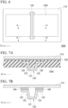
- FIG. 4 is a schematic view for illustrating the positional relationship between the members in a state in which the panel structure 100 is viewed from the inside of the vehicle. As shown in FIG. 4 , the pair of resin members 130, 130 are disposed so as to bury part of the inner member 120 in the longitudinal center of the inner member 120.
- FIG. 5(a) is a cross-sectional view along the arrow A of FIG. 4 . That is, FIG. 5(a) shows a cross-section portion in the longitudinal center of the inner member 120, in the cross-section portion of the panel structure 100 perpendicular to the longitudinal direction of the inner member 120.
- width-directional end portions of the pair of flange portions 125, 125 of the inner member 120 are entered into the pair of resin members 130, 130 from side surfaces of the pair of resin members 130, 130. That is, part of the inner member 120 is buried in the resin member 130.
- upper surfaces of the pair of resin members 130, 130 are joined to the inner surface of the outer panel member 110 via an adhesion portion 150.
- the adhesion portion 150 may be an adhesive.
- a mastic adhesive primarily containing synthetic rubber is used as the material of the adhesion portion 150
- the panel rigidity of the outer panel member 110 can be further increased.
- a mastic adhesive primarily containing synthetic rubber is used as the material of the adhesion portion 150
- the adhesion portion 150 may be provided on only part or all of the upper surface of the resin member 130.
- the resin member 130 can be formed by spray-coating a resin material containing the foaming agent on the outer panel member 110 and/or the inner member 120 and foaming the resin material by heating. In this case, since the upper surface of the resin member 130 is directly joined to the outer panel member 110, the adhesion portion 150 can be omitted.
- FIG. 5(b) is a cross-sectional view along the arrow B of FIG. 4 . That is, FIG. 5(b) shows a cross-section portion on a longitudinal end portion side of the inner member 120, in the cross-section portion of the panel structure 100 perpendicular to the longitudinal direction of the inner member 120.
- the pair of resin members 130, 130 are not disposed, and the pair of flange portions 125, 125 of the inner member 120 are joined to the outer panel member 110 via an adhesion portion 160.
- the adhesion portion 160 may be an adhesive.
- a mastic adhesive primarily containing synthetic rubber is used as the material of the adhesion portion 160
- the panel rigidity of the outer panel member 110 can be further increased.
- a mastic adhesive primarily containing synthetic rubber is used as the material of the adhesion portion 160
- the adhesion portion 160 is provided only on the longitudinal end portion side of the inner member 120 but may also be provided in the longitudinal center portion. In a case where the adhesion portion 160 is also provided in the longitudinal center portion of the inner member 120, the adhesion portion 160 may be continuously provided along the longitudinal direction of the inner member 120, or intermittently provided at predetermined pitches along the longitudinal direction of the inner member 120.
- the adhesion portion 150 joining the outer panel member 110 and the resin member 130 and the adhesion portion 160 joining the outer panel member 110 and the inner member 120 are preferably the same material from the viewpoint of improving the work efficiency during attachment of the inner member 120 and the resin member 130 to the outer panel member 110.
- a molding die is installed so as to surround a predetermined part of the inner member 120, and a resin material is injected into the molding die and hardened to integrate the inner member 120 with the pair of resin members 130, 130.
- a second step A12 the inner member 120 and the pair of resin members 130, 130 integrated with each other are attached to the outer panel member 110 with an adhesive or the like.
- the resin material used in the first step A11 either of a thermoplastic resin and a thermosetting resin can be employed.
- the resin material may contain a foaming agent.
- the resin material may be previously injected into the molding die and hardened to mold intermediate products of the pair of resin members 130, 130, the intermediate products may be subjected to slit working, and the flange portion 125 of the inner member 120 may be inserted into a slit to achieve the integration.
- a resin material containing a foaming agent is spray-coated on the outer panel member 110 and/or the inner member 120.
- a second step B12 the pair of flange portions 125, 125 of the inner member 120 are attached to the outer panel member 110 with an adhesive or the like.
- a third step B13 the resin material is foamed to form the resin members 130 in a state of burying the pair of flange portions 125, 125 of the inner member 120.
- thermosetting resin is used as the resin material to be spray-coated in the first step B11.
- the order of the first step B11 and the second step B12 may be reversed.
- the amount of the foaming agent is preferably adjusted so that the expansion ratio is 5 times or greater and 50 times or less.
- the expansion ratio is 5 times or greater
- the flange portion 125 of the inner member 120 can be more reliably buried in the resin member 130. Therefore, it is possible to reliably exhibit the panel rigidity improvement effect.
- the vibration is likely to be damped, and thus the quietness improvement effect can be further increased.
- the expansion ratio is 50 times or less, it is possible to prevent the density of the resin member 130 from being excessively reduced. Therefore, it is possible to reliably exhibit the panel rigidity improvement effect.
- the expansion ratio is 50 times or less, it is possible to prevent the density of the resin member 130 from being excessively reduced, and thus it is possible to enhance the vibration characteristics and further increase the quietness improvement effect.
- the resin material may be foamed using the heat during electrodeposition coating.
- part of the inner member 120 is buried in the pair of resin members 130, 130. Therefore, the pair of resin members 130, 130 are joined to the inner surface of the outer panel member 110 in a state of being firmly held by the inner member 120.
- the panel rigidity of the outer panel member 110 can be improved compared to a case where the resin member 130 is simply disposed between the outer panel member 110 and the inner member 120. Since the panel rigidity can be improved in this way, it is possible to prevent a reduction in panel rigidity that is noticeable in a case where the thickness of the outer panel member 110 is reduced for weight reduction.
- part of the inner member 120 is buried in the pair of resin members 130, 130. Therefore, the pair of resin members 130, 130 are joined to the inner surface of the outer panel member 110 in a state of being firmly held by the inner member 120. Accordingly, compared to a case where the resin member 130 is simply disposed between the outer panel member 110 and the inner member 120, it is possible to further enhance the vibration characteristics so that high-frequency vibrations are easily damped, whereby the vibration characteristics of the outer panel member 110 can be enhanced, and the quietness can be improved.
- the quietness can be improved in this way, it is possible to prevent a reduction in quietness that is noticeable in a case where the thickness of the outer panel member 110 is reduced for weight reduction.
- roof panel structure 100 it can exhibit excellent quietness while being lightweight.
- the panel structure 100 according to the first embodiment described above is configured to have the pair of resin members 130.
- a panel structure 100A according to a first modification example is configured to have a single resin member 130A.
- FIG. 6 is a schematic view for illustrating the positional relationship between the members in a state in which the panel structure 100A according to the first modification example is viewed from the inside of a vehicle.
- FIG. 7(a) is a cross-sectional view along the arrow C of FIG. 6, and
- FIG. 7(b) is a cross-sectional view along the arrow D of FIG. 6 .
- a pair of flange portions 125, 125 and part of a pair of side wall portions 123 of an inner member 120 are buried in the single resin member 130A. According to the panel structure 100A, a wider part of the inner member 120 can be held by the resin member 130A. Furthermore, since the resin member 130A is also present in a region between the pair of flange portions 125, 125, a wide part of an outer panel member 110 can be joined to the resin member 130A.
- the panel rigidity of the outer panel member 110 can be further increased.
- the vibration characteristics of the outer panel member 110 can be enhanced, and the quietness can be further increased.
- the single resin member 130A may be configured by connecting a plurality of resin members divided.
- a cross-section portion in which an inner member 120 is entirely buried by a single resin member 130B may be provided as in a panel structure 100B according to a second modification example.
- FIG. 8 is a schematic view for illustrating the positional relationship between the members in a state in which the panel structure 100B according to the second modification example is viewed from the inside of a vehicle.
- FIG. 9(a) is a cross-sectional view along the arrow E of FIG. 8
- FIG. 9(b) is a cross-sectional view along the arrow F of FIG. 8 .
- the entire inner member 120 (that is, top sheet portion 121, a pair of side wall portions 123, 123, and a pair of flange portions 125, 125) is buried by the single resin member 130B.
- the cross-section portion in which the inner member 120 is entirely buried in the single resin member 130B is provided, a wider part of the inner member 120 can be held by the resin member 130B. Furthermore, since the resin member 130B is also present in a region between the pair of flange portions 125, 125, a wide part of an outer panel member 110 can be joined to the resin member 130B.
- the panel rigidity of the outer panel member 110 can be further increased.
- the vibration characteristics of the outer panel member 110 can be enhanced, and the quietness can be further increased.
- the single resin member 130B may be configured by connecting a plurality of resin members divided.
- the spray-coating may be performed from a gap between the flange portion 125 and the outer panel member 110.
- holes for spray-coating may be formed in the top sheet portion 121 or the side wall portion 123 of the inner member 120.
- the panel structure 100 according to the first embodiment described above is configured to have a single inner member 120 but may be configured to have a plurality of inner members 120.
- FIG. 10 is a schematic view for illustrating the positional relationship between the members in a state in which a panel structure 100C according to a third modification example is viewed from the inside of a vehicle.
- a first inner member 120C1 and a second inner member 120C2 are disposed so as to be separated from each other in a longitudinal direction of the vehicle. More specifically, the first inner member 120C 1 and the second inner member 120C2 are disposed in such a manner that a longitudinal direction of the first inner member 120C1 and a longitudinal direction of the second inner member 120C2 are parallel to each other.
- the first inner member 120C1 and the second inner member 120C2 are provided with a pair of first resin members 130C1, 130C1 and a pair of second resin members 130C2, 130C2 burying a pair of flange portions 125, 125.
- first inner member 120C1 and the second inner member 120C2 have the same configuration as the inner member 120, and the first resin member 130C1 and the second resin member 130C2 have the same configuration as the resin member 130, description thereof will be omitted.
- the panel structure 100C of the third modification example it is possible to increase the panel rigidity in a desired part even in a case where the outer panel member 110 has large lengths.
- the roof panel structure 100C of the third modification example it is possible to enhance the vibration characteristics and increase the quietness even in a case where the outer panel member 110 has large lengths.
- three or more inner members 120 may be provided, or a plurality of inner members 120 may be provided so that their longitudinal directions intersect each other.
- the first resin member 130C1 and the second resin member 130C2 are disposed to be separated from each other around the center in the longitudinal direction of the vehicle but may be integrated with each other. That is, a configuration in which at least part of each of the pair of inner members 120 adjacent to each other in the longitudinal direction of the vehicle is buried in a single (common) resin member 130 may be adopted.
- each of the pair of resin members 130, 130 is composed of a single member, but each resin member 130 may have a configuration in which a plurality of members divided are connected along the in-plane direction of the outer panel member 110.
- FIG. 11 is a schematic view for illustrating the positional relationship between the members in a state in which a panel structure 100D according to a fourth modification example is viewed from the inside of a vehicle.
- the panel structure 100D has a first resin member 130D1 and a second resin member 130D2 which are two members divided in a longitudinal direction (width direction of vehicle) of an inner member 120 in the in-plane direction of the outer panel member 110.
- the first resin member 130D1 and the second resin member 130D2 are connected by joining an end surface 131D1 of the first resin member 130D1 and an end surface 131D2 of the second resin member 130D2 with an adhesive.
- first resin member 130D1 and the second resin member 130D2 have the same configuration as the resin member 130, description thereof will be omitted.
- the panel structure 100D of the fourth modification example it is possible to increase the panel rigidity in a desired part even in a case where the outer panel member 110 has large lengths.
- the roof panel structure 100D of the fourth modification example it is possible to enhance the vibration characteristics and increase the quietness even in a case where the outer panel member 110 has large lengths.
- FIG. 12 is a schematic view for illustrating the positional relationship between the members in a state in which a panel structure 100E according to a fifth modification example is viewed from the inside of a vehicle.
- the panel structure 100E has a first resin member 130E1 and a second resin member 130E2 which are two members divided in a longitudinal direction (width direction of vehicle) of an inner member 120 in the in-plane direction of the outer panel member 110.
- the first resin member 130E1 and the second resin member 130E2 are connected to each other by engaging an end surface 131E1 of the first resin member 130E1 and an end surface 131E2 of the second resin member 130E2 with each other.
- each of the end surface 131E1 and the end surface 131E2 facing each other has convex portions and concave portions alternately, and the first resin member 130E1 and the second resin member 130E2 are connected by engaging the convex portions and the concave portions of the end surface 131E1 with the concave portions and the convex portions of the end surface 131E2.
- first resin member 130E1 and the second resin member 130E2 have the same configuration as the resin member 130, duplicate description will be omitted.
- the panel structure 100D of the fifth modification example it is possible to increase the panel rigidity in a desired part even in a case where the outer panel member 110 has large lengths.
- the roof panel structure 100D of the fifth modification example it is possible to enhance the vibration characteristics and increase the quietness even in a case where the outer panel member 110 has large lengths.
- the engaging parts between the convex portions and the concave portions are joined with an adhesive, it is possible to more reliably prevent the first resin member 130E1 and the second resin member 130E2 from falling off. Therefore, the engaging parts between the convex portions and the concave portions are preferably joined with an adhesive.
- FIG. 13 is a schematic view showing the positional relationship between the members in a panel structure 100F according to a sixth modification example.
- FIG. 14 is a cross-sectional view along the arrow G of FIG. 13 .
- a pair of side frames 170, 170 are provided near end edges of an outer panel member 110 in a width direction of a vehicle so as to extend in a longitudinal direction of the vehicle.
- the side frame 170 may be, for example, a hollow long member formed of a metal sheet such as a steel sheet.
- both end portions of an inner member 120 in a longitudinal direction are fixed to the pair of side frames 170, 170 by welding or the like.
- both the end portions of the inner member 120 in the longitudinal direction are buried in resin members 130F as shown in FIG. 14 .
- a pair of the resin members 130F, 130F are joined to an inner surface of the outer panel member 110 in a state of being firmly held by the inner member 120, both the end portions of which are fixed to the pair of side frames 170, 170. Therefore, the vibration characteristics of the outer panel member 110 can be enhanced, and the quietness can be further improved.
- the inner member 120 may be a member having a U-shaped cross-section or a member having a T-shaped cross-section.
- the resin member 130 is provided only in part of the inner member 120 in the longitudinal direction, but the resin member 130 may be provided over the whole length of the inner member 120 in the longitudinal direction.
- the resin member 130 can be provided so as to completely surround and bury the inner member 120.
- a vehicle panel structure 200 according to a second embodiment of the present disclosure (hereinafter, simply referred to as the panel structure 200) will be described.
- the panel structure 200 according to the present embodiment is a panel structure applied to a hood of a vehicle 1000 shown in FIG. 21 .
- FIG. 15 is an exploded perspective view of the panel structure 200.
- the panel structure 200 has an outer panel member 210, an inner member 220 disposed to face an inner surface of the outer panel member 210, and a resin member 230 joined to the inner surface of the outer panel member 210.
- the outer panel member 210 is a sheet-like member having a curved surface protruding toward the outside of the vehicle.
- the surface on the outside of the vehicle may be referred to as the outer surface
- the surface on the inside of the vehicle may be referred to as the inner surface.
- the outer panel member 210 is formed by press-forming a metal sheet such as a steel sheet.
- the tensile strength of the outer panel member 210 is preferably 440 MPa or greater, and more preferably 590 MPa or greater from the viewpoint of dent resistance.
- the sheet thickness of the outer panel member 210 is preferably 0.55 mm or less, and more preferably 0.50 mm or less from the viewpoint of weight reduction.
- the sheet thickness of the outer panel member 210 is preferably 0.30 mm or greater, and more preferably 0.35 mm or greater. According to the panel structure 200 of the present embodiment, the panel rigidity of the outer panel member 210 can be increased by a configuration to be described later. Therefore, it is possible to exhibit excellent panel rigidity while reducing the sheet thickness of the outer panel member 210.
- the inner member 220 is composed of a sheet-like main body portion 221 disposed to face the inner surface of the outer panel member 210.
- the main body portion 221 has a protrusion portion 221a protruding toward the outer panel member 210 in the center of the main body portion 221 in an in-plane direction.
- the protrusion portion 221a functions to reinforce the panel structure 200 by being formed on the inner member 220 in such a manner that a longitudinal direction of the protrusion portion 221a coincides with a width direction of the vehicle.
- the protrusion portion 221a may be formed on the inner member 220 in such a manner that the longitudinal direction of the protrusion portion 221a intersects with the width direction of the vehicle when viewed from a direction perpendicular to the in-plane direction of the outer panel member 210.
- the protrusion portion 221a may have a circular, elliptical, or polygonal shape when viewed from the direction perpendicular to the in-plane direction of the outer panel member 210.
- the inner member 220 can be obtained by, for example, press-forming a metal sheet such as a steel sheet.
- the resin member 230 has a bottom surface 231 facing the main body portion 221 of the inner member 220.
- a groove 231a having a shape corresponding to the protrusion portion 221a is formed on the bottom surface 231.
- the resin member 230 is joined to the inner surface of the outer panel member 210 so as to bury a tip end of the protrusion portion 221a on the side of the outer panel member 210.
- a maximum-thickness part having the maximum length in a direction perpendicular to the in-plane direction of the outer panel member 210 is preferably 3 mm or greater and 60 mm or less in thickness.
- the thickness of the maximum-thickness part of the resin member 230 is 3 mm or greater, the inner member 220 can be held more firmly. Accordingly, since it is possible to compensate for the lack of rigidity associated with the thinning of the outer panel member 210, the thickness of the maximum-thickness part of the resin member 230 is preferably 3 mm or greater.
- the thickness of the maximum-thickness part of the resin member 230 is preferably 60 mm or less.
- the material of the resin member 230 may be a resin, and any of a thermosetting resin and a thermoplastic resin can be used as the material of the resin member 230.
- thermosetting resin examples include epoxy resins, unsaturated polyester resins, and vinyl ester resins.
- thermoplastic resin examples include polyolefins (polyethylene, polypropylene, and the like) and acid-modified products thereof, polyamide resins such as nylon 6 and nylon 66, thermoplastic aromatic polyesters such as polyethylene terephthalate and polybutylene terephthalate, polycarbonates, polyether sulfones, polyphenylene ethers and modified products thereof, polyarylates, polyether ketones, polyether ether ketones, polyether ketone ketones, vinyl chlorides, styrene-based resins such as polystyrene, and phenoxy resins.
- polyolefins polyethylene, polypropylene, and the like
- polyamide resins such as nylon 6 and nylon 66
- thermoplastic aromatic polyesters such as polyethylene terephthalate and polybutylene terephthalate
- polycarbonates such as polyethylene terephthalate and polybutylene terephthalate
- polycarbonates such as polyethylene terephthalate and polybutylene
- the resin may be formed of a plurality of kinds of resin materials.
- the resin material for forming the resin member 230 contains a foaming agent, the work efficiency during attachment of the resin member 230 is improved. Therefore, the resin material for forming the resin member 230 preferably contains a foaming agent.
- foaming agent examples include N,N'-dinitrosopentamethylenetetramine, azodicarbonamide, 4,4' -oxybis(benzenesulfonyl hydrazide), hydrogencarbonate, and sodium hydrogen carbonate.
- the amount of the foaming agent is preferably adjusted so that the expansion ratio is 5 times or greater and 50 times or less.
- FIG. 16 is a cross-sectional view along the arrow H of FIG. 15 . That is, FIG. 16 shows a cross-section portion in the longitudinal center of the protrusion portion 221a, in the cross-section portion of the panel structure 200 perpendicular to the longitudinal direction of the protrusion portion 221a.
- a tip end of the protrusion portion 221a of the inner member 220 is entered into the groove 231a of the resin member 230. That is, part of the inner member 220 is buried in the resin member 230.
- an upper surface of the resin member 230 is joined to the inner surface of the outer panel member 210 via an adhesion portion 250.
- the adhesion portion 250 may be an adhesive.
- a mastic adhesive primarily containing synthetic rubber is used as the material of the adhesion portion 250, the panel rigidity of the outer panel member 210 can be further increased. Therefore, as the material of the adhesion portion 250, a mastic adhesive primarily containing synthetic rubber is preferably used.
- the adhesion portion 250 may be provided on only part or all of the upper surface of the resin member 230.
- the resin member 230 can be formed by spray-coating a resin material containing the foaming agent on the outer panel member 210 and/or the inner member 220 and foaming the resin material by heating. In this case, since the upper surface of the resin member 230 is directly joined to the outer panel member 210, the adhesion portion 250 can be omitted.
- a molding die is installed so as to surround a predetermined part of the protrusion portion 221a of the inner member 220, and a resin material is injected into the molding die and hardened to integrate the inner member 220 with the resin member 230.
- a second step A22 the inner member 220 and the resin member 230 integrated with each other are attached to the outer panel member 210 with an adhesive or the like.
- the resin material used in the first step A21 either of a thermoplastic resin and a thermosetting resin can be employed.
- the resin material may contain a foaming agent.
- the resin member 230 and the inner member 220 may be integrated with each other by joining the resin member 230 made previously in the molding die to the inner member 220 with an adhesive or the like.
- a resin material containing a foaming agent is spray-coated on the outer panel member 210 and/or the inner member 220.
- a second step B22 the inner member 220 is assembled to the outer panel member 210 with an adhesive or the like.
- a third step B23 the resin material is foamed to form the resin member 230 in a state of burying the tip end of the protrusion portion 221a of the inner member 220.
- thermosetting resin is used as the resin material to be spray-coated in the first step B21.
- the order of the first step B21 and the second step B22 may be reversed. However, it is necessary to take measures such as forming a hole for spray-coating holes on the inner member 220.
- the heating is preferably performed so that the expansion ratio is 5 times or greater and 50 times or less.
- the expansion ratio is more preferably 10 times or greater from the viewpoint of compensating for the lack of rigidity while reducing the weight.
- the expansion ratio is 50 times or less, it is possible to prevent the density of the resin member 230 from being excessively reduced, and thus it is possible to reliably exhibit the panel rigidity improvement effect.
- the expansion ratio is more preferably 20 times or less.
- the foaming may be performed using the heat during electrodeposition coating.
- the tip end of the protrusion portion 221a of the inner member 220 is buried in the resin member 230. Therefore, the resin member 230 is joined to the inner surface of the outer panel member 210 in a state of being firmly held by the inner member 220.
- the panel rigidity of the outer panel member 210 can be improved compared to a case where the resin member 230 is simply disposed between the outer panel member 210 and the inner member 220. Since the panel rigidity can be improved in this way, it is possible to prevent a reduction in panel rigidity that is noticeable in a case where the thickness of the outer panel member 210 is reduced for weight reduction.
- the panel structure 200 according to the second embodiment has a configuration having a cross-section portion in which the tip end of the protrusion portion 221a of the inner member 220 is buried in the resin member 230, but may have a configuration having a cross-section portion in which the surface of the protrusion portion 221a on the side of the outer panel member 210 is entirely buried in the resin member 230.
- FIG. 17 shows a cross-section portion in the longitudinal center of a protrusion portion 221a, in the cross-section portion of a panel structure 200A according to a first modification example of the second embodiment perpendicular to the longitudinal direction of the protrusion portion 221a.
- a bottom surface 231A of a resin member 230A is in surface contact with a main body portion 221 (that is, a part excluding the protrusion portion 221a) of the inner member 220.
- the panel structure 200A has a cross-section portion in which the surface of the protrusion portion 221a of the inner member 220, which is on the side of the outer panel member 210, is entirely buried by the resin member 230A.
- the resin member 230A is joined to the outer panel member 210 in a state in which the resin member 230A is more firmly held by the inner member 220. Therefore, it is possible to further improve the panel rigidity of the outer panel member 210.
- the panel structure 200 according to the second embodiment has a configuration having a cross-section portion in which the protrusion portion 221a formed on the inner member 220 is buried in the resin member 230 but may have a configuration having a cross-section portion in which the vicinity of an opening portion penetrating the inner member 220 is buried in the resin member 230.
- FIG. 18 is an exploded perspective view of a panel structure 200B according to a second modification example of the second embodiment.
- an inner member 220B is composed of a sheet-like main body portion 221B disposed to face an inner surface of an outer panel member 210.
- a plurality of projected portions 221b and bottom portions 221c extending continuously from the projected portions 221b are formed.
- the projected portion 221b is formed so as to stand up toward the outer panel member 210.
- the bottom portion 221c is disposed continuously from the projected portion 221b on the side of the inner member 220B.
- a plurality of the projected portions 221b and a plurality of the bottom portions 221c are provided so as to be arranged in the in-plane direction of the main body portion 221B.
- FIG. 19 is a cross-sectional view along the arrow I of FIG. 18 . That is, FIG. 19 shows a cross-section portion including the projected portions 221b and the bottom portions 221c, in the cross-section portion of the panel structure 200B perpendicular to one direction (vehicle forward direction Fr) in the in-plane direction of the outer panel member 210.
- vehicle forward direction Fr vehicle forward direction
- the projected portion 221b has a peripheral wall portion 221b1 and a top portion 221b2.
- the peripheral wall portion 221b 1 is a part which is formed so as to stand up toward the outer panel member 210 from the main body portion 221B.
- the peripheral wall portion 221b 1 is disposed between the top portion 221b2 and the bottom portion 221c and connects the top portion 221b2 and the bottom portion 221c.
- the peripheral wall portion 221b1 has a substantially hexagonal outer shape as shown in FIG. 18 , but may have a polygonal, circular, or elliptical shape.
- the top portion 221b2 is a part which is bent and extends from an end edge of the projected portion 221b on the side of the outer panel member 210.
- An upper surface of the top portion 221b2 is joined to the inner surface of the outer panel member 210 via an adhesion portion 250B.
- a penetration opening portion of a substantially hexagonal shape is formed in a direction perpendicular to the in-plane direction of the outer panel member 210.
- the opening portion may have a polygonal, circular, or elliptical shape.
- the projected portion 221b has the peripheral wall portion 221b 1 and the top portion 221b2 as described above, a reduction in weight of the inner member 220B can be realized by the opening portion, and the rigidity reduced due to the opening portion can be compensated for by the peripheral wall portion 221b1 formed three-dimensionally.
- the bottom portion 221c extends continuously from the peripheral wall portion 221b1 and is disposed at a distance from the top portion 221b2. In other words, the bottom portion 221c extends continuously from the peripheral wall portion 221b 1 on the opposite side to the top portion 221b2.
- the bottom portion 221c has a substantially hexagonal outer shape as shown in FIG. 18 , but may have a polygonal, circular, or elliptical shape.
- the bottom portion 221c extending continuously from one top portion 221b2 abuts on the bottom portion 221c extending continuously from another top portion 221b2.
- the panel structure 200B has a cross-section portion in which part of the top portion 221b2 is buried in a resin member 230B.
- the adhesion portion 250B may be an adhesive.
- a mastic adhesive primarily containing synthetic rubber is used as the material of the adhesion portion 250, the panel rigidity of the outer panel member 210 can be further increased. Therefore, as the material of the adhesion portion 250, a mastic adhesive primarily containing synthetic rubber is preferably used.
- the adhesion portion 250B may be continuously provided in an annular shape along the upper surface of the top portion 221b2 or may be provided in an annular shape at predetermined pitches.
- a configuration having a cross-section portion in which a top portion 221b2 is entirely buried in a resin member 230C as in a panel structure 200C according to a third modification example shown in FIG. 20 may be adopted.
- the panel rigidity can be further increased than in the panel structure 200B according to the second modification example.
- a plurality of projected portions 221b are formed, but at least one projected portion 221b may be formed.
- the panel structure of the present disclosure has been described above based on the first and second embodiments and their modification examples but is not limited thereto.
- the panel structure 100 of the roof can also be applied to a panel structure of a hood, a side door, a back door, or the like.
- the inner member 120 may be attached to the outer panel member 110 in such a manner that the longitudinal direction of the inner member 120 coincides with the longitudinal direction of the vehicle. Accordingly, the panel structure 100 can be reinforced.
- One or more inner members 120 may be provided. In a case where a plurality of inner members 120 are arranged in such a manner that their longitudinal directions coincide with the longitudinal direction of the vehicle, the inner members 120 may have different shapes or the same shape. In addition, the inner members 120 may have different lengths or the same length.
- the arrangement of the inner members 120 is not particularly limited.
- the inner members 120 may be arranged at equal intervals or different intervals in the width direction of the vehicle.
- the inner members 120 may be arranged to be shifted in the longitudinal direction of the vehicle.
- the inner members 120 may be arranged side by side in the longitudinal direction of the vehicle at equal positions in the width direction of the vehicle.
- the inner member 120 may have an opening portion extending in the longitudinal direction thereof.
- the opening portion of the inner member 120 extending in the longitudinal direction extends in the longitudinal direction of the vehicle length.
- the panel structure 200 of the hood can also be applied to a panel structure of a roof, a side door, a back door, or the like.
- modification examples described in the first and second embodiments may be applied to panel structures according to other embodiments.
Landscapes
- Engineering & Computer Science (AREA)
- Mechanical Engineering (AREA)
- Chemical & Material Sciences (AREA)
- Combustion & Propulsion (AREA)
- Transportation (AREA)
- Architecture (AREA)
- Structural Engineering (AREA)
- General Engineering & Computer Science (AREA)
- Body Structure For Vehicles (AREA)
Abstract
Description
- The present invention relates to a vehicle panel structure. Priority is claimed on
Japanese Patent Application No. 2021-88089, filed on May 26, 2021 - Currently, there is a demand for technologies for reducing the weight of a vehicle. It is considered that, if high-strengthening of an outer panel constituting a vehicle, such as a roof, a hood, or a door, is possible, a sufficient strength can be maintained even with a small thickness of the outer panel. Therefore, technologies for high-strengthening of an outer panel have been developed in order to reduce the weight of a vehicle.
- However, in a case where the outer panel is thin, there is a noticeable lack of panel rigidity. The panel rigidity is a feature indicating the resistance to deflection of the outer panel. For example, in a case where an outer panel of a vehicle has high panel rigidity, the outer panel is hardly deflected when being touched.
- As a measure against the lack of panel rigidity, for example, Patent Document 1 describes a technology related to a reinforcing structure for a vehicle body obtained by providing an inner sheet over an outer sheet with a foaming layer interposed therebetween, in which the foaming layer is a thermosetting resin foam with an expansion ratio of 1.03 to 1.30 times.
- [Patent Document 1]
Japanese Unexamined Patent Application, First Publication No. S63-258274 - According to the technology of Patent Document 1, it is said that both high panel rigidity and prevention of the occurrence of strain can be achieved. However, in the technology of Patent Document 1, in a case where the adhesion to an outer panel is not sufficient, it is not possible to sufficiently exhibit high panel rigidity, and this also acts as a factor hindering the weight reduction.
- The present disclosure is contrived in view of the above-described problems, and an object of the present disclosure is to provide a vehicle panel structure capable of exhibiting excellent panel rigidity while being lightweight.
- In order to solve the above-described problems, the present invention employs the following configurations.
- (1) An aspect of the present invention is a vehicle panel structure having: a sheet-like outer panel member; an inner member disposed to face an inner surface of the outer panel member; and a resin member of which a material is a resin and which is joined to the inner surface of the outer panel member, in which at least part of the inner member is buried in the resin member.
- (2) In the vehicle panel structure according to (1), the inner member may extend along one direction in an in-plane direction of the outer panel member.
- (3) In the vehicle panel structure according to (2), a cross-section portion perpendicular to the extending direction of the inner member, in which the inner member is entirely buried in the resin member, may be provided.
- (4) In the vehicle panel structure according to (2) or (3), a plurality of the inner members may be provided, and the plurality of inner members may be disposed in parallel to be separated from each other in a direction perpendicular to the one direction in the in-plane direction of the outer panel member.
- (5) In the vehicle panel structure according to (1), the inner member may have a sheet-like main body portion disposed to face the inner surface of the outer panel member, the main body portion may have a protrusion portion protruding toward the outer panel member, and a cross-section portion perpendicular to an in-plane direction of the outer panel member, in which a tip end of the protrusion portion is buried in the resin member, may be provided.
- (6) In the vehicle panel structure according to (5), a cross-section portion perpendicular to the in-plane direction of the outer panel member, in which a surface of the protrusion portion close to the outer panel member is entirely buried in the resin member, may be provided.
- (7) In the vehicle panel structure according to (1), the inner member may have a sheet-like main body portion disposed to face the inner surface of the outer panel member, the main body portion may have a projected portion including a peripheral wall portion which stands up toward the outer panel member and a top portion which is bent and extends from an end edge of the peripheral wall portion on an outer panel member side and has an opening portion formed at a center, and a cross-section portion perpendicular to an in-plane direction of the outer panel member, in which at least part of the top portion is buried in the resin member, may be provided.
- (8) In the vehicle panel structure according to (7), a cross-section portion perpendicular to the in-plane direction of the outer panel member, in which the top portion is entirely buried in the resin member, may be provided.
- (9) In the vehicle panel structure according to any one of (1) to (8), the resin member may be a thermosetting resin.
- (10) In the vehicle panel structure according to any one of (1) to (8), the resin member may be a thermoplastic resin.
- (11) In the vehicle panel structure according to any one of (1) to (10), a plurality of the resin members may be provided, and the plurality of resin members may be connected to each other along an in-plane direction of the outer panel member.
- (12) In the vehicle panel structure according to (11), the plurality of resin members may be connected to each other with an adhesive.
- (13) In the vehicle panel structure according to (11) or (12), the plurality of resin members may be connected to each other by engagement.
- (14) In the vehicle panel structure according to any one of (1) to (13), an adhesion portion joining the outer panel member and the resin member and an adhesion portion joining the outer panel member and the inner member may be made of the same material.
- (15) In the vehicle panel structure according to any one of (1) to (14), the outer panel member may have a tensile strength of 440 MPa or greater.
- (16) In the vehicle panel structure according to any one of (1) to (15), the outer panel member may have a sheet thickness of 0.30 mm or greater and 0.55 mm or less.
- (17) In the vehicle panel structure according to any one of (1) to (16), a part having a maximum length in a direction perpendicular to an in-plane direction of the outer panel member of the resin member may have a thickness of 3 mm or greater and 60 mm or less.
- According to the above-described vehicle panel structure, the resin member is joined to the inner surface of the outer panel member in a state of being firmly held by the inner member, and thus it is possible to exhibit excellent panel rigidity while achieving lightweight properties.
-
-
FIG. 1 is a perspective view of a panel structure according to a first embodiment of the present disclosure viewed from the outside of a vehicle. -
FIG. 2 is a perspective view of the panel structure according to the first embodiment viewed from the inside of the vehicle. -
FIG. 3 is a cross-sectional view of an inner member of the panel structure according to the first embodiment. -
FIG. 4 is a schematic view showing a positional relationship between members in the panel structure according to the first embodiment. -
FIG. 5(A) is a cross-sectional view along the arrow A ofFIG. 4, and FIG. 5(B) is a cross-sectional view along the arrow B ofFIG. 4 . -
FIG. 6 is a schematic view showing a positional relationship between members in a panel structure according to a first modification example of the first embodiment. -
FIG. 7(A) is a cross-sectional view along the arrow C ofFIG. 6, and FIG. 7(B) is a cross-sectional view along the arrow D ofFIG. 6 . -
FIG. 8 is a schematic view showing a positional relationship between members in a panel structure according to a second modification example of the first embodiment. -
FIG. 9(A) is a cross-sectional view along the arrow E ofFIG. 8, and FIG. 9(B) is a cross-sectional view along the arrow F ofFIG. 8 . -
FIG. 10 is a schematic view showing a positional relationship between members in a panel structure according to a third modification example of the first embodiment. -
FIG. 11 is a schematic view showing a positional relationship between members in a panel structure according to a fourth modification example of the first embodiment. -
FIG. 12 is a schematic view showing a positional relationship between members in a panel structure according to a fifth modification example of the first embodiment. -
FIG. 13 is a schematic view showing a positional relationship between members in a panel structure according to a sixth modification example of the first embodiment. -
FIG. 14 is a cross-sectional view along the arrow G ofFIG. 13 . -
FIG. 15 is an exploded perspective view showing a panel structure according to a second embodiment of the present disclosure. -
FIG. 16 is a cross-sectional view along the arrow H ofFIG. 15 . -
FIG. 17 is a cross-sectional view for illustrating a structure of a cross-section of a panel structure according to a first modification example of the second embodiment perpendicular to a longitudinal direction of a protrusion portion. -
FIG. 18 is an exploded perspective view showing a panel structure according to a second modification example of the second embodiment. -
FIG. 19 is a cross-sectional view along the arrow I ofFIG. 18 . -
FIG. 20 is a cross-sectional view of a panel structure according to a third modification example of the second embodiment. -
FIG. 21 is a schematic view of a vehicle for illustrating application examples of the panel structure. - Hereinafter, a
vehicle panel structure 100 according to a first embodiment of the present disclosure (hereinafter, simply referred to as the panel structure 100) will be described. - In the present specification and the drawings, constituent elements having substantially the same functional configuration may be designated by the same reference numerals, and their duplicate description may be omitted. In the drawings, the arrow Fr represents a vehicle forward direction.
- The
panel structure 100 according to the present embodiment is applied to a roof of avehicle 1000 shown inFIG. 21 . -
FIG. 1 is a perspective view showing thepanel structure 100 as viewed from the outside of the vehicle, andFIG. 2 is a perspective view showing thepanel structure 100 as viewed from the inside of the vehicle. - As shown in
FIGS. 1 and 2 , thepanel structure 100 has anouter panel member 110, aninner member 120 disposed to face an inner surface of theouter panel member 110, and aresin member 130 joined to the inner surface of theouter panel member 110. - The
outer panel member 110 is a sheet-like member having a curved surface protruding toward the outside of the vehicle. In the present disclosure, the surface on the outside of the vehicle may be referred to as the outer surface, and the surface on the inside of the vehicle may be referred to as the inner surface. - The
outer panel member 110 is formed by press-forming a metal sheet such as a steel sheet. - The tensile strength of the
outer panel member 110 is preferably 440 MPa or greater, and more preferably 590 MPa or greater from the viewpoint of dent resistance. - The sheet thickness of the
outer panel member 110 is preferably 0.55 mm or less, and more preferably 0.50 mm or less from the viewpoint of weight reduction. - In a case where the sheet thickness of the
outer panel member 110 is excessively small, the panel rigidity is noticeably reduced. Further, in a case where the sheet thickness of theouter panel member 110 is excessively small, theouter panel member 110 is likely to resonate with high-frequency vibrations. Therefore, for example, in a case where theouter panel member 110 is applied to a roof of a vehicle, sounds such as vibration sounds due to raindrops from above or wind noise during traveling are likely to intrude into the vehicle, and the quietness may be noticeably reduced. Therefore, in order to reliably exhibit excellent panel rigidity and quietness, the sheet thickness of theouter panel member 110 is preferably 0.30 mm or greater, and more preferably 0.35 mm or greater. According to thepanel structure 100 of the present embodiment, the panel rigidity of theouter panel member 110 can be increased by a configuration to be described later. Therefore, it is possible to exhibit excellent panel rigidity while reducing the sheet thickness of theouter panel member 110. - The
inner member 120 is a long member disposed to face an inner surface of theouter panel member 110. Theinner member 120 is disposed so as to extend along one direction in an in-plane direction of theouter panel member 110. Theinner member 120 functions to reinforce thepanel structure 100 by being attached to theouter panel member 110 in such a manner that a longitudinal direction of theinner member 120 coincides with a width direction of the vehicle. -
FIG. 3 is a cross-sectional view showing a cross-section of theinner member 120 perpendicular to the longitudinal direction. As shown inFIG. 3 , theinner member 120 has a substantially hat-like cross-section portion including: atop sheet portion 121; a pair ofside wall portions top sheet portion 121; and a pair offlange portions side wall portions top sheet portion 121. - In the present disclosure, the width direction of the
inner member 120 means a direction parallel to thetop sheet portion 121 among directions perpendicular to the longitudinal direction of theinner member 120. - The
inner member 120 can be obtained by, for example, press-forming a metal sheet such as a steel sheet. - As shown in
FIGS. 1 and 2 , the pair ofresin members outer panel member 110 so as to bury part of theinner member 120. - In the present disclosure, the expression "at least part of the inner member is buried in the resin member" means that at least part of the inner member is entered into the resin member and is held in a state of being in surface contact with the resin member.
- A maximum-thickness part having the maximum length in a direction perpendicular to the in-plane direction of the
outer panel member 110 of theresin member 130 is preferably 3 mm or greater and 60 mm or less in thickness. - In a case where the thickness of the maximum-thickness part of the
resin member 130 is 3 mm or greater, theinner member 120 can be held more firmly. Accordingly, since it is possible to compensate for the lack of rigidity associated with the thinning of theouter panel member 110, the thickness of the maximum-thickness part of theresin member 130 is preferably 3 mm or greater. The thickness of the maximum-thickness part of theresin member 130 is more preferably 5 mm or greater. - The effect is saturated even in a case where the thickness of the maximum-thickness part of the
resin member 130 is greater than 60 mm. Therefore, the thickness of the maximum-thickness part of theresin member 130 is preferably 60 mm or less. The thickness of the maximum-thickness part of theresin member 130 is more preferably 10 mm or less from the viewpoint of weight reduction. - The material of the
resin member 130 may be a resin, and any of a thermosetting resin and a thermoplastic resin can be used for theresin member 130. - Examples of the thermosetting resin include epoxy resins, unsaturated polyester resins, and vinyl ester resins.
- Examples of the thermoplastic resin include polyolefins (polyethylene, polypropylene, and the like) and acid-modified products thereof, polyamide resins such as nylon 6 and nylon 66, thermoplastic aromatic polyesters such as polyethylene terephthalate and polybutylene terephthalate, polycarbonates, polyether sulfones, polyphenylene ethers and modified products thereof, polyarylates, polyether ketones, polyether ether ketones, polyether ketone ketones, vinyl chlorides, styrene-based resins such as polystyrene, and phenoxy resins.
- The resin may be formed of a plurality of kinds of resin materials.
- In addition, in a case where the resin material for forming the
resin member 130 contains a foaming agent, the work efficiency during attachment of theresin member 130 is improved. Therefore, the resin material for forming theresin member 130 preferably contains a foaming agent. - Examples of the foaming agent include N,N'-dinitrosopentamethylenetetramine, azodicarbonamide, 4,4' -oxybis(benzenesulfonyl hydrazide), hydrogencarbonate, and sodium hydrogen carbonate.
- In a case where the resin material contains a foaming agent, the amount of the foaming agent is preferably adjusted so that the expansion ratio is 5 times or greater and 50 times or less. In a case where the expansion ratio is 5 times or greater, the
flange portion 125 of theinner member 120 can be more reliably buried in theresin member 130. Therefore, it is possible to reliably exhibit the panel rigidity improvement effect. In addition, in a case where the expansion ratio is 5 times or greater, the vibration is likely to be damped, and thus the quietness improvement effect can be further increased. The expansion ratio is more preferably 10 times or greater from the viewpoint of compensating for the lack of rigidity while reducing the weight. In a case where the expansion ratio is 50 times or less, it is possible to prevent the density of theresin member 130 from being excessively reduced. Therefore, it is possible to reliably exhibit the panel rigidity improvement effect. In addition, in a case where the expansion ratio is 50 times or less, it is possible to prevent the density of theresin member 130 from being excessively reduced, and thus it is possible to enhance the vibration characteristics and further increase the quietness improvement effect. The expansion ratio is more preferably 20 times or less. - Hereinafter, the positional relationship between the
outer panel member 110, theinner member 120, and theresin member 130 will be described with reference toFIGS. 4 and 5 . -
FIG. 4 is a schematic view for illustrating the positional relationship between the members in a state in which thepanel structure 100 is viewed from the inside of the vehicle. As shown inFIG. 4 , the pair ofresin members inner member 120 in the longitudinal center of theinner member 120. -
FIG. 5(a) is a cross-sectional view along the arrow A ofFIG. 4 . That is,FIG. 5(a) shows a cross-section portion in the longitudinal center of theinner member 120, in the cross-section portion of thepanel structure 100 perpendicular to the longitudinal direction of theinner member 120. - As shown in
FIG. 5(a) , in the longitudinal center of theinner member 120, width-directional end portions of the pair offlange portions inner member 120 are entered into the pair ofresin members resin members inner member 120 is buried in theresin member 130. - Furthermore, upper surfaces of the pair of
resin members outer panel member 110 via anadhesion portion 150. - The
adhesion portion 150 may be an adhesive. In a case where a mastic adhesive primarily containing synthetic rubber is used as the material of theadhesion portion 150, the panel rigidity of theouter panel member 110 can be further increased. In addition, in a case where a mastic adhesive primarily containing synthetic rubber is used as the material of theadhesion portion 150, it is possible to impart vibration characteristics in which high-frequency vibrations are likely to be damped, and thus the quietness of theouter panel member 110 can be further increased. Therefore, as the material of theadhesion portion 150, a mastic adhesive primarily containing synthetic rubber is preferably used. - The
adhesion portion 150 may be provided on only part or all of the upper surface of theresin member 130. - In a case where the resin material for forming the
resin member 130 contains a foaming agent, theresin member 130 can be formed by spray-coating a resin material containing the foaming agent on theouter panel member 110 and/or theinner member 120 and foaming the resin material by heating. In this case, since the upper surface of theresin member 130 is directly joined to theouter panel member 110, theadhesion portion 150 can be omitted. -
FIG. 5(b) is a cross-sectional view along the arrow B ofFIG. 4 . That is,FIG. 5(b) shows a cross-section portion on a longitudinal end portion side of theinner member 120, in the cross-section portion of thepanel structure 100 perpendicular to the longitudinal direction of theinner member 120. - As shown in
FIG. 5(b) , on the longitudinal end portion side of theinner member 120, the pair ofresin members flange portions inner member 120 are joined to theouter panel member 110 via anadhesion portion 160. - The
adhesion portion 160 may be an adhesive. In a case where a mastic adhesive primarily containing synthetic rubber is used as the material of theadhesion portion 160, the panel rigidity of theouter panel member 110 can be further increased. In addition, in a case where a mastic adhesive primarily containing synthetic rubber is used as the material of theadhesion portion 160, it is possible to impart vibration characteristics in which high-frequency vibrations are likely to be damped, and thus the quietness of theouter panel member 110 can be further increased. Therefore, as the material of theadhesion portion 160, a mastic adhesive primarily containing synthetic rubber is preferably used. - The
adhesion portion 160 is provided only on the longitudinal end portion side of theinner member 120 but may also be provided in the longitudinal center portion. In a case where theadhesion portion 160 is also provided in the longitudinal center portion of theinner member 120, theadhesion portion 160 may be continuously provided along the longitudinal direction of theinner member 120, or intermittently provided at predetermined pitches along the longitudinal direction of theinner member 120. - The
adhesion portion 150 joining theouter panel member 110 and theresin member 130 and theadhesion portion 160 joining theouter panel member 110 and theinner member 120 are preferably the same material from the viewpoint of improving the work efficiency during attachment of theinner member 120 and theresin member 130 to theouter panel member 110. - As a method of obtaining the
panel structure 100, any of - · a pattern A in which assembling is performed after formation of a resin member, and
- · a pattern B in which assembling is performed before formation of a resin member
- In a first step A11, a molding die is installed so as to surround a predetermined part of the
inner member 120, and a resin material is injected into the molding die and hardened to integrate theinner member 120 with the pair ofresin members - In a second step A12, the
inner member 120 and the pair ofresin members outer panel member 110 with an adhesive or the like. - As the resin material used in the first step A11, either of a thermoplastic resin and a thermosetting resin can be employed. In addition, the resin material may contain a foaming agent.
- In the first step A11, the resin material may be previously injected into the molding die and hardened to mold intermediate products of the pair of
resin members flange portion 125 of theinner member 120 may be inserted into a slit to achieve the integration. - In a first step B11, a resin material containing a foaming agent is spray-coated on the
outer panel member 110 and/or theinner member 120. - In a second step B12, the pair of
flange portions inner member 120 are attached to theouter panel member 110 with an adhesive or the like. - In a third step B13, the resin material is foamed to form the
resin members 130 in a state of burying the pair offlange portions inner member 120. - A thermosetting resin is used as the resin material to be spray-coated in the first step B11.
- The order of the first step B11 and the second step B12 may be reversed.
- In the third step B13, the amount of the foaming agent is preferably adjusted so that the expansion ratio is 5 times or greater and 50 times or less. In a case where the expansion ratio is 5 times or greater, the
flange portion 125 of theinner member 120 can be more reliably buried in theresin member 130. Therefore, it is possible to reliably exhibit the panel rigidity improvement effect. In addition, in a case where the expansion ratio is 5 times or greater, the vibration is likely to be damped, and thus the quietness improvement effect can be further increased. In a case where the expansion ratio is 50 times or less, it is possible to prevent the density of theresin member 130 from being excessively reduced. Therefore, it is possible to reliably exhibit the panel rigidity improvement effect. In addition, in a case where the expansion ratio is 50 times or less, it is possible to prevent the density of theresin member 130 from being excessively reduced, and thus it is possible to enhance the vibration characteristics and further increase the quietness improvement effect. - In the third step B 13, the resin material may be foamed using the heat during electrodeposition coating.
- According to the above-described
panel structure 100, part of theinner member 120 is buried in the pair ofresin members resin members outer panel member 110 in a state of being firmly held by theinner member 120. - Therefore, the panel rigidity of the
outer panel member 110 can be improved compared to a case where theresin member 130 is simply disposed between theouter panel member 110 and theinner member 120. Since the panel rigidity can be improved in this way, it is possible to prevent a reduction in panel rigidity that is noticeable in a case where the thickness of theouter panel member 110 is reduced for weight reduction. - Therefore, according to the above-described
panel structure 100, it is possible to exhibit excellent panel rigidity while achieving lightweight properties. - In addition, as described above, in an outer panel of a roof of a vehicle in the related art, in a case where the outer panel is thin, sounds such as vibration sounds due to raindrops from above or wind noise during traveling are likely to intrude into the vehicle, and thus there is a noticeable lack of quietness.
- However, according to the above-described
roof panel structure 100, part of theinner member 120 is buried in the pair ofresin members resin members outer panel member 110 in a state of being firmly held by theinner member 120. Accordingly, compared to a case where theresin member 130 is simply disposed between theouter panel member 110 and theinner member 120, it is possible to further enhance the vibration characteristics so that high-frequency vibrations are easily damped, whereby the vibration characteristics of theouter panel member 110 can be enhanced, and the quietness can be improved. - Since the quietness can be improved in this way, it is possible to prevent a reduction in quietness that is noticeable in a case where the thickness of the
outer panel member 110 is reduced for weight reduction. - Therefore, according to the above-described
roof panel structure 100, it can exhibit excellent quietness while being lightweight. - Hereinafter, modification examples of the
panel structure 100 described in the first embodiment will be described. Substantially the same members as those in thepanel structure 100 are denoted using the same reference numerals, and description thereof will be omitted. - The
panel structure 100 according to the first embodiment described above is configured to have the pair ofresin members 130. However, apanel structure 100A according to a first modification example is configured to have asingle resin member 130A. -
FIG. 6 is a schematic view for illustrating the positional relationship between the members in a state in which thepanel structure 100A according to the first modification example is viewed from the inside of a vehicle.FIG. 7(a) is a cross-sectional view along the arrow C ofFIG. 6, and FIG. 7(b) is a cross-sectional view along the arrow D ofFIG. 6 . - In the
panel structure 100A, a pair offlange portions side wall portions 123 of aninner member 120 are buried in thesingle resin member 130A. According to thepanel structure 100A, a wider part of theinner member 120 can be held by theresin member 130A. Furthermore, since theresin member 130A is also present in a region between the pair offlange portions outer panel member 110 can be joined to theresin member 130A. - Therefore, the panel rigidity of the
outer panel member 110 can be further increased. In addition, the vibration characteristics of theouter panel member 110 can be enhanced, and the quietness can be further increased. - The
single resin member 130A may be configured by connecting a plurality of resin members divided. - Furthermore, a cross-section portion in which an
inner member 120 is entirely buried by asingle resin member 130B may be provided as in apanel structure 100B according to a second modification example. -
FIG. 8 is a schematic view for illustrating the positional relationship between the members in a state in which thepanel structure 100B according to the second modification example is viewed from the inside of a vehicle.FIG. 9(a) is a cross-sectional view along the arrow E ofFIG. 8, and FIG. 9(b) is a cross-sectional view along the arrow F ofFIG. 8 . - In the
panel structure 100B, as shown inFIG. 9(a) , in a cross-section portion in the longitudinal center of theinner member 120, the entire inner member 120 (that is,top sheet portion 121, a pair ofside wall portions flange portions 125, 125) is buried by thesingle resin member 130B. - According to the
panel structure 100B, since the cross-section portion in which theinner member 120 is entirely buried in thesingle resin member 130B is provided, a wider part of theinner member 120 can be held by theresin member 130B. Furthermore, since theresin member 130B is also present in a region between the pair offlange portions outer panel member 110 can be joined to theresin member 130B. - Therefore, the panel rigidity of the
outer panel member 110 can be further increased. In addition, the vibration characteristics of theouter panel member 110 can be enhanced, and the quietness can be further increased. - The
single resin member 130B may be configured by connecting a plurality of resin members divided. - As a method of obtaining the
panel structure 100A according to the first modification example or thepanel structure 100B according to the second modification example, any of - · a pattern A in which assembling is performed after formation of a resin member, and
- · a pattern B in which assembling is performed before formation of a resin member
- In the pattern B, in a case where the order of the first step B11 and the second step B12 is reversed (that is, in a case where a resin material containing a foaming agent is spray-coated after attachment of the
inner member 120 to theouter panel member 110 with an adhesive or the like), the spray-coating may be performed from a gap between theflange portion 125 and theouter panel member 110. However, in a case where the gap is narrow, holes for spray-coating may be formed in thetop sheet portion 121 or theside wall portion 123 of theinner member 120. - The
panel structure 100 according to the first embodiment described above is configured to have a singleinner member 120 but may be configured to have a plurality ofinner members 120. -
FIG. 10 is a schematic view for illustrating the positional relationship between the members in a state in which apanel structure 100C according to a third modification example is viewed from the inside of a vehicle. - In the
panel structure 100C, a first inner member 120C1 and a second inner member 120C2 are disposed so as to be separated from each other in a longitudinal direction of the vehicle. More specifically, the first inner member 120C 1 and the second inner member 120C2 are disposed in such a manner that a longitudinal direction of the first inner member 120C1 and a longitudinal direction of the second inner member 120C2 are parallel to each other. - The first inner member 120C1 and the second inner member 120C2 are provided with a pair of first resin members 130C1, 130C1 and a pair of second resin members 130C2, 130C2 burying a pair of
flange portions - Since the first inner member 120C1 and the second inner member 120C2 have the same configuration as the
inner member 120, and the first resin member 130C1 and the second resin member 130C2 have the same configuration as theresin member 130, description thereof will be omitted. - According to the
panel structure 100C of the third modification example, it is possible to increase the panel rigidity in a desired part even in a case where theouter panel member 110 has large lengths. In addition, according to theroof panel structure 100C of the third modification example, it is possible to enhance the vibration characteristics and increase the quietness even in a case where theouter panel member 110 has large lengths. - Depending on the shape and lengths of the
outer panel member 110, three or moreinner members 120 may be provided, or a plurality ofinner members 120 may be provided so that their longitudinal directions intersect each other. - In addition, in the example shown in
FIG. 10 , the first resin member 130C1 and the second resin member 130C2 are disposed to be separated from each other around the center in the longitudinal direction of the vehicle but may be integrated with each other. That is, a configuration in which at least part of each of the pair ofinner members 120 adjacent to each other in the longitudinal direction of the vehicle is buried in a single (common)resin member 130 may be adopted. - In the
panel structure 100 according to the first embodiment described above, each of the pair ofresin members resin member 130 may have a configuration in which a plurality of members divided are connected along the in-plane direction of theouter panel member 110. -
FIG. 11 is a schematic view for illustrating the positional relationship between the members in a state in which apanel structure 100D according to a fourth modification example is viewed from the inside of a vehicle. Thepanel structure 100D has a first resin member 130D1 and a second resin member 130D2 which are two members divided in a longitudinal direction (width direction of vehicle) of aninner member 120 in the in-plane direction of theouter panel member 110. The first resin member 130D1 and the second resin member 130D2 are connected by joining an end surface 131D1 of the first resin member 130D1 and an end surface 131D2 of the second resin member 130D2 with an adhesive. - Since the first resin member 130D1 and the second resin member 130D2 have the same configuration as the
resin member 130, description thereof will be omitted. - According to the
panel structure 100D of the fourth modification example, it is possible to increase the panel rigidity in a desired part even in a case where theouter panel member 110 has large lengths. In addition, according to theroof panel structure 100D of the fourth modification example, it is possible to enhance the vibration characteristics and increase the quietness even in a case where theouter panel member 110 has large lengths. - Furthermore,
FIG. 12 is a schematic view for illustrating the positional relationship between the members in a state in which apanel structure 100E according to a fifth modification example is viewed from the inside of a vehicle. Thepanel structure 100E has a first resin member 130E1 and a second resin member 130E2 which are two members divided in a longitudinal direction (width direction of vehicle) of aninner member 120 in the in-plane direction of theouter panel member 110. The first resin member 130E1 and the second resin member 130E2 are connected to each other by engaging an end surface 131E1 of the first resin member 130E1 and an end surface 131E2 of the second resin member 130E2 with each other. Specifically, in the first resin member 130E1 and the second resin member 130E2, each of the end surface 131E1 and the end surface 131E2 facing each other has convex portions and concave portions alternately, and the first resin member 130E1 and the second resin member 130E2 are connected by engaging the convex portions and the concave portions of the end surface 131E1 with the concave portions and the convex portions of the end surface 131E2. - Since the first resin member 130E1 and the second resin member 130E2 have the same configuration as the
resin member 130, duplicate description will be omitted. - According to the
panel structure 100D of the fifth modification example, it is possible to increase the panel rigidity in a desired part even in a case where theouter panel member 110 has large lengths. In addition, according to theroof panel structure 100D of the fifth modification example, it is possible to enhance the vibration characteristics and increase the quietness even in a case where theouter panel member 110 has large lengths. In addition, in thepanel structure 100D according to the fifth modification example, it is not essential to join the end surfaces with an adhesive as in thepanel structure 100 according to the fourth modification example, whereby the workability during attachment is improved. However, in a case where the engaging parts between the convex portions and the concave portions are joined with an adhesive, it is possible to more reliably prevent the first resin member 130E1 and the second resin member 130E2 from falling off. Therefore, the engaging parts between the convex portions and the concave portions are preferably joined with an adhesive. -
FIG. 13 is a schematic view showing the positional relationship between the members in apanel structure 100F according to a sixth modification example.FIG. 14 is a cross-sectional view along the arrow G ofFIG. 13 . - In the
panel structure 100F, a pair of side frames 170, 170 are provided near end edges of anouter panel member 110 in a width direction of a vehicle so as to extend in a longitudinal direction of the vehicle. - The
side frame 170 may be, for example, a hollow long member formed of a metal sheet such as a steel sheet. - In the
panel structure 100F, both end portions of aninner member 120 in a longitudinal direction are fixed to the pair of side frames 170, 170 by welding or the like. - Furthermore, both the end portions of the
inner member 120 in the longitudinal direction are buried inresin members 130F as shown inFIG. 14 . - According to this embodiment, a pair of the
resin members outer panel member 110 in a state of being firmly held by theinner member 120, both the end portions of which are fixed to the pair of side frames 170, 170. Therefore, the vibration characteristics of theouter panel member 110 can be enhanced, and the quietness can be further improved. - It is possible to employ various modification examples other than the examples described above.
- For example, a member having a hat-like cross-section is used as the
inner member 120, but theinner member 120 may be a member having a U-shaped cross-section or a member having a T-shaped cross-section. - In addition, the
resin member 130 is provided only in part of theinner member 120 in the longitudinal direction, but theresin member 130 may be provided over the whole length of theinner member 120 in the longitudinal direction. For example, by spray-coating a resin material on the entireinner member 120, theresin member 130 can be provided so as to completely surround and bury theinner member 120. - Hereinafter, a
vehicle panel structure 200 according to a second embodiment of the present disclosure (hereinafter, simply referred to as the panel structure 200) will be described. - The
panel structure 200 according to the present embodiment is a panel structure applied to a hood of avehicle 1000 shown inFIG. 21 . -
FIG. 15 is an exploded perspective view of thepanel structure 200. - As shown in
FIG. 15 , thepanel structure 200 has anouter panel member 210, aninner member 220 disposed to face an inner surface of theouter panel member 210, and aresin member 230 joined to the inner surface of theouter panel member 210. - The
outer panel member 210 is a sheet-like member having a curved surface protruding toward the outside of the vehicle. In the present disclosure, the surface on the outside of the vehicle may be referred to as the outer surface, and the surface on the inside of the vehicle may be referred to as the inner surface. - The
outer panel member 210 is formed by press-forming a metal sheet such as a steel sheet. - The tensile strength of the
outer panel member 210 is preferably 440 MPa or greater, and more preferably 590 MPa or greater from the viewpoint of dent resistance. - The sheet thickness of the
outer panel member 210 is preferably 0.55 mm or less, and more preferably 0.50 mm or less from the viewpoint of weight reduction. - In a case where the sheet thickness of the
outer panel member 210 is excessively small, the panel rigidity is noticeably reduced. Therefore, in order to reliably exhibit excellent panel rigidity, the sheet thickness of theouter panel member 210 is preferably 0.30 mm or greater, and more preferably 0.35 mm or greater. According to thepanel structure 200 of the present embodiment, the panel rigidity of theouter panel member 210 can be increased by a configuration to be described later. Therefore, it is possible to exhibit excellent panel rigidity while reducing the sheet thickness of theouter panel member 210. - The
inner member 220 is composed of a sheet-likemain body portion 221 disposed to face the inner surface of theouter panel member 210. - The
main body portion 221 has aprotrusion portion 221a protruding toward theouter panel member 210 in the center of themain body portion 221 in an in-plane direction. - In the
panel structure 200, theprotrusion portion 221a functions to reinforce thepanel structure 200 by being formed on theinner member 220 in such a manner that a longitudinal direction of theprotrusion portion 221a coincides with a width direction of the vehicle. - The
protrusion portion 221a may be formed on theinner member 220 in such a manner that the longitudinal direction of theprotrusion portion 221a intersects with the width direction of the vehicle when viewed from a direction perpendicular to the in-plane direction of theouter panel member 210. In addition, theprotrusion portion 221a may have a circular, elliptical, or polygonal shape when viewed from the direction perpendicular to the in-plane direction of theouter panel member 210. - The
inner member 220 can be obtained by, for example, press-forming a metal sheet such as a steel sheet. - As shown in
FIG. 15 , theresin member 230 has abottom surface 231 facing themain body portion 221 of theinner member 220. Agroove 231a having a shape corresponding to theprotrusion portion 221a is formed on thebottom surface 231. Theresin member 230 is joined to the inner surface of theouter panel member 210 so as to bury a tip end of theprotrusion portion 221a on the side of theouter panel member 210. - Of the
resin member 230, a maximum-thickness part having the maximum length in a direction perpendicular to the in-plane direction of theouter panel member 210 is preferably 3 mm or greater and 60 mm or less in thickness. - In a case where the thickness of the maximum-thickness part of the
resin member 230 is 3 mm or greater, theinner member 220 can be held more firmly. Accordingly, since it is possible to compensate for the lack of rigidity associated with the thinning of theouter panel member 210, the thickness of the maximum-thickness part of theresin member 230 is preferably 3 mm or greater. - The effect is saturated even in a case where the thickness of the maximum-thickness part of the
resin member 230 is greater than 60 mm. Therefore, the thickness of the maximum-thickness part of theresin member 230 is preferably 60 mm or less. - The material of the
resin member 230 may be a resin, and any of a thermosetting resin and a thermoplastic resin can be used as the material of theresin member 230. - Examples of the thermosetting resin include epoxy resins, unsaturated polyester resins, and vinyl ester resins.
- Examples of the thermoplastic resin include polyolefins (polyethylene, polypropylene, and the like) and acid-modified products thereof, polyamide resins such as nylon 6 and nylon 66, thermoplastic aromatic polyesters such as polyethylene terephthalate and polybutylene terephthalate, polycarbonates, polyether sulfones, polyphenylene ethers and modified products thereof, polyarylates, polyether ketones, polyether ether ketones, polyether ketone ketones, vinyl chlorides, styrene-based resins such as polystyrene, and phenoxy resins.
- The resin may be formed of a plurality of kinds of resin materials.
- In addition, in a case where the resin material for forming the
resin member 230 contains a foaming agent, the work efficiency during attachment of theresin member 230 is improved. Therefore, the resin material for forming theresin member 230 preferably contains a foaming agent. - Examples of the foaming agent include N,N'-dinitrosopentamethylenetetramine, azodicarbonamide, 4,4' -oxybis(benzenesulfonyl hydrazide), hydrogencarbonate, and sodium hydrogen carbonate.
- In a case where the resin material contains a foaming agent, the amount of the foaming agent is preferably adjusted so that the expansion ratio is 5 times or greater and 50 times or less.
-
FIG. 16 is a cross-sectional view along the arrow H ofFIG. 15 . That is,FIG. 16 shows a cross-section portion in the longitudinal center of theprotrusion portion 221a, in the cross-section portion of thepanel structure 200 perpendicular to the longitudinal direction of theprotrusion portion 221a. - As shown in
FIG. 16 , in the longitudinal center of theprotrusion portion 221a of theinner member 220, a tip end of theprotrusion portion 221a of theinner member 220, which is on the side of theouter panel member 210, is entered into thegroove 231a of theresin member 230. That is, part of theinner member 220 is buried in theresin member 230. - Furthermore, an upper surface of the
resin member 230 is joined to the inner surface of theouter panel member 210 via anadhesion portion 250. - The
adhesion portion 250 may be an adhesive. In a case where a mastic adhesive primarily containing synthetic rubber is used as the material of theadhesion portion 250, the panel rigidity of theouter panel member 210 can be further increased. Therefore, as the material of theadhesion portion 250, a mastic adhesive primarily containing synthetic rubber is preferably used. - The
adhesion portion 250 may be provided on only part or all of the upper surface of theresin member 230. - In a case where the resin material for forming the
resin member 230 contains a foaming agent, theresin member 230 can be formed by spray-coating a resin material containing the foaming agent on theouter panel member 210 and/or theinner member 220 and foaming the resin material by heating. In this case, since the upper surface of theresin member 230 is directly joined to theouter panel member 210, theadhesion portion 250 can be omitted. - As a method of obtaining the
panel structure 200, any of - · a pattern A in which assembling is performed after formation of a resin member, and
- · a pattern B in which assembling is performed before formation of a resin member
- In a first step A21, a molding die is installed so as to surround a predetermined part of the
protrusion portion 221a of theinner member 220, and a resin material is injected into the molding die and hardened to integrate theinner member 220 with theresin member 230. - In a second step A22, the
inner member 220 and theresin member 230 integrated with each other are attached to theouter panel member 210 with an adhesive or the like. - As the resin material used in the first step A21, either of a thermoplastic resin and a thermosetting resin can be employed. In addition, the resin material may contain a foaming agent.
- In the first step A21, the
resin member 230 and theinner member 220 may be integrated with each other by joining theresin member 230 made previously in the molding die to theinner member 220 with an adhesive or the like. - In a first step B21, a resin material containing a foaming agent is spray-coated on the
outer panel member 210 and/or theinner member 220. - In a second step B22, the
inner member 220 is assembled to theouter panel member 210 with an adhesive or the like. - In a third step B23, the resin material is foamed to form the
resin member 230 in a state of burying the tip end of theprotrusion portion 221a of theinner member 220. - A thermosetting resin is used as the resin material to be spray-coated in the first step B21.
- The order of the first step B21 and the second step B22 may be reversed. However, it is necessary to take measures such as forming a hole for spray-coating holes on the
inner member 220. - In the third step B23, the heating is preferably performed so that the expansion ratio is 5 times or greater and 50 times or less. In a case where the expansion ratio is 5 times or greater, the
protrusion portion 221a of theinner member 220 can be more reliably buried in theresin member 230. Therefore, it is possible to reliably exhibit the panel rigidity improvement effect. The expansion ratio is more preferably 10 times or greater from the viewpoint of compensating for the lack of rigidity while reducing the weight. In a case where the expansion ratio is 50 times or less, it is possible to prevent the density of theresin member 230 from being excessively reduced, and thus it is possible to reliably exhibit the panel rigidity improvement effect. The expansion ratio is more preferably 20 times or less. - In the third step B23, the foaming may be performed using the heat during electrodeposition coating.
- According to the above-described
panel structure 200, the tip end of theprotrusion portion 221a of theinner member 220 is buried in theresin member 230. Therefore, theresin member 230 is joined to the inner surface of theouter panel member 210 in a state of being firmly held by theinner member 220. - Therefore, the panel rigidity of the
outer panel member 210 can be improved compared to a case where theresin member 230 is simply disposed between theouter panel member 210 and theinner member 220. Since the panel rigidity can be improved in this way, it is possible to prevent a reduction in panel rigidity that is noticeable in a case where the thickness of theouter panel member 210 is reduced for weight reduction. - Therefore, according to the above-described
panel structure 200, it is possible to exhibit excellent panel rigidity while achieving lightweight properties. - Hereinafter, modification examples of the
panel structure 200 described in the second embodiment will be described. Substantially the same members as those in thepanel structure 200 are denoted using the same reference numerals, and description thereof will be omitted. - The
panel structure 200 according to the second embodiment has a configuration having a cross-section portion in which the tip end of theprotrusion portion 221a of theinner member 220 is buried in theresin member 230, but may have a configuration having a cross-section portion in which the surface of theprotrusion portion 221a on the side of theouter panel member 210 is entirely buried in theresin member 230. -
FIG. 17 shows a cross-section portion in the longitudinal center of aprotrusion portion 221a, in the cross-section portion of apanel structure 200A according to a first modification example of the second embodiment perpendicular to the longitudinal direction of theprotrusion portion 221a. As shown inFIG. 17 , in thepanel structure 200A, abottom surface 231A of aresin member 230A is in surface contact with a main body portion 221 (that is, a part excluding theprotrusion portion 221a) of theinner member 220. Due to such a configuration, thepanel structure 200A has a cross-section portion in which the surface of theprotrusion portion 221a of theinner member 220, which is on the side of theouter panel member 210, is entirely buried by theresin member 230A. - According to this configuration, the
resin member 230A is joined to theouter panel member 210 in a state in which theresin member 230A is more firmly held by theinner member 220. Therefore, it is possible to further improve the panel rigidity of theouter panel member 210. - The
panel structure 200 according to the second embodiment has a configuration having a cross-section portion in which theprotrusion portion 221a formed on theinner member 220 is buried in theresin member 230 but may have a configuration having a cross-section portion in which the vicinity of an opening portion penetrating theinner member 220 is buried in theresin member 230. -
FIG. 18 is an exploded perspective view of apanel structure 200B according to a second modification example of the second embodiment. As shown inFIG. 18 , in thepanel structure 200B, aninner member 220B is composed of a sheet-likemain body portion 221B disposed to face an inner surface of anouter panel member 210. In the center of themain body portion 221B in an in-plane direction, a plurality of projectedportions 221b andbottom portions 221c extending continuously from the projectedportions 221b are formed. The projectedportion 221b is formed so as to stand up toward theouter panel member 210. Thebottom portion 221c is disposed continuously from the projectedportion 221b on the side of theinner member 220B. A plurality of the projectedportions 221b and a plurality of thebottom portions 221c are provided so as to be arranged in the in-plane direction of themain body portion 221B. -
FIG. 19 is a cross-sectional view along the arrow I ofFIG. 18 . That is,FIG. 19 shows a cross-section portion including the projectedportions 221b and thebottom portions 221c, in the cross-section portion of thepanel structure 200B perpendicular to one direction (vehicle forward direction Fr) in the in-plane direction of theouter panel member 210. - As shown in
FIG. 19 , the projectedportion 221b has a peripheral wall portion 221b1 and a top portion 221b2. - The
peripheral wall portion 221b 1 is a part which is formed so as to stand up toward theouter panel member 210 from themain body portion 221B. Theperipheral wall portion 221b 1 is disposed between the top portion 221b2 and thebottom portion 221c and connects the top portion 221b2 and thebottom portion 221c. The peripheral wall portion 221b1 has a substantially hexagonal outer shape as shown inFIG. 18 , but may have a polygonal, circular, or elliptical shape. - The top portion 221b2 is a part which is bent and extends from an end edge of the projected
portion 221b on the side of theouter panel member 210. An upper surface of the top portion 221b2 is joined to the inner surface of theouter panel member 210 via anadhesion portion 250B. - In the center of the top portion 221b2, a penetration opening portion of a substantially hexagonal shape is formed in a direction perpendicular to the in-plane direction of the
outer panel member 210. The opening portion may have a polygonal, circular, or elliptical shape. - In a case where the projected
portion 221b has theperipheral wall portion 221b 1 and the top portion 221b2 as described above, a reduction in weight of theinner member 220B can be realized by the opening portion, and the rigidity reduced due to the opening portion can be compensated for by the peripheral wall portion 221b1 formed three-dimensionally. - As shown in
FIG. 19 , thebottom portion 221c extends continuously from the peripheral wall portion 221b1 and is disposed at a distance from the top portion 221b2. In other words, thebottom portion 221c extends continuously from theperipheral wall portion 221b 1 on the opposite side to the top portion 221b2. In addition, thebottom portion 221c has a substantially hexagonal outer shape as shown inFIG. 18 , but may have a polygonal, circular, or elliptical shape. - In addition, as shown in
FIG. 19 , thebottom portion 221c extending continuously from one top portion 221b2 abuts on thebottom portion 221c extending continuously from another top portion 221b2. - As shown in
FIG. 19 , thepanel structure 200B has a cross-section portion in which part of the top portion 221b2 is buried in aresin member 230B. - According to this structure, it is possible not only to realize a reduction in weight of the
entire panel structure 200B, but also to further increase the panel rigidity by burying part of the peripheral wall portion 221b1 in theresin member 230B. - The
adhesion portion 250B may be an adhesive. In a case where a mastic adhesive primarily containing synthetic rubber is used as the material of theadhesion portion 250, the panel rigidity of theouter panel member 210 can be further increased. Therefore, as the material of theadhesion portion 250, a mastic adhesive primarily containing synthetic rubber is preferably used. - The
adhesion portion 250B may be continuously provided in an annular shape along the upper surface of the top portion 221b2 or may be provided in an annular shape at predetermined pitches. - Furthermore, a configuration having a cross-section portion in which a top portion 221b2 is entirely buried in a
resin member 230C as in a panel structure 200C according to a third modification example shown inFIG. 20 may be adopted. According to this structure, the panel rigidity can be further increased than in thepanel structure 200B according to the second modification example. - It is possible to employ various modification examples other than the examples described above.
- For example, in the
panel structure 200B according to the second modification example and the panel structure 200C according to the third modification example, a plurality of projectedportions 221b are formed, but at least one projectedportion 221b may be formed. - The panel structure of the present disclosure has been described above based on the first and second embodiments and their modification examples but is not limited thereto.
- For example, the
panel structure 100 of the roof can also be applied to a panel structure of a hood, a side door, a back door, or the like. For example, in a case where thepanel structure 100 is applied to a hood, theinner member 120 may be attached to theouter panel member 110 in such a manner that the longitudinal direction of theinner member 120 coincides with the longitudinal direction of the vehicle. Accordingly, thepanel structure 100 can be reinforced. One or moreinner members 120 may be provided. In a case where a plurality ofinner members 120 are arranged in such a manner that their longitudinal directions coincide with the longitudinal direction of the vehicle, theinner members 120 may have different shapes or the same shape. In addition, theinner members 120 may have different lengths or the same length. Furthermore, the arrangement of theinner members 120 is not particularly limited. For example, theinner members 120 may be arranged at equal intervals or different intervals in the width direction of the vehicle. In addition, for example, theinner members 120 may be arranged to be shifted in the longitudinal direction of the vehicle. In addition, theinner members 120 may be arranged side by side in the longitudinal direction of the vehicle at equal positions in the width direction of the vehicle. - Furthermore, the
inner member 120 may have an opening portion extending in the longitudinal direction thereof. In a case where theinner member 120 is attached to theouter panel member 110 in such a manner that the longitudinal direction of theinner member 120 coincides with the longitudinal direction of the vehicle, the opening portion of theinner member 120 extending in the longitudinal direction extends in the longitudinal direction of the vehicle length. - In addition, the
panel structure 200 of the hood can also be applied to a panel structure of a roof, a side door, a back door, or the like. - In addition, the modification examples described in the first and second embodiments may be applied to panel structures according to other embodiments.
-
- 100 vehicle panel structure
- 110 outer panel member
- 120 inner member
- 130 resin member
- 150 adhesion portion
- 160 adhesion portion
- 170 side frame
- 200 vehicle panel structure
- 210 outer panel member
- 220 inner member
- 221 main body portion
- 221a protrusion portion
- 221b peripheral wall portion
- 221c bottom portion
- 230 resin member
- 250 adhesion portion
- 1000 vehicle
Claims (17)
- A vehicle panel structure comprising:a sheet-like outer panel member;an inner member disposed to face an inner surface of the outer panel member; anda resin member of which a material is a resin and which is joined to the inner surface of the outer panel member,wherein at least part of the inner member is buried in the resin member.
- The vehicle panel structure according to claim 1,
wherein the inner member extends along one direction in an in-plane direction of the outer panel member. - The vehicle panel structure according to claim 2,
wherein a cross-section portion perpendicular to the extending direction of the inner member, in which the inner member is entirely buried in the resin member, is provided. - The vehicle panel structure according to claim 2 or 3,wherein a plurality of the inner members are provided, andthe plurality of inner members are disposed in parallel to be separated from each other in a direction perpendicular to the one direction in the in-plane direction of the outer panel member.
- The vehicle panel structure according to claim 1,wherein the inner member has a sheet-like main body portion disposed to face the inner surface of the outer panel member,the main body portion has a protrusion portion protruding toward the outer panel member, anda cross-section portion perpendicular to an in-plane direction of the outer panel member, in which a tip end of the protrusion portion is buried in the resin member, is provided.
- The vehicle panel structure according to claim 5,
wherein a cross-section portion perpendicular to the in-plane direction of the outer panel member, in which a surface of the protrusion portion close to the outer panel member is entirely buried in the resin member, is provided. - The vehicle panel structure according to claim 1,wherein the inner member has a sheet-like main body portion disposed to face the inner surface of the outer panel member,the main body portion has a projected portion including a peripheral wall portion which stands up toward the outer panel member and a top portion which is bent and extends from an end edge of the peripheral wall portion on an outer panel member side and has an opening portion formed at a center, anda cross-section portion perpendicular to an in-plane direction of the outer panel member, in which at least part of the top portion is buried in the resin member, is provided.
- The vehicle panel structure according to claim 7,
wherein a cross-section portion perpendicular to the in-plane direction of the outer panel member, in which the top portion is entirely buried in the resin member, is provided. - The vehicle panel structure according to any one of claims 1 to 8,
wherein the resin member is a thermosetting resin. - The vehicle panel structure according to any one of claims 1 to 8,
wherein the resin member is a thermoplastic resin. - The vehicle panel structure according to any one of claims 1 to 10,wherein a plurality of the resin members are provided, andthe plurality of resin members are connected to each other along an in-plane direction of the outer panel member.
- The vehicle panel structure according to claim 11,
wherein the plurality of resin members are connected to each other with an adhesive. - The vehicle panel structure according to claim 11 or 12,
wherein the plurality of resin members are connected to each other by engagement. - The vehicle panel structure according to any one of claims 1 to 13,
wherein an adhesion portion joining the outer panel member and the resin member and an adhesion portion joining the outer panel member and the inner member are made of the same material. - The vehicle panel structure according to any one of claims 1 to 14,
wherein the outer panel member has a tensile strength of 440 MPa or greater. - The vehicle panel structure according to any one of claims 1 to 15,
wherein the outer panel member has a sheet thickness of 0.30 mm or greater and 0.55 mm or less. - The vehicle panel structure according to any one of claims 1 to 16,
wherein a part having a maximum length in a direction perpendicular to an in-plane direction of the outer panel member of the resin member has a thickness of 3 mm or greater and 60 mm or less.
Applications Claiming Priority (2)
| Application Number | Priority Date | Filing Date | Title |
|---|---|---|---|
| JP2021088089 | 2021-05-26 | ||
| PCT/JP2022/007782 WO2022249602A1 (en) | 2021-05-26 | 2022-02-25 | Vehicular panel structure |
Publications (2)
| Publication Number | Publication Date |
|---|---|
| EP4350158A1 true EP4350158A1 (en) | 2024-04-10 |
| EP4350158A4 EP4350158A4 (en) | 2024-10-16 |
Family
ID=84228536
Family Applications (1)
| Application Number | Title | Priority Date | Filing Date |
|---|---|---|---|
| EP22810883.3A Pending EP4350158A4 (en) | 2021-05-26 | 2022-02-25 | Vehicular panel structure |
Country Status (5)
| Country | Link |
|---|---|
| US (1) | US20240182121A1 (en) |
| EP (1) | EP4350158A4 (en) |
| JP (1) | JPWO2022249602A1 (en) |
| CN (1) | CN117120326A (en) |
| WO (1) | WO2022249602A1 (en) |
Family Cites Families (7)
| Publication number | Priority date | Publication date | Assignee | Title |
|---|---|---|---|---|
| JPS5885762A (en) * | 1981-11-16 | 1983-05-23 | Nissan Motor Co Ltd | Mounting method of ceiling interior material for car |
| JPS63258274A (en) | 1987-04-16 | 1988-10-25 | Nitto Electric Ind Co Ltd | Reinforcing structure for car body |
| JP2006257993A (en) * | 2005-03-17 | 2006-09-28 | Tokai Rubber Ind Ltd | Soundproof cover |
| JP4990730B2 (en) * | 2007-09-21 | 2012-08-01 | 帝人株式会社 | Vehicle body panel and vehicle equipped with the same |
| JP5819699B2 (en) * | 2011-10-03 | 2015-11-24 | 三和工業株式会社 | Ceiling molding material for vehicle and method for manufacturing the same |
| JP5908052B2 (en) * | 2014-02-07 | 2016-04-26 | 株式会社神戸製鋼所 | Dissimilar panel structure |
| JP7251456B2 (en) | 2019-12-03 | 2023-04-04 | いすゞ自動車株式会社 | Hollow body forming device |
-
2022
- 2022-02-25 WO PCT/JP2022/007782 patent/WO2022249602A1/en active Application Filing
- 2022-02-25 JP JP2023524002A patent/JPWO2022249602A1/ja active Pending
- 2022-02-25 CN CN202280027811.3A patent/CN117120326A/en active Pending
- 2022-02-25 EP EP22810883.3A patent/EP4350158A4/en active Pending
- 2022-02-25 US US18/284,810 patent/US20240182121A1/en active Pending
Also Published As
| Publication number | Publication date |
|---|---|
| EP4350158A4 (en) | 2024-10-16 |
| US20240182121A1 (en) | 2024-06-06 |
| WO2022249602A1 (en) | 2022-12-01 |
| JPWO2022249602A1 (en) | 2022-12-01 |
| CN117120326A (en) | 2023-11-24 |
Similar Documents
| Publication | Publication Date | Title |
|---|---|---|
| US9840202B1 (en) | Motor vehicle hybrid shelf assembly | |
| US7125067B2 (en) | Magnesium door assembly for automobiles | |
| KR101787933B1 (en) | Bonding structure of vehicle members and bonding structure of backdoor | |
| JP4405327B2 (en) | Front fender structure | |
| JP5971234B2 (en) | Resin panel structure | |
| JP5772882B2 (en) | Vehicle back door | |
| US8511740B2 (en) | Vehicle door reinforcement | |
| KR20140075485A (en) | Composite vehicle body and manufacturing method thereof and vehicle body structure using the same | |
| JP2016215680A (en) | Vehicle structure | |
| EP4350158A1 (en) | Vehicular panel structure | |
| JP2012011881A (en) | Vehicular interior member | |
| JP5920134B2 (en) | Upper body structure of the vehicle | |
| JP7136633B2 (en) | Plate-like member made of fiber-reinforced resin material | |
| CN211223619U (en) | Vehicle B post subassembly and vehicle | |
| KR101855754B1 (en) | Center pillar assembly for vehicle | |
| US20230127049A1 (en) | Grommet unit | |
| US11885389B2 (en) | Bracket | |
| JP4867829B2 (en) | Vehicle side step | |
| JP2022181257A (en) | Roof panel structure for automobile | |
| US11639200B2 (en) | Resin roof | |
| CN220243377U (en) | Trunk lid assembly and vehicle | |
| CN215851490U (en) | Vehicle body side structure | |
| JP2020078966A (en) | Vehicle undercover | |
| JP7444033B2 (en) | vehicle mudguard | |
| KR20240003331A (en) | Unitary structural component and vehicle floor system having the same |
Legal Events
| Date | Code | Title | Description |
|---|---|---|---|
| STAA | Information on the status of an ep patent application or granted ep patent |
Free format text: STATUS: THE INTERNATIONAL PUBLICATION HAS BEEN MADE |
|
| PUAI | Public reference made under article 153(3) epc to a published international application that has entered the european phase |
Free format text: ORIGINAL CODE: 0009012 |
|
| STAA | Information on the status of an ep patent application or granted ep patent |
Free format text: STATUS: REQUEST FOR EXAMINATION WAS MADE |
|
| 17P | Request for examination filed |
Effective date: 20231012 |
|
| AK | Designated contracting states |
Kind code of ref document: A1 Designated state(s): AL AT BE BG CH CY CZ DE DK EE ES FI FR GB GR HR HU IE IS IT LI LT LU LV MC MK MT NL NO PL PT RO RS SE SI SK SM TR |
|
| DAV | Request for validation of the european patent (deleted) | ||
| DAX | Request for extension of the european patent (deleted) | ||
| REG | Reference to a national code |
Ref country code: DE Ref legal event code: R079 Free format text: PREVIOUS MAIN CLASS: F16B0005080000 Ipc: B62D0029000000 |