EP4350089A1 - Sanitärsystem für sofortige abgabe von heisswasser - Google Patents
Sanitärsystem für sofortige abgabe von heisswasser Download PDFInfo
- Publication number
- EP4350089A1 EP4350089A1 EP23200274.1A EP23200274A EP4350089A1 EP 4350089 A1 EP4350089 A1 EP 4350089A1 EP 23200274 A EP23200274 A EP 23200274A EP 4350089 A1 EP4350089 A1 EP 4350089A1
- Authority
- EP
- European Patent Office
- Prior art keywords
- reservoir
- storage device
- water storage
- water
- volume
- Prior art date
- Legal status (The legal status is an assumption and is not a legal conclusion. Google has not performed a legal analysis and makes no representation as to the accuracy of the status listed.)
- Pending
Links
Images

Classifications
-
- E—FIXED CONSTRUCTIONS
- E03—WATER SUPPLY; SEWERAGE
- E03B—INSTALLATIONS OR METHODS FOR OBTAINING, COLLECTING, OR DISTRIBUTING WATER
- E03B1/00—Methods or layout of installations for water supply
- E03B1/04—Methods or layout of installations for water supply for domestic or like local supply
- E03B1/048—Systems for collecting not used fresh water
-
- E—FIXED CONSTRUCTIONS
- E03—WATER SUPPLY; SEWERAGE
- E03B—INSTALLATIONS OR METHODS FOR OBTAINING, COLLECTING, OR DISTRIBUTING WATER
- E03B7/00—Water main or service pipe systems
- E03B7/04—Domestic or like local pipe systems
- E03B7/045—Domestic or like local pipe systems diverting initially cold water in warm water supply
Definitions
- the invention relates to a sanitary system for instantly providing hot water to a user.
- a problem that occurs in use of these systems is that, particularly when there is a great distance between the hot water source (for instance combustion device or boiler) and the sanitary system, the hot water feed in the sanitary system will supply cold water to begin with.
- the hot water source for instance combustion device or boiler
- the hot water feed in the sanitary system will supply cold water to begin with.
- the cold water from the feed line between hot water source and sanitary system is typically discharged until this hot water is supplied. A large amount of water is thus discharged unused, which results in waste.
- Embodiments of the invention have for their object to provide a device which is configured to limit water waste and is configured to supply hot water instantly.
- the invention provides for this purpose a sanitary water storage device configured to store and supply sanitary hot water.
- the storage device comprises a housing with a first reservoir and a second reservoir, each respectively provided with an inlet and an outlet, wherein a volume of the first reservoir and a volume of the second reservoir are modifiable proportionally to each other inside the volume of the housing.
- the storage device further comprises a water distributing means with an inlet, a first outlet and a second outlet.
- the inlet is configured to be connectable to a hot water feed conduit.
- the first outlet is in liquid connection with the first reservoir by means of the inlet of the first reservoir and the second outlet is in liquid connection with the second reservoir by means of the inlet of the second reservoir.
- the water distributing means is here configured to bring the inlet into liquid connection with the first outlet or the second outlet, depending on a liquid temperature measured at the inlet.
- the liquid temperature is equal to or higher than a predetermined threshold value
- the water distributing means brings the inlet into liquid connection with the first reservoir, such that the first reservoir is filled. This results in an increase of the volume of the first reservoir and a proportional decrease of the volume of the second reservoir.
- the water distributing means brings the inlet into liquid connection with the second reservoir. This results in an increase of the volume of the second reservoir and in a proportional decrease of the first reservoir.
- the advantage of the water storage device is based on the insight that when the water is hot, i.e. when the temperature at the inlet is higher than or equal to the predetermined threshold value, the hot water fills the first reservoir and can be used by a user.
- the volume of the first reservoir increases and the first reservoir stores hot water.
- the available volume of the second reservoir decreases correspondingly, which causes a pressure exerted by the hot water flowing into the first reservoir on the second reservoir.
- the volume of the second reservoir will decrease proportionally under the influence of this pressure.
- the first and the second reservoir can thus for instance take the form of a flexible balloon arranged in the housing.
- the other balloon When the one balloon swells up due to being filled with water, the other balloon will have less space in the housing and will push the water present therein out of the housing.
- the hot water remains stored in the first reservoir.
- the sanitary system is used, for instance a day later when the user wishes to shower once again, the cycle of supplying water from the heating boiler starts over and, when the temperature at the inlet is still lower than the predetermined threshold value, the water distributing means will bring the cold water of the inlet into connection with the second reservoir.
- the second reservoir will then initially be filled with cold water and increase in volume.
- the available volume of the second reservoir decreases correspondingly, which causes a pressure exerted by the cold water flowing into the second reservoir on the first reservoir.
- the volume of the first reservoir will decrease proportionally, releasing the hot water which is still stored in the first reservoir following the previous use to the user so that the user can enjoy hot water instantly.
- said cycle is repeated and the water distributing means will bring the inlet into liquid connection with the first reservoir and provide the first reservoir, and therefore the user as well, with hot water.
- the hot water in the first reservoir is replenished again and the hot water from the previous use can be used instantly in a subsequent use.
- This allows wastage of cold water to be limited to a minimum and allows instant provision of hot water to the user, this considerably enhancing the user experience.
- This further makes it possible to prevent a heat source, such as a boiler, from starting up for every small consumption flow rate. In this way the heat source is thus also used in improved manner.
- the water storage device preferably comprises a partition which is provided movably between the first reservoir and the second reservoir. This allows the water storage device to take the form of a type of hydraulic cylinder wherein the volume on the one side of the partition, for instance the first reservoir, is directly influenced by the volume on the other side of the partition. Such a setup is robust because it has a limited number of moving parts and can moreover be produced in relatively simple manner.
- the partition more preferably comprises a seal which seals the first reservoir substantially watertightly relative to the second reservoir. In this way any potential leakage from the first reservoir to the second reservoir is substantially avoided, whereby the water storage device can store the hot water in improved manner.
- the partition more preferably comprises an insulating material. This allows the first reservoir and the second reservoir to be insulated from each other in further improved manner, whereby the hot water is further stored in improved manner.
- the housing preferably comprises an insulating material. It is important on one hand for the water storage device to be insulated in order to preserve the thermal energy of the hot water in the first reservoir. It is on the other hand not essential for the housing to comprise insulating material. Insulating material can thus also be provided outside the housing, glass wool or insulating foam arranged all around the housing can for instance insulate the first reservoir from the external environment in relatively simple manner. When the housing comprises insulating material, the water storage device will be able to insulate the first reservoir and the second reservoir from the external environment in improved manner.
- the insulating material preferably has a lambda value below 0.02 W/mK, more preferably below 0.015 W/mK, still more preferably below 0.01 W/mK.
- Tests have shown that hot water that is stored inside the housing with said lambda value will only decrease in temperature within a determined range, for instance about 5° per 24 hours.
- a boiler typically heats water to about 60°C, a user requiring hot water typically does not require such a high temperature.
- a user can thus for instance already comfortably shower or bathe in water of about 40°C.
- the hot water from a previous period of use can still be used optimally for a new period of use.
- a housing wall which bounds the first and the second reservoir is preferably a double wall formed by two wall parts, wherein an at least partial vacuum prevails between the two wall parts.
- Such a preferred embodiment limits the number of cold bridges considerably, whereby the first reservoir and the second reservoir are insulated from the surrounding area in further improved manner.
- the first reservoir preferably has a first reservoir outlet which is connectable to a sanitary system, also referred to hereinafter as external consumer, such as a mixer tap. This the allows water storage device to be connected to an external consumer in simple manner.
- the first reservoir outlet is more preferably insulated in order to limit cold bridges between the first reservoir and an external environment.
- the second reservoir preferably has a second reservoir outlet which is connectable to an external consumer, such as a mixer tap.
- the second reservoir outlet is preferably connected to a cold water feed conduit of an external user.
- the water storage device more preferably further comprises a non-return valve provided between the second reservoir outlet and cold water feed conduit of the external consumer, wherein the non-return valve allows a liquid flow in only one direction away from the second reservoir. In this way the second reservoir outlet of the water storage device can be connected to a cold water feed conduit without the cold water being able to flow directly into the second reservoir.
- the water storage device more preferably further comprises a cold water inlet which is configured to be connectable to a cold water feed conduit, wherein the water storage device further preferably comprises a priority valve between the non-return valve and the cold water inlet, wherein the priority valve is configured to give priority to a liquid flow coming from the second reservoir over a liquid flow coming from the cold water inlet.
- a hydrodynamic equilibrium of the water storage device, and consequently the sanitary system, is preserved in this way. The water can thus flow from the second reservoir to the user without cold water having a direct influence thereon.
- the priority valve can prioritize the liquid flow coming from the cold water inlet and allow a liquid flow therefrom to the user.
- the water storage device preferably comprises a heating element which is configured to heat the water in the first reservoir at least partially. This allows the water in the first reservoir to be stored at relatively high temperature, for instance when there is a considerable period of time between periods of use of the sanitary system.
- the volume of the first reservoir and the second reservoir together is preferably at least 3 litres, preferably at least 5 litres. Tests have shown that, from the boiler to a consumer located furthest from the boiler, hot water needs about 1 minute to reach the user in the average household. By providing a volume of at least 3 litres sufficient hot water is present in the water storage device, even in the case of consumers with a high flow rate such as a rain shower, to buffer the transition from the heat source to the user with the water storage device.
- At least one of the first and the second reservoir is preferably in liquid connection with a legionella flushing device.
- the advantage hereof is based on the insight that growth of legionella can be prevented in warm, typically still water.
- the legionella flushing device can for instance be a bypass which brings the hot water feed conduit into direct liquid connection with the second reservoir.
- the legionella flushing device can also comprise an inlet which allows cleaning agent, for instance a chlorine tablet, to be inserted into the water storage device.
- the water storage device preferably comprises an electronic monitoring system for monitoring the temperature in the reservoirs in order to prevent growth of legionella.
- the invention provides a sanitary system comprising a water storage device as described above, a thermostatic control device with a discharge conduit, a hot water feed conduit and a cold water feed conduit, wherein the hot water feed conduit is connected to the inlet of the water storage device which is connected downstream to the thermostatic control device via the first reservoir, and wherein the cold water feed conduit is connected to the thermostatic control device.
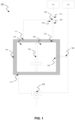
- FIG 1 shows schematically a sanitary water storage device 100 according to a preferred embodiment, configured to store and supply sanitary hot water.
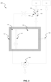
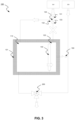
- Figures 2 and 3 show an operating principle of the embodiment shown in figure 1 .
- Sanitary hot water is typically used for personal care but also for other cleaning actions, such as washing up crockery, cutlery or cookware, or general cleaning tasks.
- the hot water typically comes from a hot water source such as a boiler, central heating boiler or a combination thereof.
- the boiler heats cold water to a predetermined temperature, typically about 60 to 65°C.
- the sanitary water storage device 100 can thus for instance be used in combination with the mixer tap of a bath, bidet, shower or sink.
- the water storage device 100 can further for instance also be used between a hot water collector and the user in order to shorten the time spent waiting for hot water. It will further be apparent that these examples are not intended to be limitative and that other sanitary installations, also referred to here as sanitary systems or external consumers, which use sanitary hot water can also be used in combination with the sanitary water storage device 100.
- hot water is fed to the sanitary water storage device 100 with a hot water feed conduit 310.
- the sanitary water storage device 100 can also be connected to a cold water feed conduit, which is designated with reference numeral 320.
- the sanitary water storage device 100 also shortened to storage device 100, comprises a housing 101.
- the housing 101 has a first reservoir 110 and a second reservoir 120, wherein a volume of the first reservoir 110 and a volume of the second reservoir 120 are modifiable proportionally to each other.
- first reservoir 110 and second reservoir 120 has a volume, also referred to respectively as first volume for first reservoir 110 and second volume for second reservoir 120, which is modifiable.
- first volume for first reservoir 110 and second reservoir 120 is variable and may therefore increase in volume, as well as decrease in volume.
- the volume of first reservoir 110 can thus for instance increase from an initial volume of 10l to a volume of 20l, as shown in figure 3 .
- the volume of first reservoir 110 can further for instance also decrease from an initial volume of 10l to a volume of 1l, as shown in figure 2 . It is noted here that the volume of first reservoir 110 is modifiable proportionally to second reservoir 120, and vice versa. This means that when the volume of first reservoir 110 increases, the volume of second reservoir 120 decreases correspondingly, and vice versa. When the volume of second reservoir 120 increases, the volume of first reservoir 110 will decrease correspondingly, and vice versa.
- Such reservoirs can be given different forms, for instance the form of a balloon; a form using a movable partition between first reservoir 110 and second reservoir 120, as will be elucidated below; or a form with a flexible membrane between first reservoir 110 and second reservoir 120.
- the volume of first reservoir 110 and second reservoir 120 together is preferably at least 3 litres, preferably at least 5 litres. Tests have shown that, from the boiler to a consumer located furthest from the boiler, hot water needs about 1 minute to reach the user in the average household. By providing a volume of at least 8 litres, sufficient hot water is present in water storage device 100, even in the case of consumers with a high flow rate, such as a rain shower. Only a limited quantity of hot water is thus needed to obtain a hot water temperature which is pleasant for the body, for instance when showering, since the hot water is still being mixed with cold water.
- Storage device 100 further comprises a water distributing means 130 with an inlet 131, a first outlet 132 and a second outlet 133.
- the inlet 131 is configured to be connectable to a hot water feed conduit 310.
- Inlet 131 can for this purpose be provided with for instance a flange connection, screw thread connection or press fit which allows the storage device 100 to be connected to the hot water feed conduit in simple manner. It is noted here that a welded connection is not precluded either.
- Figure 1 further shows that first outlet 132 is in liquid connection with first reservoir 110, for instance by means of a conduit extending from first outlet 132 to first reservoir 110.
- the first reservoir 110 can for this purpose be provided with a first reservoir inlet 111.
- the second outlet 132 is in liquid connection with the second reservoir 120, for instance by means of a conduit extending from second outlet 133 to second reservoir 120.
- the second reservoir 120 can for this purpose be provided with a second reservoir inlet 121.
- the water distributing means 130 is configured to bring inlet 131 into liquid connection with first outlet 132 or second outlet 133, depending on a liquid temperature measured at the inlet.
- the water distributing means 130 brings inlet 131 into liquid connection with first reservoir 110, such that first reservoir 110 is filled.
- a predetermined threshold value for instance 45°C
- the water distributing means 130 brings inlet 131 into liquid connection with first reservoir 110, such that first reservoir 110 is filled.
- a thermostatic control valve which determines the flow direction on the basis of a bimetal or using an electronic sensor. Inside the volume of the housing this results in an increase of the volume of first reservoir 110 and a proportional decrease of the volume of second reservoir 120. This situation is shown in figure 3 .
- the water distributing means brings inlet 131 into liquid connection with the second reservoir. Inside the volume of the housing this results in an increase of the volume of second reservoir 120 and in a proportional decrease of the volume of first reservoir 110.
- the operating principle of storage device 100 is elucidated as follows, in the context of the example of a person showering.
- the hot water will be fed to first reservoir 110 and fill first reservoir 110.
- the volume of first reservoir 110 increases and first reservoir 110 simultaneously stores hot water. This is referred to as a filling stage of the first reservoir 110.
- the volume of second reservoir 120 decreases correspondingly during the filling stage. Within the boundary of the housing this is realized by a pressure exerted by the hot water flowing into first reservoir 110 on second reservoir 120.
- a portion of the hot water can also be used by the user.
- the hot water remains stored in first reservoir 110.
- the cycle of feeding water from the heating boiler starts over with a subsequent shower, for instance the next day.
- the water in the hot water conduit will then typically have cooled down.
- the water distributing means 130 will hereby bring the cold water of inlet 131 into connection with second reservoir 120.
- Second reservoir 120 will initially be filled with cold water and increase in volume, as shown in figure 2 . Inside the volume of the housing first reservoir 110 decreases correspondingly to the increase of second reservoir 120.
- Figure 1 shows that the water storage device 100 can comprise a partition 140 which is provided movably between first reservoir 110 and second reservoir 120.
- the housing 101 can for instance define one volume, which volume separates into a first reservoir 110 and a second reservoir 120 by means of partition 140. Because partition 140 is movable, a modification of the volume of first reservoir 110 also results in a proportional modification of the volume of second reservoir 120.
- Such a setup is robust because it has a limited number of moving parts and can moreover be produced in relatively simple manner.
- the partition 140 can comprise a seal which seals first reservoir 110 substantially watertightly relative to second reservoir 120. In this way the water storage device 100 can store the hot water in improved manner.
- the partition can comprise an insulating material for insulating first reservoir 110 and second reservoir 120 from each other in further improved manner, whereby the hot water is further stored in improved manner.
- housing 101 preferably comprises an insulating material. It is important on one hand for water storage device 100 to be insulated in order to preserve the thermal energy of the hot water in first reservoir 110. It is on the other hand not essential for the housing to comprise insulating material. Insulating material can thus also be provided outside the housing 110, glass wool or insulating foam arranged all around the housing can for instance insulate the housing and/or the first reservoir from the external environment in relatively simple manner, which embodiment is however not shown. When housing 101 comprises insulating material, the water storage device 100 will be able to insulate first reservoir 110 and second reservoir 120 from the external environment in improved manner.
- the insulating material preferably has a lambda value below 0.02 W/mK, more preferably below 0.015 W/mK, still more preferably below 0.01 W/mK. Tests have shown that hot water that is stored inside housing 101 with said lambda value will only decrease in temperature within a determined range, for instance about 5° per 24 hours.
- a boiler typically heats water to about 60°C, a user requiring hot water typically does not require such a high temperature.
- a user can thus for instance already comfortably shower or bathe in water of about 40°C.
- the selected insulating material is preferably a type of material which only allows a maximum temperature drop of 20°C over a time period of 72 hours.
- housing 101 can be formed from a double-walled housing wall which is formed by two wall parts. An at least partial vacuum prevails between the two wall parts, which functions as thermal insulation similar to a double-walled insulating container.
- Such a preferred embodiment limits the number of cold bridges considerably, whereby first reservoir 110 and second reservoir 120 are insulated from the surrounding area in further improved manner.
- first reservoir 110 has a first reservoir outlet 112 which is connectable to an external consumer, such as a mixer tap 200.
- an external consumer such as a mixer tap 200.
- Second reservoir 120 can also have a second reservoir outlet 122 which is connectable to the external consumer 200, preferably by means of the cold water feed conduit 320 of the external consumer.
- the water storage device 100 it is preferred here for the water storage device 100 to further comprise a non-return valve 150 provided between the second reservoir outlet 122 and the external consumer, wherein the non-return valve allows a liquid flow in only one direction away from the second reservoir. In this way the water storage device 100 can further be connected to a cold water feed conduit 320 without the cold water being able to flow directly into the second reservoir 120.
- Figure 4 shows a schematic representation of a sanitary system with a water storage device 100 according to a further preferred embodiment.
- the water storage device 100 further comprises the cold water inlet 160 in this preferred embodiment.
- the cold water inlet 160 is illustrated in figure 4 as a flange connection, but can also be a screw thread connection or welded connection.
- the water storage device 100 preferably further comprises here a priority valve 161 between the non-return valve 150 and the cold water inlet 160.
- the priority valve 161 is configured to give priority to a liquid flow coming from the second reservoir 120 over a liquid flow coming from the cold water inlet 160. A hydrodynamic equilibrium of the water storage device, and consequently the sanitary system, is preserved in this way. The water can thus flow from second reservoir 120 to the user without cold water coming from the cold water inlet 160 having a direct influence thereon.
- priority valve 161 can prioritize the liquid flow coming from the cold water inlet 160 and allow a liquid flow therefrom to the user.
- a priority valve can for instance be an overflow valve which determines on the basis of a liquid pressure on the user side which liquid flow has priority.
- an overflow valve can prioritize a liquid flow from the cold water inlet 160.
- the water storage device 100 can comprise a heating element 170 which is configured to heat the water in first reservoir 110 at least partially. This allows the water in the first reservoir to be stored at relatively high temperature, for instance when there is a considerable period of time between periods of use of the sanitary system. When water storage device 100 is used daily, such a heating element 170 is however not needed.
- At least one of first reservoir 110 and second reservoir 120 is preferably in liquid connection with a legionella flushing device 180. The advantage hereof is based on the insight that growth of legionella can be prevented in warm, typically still water. By providing a legionella flushing device 180 both the first reservoir and the second reservoir can be purged in order to clean the first reservoir and/or the second reservoir.
Landscapes
- Health & Medical Sciences (AREA)
- Life Sciences & Earth Sciences (AREA)
- Engineering & Computer Science (AREA)
- Hydrology & Water Resources (AREA)
- Public Health (AREA)
- Water Supply & Treatment (AREA)
- Domestic Plumbing Installations (AREA)
- Devices For Dispensing Beverages (AREA)
Applications Claiming Priority (1)
| Application Number | Priority Date | Filing Date | Title |
|---|---|---|---|
| BE20225798A BE1030941B1 (nl) | 2022-10-05 | 2022-10-05 | Sanitair systeem voor instant warm water |
Publications (1)
| Publication Number | Publication Date |
|---|---|
| EP4350089A1 true EP4350089A1 (de) | 2024-04-10 |
Family
ID=84329480
Family Applications (1)
| Application Number | Title | Priority Date | Filing Date |
|---|---|---|---|
| EP23200274.1A Pending EP4350089A1 (de) | 2022-10-05 | 2023-09-28 | Sanitärsystem für sofortige abgabe von heisswasser |
Country Status (3)
| Country | Link |
|---|---|
| US (1) | US12416137B2 (de) |
| EP (1) | EP4350089A1 (de) |
| BE (1) | BE1030941B1 (de) |
Citations (3)
| Publication number | Priority date | Publication date | Assignee | Title |
|---|---|---|---|---|
| AT500552B1 (de) * | 2004-02-11 | 2009-08-15 | Duennleder Werner | Trinkwasser-anlage |
| WO2012001683A2 (en) * | 2010-06-28 | 2012-01-05 | Or-Ad Ltd. | System for saving the initial water consumption while taking a shower |
| EP2706154A1 (de) * | 2012-09-07 | 2014-03-12 | Nadace Czech Technical University Media | Mischvorrichtung, insbesondere für Duschen |
Family Cites Families (3)
| Publication number | Priority date | Publication date | Assignee | Title |
|---|---|---|---|---|
| CA2709945A1 (en) * | 2007-12-20 | 2009-07-02 | Andre Boulay | Multi-chamber water heater |
| GB2605588B (en) * | 2021-04-02 | 2023-07-26 | William Yemm Richard | Thermal energy storage |
| WO2023107549A1 (en) * | 2021-12-09 | 2023-06-15 | A. O. Smith Corporation | Tank water heater and water heating system |
-
2022
- 2022-10-05 BE BE20225798A patent/BE1030941B1/nl active IP Right Grant
-
2023
- 2023-09-28 EP EP23200274.1A patent/EP4350089A1/de active Pending
- 2023-10-04 US US18/480,629 patent/US12416137B2/en active Active
Patent Citations (3)
| Publication number | Priority date | Publication date | Assignee | Title |
|---|---|---|---|---|
| AT500552B1 (de) * | 2004-02-11 | 2009-08-15 | Duennleder Werner | Trinkwasser-anlage |
| WO2012001683A2 (en) * | 2010-06-28 | 2012-01-05 | Or-Ad Ltd. | System for saving the initial water consumption while taking a shower |
| EP2706154A1 (de) * | 2012-09-07 | 2014-03-12 | Nadace Czech Technical University Media | Mischvorrichtung, insbesondere für Duschen |
Also Published As
| Publication number | Publication date |
|---|---|
| BE1030941B1 (nl) | 2024-05-07 |
| US12416137B2 (en) | 2025-09-16 |
| US20240117611A1 (en) | 2024-04-11 |
| BE1030941A1 (nl) | 2024-04-29 |
Similar Documents
| Publication | Publication Date | Title |
|---|---|---|
| US6098213A (en) | Water temperature regulator | |
| US4924536A (en) | System of conserving water in a building | |
| GB2052698A (en) | Domestic Hot Water Supply | |
| US20100319790A1 (en) | Usable water usage device | |
| WO2018169394A1 (en) | Shower system | |
| JP2011518969A (ja) | 貯水機能を有する混合システム及びその使用 | |
| CA2252350A1 (en) | Water saving apparatus | |
| CN203852265U (zh) | 一种节水型淋浴装置 | |
| EP4350089A1 (de) | Sanitärsystem für sofortige abgabe von heisswasser | |
| WO2020066110A1 (ja) | 給湯システム | |
| US10968611B2 (en) | Water diversion assembly | |
| JP6603051B2 (ja) | 給水給湯システム | |
| CN101280933A (zh) | 不同种类热水器的联合使用方法 | |
| WO2012080722A2 (en) | Apparatus for hot water storage | |
| CN201606961U (zh) | 一种淋浴节水循环系统 | |
| CN105672406B (zh) | 一种冷热水供水装置以及冷热水供水系统 | |
| WO2013150536A2 (en) | A hot water system | |
| RU2123155C1 (ru) | Система отопления с естественной циркуляцией телпоносителя и горячим водоснабжением | |
| WO2020093248A1 (zh) | 一种光控分体式非承压太阳能热水装置 | |
| JP2019117005A (ja) | 給湯暖房システム | |
| JP2005134028A (ja) | 貯湯式温水器 | |
| CN205577019U (zh) | 一种冷热水供水装置以及冷热水供水系统 | |
| EP4636176A2 (de) | System zum auffangen von wasser in wartestellung | |
| CN109579328B (zh) | 热水贮存槽和供热水系统 | |
| CN102469635A (zh) | 家电产品用瞬间加热加热器组件 |
Legal Events
| Date | Code | Title | Description |
|---|---|---|---|
| PUAI | Public reference made under article 153(3) epc to a published international application that has entered the european phase |
Free format text: ORIGINAL CODE: 0009012 |
|
| STAA | Information on the status of an ep patent application or granted ep patent |
Free format text: STATUS: THE APPLICATION HAS BEEN PUBLISHED |
|
| AK | Designated contracting states |
Kind code of ref document: A1 Designated state(s): AL AT BE BG CH CY CZ DE DK EE ES FI FR GB GR HR HU IE IS IT LI LT LU LV MC ME MK MT NL NO PL PT RO RS SE SI SK SM TR |
|
| STAA | Information on the status of an ep patent application or granted ep patent |
Free format text: STATUS: REQUEST FOR EXAMINATION WAS MADE |
|
| 17P | Request for examination filed |
Effective date: 20241009 |
|
| RBV | Designated contracting states (corrected) |
Designated state(s): AL AT BE BG CH CY CZ DE DK EE ES FI FR GB GR HR HU IE IS IT LI LT LU LV MC ME MK MT NL NO PL PT RO RS SE SI SK SM TR |