EP4349286A1 - Obturator and trocar - Google Patents
Obturator and trocar Download PDFInfo
- Publication number
- EP4349286A1 EP4349286A1 EP22815720.2A EP22815720A EP4349286A1 EP 4349286 A1 EP4349286 A1 EP 4349286A1 EP 22815720 A EP22815720 A EP 22815720A EP 4349286 A1 EP4349286 A1 EP 4349286A1
- Authority
- EP
- European Patent Office
- Prior art keywords
- grip
- shaft
- cannula
- obturator
- shape
- Prior art date
- Legal status (The legal status is an assumption and is not a legal conclusion. Google has not performed a legal analysis and makes no representation as to the accuracy of the status listed.)
- Pending
Links
- 238000003780 insertion Methods 0.000 claims description 10
- 230000037431 insertion Effects 0.000 claims description 10
- 230000007423 decrease Effects 0.000 claims description 4
- 238000000926 separation method Methods 0.000 claims description 4
- 210000003811 finger Anatomy 0.000 description 24
- 238000005516 engineering process Methods 0.000 description 15
- 210000003813 thumb Anatomy 0.000 description 10
- 238000000034 method Methods 0.000 description 9
- 230000000694 effects Effects 0.000 description 4
- 238000001356 surgical procedure Methods 0.000 description 3
- CURLTUGMZLYLDI-UHFFFAOYSA-N Carbon dioxide Chemical compound O=C=O CURLTUGMZLYLDI-UHFFFAOYSA-N 0.000 description 2
- 229920000122 acrylonitrile butadiene styrene Polymers 0.000 description 2
- 230000004048 modification Effects 0.000 description 2
- 238000012986 modification Methods 0.000 description 2
- 238000007790 scraping Methods 0.000 description 2
- 229910001069 Ti alloy Inorganic materials 0.000 description 1
- 210000000683 abdominal cavity Anatomy 0.000 description 1
- 210000003815 abdominal wall Anatomy 0.000 description 1
- 239000004676 acrylonitrile butadiene styrene Substances 0.000 description 1
- 229910002092 carbon dioxide Inorganic materials 0.000 description 1
- 239000001569 carbon dioxide Substances 0.000 description 1
- 230000003749 cleanliness Effects 0.000 description 1
- 239000000428 dust Substances 0.000 description 1
- 230000006872 improvement Effects 0.000 description 1
- 239000007788 liquid Substances 0.000 description 1
- 210000004932 little finger Anatomy 0.000 description 1
- 239000000463 material Substances 0.000 description 1
- 230000007246 mechanism Effects 0.000 description 1
- 229910052751 metal Inorganic materials 0.000 description 1
- 239000002184 metal Substances 0.000 description 1
- 235000011962 puddings Nutrition 0.000 description 1
- 239000011347 resin Substances 0.000 description 1
- 229920005989 resin Polymers 0.000 description 1
- 239000010935 stainless steel Substances 0.000 description 1
- 229910001220 stainless steel Inorganic materials 0.000 description 1
Images


Classifications
-
- A—HUMAN NECESSITIES
- A61—MEDICAL OR VETERINARY SCIENCE; HYGIENE
- A61B—DIAGNOSIS; SURGERY; IDENTIFICATION
- A61B17/00—Surgical instruments, devices or methods, e.g. tourniquets
- A61B17/34—Trocars; Puncturing needles
- A61B17/3417—Details of tips or shafts, e.g. grooves, expandable, bendable; Multiple coaxial sliding cannulas, e.g. for dilating
- A61B17/3421—Cannulas
-
- A—HUMAN NECESSITIES
- A61—MEDICAL OR VETERINARY SCIENCE; HYGIENE
- A61B—DIAGNOSIS; SURGERY; IDENTIFICATION
- A61B17/00—Surgical instruments, devices or methods, e.g. tourniquets
- A61B17/34—Trocars; Puncturing needles
Definitions
- the present disclosed technology relates to an obturator and a trocar.
- a trocar In surgery, a trocar is used.
- the trocar is composed of a cannula and an obturator.
- the cannula has a tubular shape with an insertion hole through which an endoscope and/or a treatment tool is guided into a body cavity.
- the obturator includes a shaft that is inserted into the insertion hole of the cannula and of which a distal end is sharp-pointed in a needle-like shape to be stuck into a body wall of a patient and a grip to which a proximal end of the shaft is attached and that is gripped by an operator. The operator separates the obturator from the cannula after sticking the shaft of the obturator into the body wall together with the cannula and then leaves the cannula alone in the body wall.
- JP2003-047618A Described in JP2003-047618A is an obturator in which one recessed portion is formed at one surface of a quadrangular frustum-shaped grip.
- An embodiment according to the present disclosed technology provides an obturator and a trocar improved in operation stability.
- An obturator includes a shaft that is inserted into a cannula and of which a distal end is sharp-pointed in a needle-like shape to be stuck into a body wall, a grip to which a proximal end of the shaft is attached and that is gripped by an operator, and at least two recessed portions that are formed at the grip and on which fingers of the operator are hooked.
- the two recessed portions are formed at opposite positions on the grip.
- the recessed portion includes at least a first surface that is formed along an axial direction of the shaft and a second surface that is connected to the first surface on a connection end side and that intersects the first surface, the connection end being one end of the grip to which the proximal end of the shaft is attached.
- first surface and the second surface are connected to each other by a curved surface.
- At least one of the first surface or the second surface includes a curved surface.
- the first surface extends from a position near the connection end to an open end, which is the other end of the grip and is on a side opposite to the connection end.
- the grip has a tapered shape of which a thickness decreases toward an open end from a connection end, the connection end being one end of the grip to which the proximal end of the shaft is attached and the open end being the other end of the grip that is on a side opposite to the connection end.
- the grip has a shape that is obtained in a case where a portion of a prolate spheroid is cut along a short axial direction or has a truncated conical shape.
- the grip has a columnar shape.
- a length of the grip in an axial direction of the shaft is 1.2 times or more and less than 1.5 times a length of the grip in a radial direction of the shaft.
- a length of the grip in an axial direction of the shaft is 40 mm or greater and smaller than 70 mm.
- the grip includes a notched portion in which at least a portion of a button for separation of the cannula is accommodated and that is disposed at a position different from a position of the recessed portion in a circumferential direction of the shaft.
- the grip includes a protrusion that is connected to the cannula and that is provided at a position corresponding to the recessed portion in a circumferential direction of the shaft.
- a trocar according to an aspect of the present disclosure includes any obturator described above and a cannula into which the obturator is attachably and detachably inserted.
- the cannula includes a cannula body that has a tubular shape with an insertion hole into which the shaft is inserted and a connecting portion to which a proximal end of the cannula body is attached, to which the grip is attachably and detachably connected, and of which a length in an axial direction of the shaft is shorter than a length of the grip in the axial direction.
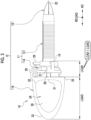
- a trocar 10 is composed of a cannula 11 and an obturator 12.
- the cannula 11 includes a cannula body 13 and a connecting portion 14.
- the obturator 12 includes a shaft 15 and a grip 16. Note that Fig. 1 shows a state where the cannula 11 is mounted on the obturator 12 and Fig. 2 shows a state where the cannula 11 is separated from the obturator 12.
- the cannula body 13 has a tubular shape with an insertion hole 17 into which the shaft 15 is inserted.
- the connecting portion 14 also has a tubular shape with an insertion hole 18 that leads to the insertion hole 17.
- the insertion holes 17 and 18 have substantially the same diameter as each other.
- the connecting portion 14 has a diameter slightly larger than the diameter of the cannula body 13 and is attached to a proximal end 19 of the cannula body 13.
- the grip 16 is attachably and detachably connected to the connecting portion 14.
- the connecting portion 14 is provided with a button 20.
- the button 20 is operated by an operator in a case where the cannula 11 is to be separated from the obturator 12.
- two grooves 21 are formed along an axial direction AD of the shaft 15.
- the two grooves 21 are disposed at positions 180° separated from each other, that is, at positions facing each other in a plan view of the connecting portion 14 as seen in the axial direction AD of the shaft 15.
- the connecting portion 14 is provided with a port 29 through which a gas such as carbon dioxide is introduced into a body cavity.
- the connecting portion 14 includes a latching mechanism for attachably and detachably holding the grip 16, a seal for preventing a gas and liquid in a body cavity from leaking to the outside, and the like.
- a body cavity is, for example, an abdominal cavity.
- the shaft 15 has an elongated rod-like shape with a distal end 22 and a proximal end 23 and is made of, for example, metal, such as a titanium alloy.
- the distal end 22 is sharp-pointed in a needle-like shape to be stuck into a body wall BW (refer to Figs. 5 and 6 ) of a patient.
- the length of the shaft 15 in the axial direction AD is larger than the length of the cannula body 13 in the axial direction AD. Therefore, in a state where the cannula 11 is mounted on the obturator 12, the distal end 22 of the shaft 15 protrudes from the cannula body 13 as shown in Fig. 1 .
- the shaft 15 may be made of a resin, such as an acrylonitrile-butadiene-styrene (ABS) resin.
- ABS acrylonitrile-butadiene-styrene
- the distal end 22 may be made of an ABS resin and a portion other than the distal end 22 may be made of a different material, such as stainless steel, for example.
- the grip 16 is attached to the proximal end 23 of the shaft 15. A corner of the grip 16 is rounded through R chamfering. The grip 16 is to be gripped by the operator (refer to Figs. 5 and 6 ). Two recessed portions 24 are formed at the grip 16. Each of the two recessed portions 24 is formed over an area from a position near a connection end 25, which is one end of the grip 16 and to which the proximal end 23 of the shaft 15 is attached, to a position near an open end 26, which is the other end of the grip 16 and is on a side opposite to the connection end 25.
- the two recessed portions 24 are disposed at positions 180° separated from each other, that is, at positions facing each other in a plan view of the grip 16 as seen in the axial direction AD of the shaft 15. Fingers of the operator are to be hooked on the recessed portions 24 (refer to Figs. 5 and 6 ). Therefore, the recessed portions 24 can also be referred to as finger hooking portions. Note that the operator refers to all persons who operate the trocar 10, such as a doctor who performs surgery using the trocar 10.
- the connection end 25 is provided with a notched portion 27. Approximately half of the button 20 is accommodated in the notched portion 27.
- the notched portion 27 is disposed at a position different from the positions of the recessed portions 24 in a circumferential direction CD of the shaft 15. Specifically, the notched portion 27 is disposed at an intermediate position between the two recessed portions 24. In other words, in a plan view of the grip 16 as seen in the axial direction AD of the shaft 15, the notched portion 27 is disposed at a position 90° separated from each of the two recessed portions 24 which are disposed at the positions 180° separated from each other.
- connection end 25 is provided with two protrusions 28 (refer to Fig. 4 as well).
- the two protrusions 28 are disposed at positions 180° separated from each other, that is, at positions facing each other in a plan view of the grip 16 as seen in the axial direction AD of the shaft 15. That is, the two protrusions 28 are provided at positions corresponding to the recessed portions 24 in the circumferential direction CD of the shaft 15.
- the positions of the cannula 11 and the obturator 12 in the circumferential direction CD are adjusted such that the protrusions 28 are fitted into the grooves 21. That is, the grooves 21 and the protrusions 28 have a role of positioning the cannula 11 in the circumferential direction CD while the cannula 11 is being mounted on the obturator 12.
- each of the recessed portions 24 includes a first surface 30 and a second surface 31.
- the first surface 30 is formed along the axial direction AD.
- the first surface 30 is a surface approximately parallel to the axial direction AD.
- the second surface 31 is formed along a radial direction RD of the shaft 15.
- the second surface 31 is a surface approximately parallel to the radial direction RD. That is, the first surface 30 and the second surface 31 intersect each other.
- the second surface 31 is connected to the first surface 30 via a connection surface 32 on the connection end 25 side.
- connection surface 32 is a curved surface that smoothly connects the first surface 30 and the second surface 31 to each other, and is an example of a "curved surface" according to the present disclosed technology.
- radial direction RD refers to a direction orthogonal to the first surface 30.
- the grip 16 has a tapered shape of which the thickness decreases toward the open end 26 from the connection end 25. More specifically, as shown in Fig. 4 , the grip 16 has a shape that is obtained in a case where a portion (here, approximately half) of a prolate spheroid PS virtually represented by a two-dot chain line is cut along a short axial direction SAD which is the same direction as the radial direction RD. In the following description, a portion of the grip 16 that is on the open end 26 side, that is approximately half of the grip 16, and that includes a tapered curved surface will be referred to as a tapered portion 33. Note that the prolate spheroid PS is a three-dimensional shape obtained in a case where an ellipse is rotated with the major axis as the rotation axis and a rugby ball is a representative example thereof.
- each of the recessed portions 24 is formed by cutting or scraping off a portion of the grip 16 having a shape that is obtained in a case where approximately half of the prolate spheroid PS is cut along the short axial direction SAD. Therefore, the recessed portions 24 can also be referred to as cutting portions or scraped portions.
- the recessed portions 24 are level differences formed by cutting or scraping off a portion of the grip 16. Therefore, the recessed portions 24 can also be referred to as level difference portions.
- a length LCAD of the connecting portion 14 in the axial direction AD is shorter than a length LGAD of the grip 16 in the axial direction AD (LCAD ⁇ LGAD).
- the length LGAD of the grip 16 in the axial direction AD is 1.2 times or more and less than 1.5 times a length LGRD of the grip 16 in the radial direction RD (1.2 LGRD ⁇ LGAD ⁇ 1.5 LGRD).
- the length LGAD of the grip 16 in the axial direction AD is 40 mm or greater and smaller than 70 mm (40 mm ⁇ LGAD ⁇ 70 mm).
- the length LGAD of the grip 16 in the axial direction AD is 57 mm
- the length LGRD of the grip 16 in the radial direction RD is 42 mm.
- LGAD ⁇ 1.36 LGRD a condition that 1.2 LGRD ⁇ LGAD ⁇ 1.5 LGRD is satisfied.
- 40 mm ⁇ LGAD ⁇ 70 mm is also satisfied.
- Fig. 5 shows a case where a thumb is hooked on one recessed portion 24 and a finger other than the thumb is hooked on the other recessed portion 24. More specifically, the tip of the thumb is brought into contact with the second surface 31 of the one recessed portion 24 and the pad of the thumb is brought into contact with the first surface 30 and the connection surface 32 of the one recessed portion 24.
- the tip of at least one of fingers other than the thumb (for example, a middle finger) is brought into contact with the second surface 31 of the other recessed portion 24 and the pad of the finger other than the thumb is brought into contact with the first surface 30 and the connection surface 32 of the other recessed portion 24.
- Fig. 5 shows a state immediately before the shaft 15 is stuck into the body wall BW together with the cannula 11.
- the operator causes the trocar 10 to access the body wall BW by bringing the trocar 10 down in an approximately perpendicular direction and, in some cases, the operator sticks the shaft 15 into the body wall BW up to a position where the connecting portion 14 reaches a surface of the body wall BW while rotating the trocar 10 in the circumferential direction CD.
- a portion of the body wall BW into which the shaft 15 is stuck may be incised in advance with a scalpel.
- the body wall BW is, for example, an abdominal wall.
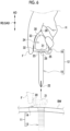
- Fig. 6 shows a state where the cannula 11 is left alone at the body wall BW after the shaft 15 is stuck into the body wall BW up to a position where the connecting portion 14 reaches the surface of the body wall BW and then the obturator 12 is separated from the cannula 11.
- the operator switches from a gripping method as shown in Fig. 5 to a gripping method of wrapping the grip 16 (particularly, the tapered portion 33) with a palm of a hand as shown in the drawing.
- the operator puts a thumb at a position between the two recessed portions 24 at which the button 20 is disposed, wraps an index finger, a middle finger, and a ring finger around the other recessed portion 24 side, and folds the index finger, the middle finger, and the ring finger. Furthermore, a little finger is folded along with the ring finger.
- the operator operates the button 20 with the tip of the thumb as represented by a broken line to disconnect the connecting portion 14 and the grip 16 from each other, that is, to disconnect the cannula 11 and the obturator 12 from each other.
- the operator separates the obturator 12 from the cannula 11 by pulling the obturator 12 in a direction opposite to a direction in which the shaft 15 is stuck into the body wall BW and leaves the cannula 11 alone at the body wall BW.
- the tapered portion 33 can be referred to as a palm-wrapped portion as well.
- the tapered portion 33 can be referred to as a curved surface portion as well.
- Fig. 7 is a flowchart showing an example of the procedure for operating the trocar 10.
- the operator mounts the cannula 11 on the obturator 12 (Step ST100).
- the operator adjusts the positions of the cannula 11 and the obturator 12 in the circumferential direction CD such that the protrusions 28 are fitted into the grooves 21 and the button 20 is accommodated in the notched portion 27.
- Step ST110 the operator hooks fingers F on the recessed portions 24 of the grip 16 and sticks the shaft 15 into the body wall BW together with the cannula 11 while gripping the grip 16 (Step ST110).
- Step ST120 After the shaft 15 is stuck into the body wall BW up to a position where the connecting portion 14 reaches the surface of the body wall BW, the operator operates the button 20 as shown in Fig. 6 so that the obturator 12 is separated from the cannula 11 and the cannula 11 is left alone at the body wall BW (Step ST120). Thereafter, the operator performs, for example, introduction of an endoscope and/or a treatment tool into the insertion holes 17 and 18 of the cannula 11 and performs surgery on the patient.
- the obturator 12 includes the shaft 15, the grip 16, and the recessed portions 24.
- the shaft 15 is inserted into the cannula 11, and the distal end 22 thereof is sharp-pointed in a needle-like shape to be stuck into the body wall BW.
- the proximal end 23 of the shaft 15 is attached to the grip 16 and the grip 16 is gripped by the operator.
- Two recessed portions 24 are formed at the grip 16, and the fingers F of the operator are hooked on the recessed portions 24. Therefore, the obturator 12 can be further improved in terms of operation stability in comparison with an obturator disclosed in JP2003-047618A in which only one recessed portion is formed at one surface of a grip.
- the two recessed portions 24 are formed at opposite positions on the grip 16. Therefore, the grip 16 can be formed in a simple and symmetrical shape.
- each of the recessed portion 24 includes the first surface 30 that is formed along the axial direction AD of the shaft 15 and the second surface 31 that is connected to the first surface 30 on the connection end 25 side, the connection end 25 being one end of the grip to which the proximal end 23 of the shaft 15 is attached.
- the second surface 31 intersects the first surface 30.
- the first surface 30 and the second surface 31 are connected to each other by the connection surface 32 which is a curved surface. Therefore, it is possible to smoothly apply, with one finger, a force to the first surface 30 that rotates the shaft 15 in the circumferential direction CD and a force to the second surface 31 that pushes the shaft 15 in a direction in which the shaft 15 is stuck in comparison with a case where the first surface 30 and the second surface 31 are connected to each other at an angle. In addition, it is possible to prevent dust from accumulating in a connection portion between the first surface 30 and the second surface 31 in comparison with a case where the first surface 30 and the second surface 31 are connected at an angle.
- connection portion between the first surface 30 and the second surface 31 it is possible to easily clean the connection portion between the first surface 30 and the second surface 31 in comparison with a case where the first surface 30 and the second surface 31 are connected at an angle. Therefore, it is possible to maintain the cleanliness of the connection portion between the first surface 30 and the second surface 31.
- the grip 16 has a tapered shape (the tapered portion 33) of which the thickness decreases toward the open end 26 from the connection end 25. Since this shape is a shape that conforms to a gripping shape of the hand H, it is easy to grip the grip 16 with the hand H. Particularly, in the case of a gripping method in which the tapered portion 33 is wrapped with a palm as shown in Fig. 6 , it is possible to fully exhibit an effect of being easily gripped by the hand H.
- the grip 16 has a shape obtained in a case where a portion of the prolate spheroid PS is cut along the short axial direction SAD.
- the open end 26 of the grip 16 has a rounded shape (the tapered portion 33) and thus there is no burden imposed on the palm of the hand H even in a case where the palm comes into contact with the open end 26.
- the length LGAD of the grip 16 in the axial direction AD is 1.2 times or more and less than 1.5 times the length LGRD of the grip 16 in the radial direction RD.
- the length LGAD is 1.2 times or more and less than 1.5 times the length LGRD, it is easy to grip the grip 16 with the hand H and to operate the obturator 12 (the trocar 10).
- the length LGAD is less than 1.2 times or 1.5 times or more the length LGRD, it is difficult to grip the grip 16 with the hand H and to operate the obturator 12 (trocar 10).
- the length LGAD of the grip 16 in the axial direction AD is 40 mm or greater and smaller than 70 mm.
- the length LGAD is 40 mm or greater and less than 70 mm, it is easy to grip the grip 16 with the hand H and to operate the obturator 12 (trocar 10).
- the length LGAD is less than 40 mm or 70 mm or more, it is difficult to grip the grip 16 with the hand H and to operate the obturator 12 (trocar 10).
- the grip 16 includes the notched portion 27 in which at least a portion of the button 20 for separation of the cannula 11 is accommodated and that is disposed at a position different from the positions of the recessed portions 24 in the circumferential direction CD. Therefore, the recessed portions 24 and the notched portion 27 do not interfere with each other and thus it is possible to reduce a probability that the button 20 is erroneously operated by the fingers F hooked on the recessed portions 24.
- the grip 16 includes the protrusions 28 that are connected to the cannula 11 and that are provided at positions corresponding to the recessed portions 24 in the circumferential direction CD. Therefore, the protrusions 28 can be easily visually recognized in a case where the cannula 11 is to be mounted on the obturator 12, and it is possible to easily adjust the positions of the cannula 11 and the obturator 12 in the circumferential direction CD such that the protrusions 28 are fitted into the grooves 21.
- the cannula 11 includes the cannula body 13 that has a tubular shape with the insertion hole 17 into which the shaft 15 is inserted and the connecting portion 14 to which the proximal end 19 of the cannula body 13 is attached and to which the grip 16 is attachably and detachably connected.
- the length LCAD of the connecting portion 14 in the axial direction is shorter than the length LGAD of the grip 16 in the axial direction AD. Therefore, it is possible to operate the trocar 10 with the grip 16 having a size relatively larger than the size of the connecting portion 14 and to improve the operation stability in comparison with the case of the grip 16 having a size relatively smaller than the size of the connecting portion 14.
- the button 20 for separation of the cannula 11 from the obturator 12 may be provided at the grip 16 instead of the connecting portion 14.
- the notched portion 27 may not be provided.
- a recessed portion 51 of a grip 50 shown in Fig. 8 includes a first surface 52 composed of a curved surface protruding inward.
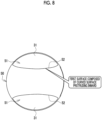
- a recessed portion 56 of a grip 55 shown in Fig. 9 includes a first surface 57 composed of a curved surface protruding outward.
- the feeling of fitting of the finger F can be enhanced since the shape of the first surface 52 coincides with the shape of the pad of the finger F.
- the first surface 57 has a shape that further conforms to the gripping shape of the hand H, it is easier to grip the first surface 57 with the hand H.
- recessed portions 51 and 56 of which the first surfaces 52 and 57 are composed of curved surfaces are shown.
- the present disclosed technology is not limited thereto.
- a second surface 62 composed of a curved surface protruding toward the connection end 25 may also be provided.
- the second surface 62 coincides with the shape of a fingertip, the feeling of fitting of the finger F can be enhanced.
- a second surface that is composed of a curved surface protruding toward the open end 26 unlike the second surface 62 may also be adopted.
- at least one of the first surface or the second surface may include a curved surface.
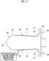
- a recessed portion 66 of a grip 65 shown in Fig. 11 includes a first surface 67 that is inclined to become closer to an inner side toward the connection end 25.
- the first surface 67 since the first surface 67 has a shape that further conforms to the gripping shape of the hand H, it is easier to grip the first surface 67 with the hand H.
- the first surface may not be a surface approximately parallel to the axial direction AD. The same applies to the second surface. In short, the first surface and the second surface only need to intersect each other.
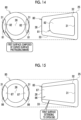
- a recessed portion 71 of a grip 70 shown in Fig. 12 includes a deep cut surface 72.
- the deep cut surface 72 is a surface obtained by deeply cutting a connection portion between the first surface 30 and the second surface 31 inwardly.
- the deep cut surface 72 is an example of a "curved surface" according to the present disclosed technology.
- it is possible to efficiently transmit a force by means of various gripping methods such as a method of gripping the deep cut surface 72 with a fingertip put on the deep cut surface 72 or a method of gripping the deep cut surface 72 with an index finger and a thumb hooked on the deep cut surface 72.
- the grip may have a truncated conical shape.
- a truncated cone is a three-dimensional shape obtained by cutting a cone along a plane parallel to a bottom surface and removing a small cone portion and a pudding is a representative example thereof. Since the truncated conical shape is also a shape that conforms to a gripping shape of the hand H, it is easy to grip the grips 75, 80, and 85 with the hand H.
- grips 75, 80, and 85 each having a truncated conical shape also, it is possible to fully exhibit an effect of being easily gripped by the hand H in the case of a gripping method in which the tapered portion 33 is wrapped with a palm as shown in Fig. 6 . Note that, as with the grip 16, corners of the grips 75, 80, and 85 are also rounded through R chamfering.
- a recessed portion 76 of the grip 75 shown in Fig. 13 includes the first surface 30, the second surface 31, and the connection surface 32.
- a recessed portion 81 of the grip 80 shown in Fig. 14 includes a first surface 82 composed of a curved surface protruding inward. Note that a first surface composed of a curved surface protruding outward like the first surface 57 shown in Fig. 9 may also be adopted instead of the first surface 82.
- a second surface composed of a curved surface protruding toward the connection end 25 like the second surface 62 shown in Fig. 10 may also be adopted instead of the second surface 31.
- a first surface that is inclined to become closer to the inner side toward the connection end 25 like the first surface 67 shown in Fig. 11 may also be adopted and a first surface and a second surface may be connected to each other by a curved surface like the deep cut surface 72 shown in Fig. 12 .
- a recessed portion 86 of a grip 85 shown in Fig. 15 includes a first surface 87 extending from a position near the connection end 25 to the open end 26. In the case of the first surface 87, it is easy to slide the finger F into the recessed portion 86.
- the grip may have a columnar shape.
- the grips 90 and 95 each having a columnar shape can be easily manufactured in comparison with the case of a shape that is obtained in a case where a portion of the prolate spheroid PS is cut along the short axial direction SAD and a truncated conical shape. Note that, as with the grip 16 and the like, corners of the grips 90 and 95 are also rounded through R chamfering.
- a recessed portion 91 of the grip 90 shown in Fig. 16 includes the first surface 30, the second surface 31, and the connection surface 32.
- a recessed portion 96 of the grip 95 shown in Fig. 17 includes a first surface 97 composed of a curved surface protruding inward. Note that a first surface composed of a curved surface protruding outward like the first surface 57 shown in Fig. 9 may also be adopted instead of the first surface 97.
- a second surface composed of a curved surface protruding toward the connection end 25 like the second surface 62 shown in Fig. 10 may also be adopted instead of the second surface 31.
- a first surface that is inclined to become closer to the inner side toward the connection end 25 like the first surface 67 shown in Fig. 11 may also be adopted and a first surface and a second surface may be connected to each other by a curved surface like the deep cut surface 72 shown in Fig. 12 .
- a first surface that extends from a position near the connection end 25 to the open end 26 like the first surface 87 shown in Fig. 15 may also be adopted.
- the second surface may not be provided.
- the recessed portion may include only a C-shaped first surface 102 that extends from the connection end 25 to the open end 26.
- the shape of the grip may be, for example, a polygonal frustum shape such as a quadrangular frustum shape, or a polygonal prism shape such as a quadrangular prism shape.
- the recessed portion further includes, in addition to the first surface and the second surface, a third surface that intersects the first surface and the second surface.
- the number of the recessed portions is not limited to two. For example, three recessed portions may be formed at portions 120° separated from each other in a plan view of the grip as seen in the axial direction AD.
- the term "A and/or B” is synonymous with the term “at least one of A or B”. That is, the term “A and/or B” means only A, only B, or a combination of A and B.
- the same approach as “A and/or B” is applied to a case where three or more matters are represented by connecting the matters with "and/or”.
Abstract
Provided is an obturator that includes a shaft that is inserted into a cannula and of which a distal end is sharp-pointed in a needle-like shape to be stuck into a body wall, a grip to which a proximal end of the shaft is attached and that is gripped by an operator, and at least two recessed portions that are formed at the grip and on which fingers of the operator are hooked.
Description
- The present disclosed technology relates to an obturator and a trocar.
- In surgery, a trocar is used. The trocar is composed of a cannula and an obturator. The cannula has a tubular shape with an insertion hole through which an endoscope and/or a treatment tool is guided into a body cavity. The obturator includes a shaft that is inserted into the insertion hole of the cannula and of which a distal end is sharp-pointed in a needle-like shape to be stuck into a body wall of a patient and a grip to which a proximal end of the shaft is attached and that is gripped by an operator. The operator separates the obturator from the cannula after sticking the shaft of the obturator into the body wall together with the cannula and then leaves the cannula alone in the body wall.
- Described in
JP2003-047618A - In the case of the obturator disclosed in
JP2003-047618A - An embodiment according to the present disclosed technology provides an obturator and a trocar improved in operation stability.
- An obturator according to an aspect of the present disclosure includes a shaft that is inserted into a cannula and of which a distal end is sharp-pointed in a needle-like shape to be stuck into a body wall, a grip to which a proximal end of the shaft is attached and that is gripped by an operator, and at least two recessed portions that are formed at the grip and on which fingers of the operator are hooked.
- It is preferable that the two recessed portions are formed at opposite positions on the grip.
- It is preferable that the recessed portion includes at least a first surface that is formed along an axial direction of the shaft and a second surface that is connected to the first surface on a connection end side and that intersects the first surface, the connection end being one end of the grip to which the proximal end of the shaft is attached.
- It is preferable that the first surface and the second surface are connected to each other by a curved surface.
- It is preferable that at least one of the first surface or the second surface includes a curved surface.
- It is preferable that the first surface extends from a position near the connection end to an open end, which is the other end of the grip and is on a side opposite to the connection end.
- It is preferable that the grip has a tapered shape of which a thickness decreases toward an open end from a connection end, the connection end being one end of the grip to which the proximal end of the shaft is attached and the open end being the other end of the grip that is on a side opposite to the connection end.
- It is preferable that the grip has a shape that is obtained in a case where a portion of a prolate spheroid is cut along a short axial direction or has a truncated conical shape.
- It is preferable that the grip has a columnar shape.
- It is preferable that a length of the grip in an axial direction of the shaft is 1.2 times or more and less than 1.5 times a length of the grip in a radial direction of the shaft.
- It is preferable that a length of the grip in an axial direction of the shaft is 40 mm or greater and smaller than 70 mm.
- It is preferable that the grip includes a notched portion in which at least a portion of a button for separation of the cannula is accommodated and that is disposed at a position different from a position of the recessed portion in a circumferential direction of the shaft.
- It is preferable that the grip includes a protrusion that is connected to the cannula and that is provided at a position corresponding to the recessed portion in a circumferential direction of the shaft.
- A trocar according to an aspect of the present disclosure includes any obturator described above and a cannula into which the obturator is attachably and detachably inserted.
- It is preferable that the cannula includes a cannula body that has a tubular shape with an insertion hole into which the shaft is inserted and a connecting portion to which a proximal end of the cannula body is attached, to which the grip is attachably and detachably connected, and of which a length in an axial direction of the shaft is shorter than a length of the grip in the axial direction.
- According to the present disclosed technology, it is possible to provide an obturator and a trocar improved in operation stability.
-
-
Fig. 1 is a perspective view of a trocar. -
Fig. 2 is an exploded perspective view of the trocar. -
Fig. 3 is a plan view of the trocar. -
Fig. 4 shows a side view and a front view of an obturator. -
Fig. 5 is a view showing a state immediately before a shaft of the obturator is stuck into a body wall together with a cannula. -
Fig. 6 is a view showing a state where the obturator is separated from a cannula and the cannula is left alone at a body wall. -
Fig. 7 is a flowchart showing the procedure for operating the trocar. -
Fig. 8 is a view showing a grip including a first surface composed of a curved surface protruding inward. -
Fig. 9 is a view showing a grip including a first surface composed of a curved surface protruding outward. -
Fig. 10 is a view showing a grip including a second surface composed of a curved surface protruding toward a connection end. -
Fig. 11 is a view showing a grip including a first surface that is inclined to become closer to an inner side toward the connection end. -
Fig. 12 is a view showing a grip including a deep cut surface obtained by deeply cutting a connection portion between a first surface and a second surface inwardly. -
Fig. 13 is a view showing a grip having a truncated conical shape. -
Fig. 14 is a view showing a truncated conical shape grip that includes a first surface composed of a curved surface protruding inward. -
Fig. 15 is a view showing a truncated conical grip that includes a first surface extending from a position near the connection end to an open end. -
Fig. 16 is a view showing a columnar grip. -
Fig. 17 is a view showing a columnar grip including a first surface composed of a curved surface protruding inward. -
Fig. 18 is a view showing another example of a grip. - For example, as shown in
Figs. 1 and2 , atrocar 10 is composed of acannula 11 and anobturator 12. Thecannula 11 includes acannula body 13 and a connectingportion 14. Theobturator 12 includes ashaft 15 and agrip 16. Note thatFig. 1 shows a state where thecannula 11 is mounted on theobturator 12 andFig. 2 shows a state where thecannula 11 is separated from theobturator 12. - The
cannula body 13 has a tubular shape with an insertion hole 17 into which theshaft 15 is inserted. The connectingportion 14 also has a tubular shape with aninsertion hole 18 that leads to the insertion hole 17. Theinsertion holes 17 and 18 have substantially the same diameter as each other. The connectingportion 14 has a diameter slightly larger than the diameter of thecannula body 13 and is attached to aproximal end 19 of thecannula body 13. Thegrip 16 is attachably and detachably connected to the connectingportion 14. - The connecting
portion 14 is provided with abutton 20. Thebutton 20 is operated by an operator in a case where thecannula 11 is to be separated from theobturator 12. In addition, at the connectingportion 14, twogrooves 21 are formed along an axial direction AD of theshaft 15. The twogrooves 21 are disposed at positions 180° separated from each other, that is, at positions facing each other in a plan view of the connectingportion 14 as seen in the axial direction AD of theshaft 15. Furthermore, the connectingportion 14 is provided with aport 29 through which a gas such as carbon dioxide is introduced into a body cavity. Although illustration and detailed description are omitted, the connectingportion 14 includes a latching mechanism for attachably and detachably holding thegrip 16, a seal for preventing a gas and liquid in a body cavity from leaking to the outside, and the like. Note that a body cavity is, for example, an abdominal cavity. - The
shaft 15 has an elongated rod-like shape with adistal end 22 and aproximal end 23 and is made of, for example, metal, such as a titanium alloy. Thedistal end 22 is sharp-pointed in a needle-like shape to be stuck into a body wall BW (refer toFigs. 5 and6 ) of a patient. The length of theshaft 15 in the axial direction AD is larger than the length of thecannula body 13 in the axial direction AD. Therefore, in a state where thecannula 11 is mounted on theobturator 12, thedistal end 22 of theshaft 15 protrudes from thecannula body 13 as shown inFig. 1 . Note that theshaft 15 may be made of a resin, such as an acrylonitrile-butadiene-styrene (ABS) resin. In addition, regarding theshaft 15, thedistal end 22 may be made of an ABS resin and a portion other than thedistal end 22 may be made of a different material, such as stainless steel, for example. - The
grip 16 is attached to theproximal end 23 of theshaft 15. A corner of thegrip 16 is rounded through R chamfering. Thegrip 16 is to be gripped by the operator (refer toFigs. 5 and6 ). Two recessedportions 24 are formed at thegrip 16. Each of the two recessedportions 24 is formed over an area from a position near aconnection end 25, which is one end of thegrip 16 and to which theproximal end 23 of theshaft 15 is attached, to a position near anopen end 26, which is the other end of thegrip 16 and is on a side opposite to theconnection end 25. The two recessedportions 24 are disposed at positions 180° separated from each other, that is, at positions facing each other in a plan view of thegrip 16 as seen in the axial direction AD of theshaft 15. Fingers of the operator are to be hooked on the recessed portions 24 (refer toFigs. 5 and6 ). Therefore, the recessedportions 24 can also be referred to as finger hooking portions. Note that the operator refers to all persons who operate thetrocar 10, such as a doctor who performs surgery using thetrocar 10. - The
connection end 25 is provided with a notchedportion 27. Approximately half of thebutton 20 is accommodated in the notchedportion 27. The notchedportion 27 is disposed at a position different from the positions of the recessedportions 24 in a circumferential direction CD of theshaft 15. Specifically, the notchedportion 27 is disposed at an intermediate position between the two recessedportions 24. In other words, in a plan view of thegrip 16 as seen in the axial direction AD of theshaft 15, the notchedportion 27 is disposed at aposition 90° separated from each of the two recessedportions 24 which are disposed at the positions 180° separated from each other. - In addition, the
connection end 25 is provided with two protrusions 28 (refer toFig. 4 as well). As with the recessedportions 24, the twoprotrusions 28 are disposed at positions 180° separated from each other, that is, at positions facing each other in a plan view of thegrip 16 as seen in the axial direction AD of theshaft 15. That is, the twoprotrusions 28 are provided at positions corresponding to the recessedportions 24 in the circumferential direction CD of theshaft 15. In a case where thecannula 11 is to be mounted on theobturator 12, the positions of thecannula 11 and theobturator 12 in the circumferential direction CD are adjusted such that theprotrusions 28 are fitted into thegrooves 21. That is, thegrooves 21 and theprotrusions 28 have a role of positioning thecannula 11 in the circumferential direction CD while thecannula 11 is being mounted on theobturator 12. - For example, as shown in
Figs. 3 and4 , each of the recessedportions 24 includes afirst surface 30 and asecond surface 31. Thefirst surface 30 is formed along the axial direction AD. Specifically, thefirst surface 30 is a surface approximately parallel to the axial direction AD. In contrast, thesecond surface 31 is formed along a radial direction RD of theshaft 15. Specifically, thesecond surface 31 is a surface approximately parallel to the radial direction RD. That is, thefirst surface 30 and thesecond surface 31 intersect each other. Thesecond surface 31 is connected to thefirst surface 30 via aconnection surface 32 on the connection end 25 side. Theconnection surface 32 is a curved surface that smoothly connects thefirst surface 30 and thesecond surface 31 to each other, and is an example of a "curved surface" according to the present disclosed technology. Although there are a plurality of radial directions RD, here, the radial direction RD refers to a direction orthogonal to thefirst surface 30. - The
grip 16 has a tapered shape of which the thickness decreases toward theopen end 26 from theconnection end 25. More specifically, as shown inFig. 4 , thegrip 16 has a shape that is obtained in a case where a portion (here, approximately half) of a prolate spheroid PS virtually represented by a two-dot chain line is cut along a short axial direction SAD which is the same direction as the radial direction RD. In the following description, a portion of thegrip 16 that is on theopen end 26 side, that is approximately half of thegrip 16, and that includes a tapered curved surface will be referred to as a taperedportion 33. Note that the prolate spheroid PS is a three-dimensional shape obtained in a case where an ellipse is rotated with the major axis as the rotation axis and a rugby ball is a representative example thereof. - As shown in hatched areas HC in
Fig. 4 , each of the recessedportions 24 is formed by cutting or scraping off a portion of thegrip 16 having a shape that is obtained in a case where approximately half of the prolate spheroid PS is cut along the short axial direction SAD. Therefore, the recessedportions 24 can also be referred to as cutting portions or scraped portions. In addition, the recessedportions 24 are level differences formed by cutting or scraping off a portion of thegrip 16. Therefore, the recessedportions 24 can also be referred to as level difference portions. - As shown in
Fig. 3 , a length LCAD of the connectingportion 14 in the axial direction AD is shorter than a length LGAD of thegrip 16 in the axial direction AD (LCAD < LGAD). In addition, as shown inFig. 4 , the length LGAD of thegrip 16 in the axial direction AD is 1.2 times or more and less than 1.5 times a length LGRD of thegrip 16 in the radial direction RD (1.2 LGRD ≤ LGAD < 1.5 LGRD). Furthermore, the length LGAD of thegrip 16 in the axial direction AD is 40 mm or greater and smaller than 70 mm (40 mm ≤ LGAD < 70 mm). For example, the length LGAD of thegrip 16 in the axial direction AD is 57 mm, and the length LGRD of thegrip 16 in the radial direction RD is 42 mm. In this case, since LGAD ≈ 1.36 LGRD, a condition that 1.2 LGRD ≤ LGAD < 1.5 LGRD is satisfied. In addition, the above-described condition that 40 mm ≤ LGAD < 70 mm is also satisfied. - For example, as shown in
Fig. 5 , in a case where thetrocar 10 is to be operated, the operator hooks fingers F of a hand H on the recessedportions 24 of thegrip 16.Fig. 5 shows a case where a thumb is hooked on one recessedportion 24 and a finger other than the thumb is hooked on the other recessedportion 24. More specifically, the tip of the thumb is brought into contact with thesecond surface 31 of the one recessedportion 24 and the pad of the thumb is brought into contact with thefirst surface 30 and theconnection surface 32 of the one recessedportion 24. In addition, the tip of at least one of fingers other than the thumb (for example, a middle finger) is brought into contact with thesecond surface 31 of the other recessedportion 24 and the pad of the finger other than the thumb is brought into contact with thefirst surface 30 and theconnection surface 32 of the other recessedportion 24. -
Fig. 5 shows a state immediately before theshaft 15 is stuck into the body wall BW together with thecannula 11. The operator causes thetrocar 10 to access the body wall BW by bringing thetrocar 10 down in an approximately perpendicular direction and, in some cases, the operator sticks theshaft 15 into the body wall BW up to a position where the connectingportion 14 reaches a surface of the body wall BW while rotating thetrocar 10 in the circumferential direction CD. A portion of the body wall BW into which theshaft 15 is stuck may be incised in advance with a scalpel. Note that the body wall BW is, for example, an abdominal wall. -
Fig. 6 shows a state where thecannula 11 is left alone at the body wall BW after theshaft 15 is stuck into the body wall BW up to a position where the connectingportion 14 reaches the surface of the body wall BW and then theobturator 12 is separated from thecannula 11. In this case, the operator switches from a gripping method as shown inFig. 5 to a gripping method of wrapping the grip 16 (particularly, the tapered portion 33) with a palm of a hand as shown in the drawing. More specifically, the operator puts a thumb at a position between the two recessedportions 24 at which thebutton 20 is disposed, wraps an index finger, a middle finger, and a ring finger around the other recessedportion 24 side, and folds the index finger, the middle finger, and the ring finger. Furthermore, a little finger is folded along with the ring finger. The operator operates thebutton 20 with the tip of the thumb as represented by a broken line to disconnect the connectingportion 14 and thegrip 16 from each other, that is, to disconnect thecannula 11 and theobturator 12 from each other. Then, the operator separates theobturator 12 from thecannula 11 by pulling theobturator 12 in a direction opposite to a direction in which theshaft 15 is stuck into the body wall BW and leaves thecannula 11 alone at the body wall BW. As understood from the above description, the taperedportion 33 can be referred to as a palm-wrapped portion as well. In addition, the taperedportion 33 can be referred to as a curved surface portion as well. -
Fig. 7 is a flowchart showing an example of the procedure for operating thetrocar 10. First, the operator mounts thecannula 11 on the obturator 12 (Step ST100). In this case, the operator adjusts the positions of thecannula 11 and theobturator 12 in the circumferential direction CD such that theprotrusions 28 are fitted into thegrooves 21 and thebutton 20 is accommodated in the notchedportion 27. - Next, as shown in
Fig. 5 , the operator hooks fingers F on the recessedportions 24 of thegrip 16 and sticks theshaft 15 into the body wall BW together with thecannula 11 while gripping the grip 16 (Step ST110). - After the
shaft 15 is stuck into the body wall BW up to a position where the connectingportion 14 reaches the surface of the body wall BW, the operator operates thebutton 20 as shown inFig. 6 so that theobturator 12 is separated from thecannula 11 and thecannula 11 is left alone at the body wall BW (Step ST120). Thereafter, the operator performs, for example, introduction of an endoscope and/or a treatment tool into the insertion holes 17 and 18 of thecannula 11 and performs surgery on the patient. - As described above, the
obturator 12 includes theshaft 15, thegrip 16, and the recessedportions 24. Theshaft 15 is inserted into thecannula 11, and thedistal end 22 thereof is sharp-pointed in a needle-like shape to be stuck into the body wall BW. Theproximal end 23 of theshaft 15 is attached to thegrip 16 and thegrip 16 is gripped by the operator. Two recessedportions 24 are formed at thegrip 16, and the fingers F of the operator are hooked on the recessedportions 24. Therefore, theobturator 12 can be further improved in terms of operation stability in comparison with an obturator disclosed inJP2003-047618A - As shown in
Fig. 1 and the like, the two recessedportions 24 are formed at opposite positions on thegrip 16. Therefore, thegrip 16 can be formed in a simple and symmetrical shape. - As shown in
Fig. 3 and the like, each of the recessedportion 24 includes thefirst surface 30 that is formed along the axial direction AD of theshaft 15 and thesecond surface 31 that is connected to thefirst surface 30 on the connection end 25 side, the connection end 25 being one end of the grip to which theproximal end 23 of theshaft 15 is attached. Thesecond surface 31 intersects thefirst surface 30. With thefirst surface 30, a force that rotates theshaft 15 in the circumferential direction CD can be efficiently transmitted in a case where theshaft 15 is stuck into the body wall BW. In addition, with thesecond surface 31, a force that pushes theshaft 15 in a direction in which theshaft 15 is stuck can be efficiently transmitted in a case where theshaft 15 is stuck into the body wall BW. - As shown in
Fig. 3 and the like, thefirst surface 30 and thesecond surface 31 are connected to each other by theconnection surface 32 which is a curved surface. Therefore, it is possible to smoothly apply, with one finger, a force to thefirst surface 30 that rotates theshaft 15 in the circumferential direction CD and a force to thesecond surface 31 that pushes theshaft 15 in a direction in which theshaft 15 is stuck in comparison with a case where thefirst surface 30 and thesecond surface 31 are connected to each other at an angle. In addition, it is possible to prevent dust from accumulating in a connection portion between thefirst surface 30 and thesecond surface 31 in comparison with a case where thefirst surface 30 and thesecond surface 31 are connected at an angle. Furthermore, it is possible to easily clean the connection portion between thefirst surface 30 and thesecond surface 31 in comparison with a case where thefirst surface 30 and thesecond surface 31 are connected at an angle. Therefore, it is possible to maintain the cleanliness of the connection portion between thefirst surface 30 and thesecond surface 31. - As shown in
Fig. 1 and the like, thegrip 16 has a tapered shape (the tapered portion 33) of which the thickness decreases toward theopen end 26 from theconnection end 25. Since this shape is a shape that conforms to a gripping shape of the hand H, it is easy to grip thegrip 16 with the hand H. Particularly, in the case of a gripping method in which the taperedportion 33 is wrapped with a palm as shown inFig. 6 , it is possible to fully exhibit an effect of being easily gripped by the hand H. - As shown in
Fig. 4 , thegrip 16 has a shape obtained in a case where a portion of the prolate spheroid PS is cut along the short axial direction SAD. In this case, theopen end 26 of thegrip 16 has a rounded shape (the tapered portion 33) and thus there is no burden imposed on the palm of the hand H even in a case where the palm comes into contact with theopen end 26. - As shown in
Fig. 4 , the length LGAD of thegrip 16 in the axial direction AD is 1.2 times or more and less than 1.5 times the length LGRD of thegrip 16 in the radial direction RD. In a case where the length LGAD is 1.2 times or more and less than 1.5 times the length LGRD, it is easy to grip thegrip 16 with the hand H and to operate the obturator 12 (the trocar 10). On the contrary, in a case where the length LGAD is less than 1.2 times or 1.5 times or more the length LGRD, it is difficult to grip thegrip 16 with the hand H and to operate the obturator 12 (trocar 10). - In addition, as shown in
Fig. 4 , the length LGAD of thegrip 16 in the axial direction AD is 40 mm or greater and smaller than 70 mm. In a case where the length LGAD is 40 mm or greater and less than 70 mm, it is easy to grip thegrip 16 with the hand H and to operate the obturator 12 (trocar 10). On the contrary, in a case where the length LGAD is less than 40 mm or 70 mm or more, it is difficult to grip thegrip 16 with the hand H and to operate the obturator 12 (trocar 10). - As shown in
Fig. 1 , thegrip 16 includes the notchedportion 27 in which at least a portion of thebutton 20 for separation of thecannula 11 is accommodated and that is disposed at a position different from the positions of the recessedportions 24 in the circumferential direction CD. Therefore, the recessedportions 24 and the notchedportion 27 do not interfere with each other and thus it is possible to reduce a probability that thebutton 20 is erroneously operated by the fingers F hooked on the recessedportions 24. - The
grip 16 includes theprotrusions 28 that are connected to thecannula 11 and that are provided at positions corresponding to the recessedportions 24 in the circumferential direction CD. Therefore, theprotrusions 28 can be easily visually recognized in a case where thecannula 11 is to be mounted on theobturator 12, and it is possible to easily adjust the positions of thecannula 11 and theobturator 12 in the circumferential direction CD such that theprotrusions 28 are fitted into thegrooves 21. - As shown in
Fig. 1 and the like, thecannula 11 includes thecannula body 13 that has a tubular shape with the insertion hole 17 into which theshaft 15 is inserted and the connectingportion 14 to which theproximal end 19 of thecannula body 13 is attached and to which thegrip 16 is attachably and detachably connected. As shown inFig. 3 , the length LCAD of the connectingportion 14 in the axial direction is shorter than the length LGAD of thegrip 16 in the axial direction AD. Therefore, it is possible to operate thetrocar 10 with thegrip 16 having a size relatively larger than the size of the connectingportion 14 and to improve the operation stability in comparison with the case of thegrip 16 having a size relatively smaller than the size of the connectingportion 14. - The
button 20 for separation of thecannula 11 from theobturator 12 may be provided at thegrip 16 instead of the connectingportion 14. In addition, the notchedportion 27 may not be provided. - Modification examples of the grip will be described below. Note that, hereinafter, parts different from the above-described embodiments will be mainly described, and the same parts as those of the above-described embodiment or parts that do not need to be distinguished from each other are given the same reference numerals as those of the above-described embodiment and the description thereof will be omitted.
- For example, a recessed
portion 51 of agrip 50 shown inFig. 8 includes afirst surface 52 composed of a curved surface protruding inward. On the contrary, for example, a recessedportion 56 of agrip 55 shown inFig. 9 includes afirst surface 57 composed of a curved surface protruding outward. In the case of the recessedportion 51 shown inFig. 8 , the feeling of fitting of the finger F can be enhanced since the shape of thefirst surface 52 coincides with the shape of the pad of the finger F. On the other hand, in the case of the recessedportion 56 shown inFig. 9 , since thefirst surface 57 has a shape that further conforms to the gripping shape of the hand H, it is easier to grip thefirst surface 57 with the hand H. - In
Figs. 8 and9 , the recessedportions first surfaces portion 61 of agrip 60 shown inFig. 10 , asecond surface 62 composed of a curved surface protruding toward theconnection end 25 may also be provided. In the case of the recessedportion 61, since thesecond surface 62 coincides with the shape of a fingertip, the feeling of fitting of the finger F can be enhanced. Note that, a second surface that is composed of a curved surface protruding toward theopen end 26 unlike thesecond surface 62 may also be adopted. As described above, at least one of the first surface or the second surface may include a curved surface. - For example, a recessed
portion 66 of agrip 65 shown inFig. 11 includes afirst surface 67 that is inclined to become closer to an inner side toward theconnection end 25. In the case of the recessedportion 66, since thefirst surface 67 has a shape that further conforms to the gripping shape of the hand H, it is easier to grip thefirst surface 67 with the hand H. As described above, the first surface may not be a surface approximately parallel to the axial direction AD. The same applies to the second surface. In short, the first surface and the second surface only need to intersect each other. - In addition, for example, a recessed
portion 71 of agrip 70 shown inFig. 12 includes adeep cut surface 72. Thedeep cut surface 72 is a surface obtained by deeply cutting a connection portion between thefirst surface 30 and thesecond surface 31 inwardly. Thedeep cut surface 72 is an example of a "curved surface" according to the present disclosed technology. In the case of the recessedportion 71, it is possible to efficiently transmit a force by means of various gripping methods such as a method of gripping thedeep cut surface 72 with a fingertip put on thedeep cut surface 72 or a method of gripping thedeep cut surface 72 with an index finger and a thumb hooked on thedeep cut surface 72. - Hereinabove, a shape obtained in a case where a portion of the prolate spheroid PS is cut along the short axial direction SAD has been used as an example of the shape of the grip. However, the present disclosed technology is not limited thereto.
- As in the case of a
grip 75 shown inFig. 13 as an example, agrip 80 shown inFig. 14 as an example, and agrip 85 shown inFig. 15 as an example, the grip may have a truncated conical shape. A truncated cone is a three-dimensional shape obtained by cutting a cone along a plane parallel to a bottom surface and removing a small cone portion and a pudding is a representative example thereof. Since the truncated conical shape is also a shape that conforms to a gripping shape of the hand H, it is easy to grip thegrips grips portion 33 is wrapped with a palm as shown inFig. 6 . Note that, as with thegrip 16, corners of thegrips - As with the
grip 16, a recessedportion 76 of thegrip 75 shown inFig. 13 includes thefirst surface 30, thesecond surface 31, and theconnection surface 32. A recessedportion 81 of thegrip 80 shown inFig. 14 includes afirst surface 82 composed of a curved surface protruding inward. Note that a first surface composed of a curved surface protruding outward like thefirst surface 57 shown inFig. 9 may also be adopted instead of thefirst surface 82. In addition, a second surface composed of a curved surface protruding toward the connection end 25 like thesecond surface 62 shown inFig. 10 may also be adopted instead of thesecond surface 31. Furthermore, a first surface that is inclined to become closer to the inner side toward the connection end 25 like thefirst surface 67 shown inFig. 11 may also be adopted and a first surface and a second surface may be connected to each other by a curved surface like thedeep cut surface 72 shown inFig. 12 . - A recessed
portion 86 of agrip 85 shown inFig. 15 includes afirst surface 87 extending from a position near theconnection end 25 to theopen end 26. In the case of thefirst surface 87, it is easy to slide the finger F into the recessedportion 86. - As in the case of a
grip 90 shown inFig. 16 as an example and agrip 95 shown inFig. 17 as an example, the grip may have a columnar shape. Thegrips grip 16 and the like, corners of thegrips - As with the
grips portion 91 of thegrip 90 shown inFig. 16 includes thefirst surface 30, thesecond surface 31, and theconnection surface 32. A recessedportion 96 of thegrip 95 shown inFig. 17 includes afirst surface 97 composed of a curved surface protruding inward. Note that a first surface composed of a curved surface protruding outward like thefirst surface 57 shown inFig. 9 may also be adopted instead of thefirst surface 97. In addition, a second surface composed of a curved surface protruding toward the connection end 25 like thesecond surface 62 shown inFig. 10 may also be adopted instead of thesecond surface 31. Furthermore, a first surface that is inclined to become closer to the inner side toward the connection end 25 like thefirst surface 67 shown inFig. 11 may also be adopted and a first surface and a second surface may be connected to each other by a curved surface like thedeep cut surface 72 shown inFig. 12 . In addition, a first surface that extends from a position near theconnection end 25 to theopen end 26 like thefirst surface 87 shown inFig. 15 may also be adopted. - The second surface may not be provided. For example, as in the case of a recessed
portion 101 of thegrip 100 shown inFig. 18 , the recessed portion may include only a C-shapedfirst surface 102 that extends from theconnection end 25 to theopen end 26. - The shape of the grip may be, for example, a polygonal frustum shape such as a quadrangular frustum shape, or a polygonal prism shape such as a quadrangular prism shape. In such cases, the recessed portion further includes, in addition to the first surface and the second surface, a third surface that intersects the first surface and the second surface. In addition, the number of the recessed portions is not limited to two. For example, three recessed portions may be formed at portions 120° separated from each other in a plan view of the grip as seen in the axial direction AD.
- Regarding the present disclosed technology, the above-described various embodiments and/or various modification examples can be combined with each other as appropriate. In addition, it is a matter of course that the present disclosed technology is not limited to the above-described embodiment and various configurations can be adopted without departing from the gist.
- Contents described and illustrated above are for detailed description of a part according to the present disclosed technology and are merely an example of the present disclosed technology. For example, description of the above-described configurations, functions, actions, and effects is description related to an example of configurations, functions, actions, and effects of a part according to the present disclosed technology. Therefore, it is a matter of course that an unnecessary part of the contents described and illustrated above may be deleted, a new element may be added, and replacement may be made without departing from the spirit of the present disclosed technology. In addition, in order to avoid complication and facilitate the understanding of a portion according to the present disclosed technology, regarding the contents described and illustrated above, description related to common technical knowledge or the like which does not need to be described to enable implementation of the present disclosed technology has been omitted.
- In the present specification, the term "A and/or B" is synonymous with the term "at least one of A or B". That is, the term "A and/or B" means only A, only B, or a combination of A and B. In addition, in the present specification, the same approach as "A and/or B" is applied to a case where three or more matters are represented by connecting the matters with "and/or".
- All documents, patent applications, and technical standards described in the present specification are incorporated in the present specification by reference to the same extent as in a case where each of the documents, patent applications, technical standards are specifically and individually indicated to be incorporated by reference.
Claims (15)
- An obturator comprising:a shaft that is inserted into a cannula and of which a distal end is sharp-pointed in a needle-like shape to be stuck into a body wall;a grip to which a proximal end of the shaft is attached and that is gripped by an operator; andat least two recessed portions that are formed at the grip and on which fingers of the operator are hooked.
- The obturator according to claim 1,
wherein the two recessed portions are formed at opposite positions on the grip. - The obturator according to claim 1 or 2,wherein the recessed portion includes at leasta first surface that is formed along an axial direction of the shaft, anda second surface that is connected to the first surface on a connection end side and that intersects the first surface, the connection end being one end of the grip to which the proximal end of the shaft is attached.
- The obturator according to claim 3,
wherein the first surface and the second surface are connected to each other by a curved surface. - The obturator according to claim 3 or 4,
wherein at least one of the first surface or the second surface includes a curved surface. - The obturator according to any one of claims 3 to 5,
wherein the first surface extends from a position near the connection end to an open end, which is the other end of the grip and is on a side opposite to the connection end. - The obturator according to any one of claims 1 to 6,
wherein the grip has a tapered shape of which a thickness decreases toward an open end from a connection end, the connection end being one end of the grip to which the proximal end of the shaft is attached and the open end being the other end of the grip that is on a side opposite to the connection end. - The obturator according to claim 7,
wherein the grip has a shape that is obtained in a case where a portion of a prolate spheroid is cut along a short axial direction or has a truncated conical shape. - The obturator according to any one of claims 1 to 6,
wherein the grip has a columnar shape. - The obturator according to any one of claims 1 to 9,
wherein a length of the grip in an axial direction of the shaft is 1.2 times or more and less than 1.5 times a length of the grip in a radial direction of the shaft. - The obturator according to any one of claims 1 to 10,
wherein a length of the grip in an axial direction of the shaft is 40 mm or greater and smaller than 70 mm. - The obturator according to any one of claims 1 to 11,
wherein the grip includes a notched portion in which at least a portion of a button for separation of the cannula is accommodated and that is disposed at a position different from a position of the recessed portion in a circumferential direction of the shaft. - The obturator according to any one of claims 1 to 12,
wherein the grip includes a protrusion that is connected to the cannula and that is provided at a position corresponding to the recessed portion in a circumferential direction of the shaft. - A trocar comprising:the obturator according to any one of claims 1 to 13; anda cannula into which the obturator is attachably and detachably inserted.
- The trocar according to claim 14,
wherein the cannula includesa cannula body that has a tubular shape with an insertion hole into which the shaft is inserted, anda connecting portion to which a proximal end of the cannula body is attached, to which the grip is attachably and detachably connected, and of which a length in an axial direction of the shaft is shorter than a length of the grip in the axial direction.
Applications Claiming Priority (2)
| Application Number | Priority Date | Filing Date | Title |
|---|---|---|---|
| JP2021091900 | 2021-05-31 | ||
| PCT/JP2022/017108 WO2022254964A1 (en) | 2021-05-31 | 2022-04-05 | Obturator and trocar |
Publications (1)
| Publication Number | Publication Date |
|---|---|
| EP4349286A1 true EP4349286A1 (en) | 2024-04-10 |
Family
ID=84323148
Family Applications (1)
| Application Number | Title | Priority Date | Filing Date |
|---|---|---|---|
| EP22815720.2A Pending EP4349286A1 (en) | 2021-05-31 | 2022-04-05 | Obturator and trocar |
Country Status (5)
| Country | Link |
|---|---|
| US (1) | US20240081861A1 (en) |
| EP (1) | EP4349286A1 (en) |
| JP (1) | JPWO2022254964A1 (en) |
| CN (1) | CN117396147A (en) |
| WO (1) | WO2022254964A1 (en) |
Family Cites Families (6)
| Publication number | Priority date | Publication date | Assignee | Title |
|---|---|---|---|---|
| US5176648A (en) * | 1991-12-13 | 1993-01-05 | Unisurge, Inc. | Introducer assembly and instrument for use therewith |
| JP3402643B2 (en) * | 1992-04-14 | 2003-05-06 | オリンパス光学工業株式会社 | Trocar |
| JPH09253087A (en) * | 1996-03-22 | 1997-09-30 | Olympus Optical Co Ltd | Ultrasonic trocar |
| US20030004529A1 (en) | 2001-06-28 | 2003-01-02 | Mark Tsonton | Trocar having an improved seal design |
| US8715219B2 (en) * | 2008-10-10 | 2014-05-06 | Surgiquest, Inc. | System and method for improved gas recirculation in surgical trocars with pneumatic sealing |
| US8753269B2 (en) * | 2009-04-23 | 2014-06-17 | Medtronic, Inc. | Minimally invasive access device for heart valve procedures |
-
2022
- 2022-04-05 CN CN202280038465.9A patent/CN117396147A/en active Pending
- 2022-04-05 WO PCT/JP2022/017108 patent/WO2022254964A1/en active Application Filing
- 2022-04-05 JP JP2023525645A patent/JPWO2022254964A1/ja active Pending
- 2022-04-05 EP EP22815720.2A patent/EP4349286A1/en active Pending
-
2023
- 2023-11-22 US US18/518,362 patent/US20240081861A1/en active Pending
Also Published As
| Publication number | Publication date |
|---|---|
| CN117396147A (en) | 2024-01-12 |
| JPWO2022254964A1 (en) | 2022-12-08 |
| WO2022254964A1 (en) | 2022-12-08 |
| US20240081861A1 (en) | 2024-03-14 |
Similar Documents
| Publication | Publication Date | Title |
|---|---|---|
| US20230248389A1 (en) | Exchanger surgical access port and methods of use | |
| AU749818B2 (en) | Trocar having protector with flexible end | |
| EP1420705B1 (en) | Trocar requiring minimal insertion force | |
| US5658306A (en) | Method for making additional incisions in laparoscopic surgery | |
| JP2580018B2 (en) | Trocar assembly | |
| US5009643A (en) | Self-retaining electrically insulative trocar sleeve and trocar | |
| JP2012130677A (en) | Self-expanding opening part protector for body | |
| JP2010522626A (en) | Fixable cannula and method of fixing cannula | |
| US6663605B2 (en) | Removable protective cannula for use in surgery | |
| US9795409B2 (en) | Trocar device and use thereof | |
| US20210338281A1 (en) | Multi-diameter cannula depth limiter | |
| JP6387479B2 (en) | Endoscope cover and endoscope | |
| EP4349286A1 (en) | Obturator and trocar | |
| JP2003061970A (en) | Trocar mantle tube | |
| KR102032510B1 (en) | Medical Trcar | |
| US5667519A (en) | Knife for laparoscopic surgery | |
| KR20150101957A (en) | overtube AND USES THEREOF | |
| WO2018070409A1 (en) | Nose knife | |
| JPH0819550A (en) | Cannula and trocar having this | |
| WO2022093451A1 (en) | Distal tips of surgical tools and related methods |
Legal Events
| Date | Code | Title | Description |
|---|---|---|---|
| STAA | Information on the status of an ep patent application or granted ep patent |
Free format text: STATUS: THE INTERNATIONAL PUBLICATION HAS BEEN MADE |
|
| PUAI | Public reference made under article 153(3) epc to a published international application that has entered the european phase |
Free format text: ORIGINAL CODE: 0009012 |
|
| STAA | Information on the status of an ep patent application or granted ep patent |
Free format text: STATUS: REQUEST FOR EXAMINATION WAS MADE |
|
| 17P | Request for examination filed |
Effective date: 20231128 |
|
| AK | Designated contracting states |
Kind code of ref document: A1 Designated state(s): AL AT BE BG CH CY CZ DE DK EE ES FI FR GB GR HR HU IE IS IT LI LT LU LV MC MK MT NL NO PL PT RO RS SE SI SK SM TR |