EP4345358B1 - Aktives schwingungsdämpfungssystem für ein präzisionsbewegungssystem - Google Patents
Aktives schwingungsdämpfungssystem für ein präzisionsbewegungssystem Download PDFInfo
- Publication number
- EP4345358B1 EP4345358B1 EP22199078.1A EP22199078A EP4345358B1 EP 4345358 B1 EP4345358 B1 EP 4345358B1 EP 22199078 A EP22199078 A EP 22199078A EP 4345358 B1 EP4345358 B1 EP 4345358B1
- Authority
- EP
- European Patent Office
- Prior art keywords
- active
- screw
- mounting base
- active bearing
- supporting frame
- Prior art date
- Legal status (The legal status is an assumption and is not a legal conclusion. Google has not performed a legal analysis and makes no representation as to the accuracy of the status listed.)
- Active
Links
Images


Classifications
-
- F—MECHANICAL ENGINEERING; LIGHTING; HEATING; WEAPONS; BLASTING
- F16—ENGINEERING ELEMENTS AND UNITS; GENERAL MEASURES FOR PRODUCING AND MAINTAINING EFFECTIVE FUNCTIONING OF MACHINES OR INSTALLATIONS; THERMAL INSULATION IN GENERAL
- F16F—SPRINGS; SHOCK-ABSORBERS; MEANS FOR DAMPING VIBRATION
- F16F15/00—Suppression of vibrations in systems; Means or arrangements for avoiding or reducing out-of-balance forces, e.g. due to motion
- F16F15/02—Suppression of vibrations of non-rotating, e.g. reciprocating systems; Suppression of vibrations of rotating systems by use of members not moving with the rotating systems
- F16F15/03—Suppression of vibrations of non-rotating, e.g. reciprocating systems; Suppression of vibrations of rotating systems by use of members not moving with the rotating systems using magnetic or electromagnetic means
-
- F—MECHANICAL ENGINEERING; LIGHTING; HEATING; WEAPONS; BLASTING
- F16—ENGINEERING ELEMENTS AND UNITS; GENERAL MEASURES FOR PRODUCING AND MAINTAINING EFFECTIVE FUNCTIONING OF MACHINES OR INSTALLATIONS; THERMAL INSULATION IN GENERAL
- F16F—SPRINGS; SHOCK-ABSORBERS; MEANS FOR DAMPING VIBRATION
- F16F15/00—Suppression of vibrations in systems; Means or arrangements for avoiding or reducing out-of-balance forces, e.g. due to motion
- F16F15/02—Suppression of vibrations of non-rotating, e.g. reciprocating systems; Suppression of vibrations of rotating systems by use of members not moving with the rotating systems
-
- F—MECHANICAL ENGINEERING; LIGHTING; HEATING; WEAPONS; BLASTING
- F16—ENGINEERING ELEMENTS AND UNITS; GENERAL MEASURES FOR PRODUCING AND MAINTAINING EFFECTIVE FUNCTIONING OF MACHINES OR INSTALLATIONS; THERMAL INSULATION IN GENERAL
- F16M—FRAMES, CASINGS OR BEDS OF ENGINES, MACHINES OR APPARATUS, NOT SPECIFIC TO ENGINES, MACHINES OR APPARATUS PROVIDED FOR ELSEWHERE; STANDS; SUPPORTS
- F16M7/00—Details of attaching or adjusting engine beds, frames, or supporting-legs on foundation or base; Attaching non-moving engine parts, e.g. cylinder blocks
-
- F—MECHANICAL ENGINEERING; LIGHTING; HEATING; WEAPONS; BLASTING
- F16—ENGINEERING ELEMENTS AND UNITS; GENERAL MEASURES FOR PRODUCING AND MAINTAINING EFFECTIVE FUNCTIONING OF MACHINES OR INSTALLATIONS; THERMAL INSULATION IN GENERAL
- F16B—DEVICES FOR FASTENING OR SECURING CONSTRUCTIONAL ELEMENTS OR MACHINE PARTS TOGETHER, e.g. NAILS, BOLTS, CIRCLIPS, CLAMPS, CLIPS OR WEDGES; JOINTS OR JOINTING
- F16B5/00—Joining sheets or plates, e.g. panels, to one another or to strips or bars parallel to them
- F16B5/02—Joining sheets or plates, e.g. panels, to one another or to strips or bars parallel to them by means of fastening members using screw-thread
- F16B5/0208—Joining sheets or plates, e.g. panels, to one another or to strips or bars parallel to them by means of fastening members using screw-thread using panel fasteners, i.e. permanent attachments allowing for quick assembly
-
- F—MECHANICAL ENGINEERING; LIGHTING; HEATING; WEAPONS; BLASTING
- F16—ENGINEERING ELEMENTS AND UNITS; GENERAL MEASURES FOR PRODUCING AND MAINTAINING EFFECTIVE FUNCTIONING OF MACHINES OR INSTALLATIONS; THERMAL INSULATION IN GENERAL
- F16F—SPRINGS; SHOCK-ABSORBERS; MEANS FOR DAMPING VIBRATION
- F16F2226/00—Manufacturing; Treatments
- F16F2226/04—Assembly or fixing methods; methods to form or fashion parts
-
- F—MECHANICAL ENGINEERING; LIGHTING; HEATING; WEAPONS; BLASTING
- F16—ENGINEERING ELEMENTS AND UNITS; GENERAL MEASURES FOR PRODUCING AND MAINTAINING EFFECTIVE FUNCTIONING OF MACHINES OR INSTALLATIONS; THERMAL INSULATION IN GENERAL
- F16F—SPRINGS; SHOCK-ABSORBERS; MEANS FOR DAMPING VIBRATION
- F16F2230/00—Purpose; Design features
- F16F2230/0005—Attachment, e.g. to facilitate mounting onto confer adjustability
-
- F—MECHANICAL ENGINEERING; LIGHTING; HEATING; WEAPONS; BLASTING
- F16—ENGINEERING ELEMENTS AND UNITS; GENERAL MEASURES FOR PRODUCING AND MAINTAINING EFFECTIVE FUNCTIONING OF MACHINES OR INSTALLATIONS; THERMAL INSULATION IN GENERAL
- F16F—SPRINGS; SHOCK-ABSORBERS; MEANS FOR DAMPING VIBRATION
- F16F2230/00—Purpose; Design features
- F16F2230/36—Holes, slots or the like
-
- F—MECHANICAL ENGINEERING; LIGHTING; HEATING; WEAPONS; BLASTING
- F16—ENGINEERING ELEMENTS AND UNITS; GENERAL MEASURES FOR PRODUCING AND MAINTAINING EFFECTIVE FUNCTIONING OF MACHINES OR INSTALLATIONS; THERMAL INSULATION IN GENERAL
- F16F—SPRINGS; SHOCK-ABSORBERS; MEANS FOR DAMPING VIBRATION
- F16F2230/00—Purpose; Design features
- F16F2230/46—Maintenance
Definitions
- the present invention relates to an active anti-vibration system comprising a mounting base for a precision motion system, in particular for a semiconductor processing equipment.
- the anti-vibration system comprises active bearings for isolating the mounting base from ground vibrations and imparting counteracting forces to the mounting base to compensate for reactions forces generated by the precision motion system when operating.
- the active anti-vibration system is adapted for easy replacement of an active bearing in case of failure.
- the invention also relates to a method for disassembling an active bearing from the active anti-vibration system for its replacement.
- Precision motion systems in particular semiconductor processing equipment such as positioning devices, coordinate measuring machines or robots, comprise active anti-vibration systems, as disclosed in US6021991 or KR20120022572A , for isolating precision motion systems from ground vibrations.
- Active anti-vibration systems typically comprise several active bearings which are assembled between a granite base onto which the precision motion system can be mounted and a metallic frame that rests on the floor. Active anti-vibration systems therefore ensure the operation of precision motion systems with as little parasitic movement as possible, as a result of which a high positioning or measurement accuracy is obtained.
- Each active bearing comprises linear motors, vertical and horizontal sensors that are connected to electronic controllers to drive each linear motor as a function of the output of vertical and horizontal sensors and as a function of the known movements of the precision motion system to avoid unwanted movements of the granite base and dampen any residual movements.
- the active bearings support the granite base upwardly using a mechanical spring or an air spring, thereby passively isolating the base from the floor vibrations.
- An aim of the present invention is therefore to provide an active anti-vibration system for a precision motion system, adapted for easy replacement of active bearings in case of failure.
- Another aim of the present invention is to provide a method for disassembling an active bearing from the active anti-vibration system for easy replacement of the active bearing.
- each of the first set of fixation elements is in the form of a screw.
- the upper panel comprises threaded through-holes axially aligned with respective through-holes of the mounting base and receiving a threaded part of respective screws.
- each through-hole of the mounting base comprises an upper portion having a first diameter and a lower portion having a second diameter smaller than the first diameter to form a shoulder onto which the screw head of a corresponding screw rests to secure the active bearing upper panel to the lower side of the mounting base.
- each of said second set of fixation elements is in the form of a screw.
- the lower panel of each active bearing comprises trough-holes and captive screw retainers.
- Each captive screw retainer comprises a housing lodging a screw engaged with respective through-hole of the lower panel of the active bearing.
- the housing comprises an upper portion having a central opening axially aligned with the screw head of the screw.
- the upper side of the supporting frame comprises threaded holes receiving a threaded part of the screw of respective captive screw retainer.
- each active bearing lower panel is axially aligned with respective threaded through-holes of each active bearing upper panel.
- each captive screw retainer further comprises a magnet arranged to hold the screw when said screw is removed from the corresponding threaded hole of the upper side of the supporting frame during the disassembly of the corresponding active bearing for its replacement.
- Another aspect of the invention relates to a method for disassembling and removing an active bearing from the active bearing compartment of the active anti-vibration system as described above.
- the method comprises the steps of:
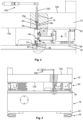
- the active anti-vibration system 10 comprises a mounting base 12 having an upper side 12a onto which a precision motion system, for example a semiconductor processing equipment, can be mounted.
- the mounting base 12 is preferably in granite and comprises multiple threaded holes for fixing different type of precision motion systems.
- the mounting base 12 may further comprise a support 16 for installing an optical imaging device, such as a microscope for visual inspection.
- the active anti-vibration system 10 further comprises a supporting frame 18 resting on the floor, and active bearings 30 mounted into an active bearing compartment 26 between the mounting base 12 and the supporting frame 18.
- Each active bearing 30 comprises a mechanical spring or an air spring (not shown) to support the mounting base, and passively isolate the base from the floor vibrations.
- the active bearing 30 comprises inertial sensors and actuators to provide together a six degrees-of-freedom (DOF) measurement of the motions of the mounting base 12 as well as six-DOF actuation devices.
- DOF degrees-of-freedom
- Six-DOF measurement is obtained with six or more inertial sensors shared out among the active bearings.
- Six-DOF actuation can be realized with six or more actuators shared out among the active bearings.
- three active bearings comprise each a horizontal and a vertical actuator, and a horizontal and a vertical inertial sensor, and the fourth active bearing comprises a horizontal and a vertical actuator only.
- the sensors and actuators are built into an active damping multiple-inputs/multiple-outputs (MIMO) control loop that dampens any residual vibrations of the granite base.
- MIMO multiple-inputs/multiple-outputs
- An active feedforward path is implemented which uses the known motions of the motion system to compute forces and torques to be applied by the actuators to the mounting base to compensate for reaction forces and thus avoid unwanted motions of the base.
- Each active bearing 30 further comprises an upper panel 32 mounted against the lower side 12b of the mounting base 12, and a lower panel 36 mounted against the upper side 19 of the supporting frame 18.
- the mounting base 12 of the active anti-vibration system 10 comprises through-holes 13 extending from the upper side 12a to the lower side 12b of the mounting base 12.
- Each through-hole 13 of the mounting base 12 comprises an upper portion having a first diameter d1 and a lower portion having a second diameter d2 smaller than the first diameter d1 to form a shoulder 14.
- a first set of fixation elements 15 are arranged into the through-holes 13 to fix the upper panel 32 of each active bearing 30 against the lower side 12b of the mounting base 12.
- the fixation elements 15 are preferably screws 15 comprising a screw head 15a resting on the shoulder 14 and a threaded part 15b extending through the lower portion of the second diameter d2 , wherein a distal portion of the threaded part 15b is screwed into a corresponding threaded through-hole 34 of the upper panel 32 of the active bearing 30.
- a second set of fixation elements are arranged into through-holes 37 of the lower panel 36 of each active bearing 30 to fix the active bearing lower panel 36 to the upper side 19 of the supporting frame 18.
- the second set of fixation elements are in the form of three or more captive screw retainers 40.
- each captive screw retainer 40 comprises a housing 42 which may be obtained for example by an additive manufacturing process.
- the housing is typically in plastic and is adapted to house a screw 48 engaged with respective through-hole 37 of the active bearing lower panel 36.
- the housing 42 comprises an upper portion 44 having a funnel shape with a central opening 45 aligned with the screw head 48a of the screw 48 as shown in Figures 9 to 11 .
- the upper side 19 of the supporting frame 18 comprises threaded holes 20 into which are screwed a threaded part 48b of the screw 48 of respective captive screw retainer 40.
- Each captive screw retainer 40 further comprises a magnet 47 arranged in the housing 42 to hold the screw 48 within the captive screw retainer when the screw is removed from the corresponding threaded hole 20 of the upper side 19 of the supporting frame 18 during the disassembly of the corresponding active bearing 30 for its replacement.
- the housing 42 of the captive screw retainer 40 may be fixed to the active bearing lower panel 36 with different fixation means.
- the housing 42 is screwed onto the active bearing lower panel 36.
- the housing 42 comprises two lateral openings 50 comprising each a through-hole 52 extending through the mounting base of the housing for accommodating a screw 49 ensuring the connection with the active bearing lower panel 36 as shown in Figures 9 to 11 .
- the housing of the captive screw retainers may simply be glued onto the active bearing lower panel.
- the housing 42 can be cut along a vertical plane to have flat side 46 as shown for example in Figure 7a .
- the trough-holes 37 of the active bearing lower panel 36 are axially aligned with respective threaded through-holes 34 of active bearing upper panel 32 for easy replacement of any active bearing in case of failure as described subsequently.
- a screwing tool is used to remove the first set of screws 15 connecting the active bearing upper panel 32 to the lower side 12a of the mounting base 12.
- a screwdriver or a torque wrench 100 such as a ratchet wrench 100
- a rod 102a with a distal end configured to engage the screw head 15a of the screws 15 is used together with the wrench 100 for unscrewing the threaded part 15b of the screws from respective threaded through-hole 34 of the active bearing upper panel 34.
- the distal end of the rod 102a is magnetized to lift the screws 15 out of the trough-holes 13 of the mounting base 12.
- the wrench 100 is used with another rod 102b which is specifically designed to unscrew the screw head 48a of respective captive screw retainer 40 of the active bearing lower panel 36 from the upper side 12a of the mounting base 12.
- the length of this rod 102b is therefore significantly longer than the rod 102a used for removing the first set of screws 15.
- the outer diameter of this rod 102b is also smaller than both the lower portion d2 of the trough-holes 13 and the threaded through-hole 34 of the active bearing upper panel 32.
- the wrench 100 can thus be handled to introduce the rod 102b into each through-hole 13 and to move its distal end downwardly though the corresponding threaded through-hole 34 of the active bearing upper panel 34 down to respective captive screw retainer 40.
- the funnel-shaped upper portion 44 of the housing 42 of respective screw retainer 40 guides the distal end of the rod 102b into the central opening 45 such that the distal end of the rod 102b engages with the screw head 48a of respective captive screw retainer 40.
- the wrench 100 is then handled for unscrewing the threaded part 48b of the screws from respective threaded hole 20 of upper side 19 of the supporting frame 18 of the anti-vibration system 10.
- the magnet 47 of the captive screw retainer 40 attracts and hold the screws 48 such that the end of the threaded part 48b is inside respective through-hole 37 of the active baring lower panel 36 and distant from the upper side 19 as shown in Figure 9 .
- the active bearing 30 can thus be slid along the upper side 19 out of the active bearing compartment 26 without scrapping the upper side surface of the supporting frame 18.
- a screw jack 17 can be used to temporarily slightly increase the height of the active bearing compartment 26 to facilitate the sliding of the active bearing 30 out of the active bearing compartment and into said compartment.
- each captive screw retainers 40 mounted on the active bearing lower panel 36 hold respective screws in the same position shown in Figure 9 .
- the new active bearing 30 can thus be placed inside the active bearing compartment 26 of the anti-vibration system 10 and slid on the upper side surface of the supporting frame in its mounting position, whereby the threaded through-holes 34 of the active bearing upper panel 32 and the through-hole 37 of the active bearing lower panel 36 are axially aligned with the respective through-holes 13 extending from the upper side 12a to the lower side 12b of the mounting base.
- the ratchet wrench 100 is then handled in a similar way as for disengaging the screws from respective threaded hole 20 of upper side 19 of the supporting frame 18 of the anti-vibration system as explained above. This time, the ratchet wrench 100 is handled to fix the active bearing lower panel against the supporting frame by screwing the threaded part of screws in the respective threaded holes 20 of the upper side of the supporting frame as shown in Figure 10 and 11 .
- the screws 15 are then positioned in the respective through-holes 13 of the mounting base 12 and screwed, by the ratchet wrench 100 with the extension 102a into respective threaded through-holes 34 of the active bearing upper panel 32.
Landscapes
- Engineering & Computer Science (AREA)
- General Engineering & Computer Science (AREA)
- Physics & Mathematics (AREA)
- Mechanical Engineering (AREA)
- Acoustics & Sound (AREA)
- Aviation & Aerospace Engineering (AREA)
- Electromagnetism (AREA)
- Vibration Prevention Devices (AREA)
Claims (5)
- Aktives Schwingungsdämpfungssystem (10), umfassend einen Montagesockel (12) mit einer Oberseite (12a), auf welcher ein Bewegungssystem montiert werden kann, einen Stützrahmen (18), welcher auf dem Boden ruht, und aktive Lager (30), welche in einem aktiven Lagerfach (26) montiert sind, das durch eine Unterseite (12b) des Montagesockels (12) und eine Oberseite (19) des Stützrahmens (18) definiert ist, wobei jedes aktive Lager (30) Aktuatoren zum Aufbringen von Gegenkräften auf den Montagesockel (12) umfasst, um Reaktionskräfte auszugleichen, die durch das Bewegungssystem erzeugt werden, wenn es auf dem Montagesockel (12) montiert und in Betrieb ist, um unerwünschte Bewegungen des Montagesockels (12) zu vermeiden und jegliche Restbewegungen zu dämpfen, wobei jedes aktive Lager (30) zudem eine obere Platte (32) umfasst, die gegen die Unterseite (12a) des Montagesockels (12) montiert ist und Durchgangslöcher (34) aufweist, eine untere Platte (36), die gegen die Oberseite (19) des Stützrahmens (18) montiert ist, und einen ersten Satz von Schrauben (48), welche die aktive untere Lagerplatte (36) an der Oberseite (19) des Stützrahmens (18) befestigen,worin der Montagesockel (12) Durchgangslöcher (13) umfasst, welche sich von der Oberseite (12a) zur Unterseite (12b) des Montagesockels (12) erstrecken und axial mit den Durchgangslöchern (13) der oberen Platte (32) des jeweiligen Lagerelements (30) ausgerichtet sind, und einen zweiten Satz von Schrauben (15) mit einem in jeweiligen Durchgangslöchern (18) geschraubten Gewindeteil (15b), um die aktive obere Lagerplatte (32) an der Unterseite (12b) des Montagesockels (12) zu befestigen,und dadurch gekennzeichnet, dass die untere Platte (36) jedes aktiven Lagers (30) Durchgangslöcher (37) und unverlierbare Schraubenhalter (40) umfasst, wobei jeder unverlierbarer Schraubenhalter ein Gehäuse (42) umfasst, welches eine Schraube (48) des besagten ersten Satzes von Schrauben aufnimmt, wobei die besagte Schraube mit dem jeweiligen Durchgangsloch (37) der unteren Platte (36) des aktiven Lagers in Eingriff steht, wobei das Gehäuse (42) einen oberen Abschnitt (44) mit einer zentralen Öffnung (45) umfasst, die axial mit dem Schraubenkopf (48a) der Schraube (48) ausgerichtet ist, wobei die Oberseite (19) des Stützrahmens (18) Gewindelöcher (20) umfasst, welche einen Gewindeteil (48b) der Schraube (48) des jeweiligen unverlierbaren Schraubenhalters (40) aufnehmen.
- Aktives Schwingungsdämpfungssystem (10) gemäss dem vorhergehenden Anspruch, worin jedes Durchgangsloch (13) des Montagesockels (12) einen oberen Abschnitt mit einem ersten Durchmesser (d1) und einen unteren Abschnitt mit einem zweiten Durchmesser (d2) aufweist, der kleiner als der erste Durchmesser (d1) ist, um eine Schulter (14) zu bilden, auf welcher der Schraubenkopf (15a) einer entsprechenden Schraube (15) ruht, um die aktive obere Lagerplatte (32) an der Unterseite (12b) des Montagesockels (12) zu befestigen.
- Aktives Schwingungsdämpfungssystem (10) gemäss irgendeinem der vorhergehenden Ansprüche, worin die Durchgangslöcher (37) jeder aktiven unteren Lagerplatte (36) axial mit den jeweiligen Gewindedurchgangslöchern (34) jeder aktiven oberen Lagerplatte (32) ausgerichtet sind.
- Aktives Schwingungsdämpfungssystem (10) gemäss irgendeinem der vorhergehenden Ansprüche, worin jeder unverlierbare Schraubenhalter (40) zudem einen Magneten (47) umfasst, welcher dazu angeordnet ist, die Schraube (48) zu halten, wenn die besagte Schraube aus dem entsprechenden Gewindeloch (20) der Oberseite (19) des Tragrahmens (18) während der Demontage des entsprechenden aktiven Lagers (30) zu dessen Austausch entfernt wird.
- Verfahren zur Demontage und Entfernung eines aktiven Lagers (30) aus dem aktiven Lagerfach (26) des aktiven Schwingungsdämpfungssystems (10) gemäss irgendeinem der vorhergehenden Ansprüche, wobei das Verfahren die folgenden Schritte umfasst:a. Handhabung eines Schraubwerkzeugs (100), um den ersten Satz von Schrauben (15) aus den Durchgangslöchern (13) des Montagesockels (12) zu lösen und zu entfernen, um die obere Platte (32) eines aktiven Lagers (30) von der Unterseite (12a) des Montagesockels (12) zu trennen;b. Handhabung des Schraubwerkzeugs (100) mit einer Stange (102b), um das distale Ende der Stange (102b) mit einem Durchgangsloch (13) des Montagesockels (12) auszurichten und die Stange (102b) nach unten durch das Durchgangsloch (13), das mit Gewinde versehene Durchgangsloch (34) der aktiven oberen Lagerplatte (32) nach unten zur zentralen Öffnung (45) des Gehäuses (42) eines unverlierbaren Schraubenhalters (40) zu bewegen, um mit dem Schraubenkopf (48a) der Schraube (48) in Eingriff zu kommen,c. Handhabung des Schraubwerkzeugs (100), um mit der Stange (102b) den Gewindeteil (48b) der Schraube (48) aus dem entsprechenden Gewindeloch (20) des Stützrahmens (19) zu lösen, um die aktive untere Lagerplatte (32) von der Oberseite (19) des Stützrahmens (18) zu trennen,d. Wiederholen der Schritte b. und c. für die anderen Schrauben (48), welche das aktive Lager (30) mit der Oberseite (19) des Stützrahmens (18) verbinden, unde. Herausschieben des aktiven Lagers (30) aus dem aktiven Lagerfach (26) des aktiven Schwingungsdämpfungssystems (10).
Priority Applications (2)
| Application Number | Priority Date | Filing Date | Title |
|---|---|---|---|
| EP22199078.1A EP4345358B1 (de) | 2022-09-30 | 2022-09-30 | Aktives schwingungsdämpfungssystem für ein präzisionsbewegungssystem |
| US18/470,886 US12203523B2 (en) | 2022-09-30 | 2023-09-20 | Active anti-vibration system for a precision motion system |
Applications Claiming Priority (1)
| Application Number | Priority Date | Filing Date | Title |
|---|---|---|---|
| EP22199078.1A EP4345358B1 (de) | 2022-09-30 | 2022-09-30 | Aktives schwingungsdämpfungssystem für ein präzisionsbewegungssystem |
Publications (2)
| Publication Number | Publication Date |
|---|---|
| EP4345358A1 EP4345358A1 (de) | 2024-04-03 |
| EP4345358B1 true EP4345358B1 (de) | 2025-02-19 |
Family
ID=83546782
Family Applications (1)
| Application Number | Title | Priority Date | Filing Date |
|---|---|---|---|
| EP22199078.1A Active EP4345358B1 (de) | 2022-09-30 | 2022-09-30 | Aktives schwingungsdämpfungssystem für ein präzisionsbewegungssystem |
Country Status (2)
| Country | Link |
|---|---|
| US (1) | US12203523B2 (de) |
| EP (1) | EP4345358B1 (de) |
Family Cites Families (9)
| Publication number | Priority date | Publication date | Assignee | Title |
|---|---|---|---|---|
| FR1258640A (fr) * | 1959-06-01 | 1961-04-14 | Aeroscience | Supports à module de fléchissement |
| DE3200815C2 (de) * | 1982-01-11 | 1987-02-12 | Gerb Gesellschaft für Isolierung mbH & Co KG, 1000 Berlin | Verfahren zum Ausrichten der Wellen eines Wellenzuges |
| JP3825869B2 (ja) * | 1997-03-19 | 2006-09-27 | キヤノン株式会社 | 能動除振装置 |
| US8002251B2 (en) * | 2007-11-14 | 2011-08-23 | Honeywell International Inc. | Vibration reduction system employing active bearing mounts |
| JP5504092B2 (ja) * | 2010-08-04 | 2014-05-28 | 倉敷化工株式会社 | 除振装置 |
| CN102410337A (zh) * | 2011-10-25 | 2012-04-11 | 清华大学 | 一种基于负刚度原理的永磁低频多自由度隔振度机构 |
| CN103453062B (zh) * | 2013-08-15 | 2015-06-17 | 华中科技大学 | 零刚度磁悬浮主动隔振器及其构成的六自由度隔振系统 |
| DE102013016078A1 (de) * | 2013-09-27 | 2015-04-02 | Man Truck & Bus Ag | Feder-Dämpfer-System zur Verwendung in Lagern oder als Dämpfer |
| JP6871645B1 (ja) * | 2019-12-13 | 2021-05-12 | 明立精機株式会社 | 精密機器搭載用除振装置 |
-
2022
- 2022-09-30 EP EP22199078.1A patent/EP4345358B1/de active Active
-
2023
- 2023-09-20 US US18/470,886 patent/US12203523B2/en active Active
Also Published As
| Publication number | Publication date |
|---|---|
| EP4345358A1 (de) | 2024-04-03 |
| US12203523B2 (en) | 2025-01-21 |
| US20240110610A1 (en) | 2024-04-04 |
Similar Documents
| Publication | Publication Date | Title |
|---|---|---|
| US6419203B1 (en) | Vibration isolator with parallelogram mechanism | |
| Cruijssen et al. | The european robotic arm: A high-performance mechanism finally on its way to space | |
| US10780535B2 (en) | Automatic screw tightening module and robot manipulator employing same | |
| JP6542830B2 (ja) | ロボット用架台 | |
| KR20010071889A (ko) | 액티브 방진 모듈 | |
| EP2530353A1 (de) | Instrumentierte Plattform für eine schwingungsempfindliche Ausrüstung | |
| KR20190116281A (ko) | 엘리베이터 시스템의 레일 브래킷을 고정하는 방법 및 엘리베이터 시스템 | |
| EP4345358B1 (de) | Aktives schwingungsdämpfungssystem für ein präzisionsbewegungssystem | |
| JP6567811B2 (ja) | 複数のセクションに分かれた支持台を備える防振システム及びその防振システムを制御する方法 | |
| US10279468B2 (en) | Industrial robot for performing processing on works | |
| KR101759178B1 (ko) | 반력보상모듈을 갖는 생산 장비 및 이를 이용한 진동 제어방법 | |
| US10368459B2 (en) | Equipment clamping assembly using clamps and friction to secure equipment for use in rugged and other environments | |
| JP4313269B2 (ja) | 組立装置 | |
| CN109786168B (zh) | 隔离开关 | |
| KR102764846B1 (ko) | 정밀 기기 탑재용 제진 장치 | |
| CN117245573A (zh) | 真空垫防振机构 | |
| EP1654604B1 (de) | Positionierungseinrichtung, einrichtung und verfahren zum ausgleich der schwerkraft | |
| US10591018B2 (en) | Vibration-suppressing mechanism to be attached to charged particle beam device, and charged particle beam device | |
| KR102254041B1 (ko) | 로봇관절 구동모듈의 부하 신뢰성 평가 장치 및 시스템 | |
| CN107053255B (zh) | 用于维修重型装备的夹具组件 | |
| US20140144276A1 (en) | Parallel manipulator | |
| US20170212508A1 (en) | Transfer apparatus | |
| KR20220063086A (ko) | 산업용 로봇의 교시 방법 | |
| KR100676825B1 (ko) | 작업용 기계장치 및 기계장치용 작업공구 | |
| KR20220121167A (ko) | 다축 자동 정렬 지그 |
Legal Events
| Date | Code | Title | Description |
|---|---|---|---|
| PUAI | Public reference made under article 153(3) epc to a published international application that has entered the european phase |
Free format text: ORIGINAL CODE: 0009012 |
|
| STAA | Information on the status of an ep patent application or granted ep patent |
Free format text: STATUS: THE APPLICATION HAS BEEN PUBLISHED |
|
| AK | Designated contracting states |
Kind code of ref document: A1 Designated state(s): AL AT BE BG CH CY CZ DE DK EE ES FI FR GB GR HR HU IE IS IT LI LT LU LV MC MK MT NL NO PL PT RO RS SE SI SK SM TR |
|
| STAA | Information on the status of an ep patent application or granted ep patent |
Free format text: STATUS: REQUEST FOR EXAMINATION WAS MADE |
|
| 17P | Request for examination filed |
Effective date: 20240814 |
|
| RBV | Designated contracting states (corrected) |
Designated state(s): AL AT BE BG CH CY CZ DE DK EE ES FI FR GB GR HR HU IE IS IT LI LT LU LV MC MK MT NL NO PL PT RO RS SE SI SK SM TR |
|
| RIC1 | Information provided on ipc code assigned before grant |
Ipc: F16B 5/02 20060101ALI20240829BHEP Ipc: F16F 15/03 20060101ALI20240829BHEP Ipc: F16M 7/00 20060101AFI20240829BHEP |
|
| GRAP | Despatch of communication of intention to grant a patent |
Free format text: ORIGINAL CODE: EPIDOSNIGR1 |
|
| STAA | Information on the status of an ep patent application or granted ep patent |
Free format text: STATUS: GRANT OF PATENT IS INTENDED |
|
| INTG | Intention to grant announced |
Effective date: 20241029 |
|
| GRAS | Grant fee paid |
Free format text: ORIGINAL CODE: EPIDOSNIGR3 |
|
| GRAA | (expected) grant |
Free format text: ORIGINAL CODE: 0009210 |
|
| STAA | Information on the status of an ep patent application or granted ep patent |
Free format text: STATUS: THE PATENT HAS BEEN GRANTED |
|
| AK | Designated contracting states |
Kind code of ref document: B1 Designated state(s): AL AT BE BG CH CY CZ DE DK EE ES FI FR GB GR HR HU IE IS IT LI LT LU LV MC MK MT NL NO PL PT RO RS SE SI SK SM TR |
|
| REG | Reference to a national code |
Ref country code: GB Ref legal event code: FG4D |
|
| REG | Reference to a national code |
Ref country code: CH Ref legal event code: EP |
|
| REG | Reference to a national code |
Ref country code: IE Ref legal event code: FG4D |
|
| REG | Reference to a national code |
Ref country code: DE Ref legal event code: R096 Ref document number: 602022010755 Country of ref document: DE |
|
| REG | Reference to a national code |
Ref country code: NL Ref legal event code: MP Effective date: 20250219 |
|
| PG25 | Lapsed in a contracting state [announced via postgrant information from national office to epo] |
Ref country code: RS Free format text: LAPSE BECAUSE OF FAILURE TO SUBMIT A TRANSLATION OF THE DESCRIPTION OR TO PAY THE FEE WITHIN THE PRESCRIBED TIME-LIMIT Effective date: 20250519 |
|
| PG25 | Lapsed in a contracting state [announced via postgrant information from national office to epo] |
Ref country code: FI Free format text: LAPSE BECAUSE OF FAILURE TO SUBMIT A TRANSLATION OF THE DESCRIPTION OR TO PAY THE FEE WITHIN THE PRESCRIBED TIME-LIMIT Effective date: 20250219 |
|
| PG25 | Lapsed in a contracting state [announced via postgrant information from national office to epo] |
Ref country code: PL Free format text: LAPSE BECAUSE OF FAILURE TO SUBMIT A TRANSLATION OF THE DESCRIPTION OR TO PAY THE FEE WITHIN THE PRESCRIBED TIME-LIMIT Effective date: 20250219 |
|
| PG25 | Lapsed in a contracting state [announced via postgrant information from national office to epo] |
Ref country code: ES Free format text: LAPSE BECAUSE OF FAILURE TO SUBMIT A TRANSLATION OF THE DESCRIPTION OR TO PAY THE FEE WITHIN THE PRESCRIBED TIME-LIMIT Effective date: 20250219 |
|
| REG | Reference to a national code |
Ref country code: LT Ref legal event code: MG9D |
|
| PG25 | Lapsed in a contracting state [announced via postgrant information from national office to epo] |
Ref country code: IS Free format text: LAPSE BECAUSE OF FAILURE TO SUBMIT A TRANSLATION OF THE DESCRIPTION OR TO PAY THE FEE WITHIN THE PRESCRIBED TIME-LIMIT Effective date: 20250619 Ref country code: NO Free format text: LAPSE BECAUSE OF FAILURE TO SUBMIT A TRANSLATION OF THE DESCRIPTION OR TO PAY THE FEE WITHIN THE PRESCRIBED TIME-LIMIT Effective date: 20250519 |
|
| PG25 | Lapsed in a contracting state [announced via postgrant information from national office to epo] |
Ref country code: NL Free format text: LAPSE BECAUSE OF FAILURE TO SUBMIT A TRANSLATION OF THE DESCRIPTION OR TO PAY THE FEE WITHIN THE PRESCRIBED TIME-LIMIT Effective date: 20250219 |
|
| PG25 | Lapsed in a contracting state [announced via postgrant information from national office to epo] |
Ref country code: HR Free format text: LAPSE BECAUSE OF FAILURE TO SUBMIT A TRANSLATION OF THE DESCRIPTION OR TO PAY THE FEE WITHIN THE PRESCRIBED TIME-LIMIT Effective date: 20250219 |
|
| PG25 | Lapsed in a contracting state [announced via postgrant information from national office to epo] |
Ref country code: LV Free format text: LAPSE BECAUSE OF FAILURE TO SUBMIT A TRANSLATION OF THE DESCRIPTION OR TO PAY THE FEE WITHIN THE PRESCRIBED TIME-LIMIT Effective date: 20250219 Ref country code: PT Free format text: LAPSE BECAUSE OF FAILURE TO SUBMIT A TRANSLATION OF THE DESCRIPTION OR TO PAY THE FEE WITHIN THE PRESCRIBED TIME-LIMIT Effective date: 20250620 |
|
| PG25 | Lapsed in a contracting state [announced via postgrant information from national office to epo] |
Ref country code: BG Free format text: LAPSE BECAUSE OF FAILURE TO SUBMIT A TRANSLATION OF THE DESCRIPTION OR TO PAY THE FEE WITHIN THE PRESCRIBED TIME-LIMIT Effective date: 20250219 Ref country code: GR Free format text: LAPSE BECAUSE OF FAILURE TO SUBMIT A TRANSLATION OF THE DESCRIPTION OR TO PAY THE FEE WITHIN THE PRESCRIBED TIME-LIMIT Effective date: 20250520 |
|
| PG25 | Lapsed in a contracting state [announced via postgrant information from national office to epo] |
Ref country code: SE Free format text: LAPSE BECAUSE OF FAILURE TO SUBMIT A TRANSLATION OF THE DESCRIPTION OR TO PAY THE FEE WITHIN THE PRESCRIBED TIME-LIMIT Effective date: 20250219 |
|
| REG | Reference to a national code |
Ref country code: CH Ref legal event code: U11 Free format text: ST27 STATUS EVENT CODE: U-0-0-U10-U11 (AS PROVIDED BY THE NATIONAL OFFICE) Effective date: 20251001 |
|
| PG25 | Lapsed in a contracting state [announced via postgrant information from national office to epo] |
Ref country code: SM Free format text: LAPSE BECAUSE OF FAILURE TO SUBMIT A TRANSLATION OF THE DESCRIPTION OR TO PAY THE FEE WITHIN THE PRESCRIBED TIME-LIMIT Effective date: 20250219 |
|
| PG25 | Lapsed in a contracting state [announced via postgrant information from national office to epo] |
Ref country code: DK Free format text: LAPSE BECAUSE OF FAILURE TO SUBMIT A TRANSLATION OF THE DESCRIPTION OR TO PAY THE FEE WITHIN THE PRESCRIBED TIME-LIMIT Effective date: 20250219 |
|
| PGFP | Annual fee paid to national office [announced via postgrant information from national office to epo] |
Ref country code: DE Payment date: 20250919 Year of fee payment: 4 |
|
| PGFP | Annual fee paid to national office [announced via postgrant information from national office to epo] |
Ref country code: FR Payment date: 20250922 Year of fee payment: 4 |
|
| PG25 | Lapsed in a contracting state [announced via postgrant information from national office to epo] |
Ref country code: EE Free format text: LAPSE BECAUSE OF FAILURE TO SUBMIT A TRANSLATION OF THE DESCRIPTION OR TO PAY THE FEE WITHIN THE PRESCRIBED TIME-LIMIT Effective date: 20250219 Ref country code: CZ Free format text: LAPSE BECAUSE OF FAILURE TO SUBMIT A TRANSLATION OF THE DESCRIPTION OR TO PAY THE FEE WITHIN THE PRESCRIBED TIME-LIMIT Effective date: 20250219 |
|
| PG25 | Lapsed in a contracting state [announced via postgrant information from national office to epo] |
Ref country code: RO Free format text: LAPSE BECAUSE OF FAILURE TO SUBMIT A TRANSLATION OF THE DESCRIPTION OR TO PAY THE FEE WITHIN THE PRESCRIBED TIME-LIMIT Effective date: 20250219 |
|
| PG25 | Lapsed in a contracting state [announced via postgrant information from national office to epo] |
Ref country code: SK Free format text: LAPSE BECAUSE OF FAILURE TO SUBMIT A TRANSLATION OF THE DESCRIPTION OR TO PAY THE FEE WITHIN THE PRESCRIBED TIME-LIMIT Effective date: 20250219 |
|
| REG | Reference to a national code |
Ref country code: DE Ref legal event code: R097 Ref document number: 602022010755 Country of ref document: DE |
|
| PLBE | No opposition filed within time limit |
Free format text: ORIGINAL CODE: 0009261 |
|
| STAA | Information on the status of an ep patent application or granted ep patent |
Free format text: STATUS: NO OPPOSITION FILED WITHIN TIME LIMIT |
|
| PGFP | Annual fee paid to national office [announced via postgrant information from national office to epo] |
Ref country code: IT Payment date: 20250930 Year of fee payment: 4 |
|
| PGFP | Annual fee paid to national office [announced via postgrant information from national office to epo] |
Ref country code: CH Payment date: 20251001 Year of fee payment: 4 |
|
| 26N | No opposition filed |
Effective date: 20251120 |