EP4345141A1 - Coating slurry, coated separator and preparation method therefor - Google Patents
Coating slurry, coated separator and preparation method therefor Download PDFInfo
- Publication number
- EP4345141A1 EP4345141A1 EP22824253.3A EP22824253A EP4345141A1 EP 4345141 A1 EP4345141 A1 EP 4345141A1 EP 22824253 A EP22824253 A EP 22824253A EP 4345141 A1 EP4345141 A1 EP 4345141A1
- Authority
- EP
- European Patent Office
- Prior art keywords
- coating slurry
- coated
- substrate
- coating
- separator
- Prior art date
- Legal status (The legal status is an assumption and is not a legal conclusion. Google has not performed a legal analysis and makes no representation as to the accuracy of the status listed.)
- Pending
Links
- 239000006255 coating slurry Substances 0.000 title claims abstract description 104
- 238000002360 preparation method Methods 0.000 title claims abstract description 37
- 239000000758 substrate Substances 0.000 claims abstract description 101
- 238000004132 cross linking Methods 0.000 claims abstract description 64
- 229920000620 organic polymer Polymers 0.000 claims abstract description 35
- 239000002904 solvent Substances 0.000 claims abstract description 33
- 239000011248 coating agent Substances 0.000 claims abstract description 21
- 238000000576 coating method Methods 0.000 claims abstract description 21
- 230000001678 irradiating effect Effects 0.000 claims abstract description 7
- 239000002131 composite material Substances 0.000 claims description 57
- 239000011247 coating layer Substances 0.000 claims description 42
- 238000001035 drying Methods 0.000 claims description 27
- 230000009466 transformation Effects 0.000 claims description 23
- 238000006243 chemical reaction Methods 0.000 claims description 21
- 239000012528 membrane Substances 0.000 claims description 21
- 239000002071 nanotube Substances 0.000 claims description 21
- 239000002070 nanowire Substances 0.000 claims description 21
- 229910010272 inorganic material Inorganic materials 0.000 claims description 19
- 239000011147 inorganic material Substances 0.000 claims description 19
- 239000000203 mixture Substances 0.000 claims description 18
- YMWUJEATGCHHMB-UHFFFAOYSA-N Dichloromethane Chemical compound ClCCl YMWUJEATGCHHMB-UHFFFAOYSA-N 0.000 claims description 15
- 239000000654 additive Substances 0.000 claims description 15
- 239000000463 material Substances 0.000 claims description 15
- 238000002791 soaking Methods 0.000 claims description 15
- CSCPPACGZOOCGX-UHFFFAOYSA-N Acetone Chemical compound CC(C)=O CSCPPACGZOOCGX-UHFFFAOYSA-N 0.000 claims description 14
- 239000010410 layer Substances 0.000 claims description 14
- ZMXDDKWLCZADIW-UHFFFAOYSA-N N,N-Dimethylformamide Chemical compound CN(C)C=O ZMXDDKWLCZADIW-UHFFFAOYSA-N 0.000 claims description 12
- LIVNPJMFVYWSIS-UHFFFAOYSA-N silicon monoxide Chemical compound [Si-]#[O+] LIVNPJMFVYWSIS-UHFFFAOYSA-N 0.000 claims description 12
- XLYOFNOQVPJJNP-UHFFFAOYSA-N water Substances O XLYOFNOQVPJJNP-UHFFFAOYSA-N 0.000 claims description 12
- IAZDPXIOMUYVGZ-UHFFFAOYSA-N Dimethylsulphoxide Chemical compound CS(C)=O IAZDPXIOMUYVGZ-UHFFFAOYSA-N 0.000 claims description 10
- RWCCWEUUXYIKHB-UHFFFAOYSA-N benzophenone Chemical compound C=1C=CC=CC=1C(=O)C1=CC=CC=C1 RWCCWEUUXYIKHB-UHFFFAOYSA-N 0.000 claims description 10
- 239000012965 benzophenone Substances 0.000 claims description 10
- JNELGWHKGNBSMD-UHFFFAOYSA-N xanthone Chemical compound C1=CC=C2C(=O)C3=CC=CC=C3OC2=C1 JNELGWHKGNBSMD-UHFFFAOYSA-N 0.000 claims description 10
- SECXISVLQFMRJM-UHFFFAOYSA-N N-Methylpyrrolidone Chemical compound CN1CCCC1=O SECXISVLQFMRJM-UHFFFAOYSA-N 0.000 claims description 9
- 239000002033 PVDF binder Substances 0.000 claims description 9
- 239000004642 Polyimide Substances 0.000 claims description 9
- PNEYBMLMFCGWSK-UHFFFAOYSA-N aluminium oxide Inorganic materials [O-2].[O-2].[O-2].[Al+3].[Al+3] PNEYBMLMFCGWSK-UHFFFAOYSA-N 0.000 claims description 9
- 229920001721 polyimide Polymers 0.000 claims description 9
- 229920000193 polymethacrylate Polymers 0.000 claims description 9
- 229920002981 polyvinylidene fluoride Polymers 0.000 claims description 9
- OKTJSMMVPCPJKN-UHFFFAOYSA-N Carbon Chemical compound [C] OKTJSMMVPCPJKN-UHFFFAOYSA-N 0.000 claims description 8
- 239000000919 ceramic Substances 0.000 claims description 8
- 229920002239 polyacrylonitrile Polymers 0.000 claims description 8
- 229920001046 Nanocellulose Polymers 0.000 claims description 7
- 229920000098 polyolefin Polymers 0.000 claims description 7
- 229910052580 B4C Inorganic materials 0.000 claims description 6
- ODINCKMPIJJUCX-UHFFFAOYSA-N Calcium oxide Chemical compound [Ca]=O ODINCKMPIJJUCX-UHFFFAOYSA-N 0.000 claims description 6
- HEDRZPFGACZZDS-UHFFFAOYSA-N Chloroform Chemical compound ClC(Cl)Cl HEDRZPFGACZZDS-UHFFFAOYSA-N 0.000 claims description 6
- JJLJMEJHUUYSSY-UHFFFAOYSA-L Copper hydroxide Chemical compound [OH-].[OH-].[Cu+2] JJLJMEJHUUYSSY-UHFFFAOYSA-L 0.000 claims description 6
- 239000005750 Copper hydroxide Substances 0.000 claims description 6
- CPLXHLVBOLITMK-UHFFFAOYSA-N Magnesium oxide Chemical compound [Mg]=O CPLXHLVBOLITMK-UHFFFAOYSA-N 0.000 claims description 6
- VYPSYNLAJGMNEJ-UHFFFAOYSA-N Silicium dioxide Chemical compound O=[Si]=O VYPSYNLAJGMNEJ-UHFFFAOYSA-N 0.000 claims description 6
- BQCADISMDOOEFD-UHFFFAOYSA-N Silver Chemical compound [Ag] BQCADISMDOOEFD-UHFFFAOYSA-N 0.000 claims description 6
- GWEVSGVZZGPLCZ-UHFFFAOYSA-N Titan oxide Chemical compound O=[Ti]=O GWEVSGVZZGPLCZ-UHFFFAOYSA-N 0.000 claims description 6
- MCMNRKCIXSYSNV-UHFFFAOYSA-N Zirconium dioxide Chemical compound O=[Zr]=O MCMNRKCIXSYSNV-UHFFFAOYSA-N 0.000 claims description 6
- INAHAJYZKVIDIZ-UHFFFAOYSA-N boron carbide Chemical compound B12B3B4C32B41 INAHAJYZKVIDIZ-UHFFFAOYSA-N 0.000 claims description 6
- 229910010293 ceramic material Inorganic materials 0.000 claims description 6
- 229910001956 copper hydroxide Inorganic materials 0.000 claims description 6
- 229910052588 hydroxylapatite Inorganic materials 0.000 claims description 6
- 239000012982 microporous membrane Substances 0.000 claims description 6
- XYJRXVWERLGGKC-UHFFFAOYSA-D pentacalcium;hydroxide;triphosphate Chemical compound [OH-].[Ca+2].[Ca+2].[Ca+2].[Ca+2].[Ca+2].[O-]P([O-])([O-])=O.[O-]P([O-])([O-])=O.[O-]P([O-])([O-])=O XYJRXVWERLGGKC-UHFFFAOYSA-D 0.000 claims description 6
- 229920000642 polymer Polymers 0.000 claims description 6
- 238000003756 stirring Methods 0.000 claims description 6
- UOCLXMDMGBRAIB-UHFFFAOYSA-N 1,1,1-trichloroethane Chemical compound CC(Cl)(Cl)Cl UOCLXMDMGBRAIB-UHFFFAOYSA-N 0.000 claims description 5
- AVQQQNCBBIEMEU-UHFFFAOYSA-N 1,1,3,3-tetramethylurea Chemical compound CN(C)C(=O)N(C)C AVQQQNCBBIEMEU-UHFFFAOYSA-N 0.000 claims description 5
- SCYULBFZEHDVBN-UHFFFAOYSA-N 1,1-Dichloroethane Chemical compound CC(Cl)Cl SCYULBFZEHDVBN-UHFFFAOYSA-N 0.000 claims description 5
- YIKSHDNOAYSSPX-UHFFFAOYSA-N 1-propan-2-ylthioxanthen-9-one Chemical compound S1C2=CC=CC=C2C(=O)C2=C1C=CC=C2C(C)C YIKSHDNOAYSSPX-UHFFFAOYSA-N 0.000 claims description 5
- OZAIFHULBGXAKX-UHFFFAOYSA-N 2-(2-cyanopropan-2-yldiazenyl)-2-methylpropanenitrile Chemical compound N#CC(C)(C)N=NC(C)(C)C#N OZAIFHULBGXAKX-UHFFFAOYSA-N 0.000 claims description 5
- 239000004342 Benzoyl peroxide Substances 0.000 claims description 5
- OMPJBNCRMGITSC-UHFFFAOYSA-N Benzoylperoxide Chemical compound C=1C=CC=CC=1C(=O)OOC(=O)C1=CC=CC=C1 OMPJBNCRMGITSC-UHFFFAOYSA-N 0.000 claims description 5
- FXHOOIRPVKKKFG-UHFFFAOYSA-N N,N-Dimethylacetamide Chemical compound CN(C)C(C)=O FXHOOIRPVKKKFG-UHFFFAOYSA-N 0.000 claims description 5
- 229920003171 Poly (ethylene oxide) Polymers 0.000 claims description 5
- 235000019400 benzoyl peroxide Nutrition 0.000 claims description 5
- 239000002041 carbon nanotube Substances 0.000 claims description 5
- 229910021393 carbon nanotube Inorganic materials 0.000 claims description 5
- 239000003779 heat-resistant material Substances 0.000 claims description 5
- 229920002401 polyacrylamide Polymers 0.000 claims description 5
- DQWPFSLDHJDLRL-UHFFFAOYSA-N triethyl phosphate Chemical compound CCOP(=O)(OCC)OCC DQWPFSLDHJDLRL-UHFFFAOYSA-N 0.000 claims description 5
- WVLBCYQITXONBZ-UHFFFAOYSA-N trimethyl phosphate Chemical compound COP(=O)(OC)OC WVLBCYQITXONBZ-UHFFFAOYSA-N 0.000 claims description 5
- 229910002706 AlOOH Inorganic materials 0.000 claims description 3
- 239000002042 Silver nanowire Substances 0.000 claims description 3
- 229960000892 attapulgite Drugs 0.000 claims description 3
- 229910052799 carbon Inorganic materials 0.000 claims description 3
- 229920002678 cellulose Polymers 0.000 claims description 3
- 239000001913 cellulose Substances 0.000 claims description 3
- 229910052681 coesite Inorganic materials 0.000 claims description 3
- 229910052593 corundum Inorganic materials 0.000 claims description 3
- 229910052906 cristobalite Inorganic materials 0.000 claims description 3
- 229920001519 homopolymer Polymers 0.000 claims description 3
- 229910003465 moissanite Inorganic materials 0.000 claims description 3
- 229910052625 palygorskite Inorganic materials 0.000 claims description 3
- 229920005569 poly(vinylidene fluoride-co-hexafluoropropylene) Polymers 0.000 claims description 3
- 229910010271 silicon carbide Inorganic materials 0.000 claims description 3
- 239000000377 silicon dioxide Substances 0.000 claims description 3
- 229910052709 silver Inorganic materials 0.000 claims description 3
- 239000004332 silver Substances 0.000 claims description 3
- 229910052682 stishovite Inorganic materials 0.000 claims description 3
- HXJUTPCZVOIRIF-UHFFFAOYSA-N sulfolane Chemical compound O=S1(=O)CCCC1 HXJUTPCZVOIRIF-UHFFFAOYSA-N 0.000 claims description 3
- 229910052905 tridymite Inorganic materials 0.000 claims description 3
- 229910001845 yogo sapphire Inorganic materials 0.000 claims description 3
- 229920000131 polyvinylidene Polymers 0.000 claims description 2
- 239000004698 Polyethylene Substances 0.000 description 18
- 229920000573 polyethylene Polymers 0.000 description 18
- 238000000034 method Methods 0.000 description 16
- 230000000052 comparative effect Effects 0.000 description 14
- 238000004519 manufacturing process Methods 0.000 description 6
- LFQSCWFLJHTTHZ-UHFFFAOYSA-N Ethanol Chemical compound CCO LFQSCWFLJHTTHZ-UHFFFAOYSA-N 0.000 description 5
- 238000010438 heat treatment Methods 0.000 description 5
- 239000005416 organic matter Substances 0.000 description 5
- 238000009281 ultraviolet germicidal irradiation Methods 0.000 description 5
- -1 PVDF-TCE Polymers 0.000 description 4
- 239000003431 cross linking reagent Substances 0.000 description 4
- 230000008569 process Effects 0.000 description 4
- 239000002002 slurry Substances 0.000 description 4
- QTBSBXVTEAMEQO-UHFFFAOYSA-N Acetic acid Chemical compound CC(O)=O QTBSBXVTEAMEQO-UHFFFAOYSA-N 0.000 description 3
- XEKOWRVHYACXOJ-UHFFFAOYSA-N Ethyl acetate Chemical compound CCOC(C)=O XEKOWRVHYACXOJ-UHFFFAOYSA-N 0.000 description 3
- PEDCQBHIVMGVHV-UHFFFAOYSA-N Glycerine Chemical compound OCC(O)CO PEDCQBHIVMGVHV-UHFFFAOYSA-N 0.000 description 3
- KFZMGEQAYNKOFK-UHFFFAOYSA-N Isopropanol Chemical compound CC(C)O KFZMGEQAYNKOFK-UHFFFAOYSA-N 0.000 description 3
- OKKJLVBELUTLKV-UHFFFAOYSA-N Methanol Chemical compound OC OKKJLVBELUTLKV-UHFFFAOYSA-N 0.000 description 3
- 238000009835 boiling Methods 0.000 description 3
- 230000001112 coagulating effect Effects 0.000 description 3
- 230000001351 cycling effect Effects 0.000 description 3
- 238000010586 diagram Methods 0.000 description 3
- 239000003792 electrolyte Substances 0.000 description 3
- 230000000930 thermomechanical effect Effects 0.000 description 3
- YIWGJFPJRAEKMK-UHFFFAOYSA-N 1-(2H-benzotriazol-5-yl)-3-methyl-8-[2-[[3-(trifluoromethoxy)phenyl]methylamino]pyrimidine-5-carbonyl]-1,3,8-triazaspiro[4.5]decane-2,4-dione Chemical compound CN1C(=O)N(c2ccc3n[nH]nc3c2)C2(CCN(CC2)C(=O)c2cnc(NCc3cccc(OC(F)(F)F)c3)nc2)C1=O YIWGJFPJRAEKMK-UHFFFAOYSA-N 0.000 description 2
- HBBGRARXTFLTSG-UHFFFAOYSA-N Lithium ion Chemical compound [Li+] HBBGRARXTFLTSG-UHFFFAOYSA-N 0.000 description 2
- LRHPLDYGYMQRHN-UHFFFAOYSA-N N-Butanol Chemical compound CCCCO LRHPLDYGYMQRHN-UHFFFAOYSA-N 0.000 description 2
- 239000002202 Polyethylene glycol Substances 0.000 description 2
- 239000004743 Polypropylene Substances 0.000 description 2
- XBDQKXXYIPTUBI-UHFFFAOYSA-M Propionate Chemical compound CCC([O-])=O XBDQKXXYIPTUBI-UHFFFAOYSA-M 0.000 description 2
- KXKVLQRXCPHEJC-UHFFFAOYSA-N acetic acid trimethyl ester Natural products COC(C)=O KXKVLQRXCPHEJC-UHFFFAOYSA-N 0.000 description 2
- KBPLFHHGFOOTCA-UHFFFAOYSA-N caprylic alcohol Natural products CCCCCCCCO KBPLFHHGFOOTCA-UHFFFAOYSA-N 0.000 description 2
- XBDQKXXYIPTUBI-UHFFFAOYSA-N dimethylselenoniopropionate Natural products CCC(O)=O XBDQKXXYIPTUBI-UHFFFAOYSA-N 0.000 description 2
- LQZZUXJYWNFBMV-UHFFFAOYSA-N dodecan-1-ol Chemical compound CCCCCCCCCCCCO LQZZUXJYWNFBMV-UHFFFAOYSA-N 0.000 description 2
- 238000004880 explosion Methods 0.000 description 2
- 239000003999 initiator Substances 0.000 description 2
- 150000002500 ions Chemical class 0.000 description 2
- 229910001416 lithium ion Inorganic materials 0.000 description 2
- 230000007774 longterm Effects 0.000 description 2
- BDAGIHXWWSANSR-UHFFFAOYSA-N methanoic acid Natural products OC=O BDAGIHXWWSANSR-UHFFFAOYSA-N 0.000 description 2
- 229920001748 polybutylene Polymers 0.000 description 2
- 229920001223 polyethylene glycol Polymers 0.000 description 2
- 229920001155 polypropylene Polymers 0.000 description 2
- 229920000036 polyvinylpyrrolidone Polymers 0.000 description 2
- 239000001267 polyvinylpyrrolidone Substances 0.000 description 2
- 235000013855 polyvinylpyrrolidone Nutrition 0.000 description 2
- 239000002994 raw material Substances 0.000 description 2
- 230000008961 swelling Effects 0.000 description 2
- 238000010998 test method Methods 0.000 description 2
- 229920001187 thermosetting polymer Polymers 0.000 description 2
- OSWFIVFLDKOXQC-UHFFFAOYSA-N 4-(3-methoxyphenyl)aniline Chemical compound COC1=CC=CC(C=2C=CC(N)=CC=2)=C1 OSWFIVFLDKOXQC-UHFFFAOYSA-N 0.000 description 1
- 238000000944 Soxhlet extraction Methods 0.000 description 1
- 238000009825 accumulation Methods 0.000 description 1
- 235000011054 acetic acid Nutrition 0.000 description 1
- 230000000996 additive effect Effects 0.000 description 1
- 230000005540 biological transmission Effects 0.000 description 1
- 239000002482 conductive additive Substances 0.000 description 1
- 239000013256 coordination polymer Substances 0.000 description 1
- 230000007547 defect Effects 0.000 description 1
- 239000002270 dispersing agent Substances 0.000 description 1
- 238000005265 energy consumption Methods 0.000 description 1
- 235000019441 ethanol Nutrition 0.000 description 1
- 230000005281 excited state Effects 0.000 description 1
- 235000019253 formic acid Nutrition 0.000 description 1
- 230000005283 ground state Effects 0.000 description 1
- 230000006872 improvement Effects 0.000 description 1
- 238000011031 large-scale manufacturing process Methods 0.000 description 1
- KWGKDLIKAYFUFQ-UHFFFAOYSA-M lithium chloride Chemical compound [Li+].[Cl-] KWGKDLIKAYFUFQ-UHFFFAOYSA-M 0.000 description 1
- MHCFAGZWMAWTNR-UHFFFAOYSA-M lithium perchlorate Chemical compound [Li+].[O-]Cl(=O)(=O)=O MHCFAGZWMAWTNR-UHFFFAOYSA-M 0.000 description 1
- 229920002521 macromolecule Polymers 0.000 description 1
- 239000000155 melt Substances 0.000 description 1
- 238000002844 melting Methods 0.000 description 1
- 230000008018 melting Effects 0.000 description 1
- 238000002156 mixing Methods 0.000 description 1
- 239000000178 monomer Substances 0.000 description 1
- TVMXDCGIABBOFY-UHFFFAOYSA-N n-Octanol Natural products CCCCCCCC TVMXDCGIABBOFY-UHFFFAOYSA-N 0.000 description 1
- 150000001282 organosilanes Chemical class 0.000 description 1
- 238000000643 oven drying Methods 0.000 description 1
- 238000001556 precipitation Methods 0.000 description 1
- 235000019260 propionic acid Nutrition 0.000 description 1
- IUVKMZGDUIUOCP-BTNSXGMBSA-N quinbolone Chemical compound O([C@H]1CC[C@H]2[C@H]3[C@@H]([C@]4(C=CC(=O)C=C4CC3)C)CC[C@@]21C)C1=CCCC1 IUVKMZGDUIUOCP-BTNSXGMBSA-N 0.000 description 1
- 229920005989 resin Polymers 0.000 description 1
- 239000011347 resin Substances 0.000 description 1
- 238000007581 slurry coating method Methods 0.000 description 1
- 239000000126 substance Substances 0.000 description 1
- 239000002562 thickening agent Substances 0.000 description 1
- 230000007704 transition Effects 0.000 description 1
- 239000000080 wetting agent Substances 0.000 description 1
Images


Classifications
-
- C—CHEMISTRY; METALLURGY
- C09—DYES; PAINTS; POLISHES; NATURAL RESINS; ADHESIVES; COMPOSITIONS NOT OTHERWISE PROVIDED FOR; APPLICATIONS OF MATERIALS NOT OTHERWISE PROVIDED FOR
- C09D—COATING COMPOSITIONS, e.g. PAINTS, VARNISHES OR LACQUERS; FILLING PASTES; CHEMICAL PAINT OR INK REMOVERS; INKS; CORRECTING FLUIDS; WOODSTAINS; PASTES OR SOLIDS FOR COLOURING OR PRINTING; USE OF MATERIALS THEREFOR
- C09D127/00—Coating compositions based on homopolymers or copolymers of compounds having one or more unsaturated aliphatic radicals, each having only one carbon-to-carbon double bond, and at least one being terminated by a halogen; Coating compositions based on derivatives of such polymers
- C09D127/02—Coating compositions based on homopolymers or copolymers of compounds having one or more unsaturated aliphatic radicals, each having only one carbon-to-carbon double bond, and at least one being terminated by a halogen; Coating compositions based on derivatives of such polymers not modified by chemical after-treatment
- C09D127/12—Coating compositions based on homopolymers or copolymers of compounds having one or more unsaturated aliphatic radicals, each having only one carbon-to-carbon double bond, and at least one being terminated by a halogen; Coating compositions based on derivatives of such polymers not modified by chemical after-treatment containing fluorine atoms
- C09D127/16—Homopolymers or copolymers of vinylidene fluoride
-
- H—ELECTRICITY
- H01—ELECTRIC ELEMENTS
- H01M—PROCESSES OR MEANS, e.g. BATTERIES, FOR THE DIRECT CONVERSION OF CHEMICAL ENERGY INTO ELECTRICAL ENERGY
- H01M50/00—Constructional details or processes of manufacture of the non-active parts of electrochemical cells other than fuel cells, e.g. hybrid cells
- H01M50/40—Separators; Membranes; Diaphragms; Spacing elements inside cells
- H01M50/403—Manufacturing processes of separators, membranes or diaphragms
-
- C—CHEMISTRY; METALLURGY
- C08—ORGANIC MACROMOLECULAR COMPOUNDS; THEIR PREPARATION OR CHEMICAL WORKING-UP; COMPOSITIONS BASED THEREON
- C08J—WORKING-UP; GENERAL PROCESSES OF COMPOUNDING; AFTER-TREATMENT NOT COVERED BY SUBCLASSES C08B, C08C, C08F, C08G or C08H
- C08J9/00—Working-up of macromolecular substances to porous or cellular articles or materials; After-treatment thereof
- C08J9/36—After-treatment
-
- C—CHEMISTRY; METALLURGY
- C08—ORGANIC MACROMOLECULAR COMPOUNDS; THEIR PREPARATION OR CHEMICAL WORKING-UP; COMPOSITIONS BASED THEREON
- C08J—WORKING-UP; GENERAL PROCESSES OF COMPOUNDING; AFTER-TREATMENT NOT COVERED BY SUBCLASSES C08B, C08C, C08F, C08G or C08H
- C08J9/00—Working-up of macromolecular substances to porous or cellular articles or materials; After-treatment thereof
- C08J9/36—After-treatment
- C08J9/365—Coating
-
- C—CHEMISTRY; METALLURGY
- C08—ORGANIC MACROMOLECULAR COMPOUNDS; THEIR PREPARATION OR CHEMICAL WORKING-UP; COMPOSITIONS BASED THEREON
- C08L—COMPOSITIONS OF MACROMOLECULAR COMPOUNDS
- C08L1/00—Compositions of cellulose, modified cellulose or cellulose derivatives
- C08L1/02—Cellulose; Modified cellulose
-
- C—CHEMISTRY; METALLURGY
- C08—ORGANIC MACROMOLECULAR COMPOUNDS; THEIR PREPARATION OR CHEMICAL WORKING-UP; COMPOSITIONS BASED THEREON
- C08L—COMPOSITIONS OF MACROMOLECULAR COMPOUNDS
- C08L27/00—Compositions of homopolymers or copolymers of compounds having one or more unsaturated aliphatic radicals, each having only one carbon-to-carbon double bond, and at least one being terminated by a halogen; Compositions of derivatives of such polymers
- C08L27/02—Compositions of homopolymers or copolymers of compounds having one or more unsaturated aliphatic radicals, each having only one carbon-to-carbon double bond, and at least one being terminated by a halogen; Compositions of derivatives of such polymers not modified by chemical after-treatment
- C08L27/12—Compositions of homopolymers or copolymers of compounds having one or more unsaturated aliphatic radicals, each having only one carbon-to-carbon double bond, and at least one being terminated by a halogen; Compositions of derivatives of such polymers not modified by chemical after-treatment containing fluorine atoms
- C08L27/16—Homopolymers or copolymers or vinylidene fluoride
-
- C—CHEMISTRY; METALLURGY
- C08—ORGANIC MACROMOLECULAR COMPOUNDS; THEIR PREPARATION OR CHEMICAL WORKING-UP; COMPOSITIONS BASED THEREON
- C08L—COMPOSITIONS OF MACROMOLECULAR COMPOUNDS
- C08L79/00—Compositions of macromolecular compounds obtained by reactions forming in the main chain of the macromolecule a linkage containing nitrogen with or without oxygen or carbon only, not provided for in groups C08L61/00 - C08L77/00
- C08L79/04—Polycondensates having nitrogen-containing heterocyclic rings in the main chain; Polyhydrazides; Polyamide acids or similar polyimide precursors
- C08L79/08—Polyimides; Polyester-imides; Polyamide-imides; Polyamide acids or similar polyimide precursors
-
- C—CHEMISTRY; METALLURGY
- C09—DYES; PAINTS; POLISHES; NATURAL RESINS; ADHESIVES; COMPOSITIONS NOT OTHERWISE PROVIDED FOR; APPLICATIONS OF MATERIALS NOT OTHERWISE PROVIDED FOR
- C09D—COATING COMPOSITIONS, e.g. PAINTS, VARNISHES OR LACQUERS; FILLING PASTES; CHEMICAL PAINT OR INK REMOVERS; INKS; CORRECTING FLUIDS; WOODSTAINS; PASTES OR SOLIDS FOR COLOURING OR PRINTING; USE OF MATERIALS THEREFOR
- C09D179/00—Coating compositions based on macromolecular compounds obtained by reactions forming in the main chain of the macromolecule a linkage containing nitrogen, with or without oxygen, or carbon only, not provided for in groups C09D161/00 - C09D177/00
- C09D179/04—Polycondensates having nitrogen-containing heterocyclic rings in the main chain; Polyhydrazides; Polyamide acids or similar polyimide precursors
- C09D179/08—Polyimides; Polyester-imides; Polyamide-imides; Polyamide acids or similar polyimide precursors
-
- C—CHEMISTRY; METALLURGY
- C09—DYES; PAINTS; POLISHES; NATURAL RESINS; ADHESIVES; COMPOSITIONS NOT OTHERWISE PROVIDED FOR; APPLICATIONS OF MATERIALS NOT OTHERWISE PROVIDED FOR
- C09D—COATING COMPOSITIONS, e.g. PAINTS, VARNISHES OR LACQUERS; FILLING PASTES; CHEMICAL PAINT OR INK REMOVERS; INKS; CORRECTING FLUIDS; WOODSTAINS; PASTES OR SOLIDS FOR COLOURING OR PRINTING; USE OF MATERIALS THEREFOR
- C09D7/00—Features of coating compositions, not provided for in group C09D5/00; Processes for incorporating ingredients in coating compositions
- C09D7/20—Diluents or solvents
-
- C—CHEMISTRY; METALLURGY
- C09—DYES; PAINTS; POLISHES; NATURAL RESINS; ADHESIVES; COMPOSITIONS NOT OTHERWISE PROVIDED FOR; APPLICATIONS OF MATERIALS NOT OTHERWISE PROVIDED FOR
- C09D—COATING COMPOSITIONS, e.g. PAINTS, VARNISHES OR LACQUERS; FILLING PASTES; CHEMICAL PAINT OR INK REMOVERS; INKS; CORRECTING FLUIDS; WOODSTAINS; PASTES OR SOLIDS FOR COLOURING OR PRINTING; USE OF MATERIALS THEREFOR
- C09D7/00—Features of coating compositions, not provided for in group C09D5/00; Processes for incorporating ingredients in coating compositions
- C09D7/40—Additives
- C09D7/60—Additives non-macromolecular
- C09D7/61—Additives non-macromolecular inorganic
-
- C—CHEMISTRY; METALLURGY
- C09—DYES; PAINTS; POLISHES; NATURAL RESINS; ADHESIVES; COMPOSITIONS NOT OTHERWISE PROVIDED FOR; APPLICATIONS OF MATERIALS NOT OTHERWISE PROVIDED FOR
- C09J—ADHESIVES; NON-MECHANICAL ASPECTS OF ADHESIVE PROCESSES IN GENERAL; ADHESIVE PROCESSES NOT PROVIDED FOR ELSEWHERE; USE OF MATERIALS AS ADHESIVES
- C09J127/00—Adhesives based on homopolymers or copolymers of compounds having one or more unsaturated aliphatic radicals, each having only one carbon-to-carbon double bond, and at least one being terminated by a halogen; Adhesives based on derivatives of such polymers
- C09J127/02—Adhesives based on homopolymers or copolymers of compounds having one or more unsaturated aliphatic radicals, each having only one carbon-to-carbon double bond, and at least one being terminated by a halogen; Adhesives based on derivatives of such polymers not modified by chemical after-treatment
- C09J127/12—Adhesives based on homopolymers or copolymers of compounds having one or more unsaturated aliphatic radicals, each having only one carbon-to-carbon double bond, and at least one being terminated by a halogen; Adhesives based on derivatives of such polymers not modified by chemical after-treatment containing fluorine atoms
- C09J127/16—Homopolymers or copolymers of vinylidene fluoride
-
- H—ELECTRICITY
- H01—ELECTRIC ELEMENTS
- H01M—PROCESSES OR MEANS, e.g. BATTERIES, FOR THE DIRECT CONVERSION OF CHEMICAL ENERGY INTO ELECTRICAL ENERGY
- H01M10/00—Secondary cells; Manufacture thereof
- H01M10/05—Accumulators with non-aqueous electrolyte
- H01M10/052—Li-accumulators
- H01M10/0525—Rocking-chair batteries, i.e. batteries with lithium insertion or intercalation in both electrodes; Lithium-ion batteries
-
- H—ELECTRICITY
- H01—ELECTRIC ELEMENTS
- H01M—PROCESSES OR MEANS, e.g. BATTERIES, FOR THE DIRECT CONVERSION OF CHEMICAL ENERGY INTO ELECTRICAL ENERGY
- H01M50/00—Constructional details or processes of manufacture of the non-active parts of electrochemical cells other than fuel cells, e.g. hybrid cells
- H01M50/40—Separators; Membranes; Diaphragms; Spacing elements inside cells
- H01M50/409—Separators, membranes or diaphragms characterised by the material
- H01M50/411—Organic material
-
- H—ELECTRICITY
- H01—ELECTRIC ELEMENTS
- H01M—PROCESSES OR MEANS, e.g. BATTERIES, FOR THE DIRECT CONVERSION OF CHEMICAL ENERGY INTO ELECTRICAL ENERGY
- H01M50/00—Constructional details or processes of manufacture of the non-active parts of electrochemical cells other than fuel cells, e.g. hybrid cells
- H01M50/40—Separators; Membranes; Diaphragms; Spacing elements inside cells
- H01M50/409—Separators, membranes or diaphragms characterised by the material
- H01M50/411—Organic material
- H01M50/414—Synthetic resins, e.g. thermoplastics or thermosetting resins
-
- H—ELECTRICITY
- H01—ELECTRIC ELEMENTS
- H01M—PROCESSES OR MEANS, e.g. BATTERIES, FOR THE DIRECT CONVERSION OF CHEMICAL ENERGY INTO ELECTRICAL ENERGY
- H01M50/00—Constructional details or processes of manufacture of the non-active parts of electrochemical cells other than fuel cells, e.g. hybrid cells
- H01M50/40—Separators; Membranes; Diaphragms; Spacing elements inside cells
- H01M50/409—Separators, membranes or diaphragms characterised by the material
- H01M50/411—Organic material
- H01M50/414—Synthetic resins, e.g. thermoplastics or thermosetting resins
- H01M50/417—Polyolefins
-
- H—ELECTRICITY
- H01—ELECTRIC ELEMENTS
- H01M—PROCESSES OR MEANS, e.g. BATTERIES, FOR THE DIRECT CONVERSION OF CHEMICAL ENERGY INTO ELECTRICAL ENERGY
- H01M50/00—Constructional details or processes of manufacture of the non-active parts of electrochemical cells other than fuel cells, e.g. hybrid cells
- H01M50/40—Separators; Membranes; Diaphragms; Spacing elements inside cells
- H01M50/409—Separators, membranes or diaphragms characterised by the material
- H01M50/411—Organic material
- H01M50/414—Synthetic resins, e.g. thermoplastics or thermosetting resins
- H01M50/42—Acrylic resins
-
- H—ELECTRICITY
- H01—ELECTRIC ELEMENTS
- H01M—PROCESSES OR MEANS, e.g. BATTERIES, FOR THE DIRECT CONVERSION OF CHEMICAL ENERGY INTO ELECTRICAL ENERGY
- H01M50/00—Constructional details or processes of manufacture of the non-active parts of electrochemical cells other than fuel cells, e.g. hybrid cells
- H01M50/40—Separators; Membranes; Diaphragms; Spacing elements inside cells
- H01M50/409—Separators, membranes or diaphragms characterised by the material
- H01M50/411—Organic material
- H01M50/414—Synthetic resins, e.g. thermoplastics or thermosetting resins
- H01M50/426—Fluorocarbon polymers
-
- H—ELECTRICITY
- H01—ELECTRIC ELEMENTS
- H01M—PROCESSES OR MEANS, e.g. BATTERIES, FOR THE DIRECT CONVERSION OF CHEMICAL ENERGY INTO ELECTRICAL ENERGY
- H01M50/00—Constructional details or processes of manufacture of the non-active parts of electrochemical cells other than fuel cells, e.g. hybrid cells
- H01M50/40—Separators; Membranes; Diaphragms; Spacing elements inside cells
- H01M50/409—Separators, membranes or diaphragms characterised by the material
- H01M50/411—Organic material
- H01M50/429—Natural polymers
- H01M50/4295—Natural cotton, cellulose or wood
-
- H—ELECTRICITY
- H01—ELECTRIC ELEMENTS
- H01M—PROCESSES OR MEANS, e.g. BATTERIES, FOR THE DIRECT CONVERSION OF CHEMICAL ENERGY INTO ELECTRICAL ENERGY
- H01M50/00—Constructional details or processes of manufacture of the non-active parts of electrochemical cells other than fuel cells, e.g. hybrid cells
- H01M50/40—Separators; Membranes; Diaphragms; Spacing elements inside cells
- H01M50/409—Separators, membranes or diaphragms characterised by the material
- H01M50/431—Inorganic material
- H01M50/434—Ceramics
-
- H—ELECTRICITY
- H01—ELECTRIC ELEMENTS
- H01M—PROCESSES OR MEANS, e.g. BATTERIES, FOR THE DIRECT CONVERSION OF CHEMICAL ENERGY INTO ELECTRICAL ENERGY
- H01M50/00—Constructional details or processes of manufacture of the non-active parts of electrochemical cells other than fuel cells, e.g. hybrid cells
- H01M50/40—Separators; Membranes; Diaphragms; Spacing elements inside cells
- H01M50/409—Separators, membranes or diaphragms characterised by the material
- H01M50/44—Fibrous material
-
- H—ELECTRICITY
- H01—ELECTRIC ELEMENTS
- H01M—PROCESSES OR MEANS, e.g. BATTERIES, FOR THE DIRECT CONVERSION OF CHEMICAL ENERGY INTO ELECTRICAL ENERGY
- H01M50/00—Constructional details or processes of manufacture of the non-active parts of electrochemical cells other than fuel cells, e.g. hybrid cells
- H01M50/40—Separators; Membranes; Diaphragms; Spacing elements inside cells
- H01M50/409—Separators, membranes or diaphragms characterised by the material
- H01M50/446—Composite material consisting of a mixture of organic and inorganic materials
-
- H—ELECTRICITY
- H01—ELECTRIC ELEMENTS
- H01M—PROCESSES OR MEANS, e.g. BATTERIES, FOR THE DIRECT CONVERSION OF CHEMICAL ENERGY INTO ELECTRICAL ENERGY
- H01M50/00—Constructional details or processes of manufacture of the non-active parts of electrochemical cells other than fuel cells, e.g. hybrid cells
- H01M50/40—Separators; Membranes; Diaphragms; Spacing elements inside cells
- H01M50/409—Separators, membranes or diaphragms characterised by the material
- H01M50/449—Separators, membranes or diaphragms characterised by the material having a layered structure
-
- H—ELECTRICITY
- H01—ELECTRIC ELEMENTS
- H01M—PROCESSES OR MEANS, e.g. BATTERIES, FOR THE DIRECT CONVERSION OF CHEMICAL ENERGY INTO ELECTRICAL ENERGY
- H01M50/00—Constructional details or processes of manufacture of the non-active parts of electrochemical cells other than fuel cells, e.g. hybrid cells
- H01M50/40—Separators; Membranes; Diaphragms; Spacing elements inside cells
- H01M50/409—Separators, membranes or diaphragms characterised by the material
- H01M50/449—Separators, membranes or diaphragms characterised by the material having a layered structure
- H01M50/451—Separators, membranes or diaphragms characterised by the material having a layered structure comprising layers of only organic material and layers containing inorganic material
-
- H—ELECTRICITY
- H01—ELECTRIC ELEMENTS
- H01M—PROCESSES OR MEANS, e.g. BATTERIES, FOR THE DIRECT CONVERSION OF CHEMICAL ENERGY INTO ELECTRICAL ENERGY
- H01M50/00—Constructional details or processes of manufacture of the non-active parts of electrochemical cells other than fuel cells, e.g. hybrid cells
- H01M50/40—Separators; Membranes; Diaphragms; Spacing elements inside cells
- H01M50/409—Separators, membranes or diaphragms characterised by the material
- H01M50/449—Separators, membranes or diaphragms characterised by the material having a layered structure
- H01M50/457—Separators, membranes or diaphragms characterised by the material having a layered structure comprising three or more layers
-
- H—ELECTRICITY
- H01—ELECTRIC ELEMENTS
- H01M—PROCESSES OR MEANS, e.g. BATTERIES, FOR THE DIRECT CONVERSION OF CHEMICAL ENERGY INTO ELECTRICAL ENERGY
- H01M50/00—Constructional details or processes of manufacture of the non-active parts of electrochemical cells other than fuel cells, e.g. hybrid cells
- H01M50/40—Separators; Membranes; Diaphragms; Spacing elements inside cells
- H01M50/46—Separators, membranes or diaphragms characterised by their combination with electrodes
- H01M50/461—Separators, membranes or diaphragms characterised by their combination with electrodes with adhesive layers between electrodes and separators
-
- H—ELECTRICITY
- H01—ELECTRIC ELEMENTS
- H01M—PROCESSES OR MEANS, e.g. BATTERIES, FOR THE DIRECT CONVERSION OF CHEMICAL ENERGY INTO ELECTRICAL ENERGY
- H01M50/00—Constructional details or processes of manufacture of the non-active parts of electrochemical cells other than fuel cells, e.g. hybrid cells
- H01M50/40—Separators; Membranes; Diaphragms; Spacing elements inside cells
- H01M50/489—Separators, membranes, diaphragms or spacing elements inside the cells, characterised by their physical properties, e.g. swelling degree, hydrophilicity or shut down properties
-
- C—CHEMISTRY; METALLURGY
- C08—ORGANIC MACROMOLECULAR COMPOUNDS; THEIR PREPARATION OR CHEMICAL WORKING-UP; COMPOSITIONS BASED THEREON
- C08J—WORKING-UP; GENERAL PROCESSES OF COMPOUNDING; AFTER-TREATMENT NOT COVERED BY SUBCLASSES C08B, C08C, C08F, C08G or C08H
- C08J2323/00—Characterised by the use of homopolymers or copolymers of unsaturated aliphatic hydrocarbons having only one carbon-to-carbon double bond; Derivatives of such polymers
- C08J2323/02—Characterised by the use of homopolymers or copolymers of unsaturated aliphatic hydrocarbons having only one carbon-to-carbon double bond; Derivatives of such polymers not modified by chemical after treatment
- C08J2323/04—Homopolymers or copolymers of ethene
- C08J2323/06—Polyethene
-
- C—CHEMISTRY; METALLURGY
- C08—ORGANIC MACROMOLECULAR COMPOUNDS; THEIR PREPARATION OR CHEMICAL WORKING-UP; COMPOSITIONS BASED THEREON
- C08J—WORKING-UP; GENERAL PROCESSES OF COMPOUNDING; AFTER-TREATMENT NOT COVERED BY SUBCLASSES C08B, C08C, C08F, C08G or C08H
- C08J2427/00—Characterised by the use of homopolymers or copolymers of compounds having one or more unsaturated aliphatic radicals, each having only one carbon-to-carbon double bond, and at least one being terminated by a halogen; Derivatives of such polymers
- C08J2427/02—Characterised by the use of homopolymers or copolymers of compounds having one or more unsaturated aliphatic radicals, each having only one carbon-to-carbon double bond, and at least one being terminated by a halogen; Derivatives of such polymers not modified by chemical after-treatment
- C08J2427/12—Characterised by the use of homopolymers or copolymers of compounds having one or more unsaturated aliphatic radicals, each having only one carbon-to-carbon double bond, and at least one being terminated by a halogen; Derivatives of such polymers not modified by chemical after-treatment containing fluorine atoms
- C08J2427/16—Homopolymers or copolymers of vinylidene fluoride
-
- C—CHEMISTRY; METALLURGY
- C08—ORGANIC MACROMOLECULAR COMPOUNDS; THEIR PREPARATION OR CHEMICAL WORKING-UP; COMPOSITIONS BASED THEREON
- C08J—WORKING-UP; GENERAL PROCESSES OF COMPOUNDING; AFTER-TREATMENT NOT COVERED BY SUBCLASSES C08B, C08C, C08F, C08G or C08H
- C08J2479/00—Characterised by the use of macromolecular compounds obtained by reactions forming in the main chain of the macromolecule a linkage containing nitrogen with or without oxygen, or carbon only, not provided for in groups C08J2461/00 - C08J2477/00
- C08J2479/04—Polycondensates having nitrogen-containing heterocyclic rings in the main chain; Polyhydrazides; Polyamide acids or similar polyimide precursors
- C08J2479/08—Polyimides; Polyester-imides; Polyamide-imides; Polyamide acids or similar polyimide precursors
-
- C—CHEMISTRY; METALLURGY
- C08—ORGANIC MACROMOLECULAR COMPOUNDS; THEIR PREPARATION OR CHEMICAL WORKING-UP; COMPOSITIONS BASED THEREON
- C08K—Use of inorganic or non-macromolecular organic substances as compounding ingredients
- C08K3/00—Use of inorganic substances as compounding ingredients
- C08K3/18—Oxygen-containing compounds, e.g. metal carbonyls
- C08K3/20—Oxides; Hydroxides
- C08K3/22—Oxides; Hydroxides of metals
- C08K2003/2227—Oxides; Hydroxides of metals of aluminium
-
- C—CHEMISTRY; METALLURGY
- C09—DYES; PAINTS; POLISHES; NATURAL RESINS; ADHESIVES; COMPOSITIONS NOT OTHERWISE PROVIDED FOR; APPLICATIONS OF MATERIALS NOT OTHERWISE PROVIDED FOR
- C09J—ADHESIVES; NON-MECHANICAL ASPECTS OF ADHESIVE PROCESSES IN GENERAL; ADHESIVE PROCESSES NOT PROVIDED FOR ELSEWHERE; USE OF MATERIALS AS ADHESIVES
- C09J179/00—Adhesives based on macromolecular compounds obtained by reactions forming in the main chain of the macromolecule a linkage containing nitrogen, with or without oxygen, or carbon only, not provided for in groups C09J161/00 - C09J177/00
- C09J179/04—Polycondensates having nitrogen-containing heterocyclic rings in the main chain; Polyhydrazides; Polyamide acids or similar polyimide precursors
- C09J179/08—Polyimides; Polyester-imides; Polyamide-imides; Polyamide acids or similar polyimide precursors
-
- Y—GENERAL TAGGING OF NEW TECHNOLOGICAL DEVELOPMENTS; GENERAL TAGGING OF CROSS-SECTIONAL TECHNOLOGIES SPANNING OVER SEVERAL SECTIONS OF THE IPC; TECHNICAL SUBJECTS COVERED BY FORMER USPC CROSS-REFERENCE ART COLLECTIONS [XRACs] AND DIGESTS
- Y02—TECHNOLOGIES OR APPLICATIONS FOR MITIGATION OR ADAPTATION AGAINST CLIMATE CHANGE
- Y02E—REDUCTION OF GREENHOUSE GAS [GHG] EMISSIONS, RELATED TO ENERGY GENERATION, TRANSMISSION OR DISTRIBUTION
- Y02E60/00—Enabling technologies; Technologies with a potential or indirect contribution to GHG emissions mitigation
- Y02E60/10—Energy storage using batteries
Definitions
- the present disclosure relates to the technical field of battery separators, and in particular to a slurry for coating a battery separator, a separator coated with the slurry, and a preparation method of the separator coated with the slurry.
- a battery separator refers to a membrane material layer between a positive electrode and a negative electrode of a battery. As a very critical component of a battery, a battery separator has a direct impact on the safety and cost of the battery.
- a main function of a battery separator is to isolate positive and negative electrodes of a battery, such that electrons in the battery cannot freely pass through the battery separator and ions in an electrolyte can freely pass through the battery separator.
- An ionic conduction ability of a battery separator is directly related to the overall performance of a battery.
- the function of a battery separator to isolate positive and negative electrodes of a battery allows an increase of a current to be limited in the case of overcharging or temperature elevation of the battery, thereby preventing an explosion caused by a short circuit of the battery.
- a battery separator has a function of micropore self-closing protection, which plays a role in the safety protection for battery users and devices.
- polyolefin (PO) polymers with a melting point of 130°C to 160°C are adopted as membrane materials in the existing technical solutions, and separator products prepared with these PO polymers have a breakage temperature of 140°C to 170°C.
- the existing separator products can fully meet needs when batteries are in normal use.
- a temperature in the battery may soar rapidly to 150°C or higher, and if a separator melts and ruptures prematurely and cannot prevent the direct contact between positive and negative electrodes of the battery, it will cause the massive accumulation of heat in a short term and the further occurrence of thermal runaway, thereby causing battery fire or even explosion accidents. Therefore, the performance of a separator is very important to the safety of a battery.
- a crosslinking agent such as an organosilane
- a resulting mixture is extruded at a high temperature to directly allow crosslinking.
- the present disclosure provides a coating slurry including a photoinitiator, a coated separator prepared with the coating slurry, and a preparation method of the coated separator.
- a coating slurry including an organic polymer, a solvent, and a photoinitiator.
- the organic polymer is added at an amount of 0.05 wt% to 50 wt%; and the organic polymer is selected from one or more of a polyvinylidene fluoride (PVDF) homopolymer, poly(vinylidene fluoride-co-hexafluoropropylene) (PVDF-HFP), poly(vinylidene fluoride-co-trichloroethylene) (PVDF-TCE), polyacrylonitrile (PAN), polymethacrylate (PMA) or a derivative thereof, polyacrylamide (PAM), a polyimide (PI), polyethylene oxide (PEO), PAN, and cellulose.
- PVDF polyvinylidene fluoride
- PVDF-HFP poly(vinylidene fluoride-co-hexafluoropropylene)
- PVDF-TCE poly(vinylidene fluoride-co-trichloroethylene)
- PAN polyacrylonitrile
- PMA polymethacrylate
- the photoinitiator is added at an amount of 0.001 wt% to 5.0 wt%; and the photoinitiator is selected from one or a combination of two or more of azodiisobutyronitrile (AIBN), xanthone (XAN), isopropylthioxanthone (ITX), benzophenone (BP), and benzoyl peroxide (BPO).
- AIBN azodiisobutyronitrile
- XAN xanthone
- IX isopropylthioxanthone
- BP benzophenone
- BPO benzoyl peroxide
- the solvent is selected from one or more of N,N-dimethylformamide (DMF), N , N -dimethylacetamide (DMAc), dichloroethane (DCE), trichloroethane (TCE), dichloromethane (DCM), chloroform, dimethyl sulfoxide (DMSO), sulfolane, tetramethylurea (TMU), N-methylpyrrolidone (NMP), acetone, water, trimethyl phosphate (TMP), and triethyl phosphate (TEP).
- DMF N,N-dimethylformamide
- DMAc N , N -dimethylacetamide
- DCE dichloroethane
- TCE trichloroethane
- DCM dichloromethane
- chloroform dimethyl sulfoxide
- TMP tetramethylurea
- NMP N-methylpyrrolidone
- acetone water
- water trimethyl phosphate
- the coating slurry further includes an inorganic material, where a mass proportion of the inorganic material in the coating slurry is 50 wt% to 95 wt%.
- the inorganic material is selected from a ceramic material, a nanowire material, or a nanotube material; the ceramic material may be selected from one or a combination of two or more of Al 2 O 3 , SiO 2 , TiO 2 , ZrO 2 , MgO, CaO, AlOOH, and SiC; the nanowire material may be selected from one or more of a carbon nanowire, attapulgite, a silver nanowire, a boron carbide nanowire, nanocellulose, a copper hydroxide nanowire, a silicon monoxide nanowire, and a hydroxyapatite nanowire; and the nanotube material may be selected from one or more of a carbon nanotube (CNT), a silver nanotube, a boron carbide nanotube, a copper hydroxide nanotube, a silicon monoxide nanotube, and a hydroxyapatite nanotube.
- the inorganic material is a highly heat-resistant inorganic material.
- the present disclosure also provides a coated separator, including a coating layer formed by the coating slurry described above, where the coating layer includes a three-dimensional (3D) network structure, and a mass of the 3D network structure is 50% or more of a total mass of the organic polymer and is 1.0% or more of a total mass of the coating layer.
- the present disclosure also provides a coated separator, including the coating slurry described above and a substrate, where the coating slurry is coated on at least one surface of the substrate and then irradiated under ultraviolet (UV) light with a set energy and wavelength to allow UV crosslinking to obtain the coated separator.
- UV ultraviolet
- the substrate is selected from one or more of a PO microporous membrane, a PI microporous membrane, a non-woven membrane, a multi-layer composite membrane, a ceramic-coated membrane, and a polymer-coated membrane.
- the present disclosure also provides a preparation method of the coated separator, including the following steps:
- the present disclosure also provides a preparation method of the coated separator, including the following steps:
- the other additives can be one or more of a dispersing agent, a wetting agent, a thickening agent, and a conductive additive.
- the present disclosure also provides a preparation method of the coated separator, including the following steps:
- the drying above can be conducted through hot air, infrared (IR) irradiation, or the like.
- the UV light has a wavelength of 210 nm to 420 nm and an intensity of 50 mj/cm 2 or more, and the UV crosslinking is conducted for 0.001 s to 10 s.
- the present disclosure has the following advantages:
- crosslinking sites on different organic molecular segments in the coating slurry are activated and interconnected to form a network crosslinked structure, which can successfully improve a breakage temperature of a separator with a simple formula and process and a low cost, thereby greatly improving the safety of a battery.
- the present disclosure changes the original solution of mixing a crosslinking agent with raw materials for a membrane, and provides a solution in which a photoinitiator is added to a coating slurry and the coating slurry is coated on a membrane and then irradiated under UV light to allow crosslinking to obtain a crosslinked battery separator, which improves the performance of the battery separator and especially improves a breakage temperature of the battery separator.
- the present disclosure provides a coating slurry, including an organic polymer, a solvent, and a photoinitiator.
- the organic polymer is added at an amount of 0.05 wt% to 50 wt%; and the organic polymer can be selected from one or more of a PVDF homopolymer, PVDF-HFP, PVDF-TCE, PAN, PMA or a derivative thereof, PAM, PI, PEO, PAN, and cellulose.
- the amount of the organic polymer added affects the performance of a battery separator. If the amount of the organic polymer added is too small, it will be impossible to form a coating layer with sufficient adhesion. If the amount of the organic polymer added is too large, a microporous structure of a separator may be blocked, which will affect the internal resistance and cycling performance of a battery. Further preferably, the organic polymer is added at an amount of 3 wt% to 45 wt%.
- the organic polymer is added at an amount of 0.05%, 0.1%, 0.5%, 1%, 3%, 5%, 7%, 9%, 11%, 13%, 15%, 17%, 19%, 21%, 23%, 25%, 27%, 29%, 31%, 33%, 35%, 37%, 39%, 41%, 43%, 45%, 49%, or 50%.
- the photoinitiator is added at an amount of 0.001 wt% to 5.0 wt%; and the photoinitiator can be selected from one or a combination of two or more of AIBN, XAN, ITX, BP, and BPO.
- the amount of the photoinitiator added is closely related to performance of a separator. If the amount of the photoinitiator added is too small, a degree of crosslinking curing will be insufficient, and the improvement of a breakage temperature may not reach an expected level. If the amount of the photoinitiator added is too large, a large amount of the photoinitiator will remain in a separator, and a cost will be increased. Further preferably, the photoinitiator is added at an amount of 0.01 wt% to 5 wt%.
- the photoinitiator is added at an amount of 0.001%, 0.01%, 0.05%, 0.07%, 0.1%, 0.5%, 0.9%, 1%, 1.3%, 1.7%, 1.9%, 2.1%, 2.5%, 2.9%, 3.1%, 3.5%, 3.9%, 4.1%, 4.5%, 4.9%, 5.1%, 5.5%, 5.9%, 6.3%, 6.7%, 6.9%, 7.3%, 7.7%, 7.9%, 8.3%, 8.7%, 8.9%, 9.1%, 9.5%, 9.7%, or 9.9%.
- the solvent can be selected from one or more of DMF, DMAc, DCE, TCE, DCM, chloroform, DMSO, sulfolane, TMU, NMP, acetone, water, TMP, and TEP.
- the coating slurry can further include an inorganic material, where a mass proportion of the inorganic material in the coating slurry is 50 wt% to 95 wt%.
- the inorganic material may be selected from a ceramic material, a nanowire material, or a nanotube material; the ceramic material may be selected from one or a combination of two or more of Al 2 O 3 , SiO 2 , TiO 2 , ZrO 2 , MgO, CaO, AlOOH, and SiC; the nanowire material may be selected from one or more of a carbon nanowire, attapulgite, a silver nanowire, a boron carbide nanowire, nanocellulose, a copper hydroxide nanowire, a silicon monoxide nanowire, and a hydroxyapatite nanowire; and the nanotube material may be selected from one or more of CNT, a silver nanotube, a boron carbide nanotube, a copper hydroxide nanotube, a silicon monoxide nanotube, and a hydroxyapatite nanotube.
- the present disclosure also provides a coated separator, including a coating layer formed by the coating slurry described above, where the coating layer includes a 3D network molecular structure, and a mass of the 3D network molecular structure is 50% or more of a total mass of the organic polymer and is 1.0% or more of a total mass of the coating layer.
- Linear organic polymer molecular chains in the coating slurry are interconnected through branched chains after coating (or soaking), drying, and crosslinking to form a 3D network structure.
- the 3D network crosslinked structure serves as a skeleton to tightly encapsulate an inorganic material distributed in the 3D network crosslinked structure.
- the mass of the crosslinked network structure is less than 50% of the total mass of the organic polymer or is less than 1.0% of the total mass of the coating layer, a crosslinking degree will be insufficient, crosslinking sites will not be sufficiently interconnected, and the formed 3D network structure cannot maintain a sufficient strength under a high temperature or an external force.
- a mass proportion of the 3D network structure can be tested as follows: the coated separator or the coating layer is placed in a volatile good solvent, then a resulting system is subjected to Soxhlet extraction and oven-drying such that the 3D network structure and the inorganic material are left, and a residue is burned with a thermogravimetric analyzer (TGA) or a crucible to left the inorganic material, such that the mass proportion of the 3D network structure can be calculated.
- TGA thermogravimetric analyzer
- the present disclosure is not limited to the above test method, and those skilled in the art can adopt another test method to determine the mass proportion of the 3D network structure according to actual needs.
- the present disclosure also provides a coated separator, including the coating slurry described above and a substrate, where the coating slurry is coated on at least one surface (which may refer to one or two surfaces) of the substrate and then irradiated under UV light with a set energy and wavelength to allow UV crosslinking to obtain the coated separator.
- the substrate includes, but is not limited to, a PO microporous membrane (such as polyethylene (PE), polypropylene (PP), and polybutylene (PB)), a PI microporous membrane, a non-woven membrane, a multi-layer composite membrane, a ceramic-coated membrane, and a polymer-coated membrane.
- a PO microporous membrane such as polyethylene (PE), polypropylene (PP), and polybutylene (PB)
- PE polyethylene
- PP polypropylene
- PB polybutylene
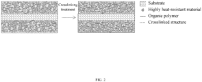
- the photoinitiator in the coating slurry can transition from a ground state to an excited state and capture an H ion from a C-H structure in an organic matter in the coating slurry to produce organic macromolecular free radicals, and when the organic macromolecular free radicals terminate each other, organic macromolecules are crosslinked to form the microscopic network macromolecular structure shown in the right panel of FIG. 2 .
- the above reaction process is shown in FIG. 1 .
- the above reaction may occur in a porous substrate layer and an organic polymer coating layer simultaneously, but there may be different reaction degrees under different conditions.
- the present disclosure also provides a preparation method of the coated separator, including the following steps:
- the coating slurry includes the organic polymer.
- the present disclosure also provides a preparation method of the coated separator, including the following steps: (1) Preparation of the coating slurry: 0.001 wt% to 5.0 wt% of the photoinitiator, 50 wt% to 95 wt% of the inorganic material, and 0 wt% to 5 wt% of other additives are added to the solvent, and a resulting mixture is thoroughly stirred to obtain the coating slurry.
- the coating slurry can include only the photoinitiator and does not include the organic polymer.
- the present disclosure also provides a preparation method of the coated separator, including the following steps:
- the drying above can be conducted through hot air, IR irradiation, or the like.
- the solvent used in the present disclosure can generally be completely removed through heating to form a coating layer.
- a solvent that has a low boiling point and is incompatible with an organic matter in the coating layer can be used to replace the original solvent to form a coating layer with micropores, and then the solvent is removed from the coating layer through drying.
- the UV light has a wavelength of 210 nm to 420 nm and an intensity of 50 mj/cm 2 or more, and the UV crosslinking is conducted for 0.001 s to 10 s.
- the present disclosure provides a method in which a photoinitiator is added to a coating slurry and a crosslinking reaction is allowed to form a thermosetting network polymer structure to improve a thermomechanical strength and a breakage temperature of a porous substrate.
- a separator product prepared by this method is characterized by thermal mechanical analysis (TMA).
- TMA thermal mechanical analysis
- a breakage temperature of the separator product can be increased by 20°C to 80°C compared with a separator product obtained by a process in which no photoinitiator is added for UV crosslinking, and the separator product is not broken after being placed at 180°C for 30 min.
- a specified crosslinked structure of an organic polymer layer can reduce the swelling of the organic polymer layer soaked in an electrolyte at room temperature (25°C) or a high temperature (60°C) while maintaining sufficient adhesion, which can avoid deformation of the organic polymer layer inside a battery, reduce a porosity of the organic polymer layer, and block a lithium ion transmission path, thereby improving the long-term cycling performance of the battery.
- the UV-crosslinked composite separator had a TMA test result of higher than 180°C.
- the UV-crosslinked composite separator had a TMA test result of higher than 180°C.
- the UV-crosslinked composite separator had a TMA test result of higher than 180°C.
- the UV-crosslinked composite separator had a thermal shrinkage rate of less than 5% at 150°C within 1 h and a TMA test result of higher than 180°C.
- the UV-crosslinked composite separator had a thermal shrinkage rate of less than 5% at 150°C within 1 h and a TMA test result of higher than 180°C.
- Example 5 was different from Example 4 in that: the highly heat-resistant material in the coating slurry was a combination of alumina and nanocellulose, and nanocellulose needles were dispersed in the coating layer and overlapped each other to form a physical interconnected structure, which is combined with the organic chemical crosslinked structure in this example to further enhance the heat resistance and high-temperature fusing resistance of the coating layer.
- the highly heat-resistant material in the coating slurry was a combination of alumina and nanocellulose
- nanocellulose needles were dispersed in the coating layer and overlapped each other to form a physical interconnected structure, which is combined with the organic chemical crosslinked structure in this example to further enhance the heat resistance and high-temperature fusing resistance of the coating layer.
- Comparative Example 1 was different from Example 1 in that the coating layer in Comparative Example 1 did not include a photoinitiator and a crosslinked structure, and thus a TMA test result was not improved.
- Comparative Example 2 was different from Example 4 in that the coating layer in Comparative Example 2 did not include a photoinitiator and a crosslinked structure, and as a result, a TMA test result was not improved and a thermal shrinkage rate at 150°C was disadvantageous.
- Comparative Example 3 was different from Example 4 in that the organic matter in the coating layer of Comparative Example 3 was not completely crosslinked (UV irradiation was insufficient), and the crosslinked 3D network organic molecular structure had an insufficient strength, resulting in disadvantageous 150°C thermal shrinkage and TMA test results.
- Table 1 shows TMA test results of the composite separators prepared in Examples 1 to 5 and Comparative Examples 1 to 3 of the present disclosure.
- the TMA test was conducted with the following parameters: a size of a test sample: length: 8 mm, and width: 4 mm; a test tensile force: 0.01 n; and a heating rate: 5°C/min. It can be seen from the data in this table that breakage temperatures of the samples in Examples 1 to 3 are at least 30°C higher than a breakage temperature of the sample in Comparative Example 1 (no crosslinking curing).
- Thickness of a substrate Thickness of the coating layer of the present disclosure ( ⁇ m) Thickness of another coating layer ( ⁇ m)
- Mass proportion of a crosslinked 3D network structure Heat resistance of a coated separator (150°C 1 h, %) TMA test result of a coated separator (°C) Mass proportion of a crosslinked 3D network structure in an organic polymer (%) Mass proportion of a crosslinked 3D network structure in a coating layer (%) MD TD MD TD
- Example 1 9 1.0-2.0 3 70% 50% 3.1 2.2 234.95 227.22
- Example 2 9 4 - 55% 30% - - 204.23 195.85
- Example 3 9 6 - 60% 25% - - 214.51 220.36
- Example 4 9 3 - 85% 3% 2.4 2 220.9 218.43
- Example 5 9 1.5 - 85% 2.5% 2.2 2.2 230.85 231.4 Comparative Example 1 9 1.0-2.0 3 0% 0% 3.5 2.5 152.18 154.17
Landscapes
- Chemical & Material Sciences (AREA)
- Chemical Kinetics & Catalysis (AREA)
- Electrochemistry (AREA)
- General Chemical & Material Sciences (AREA)
- Engineering & Computer Science (AREA)
- Organic Chemistry (AREA)
- Materials Engineering (AREA)
- Wood Science & Technology (AREA)
- Life Sciences & Earth Sciences (AREA)
- Inorganic Chemistry (AREA)
- Polymers & Plastics (AREA)
- Health & Medical Sciences (AREA)
- Medicinal Chemistry (AREA)
- Manufacturing & Machinery (AREA)
- Ceramic Engineering (AREA)
- Composite Materials (AREA)
- Cell Separators (AREA)
- Laminated Bodies (AREA)
Abstract
Description
- The present disclosure relates to the technical field of battery separators, and in particular to a slurry for coating a battery separator, a separator coated with the slurry, and a preparation method of the separator coated with the slurry.
- A battery separator refers to a membrane material layer between a positive electrode and a negative electrode of a battery. As a very critical component of a battery, a battery separator has a direct impact on the safety and cost of the battery. A main function of a battery separator is to isolate positive and negative electrodes of a battery, such that electrons in the battery cannot freely pass through the battery separator and ions in an electrolyte can freely pass through the battery separator.
- An ionic conduction ability of a battery separator is directly related to the overall performance of a battery. The function of a battery separator to isolate positive and negative electrodes of a battery allows an increase of a current to be limited in the case of overcharging or temperature elevation of the battery, thereby preventing an explosion caused by a short circuit of the battery. In addition, a battery separator has a function of micropore self-closing protection, which plays a role in the safety protection for battery users and devices.
- In consideration of the universality and economy of mass production, polyolefin (PO) polymers with a melting point of 130°C to 160°C are adopted as membrane materials in the existing technical solutions, and separator products prepared with these PO polymers have a breakage temperature of 140°C to 170°C. The existing separator products can fully meet needs when batteries are in normal use. However, when a battery undergoes overcharging, internal and external short circuits, collision, squeezing, or the like, a temperature in the battery may soar rapidly to 150°C or higher, and if a separator melts and ruptures prematurely and cannot prevent the direct contact between positive and negative electrodes of the battery, it will cause the massive accumulation of heat in a short term and the further occurrence of thermal runaway, thereby causing battery fire or even explosion accidents. Therefore, the performance of a separator is very important to the safety of a battery.
- In order to solve the above problems, the existing solution is as follows: during preparation of a membrane, a crosslinking agent (such as an organosilane) is directly mixed with raw materials, and a resulting mixture is extruded at a high temperature to directly allow crosslinking. However, this method has the following disadvantages:
- 1. This method has large processing difficulty and a high production cost.
- 2. In this method, a crosslinking agent can hardly be fully dispersed in a material system and can hardly react completely. Thus, products of this method have low consistency, resulting in difficult large-scale production.
- In order to solve the above problems, the present disclosure provides a coating slurry including a photoinitiator, a coated separator prepared with the coating slurry, and a preparation method of the coated separator.
- Technical solutions of the present disclosure are as follows:
A coating slurry is provided, including an organic polymer, a solvent, and a photoinitiator. - Preferably, the organic polymer is added at an amount of 0.05 wt% to 50 wt%; and the organic polymer is selected from one or more of a polyvinylidene fluoride (PVDF) homopolymer, poly(vinylidene fluoride-co-hexafluoropropylene) (PVDF-HFP), poly(vinylidene fluoride-co-trichloroethylene) (PVDF-TCE), polyacrylonitrile (PAN), polymethacrylate (PMA) or a derivative thereof, polyacrylamide (PAM), a polyimide (PI), polyethylene oxide (PEO), PAN, and cellulose.
- Preferably, the photoinitiator is added at an amount of 0.001 wt% to 5.0 wt%; and the photoinitiator is selected from one or a combination of two or more of azodiisobutyronitrile (AIBN), xanthone (XAN), isopropylthioxanthone (ITX), benzophenone (BP), and benzoyl peroxide (BPO).
- Preferably, the solvent is selected from one or more of N,N-dimethylformamide (DMF), N,N-dimethylacetamide (DMAc), dichloroethane (DCE), trichloroethane (TCE), dichloromethane (DCM), chloroform, dimethyl sulfoxide (DMSO), sulfolane, tetramethylurea (TMU), N-methylpyrrolidone (NMP), acetone, water, trimethyl phosphate (TMP), and triethyl phosphate (TEP).
- Preferably, the coating slurry further includes an inorganic material, where a mass proportion of the inorganic material in the coating slurry is 50 wt% to 95 wt%.
- Preferably, the inorganic material is selected from a ceramic material, a nanowire material, or a nanotube material; the ceramic material may be selected from one or a combination of two or more of Al2O3, SiO2, TiO2, ZrO2, MgO, CaO, AlOOH, and SiC; the nanowire material may be selected from one or more of a carbon nanowire, attapulgite, a silver nanowire, a boron carbide nanowire, nanocellulose, a copper hydroxide nanowire, a silicon monoxide nanowire, and a hydroxyapatite nanowire; and the nanotube material may be selected from one or more of a carbon nanotube (CNT), a silver nanotube, a boron carbide nanotube, a copper hydroxide nanotube, a silicon monoxide nanotube, and a hydroxyapatite nanotube. Preferably, the inorganic material is a highly heat-resistant inorganic material.
- Based on the same inventive concept, the present disclosure also provides a coated separator, including a coating layer formed by the coating slurry described above, where the coating layer includes a three-dimensional (3D) network structure, and a mass of the 3D network structure is 50% or more of a total mass of the organic polymer and is 1.0% or more of a total mass of the coating layer. Based on the same inventive concept, the present disclosure also provides a coated separator, including the coating slurry described above and a substrate, where the coating slurry is coated on at least one surface of the substrate and then irradiated under ultraviolet (UV) light with a set energy and wavelength to allow UV crosslinking to obtain the coated separator.
- Preferably, the substrate is selected from one or more of a PO microporous membrane, a PI microporous membrane, a non-woven membrane, a multi-layer composite membrane, a ceramic-coated membrane, and a polymer-coated membrane.
- Based on the same inventive concept, the present disclosure also provides a preparation method of the coated separator, including the following steps:
- (1) preparation of the coating slurry: adding no more than 50 wt% of the organic polymer, 0.001 wt% to 5.0 wt% of the photoinitiator, 50 wt% to 95 wt% of the inorganic material, and 0 wt% to 5 wt% of other additives to the solvent, and thoroughly stirring a resulting mixture to obtain the coating slurry;
- (2) coating: coating the coating slurry on at least one surface of the substrate to obtain a first coated substrate;
- (3) phase transformation: subjecting the first coated substrate to the phase transformation to obtain a second coated substrate;
- (4) drying: rinsing and drying the second coated substrate obtained in the step (3) to obtain a composite separator; and
- (5) UV crosslinking: irradiating the composite separator under UV light to initiate a crosslinking reaction to obtain a UV-crosslinked composite separator.
- The present disclosure also provides a preparation method of the coated separator, including the following steps:
- (1) preparation of the coating slurry: adding 0.001 wt% to 5.0 wt% of the photoinitiator, 50 wt% to 95 wt% of the inorganic material, and 0 wt% to 5 wt% of other additives to the solvent, and thoroughly stirring a resulting mixture to obtain the coating slurry;
- (2) soaking: soaking the substrate in the coating slurry to obtain a first soaked substrate;
- (3) phase transformation: subjecting the first soaked substrate to the phase transformation to obtain a second soaked substrate;
- (4) drying: rinsing and drying the second soaked substrate obtained in the step (3) to obtain a composite separator; and
- (5) UV crosslinking: irradiating the composite separator under UV light to initiate a crosslinking reaction to obtain a UV-crosslinked composite separator.
- The other additives can be one or more of a dispersing agent, a wetting agent, a thickening agent, and a conductive additive.
- Based on the same inventive concept, the present disclosure also provides a preparation method of the coated separator, including the following steps:
- (1) preparation of the coating slurry: adding 0.001 wt% to 5.0 wt% of the photoinitiator, 50 wt% to 95 wt% of a highly heat-resistant material, and 0 wt% to 5 wt% of other additives to the solvent, and thoroughly stirring a resulting mixture to obtain the coating slurry;
- (2) coating: coating the coating slurry on at least one surface of the substrate to obtain a coated substrate; or soaking: soaking the substrate in the coating slurry to obtain a soaked substrate;
- (3) drying: drying the coated substrate or the soaked substrate obtained in the step (2) to obtain a composite separator; and
- (4) UV crosslinking: irradiating the composite separator under UV light to initiate a crosslinking reaction to obtain a UV-crosslinked composite separator.
- The drying above can be conducted through hot air, infrared (IR) irradiation, or the like.
- Preferably, the UV light has a wavelength of 210 nm to 420 nm and an intensity of 50 mj/cm2 or more, and the UV crosslinking is conducted for 0.001 s to 10 s.
- Compared with the prior art, the present disclosure has the following advantages:
In the present disclosure, through UV crosslinking, crosslinking sites on different organic molecular segments in the coating slurry are activated and interconnected to form a network crosslinked structure, which can successfully improve a breakage temperature of a separator with a simple formula and process and a low cost, thereby greatly improving the safety of a battery. -
-
FIG. 1 is a schematic diagram of a reaction process of UV irradiation during preparation of the coated separator of the present disclosure; -
FIG. 2 is a schematic diagram of a microscopic network macromolecular structure formed by UV irradiation during preparation of the coated separator of the present disclosure; and -
FIG. 3 is a comparison diagram of a separator sample before and after being placed in a 180°C oven for 30 min. - In order to overcome defects such as large processing difficulty, high cost, and low crosslinking consistency of the current membrane crosslinking methods, the present disclosure changes the original solution of mixing a crosslinking agent with raw materials for a membrane, and provides a solution in which a photoinitiator is added to a coating slurry and the coating slurry is coated on a membrane and then irradiated under UV light to allow crosslinking to obtain a crosslinked battery separator, which improves the performance of the battery separator and especially improves a breakage temperature of the battery separator.
- Specifically, the present disclosure provides a coating slurry, including an organic polymer, a solvent, and a photoinitiator.
- The organic polymer is added at an amount of 0.05 wt% to 50 wt%; and the organic polymer can be selected from one or more of a PVDF homopolymer, PVDF-HFP, PVDF-TCE, PAN, PMA or a derivative thereof, PAM, PI, PEO, PAN, and cellulose. The amount of the organic polymer added affects the performance of a battery separator. If the amount of the organic polymer added is too small, it will be impossible to form a coating layer with sufficient adhesion. If the amount of the organic polymer added is too large, a microporous structure of a separator may be blocked, which will affect the internal resistance and cycling performance of a battery. Further preferably, the organic polymer is added at an amount of 3 wt% to 45 wt%.
- For example, the organic polymer is added at an amount of 0.05%, 0.1%, 0.5%, 1%, 3%, 5%, 7%, 9%, 11%, 13%, 15%, 17%, 19%, 21%, 23%, 25%, 27%, 29%, 31%, 33%, 35%, 37%, 39%, 41%, 43%, 45%, 49%, or 50%.
- The photoinitiator is added at an amount of 0.001 wt% to 5.0 wt%; and the photoinitiator can be selected from one or a combination of two or more of AIBN, XAN, ITX, BP, and BPO. The amount of the photoinitiator added is closely related to performance of a separator. If the amount of the photoinitiator added is too small, a degree of crosslinking curing will be insufficient, and the improvement of a breakage temperature may not reach an expected level. If the amount of the photoinitiator added is too large, a large amount of the photoinitiator will remain in a separator, and a cost will be increased. Further preferably, the photoinitiator is added at an amount of 0.01 wt% to 5 wt%.
- For example, the photoinitiator is added at an amount of 0.001%, 0.01%, 0.05%, 0.07%, 0.1%, 0.5%, 0.9%, 1%, 1.3%, 1.7%, 1.9%, 2.1%, 2.5%, 2.9%, 3.1%, 3.5%, 3.9%, 4.1%, 4.5%, 4.9%, 5.1%, 5.5%, 5.9%, 6.3%, 6.7%, 6.9%, 7.3%, 7.7%, 7.9%, 8.3%, 8.7%, 8.9%, 9.1%, 9.5%, 9.7%, or 9.9%.
- The solvent can be selected from one or more of DMF, DMAc, DCE, TCE, DCM, chloroform, DMSO, sulfolane, TMU, NMP, acetone, water, TMP, and TEP.
- Further, the coating slurry can further include an inorganic material, where a mass proportion of the inorganic material in the coating slurry is 50 wt% to 95 wt%.
- The inorganic material may be selected from a ceramic material, a nanowire material, or a nanotube material; the ceramic material may be selected from one or a combination of two or more of Al2O3, SiO2, TiO2, ZrO2, MgO, CaO, AlOOH, and SiC; the nanowire material may be selected from one or more of a carbon nanowire, attapulgite, a silver nanowire, a boron carbide nanowire, nanocellulose, a copper hydroxide nanowire, a silicon monoxide nanowire, and a hydroxyapatite nanowire; and the nanotube material may be selected from one or more of CNT, a silver nanotube, a boron carbide nanotube, a copper hydroxide nanotube, a silicon monoxide nanotube, and a hydroxyapatite nanotube.
- The present disclosure also provides a coated separator, including a coating layer formed by the coating slurry described above, where the coating layer includes a 3D network molecular structure, and a mass of the 3D network molecular structure is 50% or more of a total mass of the organic polymer and is 1.0% or more of a total mass of the coating layer. Linear organic polymer molecular chains in the coating slurry are interconnected through branched chains after coating (or soaking), drying, and crosslinking to form a 3D network structure. In the coating layer, the 3D network crosslinked structure serves as a skeleton to tightly encapsulate an inorganic material distributed in the 3D network crosslinked structure. If the mass of the crosslinked network structure is less than 50% of the total mass of the organic polymer or is less than 1.0% of the total mass of the coating layer, a crosslinking degree will be insufficient, crosslinking sites will not be sufficiently interconnected, and the formed 3D network structure cannot maintain a sufficient strength under a high temperature or an external force.
- Those skilled in the art should know that the linear organic polymer can be dissolved in a good solvent, and the crosslinked 3D network structure can only swell in a good solvent and cannot be dissolved in a good solvent. Therefore, a mass proportion of the 3D network structure can be tested as follows: the coated separator or the coating layer is placed in a volatile good solvent, then a resulting system is subjected to Soxhlet extraction and oven-drying such that the 3D network structure and the inorganic material are left, and a residue is burned with a thermogravimetric analyzer (TGA) or a crucible to left the inorganic material, such that the mass proportion of the 3D network structure can be calculated. Of course, the present disclosure is not limited to the above test method, and those skilled in the art can adopt another test method to determine the mass proportion of the 3D network structure according to actual needs.
- The present disclosure also provides a coated separator, including the coating slurry described above and a substrate, where the coating slurry is coated on at least one surface (which may refer to one or two surfaces) of the substrate and then irradiated under UV light with a set energy and wavelength to allow UV crosslinking to obtain the coated separator.
- The substrate includes, but is not limited to, a PO microporous membrane (such as polyethylene (PE), polypropylene (PP), and polybutylene (PB)), a PI microporous membrane, a non-woven membrane, a multi-layer composite membrane, a ceramic-coated membrane, and a polymer-coated membrane.
- Under the UV irradiation with a set wavelength and energy during the preparation of the coated separator of the present disclosure, the photoinitiator in the coating slurry can transition from a ground state to an excited state and capture an H ion from a C-H structure in an organic matter in the coating slurry to produce organic macromolecular free radicals, and when the organic macromolecular free radicals terminate each other, organic macromolecules are crosslinked to form the microscopic network macromolecular structure shown in the right panel of
FIG. 2 . The above reaction process is shown inFIG. 1 . The above reaction may occur in a porous substrate layer and an organic polymer coating layer simultaneously, but there may be different reaction degrees under different conditions. - The present disclosure also provides a preparation method of the coated separator, including the following steps:
- (1) Preparation of the coating slurry:
No more than 50 wt% of the organic polymer, 0.001 wt% to 5.0 wt% of the photoinitiator, 50 wt% to 95 wt% of the inorganic material, and 0 wt% to 5 wt% of other additives are added to the solvent, and a resulting mixture is thoroughly stirred to obtain the coating slurry. - (2) Coating: The coating slurry is coated on at least one surface of the substrate to obtain a first coated substrate, where the at least one surface refers to one or two surfaces.
- (3) Phase transformation: The first coated substrate is subjected to the phase transformation to obtain a second coated substrate. It can be understood that the phase transformation can be conducted through a soaking and coagulating bath, heating, or the like, and a technical means for the phase transformation is not limited here. Preferably, the phase transformation can be conducted through a soaking and coagulating bath, and the soaking and coagulating bath refers to the use of a non-solvent that has a low boiling point and is incompatible with the organic matter in the coating layer to replace the original solvent to form a coating layer with micropores. The non-solvent can be selected from one or more of pure water, glycerol, ethyl acetate, polyethylene glycol (PEG), polyvinylpyrrolidone (PVP), pure water, acetone (CP), methyl acetate (MAC), formic acid, acetic acid, propionic acid, ethanol (EtOH), methanol, isopropanol (i-PrOH), n-butanol (BtOH), n-octanol (OtOH), dodecanol (DoOH), lithium chloride (LiCl), and lithium perchlorate (LiClO4).
- (4) Drying: The second coated substrate obtained in the step (3) is rinsed and dried to obtain a composite separator.
- (5) UV crosslinking: The composite separator is irradiated under UV light to initiate a crosslinking reaction to obtain a UV-crosslinked composite separator, which is the coated separator.
- When the above slurry coating method is adopted, the coating slurry includes the organic polymer.
- The present disclosure also provides a preparation method of the coated separator, including the following steps: (1) Preparation of the coating slurry: 0.001 wt% to 5.0 wt% of the photoinitiator, 50 wt% to 95 wt% of the inorganic material, and 0 wt% to 5 wt% of other additives are added to the solvent, and a resulting mixture is thoroughly stirred to obtain the coating slurry.
- (2) Soaking: The substrate is soaked in the coating slurry to obtain a first soaked substrate.
- (3) Phase transformation: The first soaked substrate is soaked in a non-solvent to allow the phase transformation to obtain a second coated substrate.
- (4) Drying: The second coated substrate obtained in the step (3) is rinsed and dried to obtain a composite separator.
- (5) UV crosslinking: The composite separator is irradiated under UV light to initiate a crosslinking reaction to obtain a UV-crosslinked composite separator.
- When the above slurry soaking method is adopted, the coating slurry can include only the photoinitiator and does not include the organic polymer.
- The present disclosure also provides a preparation method of the coated separator, including the following steps:
- (1) Preparation of the coating slurry: 0.001 wt% to 5.0 wt% of the photoinitiator, 50 wt% to 95 wt% of a highly heat-resistant material, and 0 wt% to 5 wt% of other additives are added to the solvent, and a resulting mixture is thoroughly stirred to obtain the coating slurry.
- (2) Coating: The coating slurry is coated on at least one surface of the substrate to obtain a coated substrate; or soaking: the substrate is soaked in the coating slurry to obtain a soaked substrate.
- (3) Drying: The coated substrate or the soaked substrate obtained in the step (2) is dried to obtain a composite separator.
- (4) UV crosslinking: The composite separator is irradiated under UV light to initiate a crosslinking reaction to obtain a UV-crosslinked composite separator.
- The drying above can be conducted through hot air, IR irradiation, or the like.
- It can be seen that the solvent used in the present disclosure can generally be completely removed through heating to form a coating layer. However, when some solvents with high boiling points that are difficult to be completely removed through direct heating or require a large energy consumption for removal through heating, a solvent that has a low boiling point and is incompatible with an organic matter in the coating layer can be used to replace the original solvent to form a coating layer with micropores, and then the solvent is removed from the coating layer through drying.
- In some preferred embodiments, the UV light has a wavelength of 210 nm to 420 nm and an intensity of 50 mj/cm2 or more, and the UV crosslinking is conducted for 0.001 s to 10 s.
- The present disclosure provides a method in which a photoinitiator is added to a coating slurry and a crosslinking reaction is allowed to form a thermosetting network polymer structure to improve a thermomechanical strength and a breakage temperature of a porous substrate. A separator product prepared by this method is characterized by thermal mechanical analysis (TMA). A breakage temperature of the separator product can be increased by 20°C to 80°C compared with a separator product obtained by a process in which no photoinitiator is added for UV crosslinking, and the separator product is not broken after being placed at 180°C for 30 min.
- In addition, a specified crosslinked structure of an organic polymer layer can reduce the swelling of the organic polymer layer soaked in an electrolyte at room temperature (25°C) or a high temperature (60°C) while maintaining sufficient adhesion, which can avoid deformation of the organic polymer layer inside a battery, reduce a porosity of the organic polymer layer, and block a lithium ion transmission path, thereby improving the long-term cycling performance of the battery.
-
- (1) Preparation of a coating slurry:
9.2 wt% of PVDF and 0.3 wt% of NMP were added to 90.5 wt% of NMP, and a resulting mixture was thoroughly stirred to obtain the coating slurry. - (2) Coating: The coating slurry was coated on two surfaces of a PE porous substrate coated with a ceramic layer to obtain a first coated substrate. A thickness of the PE porous substrate was 9 µm, a thickness of the ceramic layer was 3 µm, and a thickness of a coating layer formed by the coating slurry on each surface was 0.5 µm to 1.0 µm.
- (3) Phase transformation: The first coated substrate was soaked in water to allow the phase transformation to obtain a second coated substrate.
- (4) Drying: The second coated substrate obtained in the step (3) was rinsed and dried to obtain a composite separator.
- (5) UV crosslinking: The composite separator was irradiated under UV light to initiate a crosslinking reaction to obtain a UV-crosslinked composite separator. The UV light had a wavelength of 250 nm to 390 nm and an intensity of 100 mj/cm2 or more, and the UV crosslinking was conducted for 0.1 s.
- The UV-crosslinked composite separator had a TMA test result of higher than 180°C.
-
- (1) Preparation of a coating slurry:
7.5 wt% of PI, 7.5 wt% of PVDF, and 0.5 wt% of BP were added to 84.5 wt% of acetone, and a resulting mixture was thoroughly stirred to obtain the coating slurry. - (2) Coating: The coating slurry was coated on two surfaces of a PE porous substrate coated with a ceramic layer to obtain a coated substrate. A thickness of the PE porous substrate was 9 µm, and a thickness of a coating layer formed by the coating slurry on each surface was 2 µm.
- (3) Drying: The coated substrate obtained in the step (3) was dried to obtain a composite separator.
- (4) UV crosslinking: The composite separator was irradiated under UV light to initiate a crosslinking reaction to obtain a UV-crosslinked composite separator. The UV light had a wavelength of 250 nm to 390 nm and an intensity of 100 mj/cm2 or more, and the UV crosslinking was conducted for 0.5 s.
- The UV-crosslinked composite separator had a TMA test result of higher than 180°C.
-
- (1) Preparation of a coating slurry:
15 wt% of PVDF, 20 wt% of alumina, 5 wt% of nanocellulose, and 0.3 wt% of BP were added to 59.7 wt% of NMP, and a resulting mixture was thoroughly stirred to obtain the coating slurry. - (2) Coating: The coating slurry was coated on two surfaces of a PE porous substrate to obtain a first coated substrate. A thickness of the PE porous substrate was 9 µm, and a thickness of a coating layer formed by the coating slurry on each surface was 3 µm.
- (3) Phase transformation: The first coated substrate was soaked in water to allow the phase transformation to obtain a second coated substrate.
- (4) Drying: The second coated substrate obtained in the step (3) was dried to obtain a composite separator.
- (5) UV crosslinking: The composite separator was irradiated under UV light to initiate a crosslinking reaction to obtain a UV-crosslinked composite separator. The UV light had a wavelength of 240 nm to 380 nm and an intensity of 150 mj/cm2 or more, and the UV crosslinking was conducted for 0.8 s.
- The UV-crosslinked composite separator had a TMA test result of higher than 180°C.
-
- (1) Preparation of a coating slurry:
3.5 wt% of PMA, 35 wt% of alumina, 0.5 wt% of BP, and 1 wt% of other additives were added to 60 wt% of water, and a resulting mixture was thoroughly stirred to obtain the coating slurry. - (2) Coating: The coating slurry was coated on a surface of a PE porous substrate to obtain a coated substrate. A thickness of the PE porous substrate was 9 µm, and a thickness of a coating layer formed by the coating slurry was 3 µm.
- (3) Drying: The coated substrate obtained in the step (2) was dried by hot air or IR rays to remove the solvent in the coating layer to obtain a composite separator.
- (4) UV crosslinking: The composite separator was irradiated under UV light to initiate a crosslinking reaction to obtain a UV-crosslinked composite separator. The UV light had a wavelength of 240 nm to 380 nm and an intensity of 150 mj/cm2 or more, and the UV crosslinking was conducted for 0.8 s.
- The UV-crosslinked composite separator had a thermal shrinkage rate of less than 5% at 150°C within 1 h and a TMA test result of higher than 180°C.
-
- (1) Preparation of a coating slurry:
3.5 wt% of PMA, 30 wt% of alumina, 5 wt% of nanocellulose, 0.5 wt% of BP, and 1 wt% of other additives were added to 60 wt% of water, and a resulting mixture was thoroughly stirred to obtain the coating slurry. - (2) Coating: The coating slurry was coated on a surface of a PE porous substrate to obtain a coated substrate. A thickness of the PE porous substrate was 9 µm, and a thickness of a coating layer formed by the coating slurry was 1.5 µm.
- (3) Drying: The coated substrate obtained in the step (2) was dried by hot air or IR rays to remove the solvent in the coating layer to obtain a composite separator.
- (4) UV crosslinking: The composite separator was irradiated under UV light to initiate a crosslinking reaction to obtain a UV-crosslinked composite separator. The UV light had a wavelength of 240 nm to 380 nm and an intensity of 150 mj/cm2 or more, and the UV crosslinking was conducted for 0.8 s.
- The UV-crosslinked composite separator had a thermal shrinkage rate of less than 5% at 150°C within 1 h and a TMA test result of higher than 180°C.
- Example 5 was different from Example 4 in that: the highly heat-resistant material in the coating slurry was a combination of alumina and nanocellulose, and nanocellulose needles were dispersed in the coating layer and overlapped each other to form a physical interconnected structure, which is combined with the organic chemical crosslinked structure in this example to further enhance the heat resistance and high-temperature fusing resistance of the coating layer.
-
- (1) Preparation of a coating slurry:
9.5 wt% of PVDF was added to 90.5 wt% of NMP, and a resulting mixture was thoroughly stirred to obtain the coating slurry. - (2) Coating: The coating slurry was coated on two surfaces of a PE porous substrate coated with a ceramic layer to obtain a first coated substrate. A thickness of the PE porous substrate was 9 µm, a thickness of the ceramic layer was 3 µm, and a thickness of a coating layer formed by the coating slurry on each surface was 0.5 µm to 1.0 µm.
- (3) Phase transformation: The first coated substrate was soaked in water to allow the phase transformation to obtain a second coated substrate.
- (4) Drying: The second coated substrate obtained in the step (3) was rinsed and dried to obtain a composite separator.
- Comparative Example 1 was different from Example 1 in that the coating layer in Comparative Example 1 did not include a photoinitiator and a crosslinked structure, and thus a TMA test result was not improved.
-
- (1) Preparation of a coating slurry:
4 wt% of PMA, 35 wt% of alumina, and 1 wt% of other additives were added to 60 wt% of water, and a resulting mixture was thoroughly stirred to obtain the coating slurry. - (2) Coating: The coating slurry was coated on a surface of a PE porous substrate to obtain a coated substrate. A thickness of the PE porous substrate was 9 µm, and a thickness of a coating layer formed by the coating slurry was 3 µm.
- (3) Drying: The coated substrate obtained in the step (2) was dried to obtain a composite separator.
- Comparative Example 2 was different from Example 4 in that the coating layer in Comparative Example 2 did not include a photoinitiator and a crosslinked structure, and as a result, a TMA test result was not improved and a thermal shrinkage rate at 150°C was disadvantageous.
-
- (1) Preparation of a coating slurry:
3.5 wt% of PMA, 35 wt% of alumina, 0.5 wt% of BP, and 1 wt% of other additives were added to 60 wt% of water, and a resulting mixture was thoroughly stirred to obtain the coating slurry. - (2) Coating: The coating slurry was coated on a surface of a PE porous substrate to obtain a coated substrate. A thickness of the PE porous substrate was 9 µm, and a thickness of a coating layer formed by the coating slurry was 3 µm.
- (3) Drying: The coated substrate obtained in the step (2) was dried by hot air or IR rays to remove the solvent in the coating layer to obtain a composite separator.
- (4) UV crosslinking: The composite separator was irradiated under UV light to initiate a crosslinking reaction to obtain a UV-crosslinked composite separator. The UV light had a wavelength of 240 nm to 380 nm and an intensity of 100 mj/cm2, and the UV crosslinking was conducted for 0.5 s.
- Comparative Example 3 was different from Example 4 in that the organic matter in the coating layer of Comparative Example 3 was not completely crosslinked (UV irradiation was insufficient), and the crosslinked 3D network organic molecular structure had an insufficient strength, resulting in disadvantageous 150°C thermal shrinkage and TMA test results.
- The prepared composite separators each were subjected to a TMA test, and test results were shown in Table 1. Table 1 shows TMA test results of the composite separators prepared in Examples 1 to 5 and Comparative Examples 1 to 3 of the present disclosure. The TMA test was conducted with the following parameters: a size of a test sample: length: 8 mm, and width: 4 mm; a test tensile force: 0.01 n; and a heating rate: 5°C/min. It can be seen from the data in this table that breakage temperatures of the samples in Examples 1 to 3 are at least 30°C higher than a breakage temperature of the sample in Comparative Example 1 (no crosslinking curing).
Table 1 No. Thickness of a substrate (µm) Thickness of the coating layer of the present disclosure (µm) Thickness of another coating layer (µm) Mass proportion of a crosslinked 3D network structure Heat resistance of a coated separator (150°C 1 h, %) TMA test result of a coated separator (°C) Mass proportion of a crosslinked 3D network structure in an organic polymer (%) Mass proportion of a crosslinked 3D network structure in a coating layer (%) MD TD MD TD Example 1 9 1.0-2.0 3 70% 50% 3.1 2.2 234.95 227.22 Example 2 9 4 - 55% 30% - - 204.23 195.85 Example 3 9 6 - 60% 25% - - 214.51 220.36 Example 4 9 3 - 85% 3% 2.4 2 220.9 218.43 Example 5 9 1.5 - 85% 2.5% 2.2 2.2 230.85 231.4 Comparative Example 1 9 1.0-2.0 3 0% 0% 3.5 2.5 152.18 154.17 Comparative Example 2 9 3 - 0% 0% 4.0 3.8 155.48 152.76 Comparative Example 3 9 3 - 35% 0.8% 23.4 20.7 161.6 152.89 - The technical solutions of the present disclosure have the following characteristics:
- 1. In the present disclosure, a photoinitiator is introduced into a coating slurry for a lithium-ion battery (LIB) separator, and a membrane coated with the coating slurry is irradiated under UV light with a set wavelength and energy to produce a crosslinked structure, thereby improving a thermomechanical strength and a breakage temperature of the separator (membrane).
- 2. A crosslinking degree of an organic polymer coating layer can be controlled to improve the hardness and solvent resistance of the coating layer and reduce the swelling of the coating layer in an electrolyte at room temperature and a high temperature, thereby improving the long-term cycling performance of a battery. A process of organic polymer crosslinking can be controlled by adjusting an amount of a photoinitiator added, selecting a UV crosslinking speed, and setting an irradiation light intensity.
- 3. In the present disclosure, the thermomechanical strength/breakage temperature and adhesion of a separator can be optimally balanced by adjusting a content of a photoinitiator, an intensity and wavelength of UV irradiation, and a UV crosslinking speed. A UV reaction efficiency is allowed to match with a production speed of products during the current mass production to minimize a production cost of a UV crosslinking process and improve an added value of a product. 4. In the technical solution of the present disclosure, only a photoinitiator needs to be added to induce the crosslinking of an organic matter in a conventional polymer-coated separator without requiring an additional crosslinking agent or a crosslinking monomer or a light-cured resin, which involves a simple formula and a low cost and can lead to a product with excellent performance.
- 5. In the current method, an initiator is directly added during preparation of a separator. However, in the method of the present disclosure, a photoinitiator is added to a coating slurry, and the coating slurry is coated on a surface of a membrane and then treated under photoinition conditions to allow crosslinking. The method of the present disclosure is simple and controllable, and can lead to a product meeting a breakage temperature requirement with a low production cost. In addition, the method of the present disclosure solves the problem of additive precipitation caused by incompatibility between an initiator and a substrate, and improves the consistency of appearance and performance of products.
- 6. Compared with the existing unilaterally-stretched separator product, the crosslinked separator product of the present disclosure exhibits effectively-improved tearing resistance.
- The above are merely exemplary embodiments of the present disclosure. A person skilled in the art can also provide a variety of transformation solutions under the teaching of the solutions of the present disclosure, and these transformation solutions all are within the protection scope of the present disclosure.
Claims (13)
- A coating slurry, comprising an organic polymer, a solvent, and a photoinitiator.
- The coating slurry according to claim 1, wherein the organic polymer is added at an amount of 0.05 wt% to 50 wt%; and the organic polymer is selected from one or more of a polyvinylidene fluoride (PVDF) homopolymer, poly(vinylidene fluoride-co-hexafluoropropylene) (PVDF-HFP), poly(vinylidene fluoride-co-trichloroethylene) (PVDF-TCE), polyacrylonitrile (PAN), polymethacrylate (PMA) or a derivative thereof, polyacrylamide (PAM), a polyimide (PI), polyethylene oxide (PEO), PAN, and cellulose.
- The coating slurry according to claim 1 or 2, wherein the photoinitiator is added at an amount of 0.001 wt% to 10 wt%; and the photoinitiator is selected from one or a combination of two or more of azodiisobutyronitrile (AIBN), xanthone (XAN), isopropylthioxanthone (ITX), benzophenone (BP), and benzoyl peroxide (BPO).
- The coating slurry according to claim 1, wherein the solvent is selected from one or more of N,N-dimethylformamide (DMF), N,N-dimethylacetamide (DMAc), dichloroethane (DCE), trichloroethane (TCE), dichloromethane (DCM), chloroform, dimethyl sulfoxide (DMSO), sulfolane, tetramethylurea (TMU), N-methylpyrrolidone (NMP), acetone, water, trimethyl phosphate (TMP), or triethyl phosphate (TEP).
- The coating slurry according to claim 1, further comprising an inorganic material, wherein a mass proportion of the inorganic material in the coating slurry is 0 wt% to 95 wt%.
- The coating slurry according to claim 5, wherein the inorganic material is selected from a ceramic material, a nanowire material, or a nanotube material; the ceramic material is selected from one or a combination of two or more of Al2O3, SiO2, TiO2, ZrO2, MgO, CaO, AlOOH, and SiC; the nanowire material is selected from one or more of a carbon nanowire, attapulgite, a silver nanowire, a boron carbide nanowire, nanocellulose, a copper hydroxide nanowire, a silicon monoxide nanowire, and a hydroxyapatite nanowire; and the nanotube material is selected from one or more of a carbon nanotube (CNT), a silver nanotube, a boron carbide nanotube, a copper hydroxide nanotube, a silicon monoxide nanotube, and a hydroxyapatite nanotube.
- A coated separator, comprising a coating layer formed by the coating slurry according to any one of claims 1 to 6, wherein the coating layer comprises a three-dimensional (3D) network structure formed through interconnection of organic polymer molecules, and a mass of the 3D network structure is 50% or more of a total mass of the organic polymer and is 1.0% or more of a total mass of the coating layer.
- A coated separator, comprising the coating slurry according to any one of claims 1 to 6 and a substrate, wherein the coating slurry is coated on at least one surface of the substrate and then irradiated under ultraviolet (UV) light with a set energy and wavelength to allow UV crosslinking to obtain the coated separator.
- The coated separator according to claim 8, wherein the substrate is selected from one or more of a polyolefin (PO) microporous membrane, a PI microporous membrane, a non-woven membrane, a multi-layer composite membrane, a ceramic-coated membrane, and a polymer-coated membrane.
- A preparation method of the coated separator according to any one of claims 7 to 9, comprising the following steps:(1) preparation of the coating slurry: adding no more than 50 wt% of the organic polymer, 0.001 wt% to 5.0 wt% of the photoinitiator, 50 wt% to 95 wt% of the inorganic material, and 0 wt% to 5 wt% of other additives to the solvent, and thoroughly stirring a resulting mixture to obtain the coating slurry;(2) coating: coating the coating slurry on at least one surface of the substrate to obtain a first coated substrate;(3) phase transformation: subjecting the first coated substrate to the phase transformation to obtain a second coated substrate;(4) drying: rinsing and drying the second coated substrate obtained in the step (3) to obtain a composite separator; and(5) UV crosslinking: irradiating the composite separator under UV light to initiate a crosslinking reaction to obtain a UV-crosslinked composite separator.
- A preparation method of the coated separator according to any one of claims 7 to 9, comprising the following steps:(1) preparation of the coating slurry: adding 0.001 wt% to 5.0 wt% of the photoinitiator, 50 wt% to 95 wt% of a highly heat-resistant material, and 0 wt% to 5 wt% of other additives to the solvent, and thoroughly stirring a resulting mixture to obtain the coating slurry;(2) soaking: soaking the substrate in the coating slurry to obtain a first soaked substrate;(3) phase transformation: subjecting the first soaked substrate to the phase transformation to obtain a second soaked substrate;(4) drying: rinsing and drying the second soaked substrate obtained in the step (3) to obtain a composite separator; and(4) UV crosslinking: irradiating the composite separator under UV light to initiate a crosslinking reaction to obtain a UV-crosslinked composite separator.
- A preparation method of the coated separator according to any one of claims 7 to 9, comprising the following steps:(1) preparation of the coating slurry: adding 0.001 wt% to 5.0 wt% of the photoinitiator, 50 wt% to 95 wt% of a highly heat-resistant material, and 0 wt% to 5 wt% of other additives to the solvent, and thoroughly stirring a resulting mixture to obtain the coating slurry;(2) coating: coating the coating slurry on at least one surface of the substrate to obtain a coated substrate; or soaking: soaking the substrate in the coating slurry to obtain a soaked substrate;(3) drying: drying the coated substrate or the soaked substrate obtained in the step (2) to obtain a composite separator; and(4) UV crosslinking: irradiating the composite separator under UV light to initiate a crosslinking reaction to obtain a UV-crosslinked composite separator.
- The preparation method of the coated separator according to any one of claims 9 to 12, wherein the UV light has a wavelength of 210 nm to 420 nm and an intensity of 50 mj/cm2 or more, and the UV crosslinking is conducted for 0.001 s to 10 s.
Applications Claiming Priority (2)
| Application Number | Priority Date | Filing Date | Title |
|---|---|---|---|
| CN202110665849.0A CN115477876A (en) | 2021-06-16 | 2021-06-16 | Coating slurry, coating diaphragm and preparation method of coating diaphragm |
| PCT/CN2022/098973 WO2022262778A1 (en) | 2021-06-16 | 2022-06-15 | Coating slurry, coated separator and preparation method therefor |
Publications (2)
| Publication Number | Publication Date |
|---|---|
| EP4345141A1 true EP4345141A1 (en) | 2024-04-03 |
| EP4345141A4 EP4345141A4 (en) | 2024-11-20 |
Family
ID=84420279
Family Applications (2)
| Application Number | Title | Priority Date | Filing Date |
|---|---|---|---|
| EP22824036.2A Active EP4346000B1 (en) | 2021-06-16 | 2022-05-27 | Coating liquid, coated separator, separator preparation method, and battery |
| EP22824253.3A Pending EP4345141A4 (en) | 2021-06-16 | 2022-06-15 | Coating slurry, coated separator and preparation method therefor |
Family Applications Before (1)
| Application Number | Title | Priority Date | Filing Date |
|---|---|---|---|
| EP22824036.2A Active EP4346000B1 (en) | 2021-06-16 | 2022-05-27 | Coating liquid, coated separator, separator preparation method, and battery |
Country Status (8)
| Country | Link |
|---|---|
| US (2) | US20240332730A1 (en) |
| EP (2) | EP4346000B1 (en) |
| JP (2) | JP7700280B2 (en) |
| KR (2) | KR20240010728A (en) |
| CN (2) | CN115477876A (en) |
| DK (1) | DK4346000T3 (en) |
| FI (1) | FI4346000T3 (en) |
| WO (2) | WO2022262556A1 (en) |
Families Citing this family (4)
| Publication number | Priority date | Publication date | Assignee | Title |
|---|---|---|---|---|
| CN116283346B (en) * | 2023-03-20 | 2024-07-23 | 江苏厚生新能源科技有限公司 | Lithium ion battery ceramic coating slurry, coating diaphragm and preparation method thereof |
| CN118173656B (en) * | 2024-03-21 | 2025-07-04 | 天合光能股份有限公司 | Preparation method of photovoltaic backboard and photovoltaic backboard |
| CN119297531B (en) * | 2024-09-14 | 2026-01-13 | 河北金力新能源科技股份有限公司 | Battery diaphragm and preparation method thereof |
| WO2026071827A1 (en) * | 2024-09-30 | 2026-04-02 | 주식회사 엘지에너지솔루션 | Separator for electrochemical device, method for manufacturing same, and electrochemical device comprising same |
Family Cites Families (32)
| Publication number | Priority date | Publication date | Assignee | Title |
|---|---|---|---|---|
| JPH1180395A (en) * | 1997-09-09 | 1999-03-26 | Nitto Denko Corp | Porous membrane and separator for non-aqueous electrolyte battery |
| KR101002161B1 (en) * | 2007-11-29 | 2010-12-17 | 주식회사 엘지화학 | Separator with a porous coating layer, a manufacturing method and an electrochemical device having the same |
| JP2013069495A (en) * | 2011-09-21 | 2013-04-18 | Hitachi Ltd | Electrode for nonaqueous electrolyte secondary battery and nonaqueous electrolyte secondary battery, and method of manufacturing electrode for nonaqueous electrolyte secondary battery |
| CN104011925A (en) * | 2011-12-27 | 2014-08-27 | 株式会社Lg化学 | Lithium secondary battery and preparation method thereof |
| CN104078633B (en) * | 2013-03-28 | 2016-08-10 | 比亚迪股份有限公司 | A kind of barrier film, its preparation method and a kind of lithium ion battery |
| KR101618681B1 (en) * | 2014-12-30 | 2016-05-11 | 삼성에스디아이 주식회사 | Composition for forming porous heat-resistance layer, separators comprising the porous heat-resistance layer, electrochemical battery using the separator, and method for preparing the separator |
| CN104835931B (en) * | 2015-03-30 | 2017-03-22 | 东华大学 | Nonwoven fabric lithium ion battery composite diaphragm and preparation method thereof |
| CN104893541A (en) * | 2015-04-14 | 2015-09-09 | 上海大学 | Hydrophilic group-containing UV cured organic/inorganic hybrid lithium ion battery diaphragm coating material |
| WO2017047576A1 (en) * | 2015-09-16 | 2017-03-23 | 日立マクセル株式会社 | Separator for electrochemical elements, method for producing same, and method for manufacturing electrochemical element |
| JP6691856B2 (en) * | 2016-09-28 | 2020-05-13 | 株式会社エンビジョンAescジャパン | Secondary battery |
| CN106953050B (en) * | 2017-02-13 | 2019-08-06 | 河北金力新能源科技股份有限公司 | A kind of high temperature resistance multilayer diaphragm composite lithium ion cell diaphragm and preparation method thereof |
| PL3518318T3 (en) * | 2017-02-13 | 2024-04-15 | Lg Energy Solution, Ltd. | Separation film for lithium secondary battery having adhesive layer |
| CN107134556B (en) * | 2017-03-31 | 2020-05-15 | 乐凯胶片股份有限公司 | A lithium ion battery separator |
| CN107022209A (en) * | 2017-04-24 | 2017-08-08 | 合肥星源新能源材料有限公司 | A kind of lithium ion battery separator coating of high wellability |
| CN107275550B (en) * | 2017-06-20 | 2020-07-07 | 深圳市星源材质科技股份有限公司 | Ceramic and polymer composite coating lithium ion diaphragm and preparation method thereof |
| CN107910476B (en) * | 2017-11-06 | 2021-09-03 | 上海恩捷新材料科技有限公司 | Ceramic composite lithium ion battery diaphragm and preparation method thereof |
| JP7206762B2 (en) * | 2017-12-19 | 2023-01-18 | 株式会社リコー | Electrode and its manufacturing method, electrode element, non-aqueous electrolyte storage element |
| KR102079187B1 (en) * | 2018-03-20 | 2020-02-19 | 주식회사 제라브리드 | Manufacturing method of separator for secondary battery |
| JP2019173227A (en) * | 2018-03-29 | 2019-10-10 | ニッポン高度紙工業株式会社 | Hydrophilic nonwoven fabric and alkaline rechargeable battery |
| CN108586757B (en) * | 2018-04-23 | 2021-02-23 | 东莞市魔方新能源科技有限公司 | Adhesive for battery diaphragm coating and preparation method thereof |
| CN109167005A (en) * | 2018-08-31 | 2019-01-08 | 深圳市星源材质科技股份有限公司 | Composite diaphragm and preparation method thereof |
| CN108847468B (en) * | 2018-09-11 | 2021-05-25 | 江苏清陶能源科技有限公司 | Water-based PVDF-coated lithium ion battery diaphragm and preparation method thereof |
| CN109103397A (en) * | 2018-09-28 | 2018-12-28 | 河南福森新能源科技有限公司 | A kind of preparation method of lithium ion battery ceramic coating membrane |
| CN109524603B (en) * | 2018-11-26 | 2020-08-25 | 深圳市星源材质科技股份有限公司 | Functional diaphragm and preparation method thereof |
| CN109616605B (en) * | 2018-12-27 | 2023-12-26 | 江苏理士电池有限公司 | Lithium ion battery diaphragm and preparation method thereof |
| KR102306446B1 (en) * | 2018-12-28 | 2021-09-28 | 삼성에스디아이 주식회사 | Separator for rechargeable lithium battery and rechargeable lithium battery including the same |
| CN109860486A (en) * | 2018-12-30 | 2019-06-07 | 湖北金泉新材料有限责任公司 | A kind of battery separator and preparation method thereof |
| KR102181119B1 (en) * | 2019-04-26 | 2020-11-23 | 더블유스코프코리아 주식회사 | A crosslinked polyolefin separator and a method for manufacturing the same |
| JP2021057338A (en) * | 2019-09-30 | 2021-04-08 | 東レ株式会社 | Method for manufacturing separator for electrochemical element |
| JP7391201B2 (en) * | 2019-11-08 | 2023-12-04 | エルジー エナジー ソリューション リミテッド | Crosslinked separation membrane for lithium secondary batteries containing crosslinked polyolefin and method for producing the same |
| CN111244374A (en) * | 2019-12-25 | 2020-06-05 | 武汉中兴创新材料技术有限公司 | Coating diaphragm with improved structure and preparation method thereof |
| CN111525080A (en) * | 2020-05-26 | 2020-08-11 | 华鼎国联四川动力电池有限公司 | Preparation method of diaphragm with high porosity and safety performance |
-
2021
- 2021-06-16 CN CN202110665849.0A patent/CN115477876A/en active Pending
-
2022
- 2022-05-27 DK DK22824036.2T patent/DK4346000T3/en active
- 2022-05-27 KR KR1020237044147A patent/KR20240010728A/en active Pending
- 2022-05-27 JP JP2023577864A patent/JP7700280B2/en active Active
- 2022-05-27 US US18/570,655 patent/US20240332730A1/en active Pending
- 2022-05-27 WO PCT/CN2022/095781 patent/WO2022262556A1/en not_active Ceased
- 2022-05-27 EP EP22824036.2A patent/EP4346000B1/en active Active
- 2022-05-27 CN CN202280040428.1A patent/CN117916939A/en active Pending
- 2022-05-27 FI FIEP22824036.2T patent/FI4346000T3/en active
- 2022-06-15 WO PCT/CN2022/098973 patent/WO2022262778A1/en not_active Ceased
- 2022-06-15 KR KR1020237044173A patent/KR20240010729A/en active Pending
- 2022-06-15 JP JP2023577363A patent/JP2024526091A/en active Pending
- 2022-06-15 US US18/570,638 patent/US20240283087A1/en active Pending
- 2022-06-15 EP EP22824253.3A patent/EP4345141A4/en active Pending
Also Published As
| Publication number | Publication date |
|---|---|
| WO2022262778A1 (en) | 2022-12-22 |
| CN117916939A (en) | 2024-04-19 |
| FI4346000T3 (en) | 2026-03-25 |
| EP4346000A4 (en) | 2024-10-30 |
| DK4346000T3 (en) | 2026-03-23 |
| KR20240010729A (en) | 2024-01-24 |
| KR20240010728A (en) | 2024-01-24 |
| US20240332730A1 (en) | 2024-10-03 |
| WO2022262556A1 (en) | 2022-12-22 |
| JP2024526091A (en) | 2024-07-17 |
| EP4346000B1 (en) | 2026-02-11 |
| US20240283087A1 (en) | 2024-08-22 |
| JP7700280B2 (en) | 2025-06-30 |
| JP2024524134A (en) | 2024-07-05 |
| CN115477876A (en) | 2022-12-16 |
| EP4345141A4 (en) | 2024-11-20 |
| EP4346000A1 (en) | 2024-04-03 |
Similar Documents
| Publication | Publication Date | Title |
|---|---|---|
| EP4345141A1 (en) | Coating slurry, coated separator and preparation method therefor | |
| KR101330675B1 (en) | Coating separator film for secondary battery and its preparing method | |
| EP3447822B1 (en) | Composite separator containing aromatic polyamide and manufacturing method thereof, and secondary battery | |
| CN107195838B (en) | Heat-resistant coating with uniform and ordered pore diameter for lithium ion battery diaphragm and preparation method thereof | |
| KR100696144B1 (en) | Microporous film | |
| JP2011516684A (en) | Method for producing polyolefin composite microporous membrane having high heat resistant coating layer | |
| CN110372962B (en) | Cross-linked POSS/PP composite diaphragm, preparation method and application | |
| CN102779965A (en) | Lithium ion battery diaphragm with hydrophilic cross-linking surface layer and manufacture method of lithium ion battery diaphragm | |
| CN111668428B (en) | Method for manufacturing polyolefin separator and electrochemical cell | |
| CN103456908A (en) | High security diaphragm and high capacity lithium ion power battery using high security diaphragm | |
| JPWO2001016219A1 (en) | Microporous film | |
| CN113611983A (en) | Composite diaphragm slurry, preparation method thereof and battery diaphragm | |
| CN110429231A (en) | Cross-linked graphene oxide/polypropylene composite separator, preparation method and application | |
| KR102544964B1 (en) | A separator and a method for manufacturing the same | |
| JP7734785B2 (en) | Cross-linked resin dispersion separator | |
| CN118667480B (en) | High-strength high-elongation conductive glue and preparation method thereof | |
| KR102515272B1 (en) | A method for manufacturing a separator | |
| CN112831130A (en) | Poly 4-methyl-1-pentene microporous membrane and preparation method thereof | |
| KR100506159B1 (en) | Microporous Polyethylene film for battery separator and Method of preparing the same | |
| JP7160621B2 (en) | Trace metal cross-linked separator | |
| KR20230078932A (en) | A separator and a method for manufacturing the same | |
| JP2021036514A (en) | Separator arranged by use of silane crosslinked polyolefin mixed resin | |
| KR102385068B1 (en) | A separator coated with inorganic materials and a method for manufacturing the same | |
| CN121035525A (en) | A composite fiber separator, its preparation method and application, and lithium-ion batteries | |
| CN119542676A (en) | A porous polymer composite diaphragm and preparation method thereof |
Legal Events
| Date | Code | Title | Description |
|---|---|---|---|
| STAA | Information on the status of an ep patent application or granted ep patent |
Free format text: STATUS: THE INTERNATIONAL PUBLICATION HAS BEEN MADE |
|
| PUAI | Public reference made under article 153(3) epc to a published international application that has entered the european phase |
Free format text: ORIGINAL CODE: 0009012 |
|
| STAA | Information on the status of an ep patent application or granted ep patent |
Free format text: STATUS: REQUEST FOR EXAMINATION WAS MADE |
|
| 17P | Request for examination filed |
Effective date: 20231226 |
|
| AK | Designated contracting states |
Kind code of ref document: A1 Designated state(s): AL AT BE BG CH CY CZ DE DK EE ES FI FR GB GR HR HU IE IS IT LI LT LU LV MC MK MT NL NO PL PT RO RS SE SI SK SM TR |
|
| DAV | Request for validation of the european patent (deleted) | ||
| DAX | Request for extension of the european patent (deleted) | ||
| A4 | Supplementary search report drawn up and despatched |
Effective date: 20241022 |
|
| RIC1 | Information provided on ipc code assigned before grant |
Ipc: H01M 10/0525 20100101ALI20241016BHEP Ipc: H01M 50/489 20210101ALI20241016BHEP Ipc: H01M 50/46 20210101ALI20241016BHEP Ipc: H01M 50/457 20210101ALI20241016BHEP Ipc: H01M 50/451 20210101ALI20241016BHEP Ipc: H01M 50/446 20210101ALI20241016BHEP Ipc: H01M 50/44 20210101ALI20241016BHEP Ipc: H01M 50/434 20210101ALI20241016BHEP Ipc: H01M 50/426 20210101ALI20241016BHEP Ipc: H01M 50/417 20210101ALI20241016BHEP Ipc: C09D 179/08 20060101ALI20241016BHEP Ipc: C09D 7/20 20180101ALI20241016BHEP Ipc: C09D 7/61 20180101ALI20241016BHEP Ipc: H01M 50/414 20210101ALI20241016BHEP Ipc: H01M 50/411 20210101ALI20241016BHEP Ipc: H01M 50/403 20210101ALI20241016BHEP Ipc: C08L 23/06 20060101ALI20241016BHEP Ipc: C08J 9/36 20060101ALI20241016BHEP Ipc: C09D 101/02 20060101ALI20241016BHEP Ipc: C09D 127/16 20060101AFI20241016BHEP |