EP4344995B1 - Luftfahrzeug, das mit einem motor und einem abgaskanal ausgestattet ist, um welchen ein ablauf angeordnet ist - Google Patents
Luftfahrzeug, das mit einem motor und einem abgaskanal ausgestattet ist, um welchen ein ablauf angeordnet ist Download PDFInfo
- Publication number
- EP4344995B1 EP4344995B1 EP23191037.3A EP23191037A EP4344995B1 EP 4344995 B1 EP4344995 B1 EP 4344995B1 EP 23191037 A EP23191037 A EP 23191037A EP 4344995 B1 EP4344995 B1 EP 4344995B1
- Authority
- EP
- European Patent Office
- Prior art keywords
- engine
- exhaust duct
- aircraft
- guide
- engine compartment
- Prior art date
- Legal status (The legal status is an assumption and is not a legal conclusion. Google has not performed a legal analysis and makes no representation as to the accuracy of the status listed.)
- Active
Links
Images

Classifications
-
- B—PERFORMING OPERATIONS; TRANSPORTING
- B64—AIRCRAFT; AVIATION; COSMONAUTICS
- B64C—AEROPLANES; HELICOPTERS
- B64C1/00—Fuselages; Constructional features common to fuselages, wings, stabilising surfaces or the like
- B64C1/14—Windows; Doors; Hatch covers or access panels; Surrounding frame structures; Canopies; Windscreens accessories therefor, e.g. pressure sensors, water deflectors, hinges, seals, handles, latches, windscreen wipers
- B64C1/1407—Doors; surrounding frames
- B64C1/1453—Drain masts
-
- B—PERFORMING OPERATIONS; TRANSPORTING
- B64—AIRCRAFT; AVIATION; COSMONAUTICS
- B64D—EQUIPMENT FOR FITTING IN OR TO AIRCRAFT; FLIGHT SUITS; PARACHUTES; ARRANGEMENT OR MOUNTING OF POWER PLANTS OR PROPULSION TRANSMISSIONS IN AIRCRAFT
- B64D33/00—Arrangement in aircraft of power plant parts or auxiliaries not otherwise provided for
- B64D33/04—Arrangement in aircraft of power plant parts or auxiliaries not otherwise provided for of exhaust outlets or jet pipes
-
- F—MECHANICAL ENGINEERING; LIGHTING; HEATING; WEAPONS; BLASTING
- F01—MACHINES OR ENGINES IN GENERAL; ENGINE PLANTS IN GENERAL; STEAM ENGINES
- F01D—NON-POSITIVE DISPLACEMENT MACHINES OR ENGINES, e.g. STEAM TURBINES
- F01D25/00—Component parts, details, or accessories, not provided for in, or of interest apart from, other groups
- F01D25/30—Exhaust heads, chambers, or the like
-
- F—MECHANICAL ENGINEERING; LIGHTING; HEATING; WEAPONS; BLASTING
- F02—COMBUSTION ENGINES; HOT-GAS OR COMBUSTION-PRODUCT ENGINE PLANTS
- F02C—GAS-TURBINE PLANTS; AIR INTAKES FOR JET-PROPULSION PLANTS; CONTROLLING FUEL SUPPLY IN AIR-BREATHING JET-PROPULSION PLANTS
- F02C7/00—Features, components parts, details or accessories, not provided for in, or of interest apart form groups F02C1/00 - F02C6/00; Air intakes for jet-propulsion plants
- F02C7/24—Heat or noise insulation
- F02C7/25—Fire protection or prevention
-
- B—PERFORMING OPERATIONS; TRANSPORTING
- B64—AIRCRAFT; AVIATION; COSMONAUTICS
- B64D—EQUIPMENT FOR FITTING IN OR TO AIRCRAFT; FLIGHT SUITS; PARACHUTES; ARRANGEMENT OR MOUNTING OF POWER PLANTS OR PROPULSION TRANSMISSIONS IN AIRCRAFT
- B64D45/00—Aircraft indicators or protectors not otherwise provided for
- B64D2045/009—Fire detection or protection; Erosion protection, e.g. from airborne particles
-
- F—MECHANICAL ENGINEERING; LIGHTING; HEATING; WEAPONS; BLASTING
- F01—MACHINES OR ENGINES IN GENERAL; ENGINE PLANTS IN GENERAL; STEAM ENGINES
- F01D—NON-POSITIVE DISPLACEMENT MACHINES OR ENGINES, e.g. STEAM TURBINES
- F01D25/00—Component parts, details, or accessories, not provided for in, or of interest apart from, other groups
- F01D25/32—Collecting of condensation water; Drainage ; Removing solid particles
-
- F—MECHANICAL ENGINEERING; LIGHTING; HEATING; WEAPONS; BLASTING
- F05—INDEXING SCHEMES RELATING TO ENGINES OR PUMPS IN VARIOUS SUBCLASSES OF CLASSES F01-F04
- F05D—INDEXING SCHEME FOR ASPECTS RELATING TO NON-POSITIVE-DISPLACEMENT MACHINES OR ENGINES, GAS-TURBINES OR JET-PROPULSION PLANTS
- F05D2260/00—Function
- F05D2260/60—Fluid transfer
- F05D2260/602—Drainage
-
- F—MECHANICAL ENGINEERING; LIGHTING; HEATING; WEAPONS; BLASTING
- F16—ENGINEERING ELEMENTS AND UNITS; GENERAL MEASURES FOR PRODUCING AND MAINTAINING EFFECTIVE FUNCTIONING OF MACHINES OR INSTALLATIONS; THERMAL INSULATION IN GENERAL
- F16N—LUBRICATING
- F16N31/00—Means for collecting, retaining, or draining-off lubricant in or on machines or apparatus
- F16N31/002—Drain pans
-
- G—PHYSICS
- G10—MUSICAL INSTRUMENTS; ACOUSTICS
- G10K—SOUND-PRODUCING DEVICES; METHODS OR DEVICES FOR PROTECTING AGAINST, OR FOR DAMPING, NOISE OR OTHER ACOUSTIC WAVES IN GENERAL; ACOUSTICS NOT OTHERWISE PROVIDED FOR
- G10K2210/00—Details of active noise control [ANC] covered by G10K11/178 but not provided for in any of its subgroups
- G10K2210/10—Applications
- G10K2210/128—Vehicles
- G10K2210/1281—Aircraft, e.g. spacecraft, airplane or helicopter
Definitions
- the present invention relates to an aircraft provided with an engine and an exhaust duct drained around an ejection nozzle of the engine.
- An aircraft and for example a rotorcraft, may include an engine which expels combustion gases through an exhaust nozzle.
- the engine is usually housed in a compartment of the aircraft called the "engine compartment".
- the engine compartment may be delimited by one or more firewalls and/or at least one cowling.
- the aircraft may then include an exhaust duct open to the engine compartment and to an environment external to the aircraft.
- This exhaust duct locally surrounds the exhaust nozzle.
- This exhaust duct may allow the combustion gases from the exhaust nozzle of an engine to be mixed with fresh air from the engine compartment and/or the gases to be directed to preferential areas.
- unburned fuel may be ejected into the exhaust nozzle. Depending on the aircraft's pitch and/or roll attitude, this unburned fuel may then fall by gravity into the exhaust duct and then into the engine compartment.
- the engine compartment walls may reach relatively high temperatures.
- the presence of fuel on these hot walls and air in the engine compartment can pose a fire hazard.
- an engine compartment may be drained to remove any flammable liquids from the engine compartment.
- the document EP 3 932 801 A1 describes an aircraft equipped with an engine compartment.
- the engine compartment is delimited in particular by a fireproof mechanical floor having a funnel shape.
- This funnel shape converges towards at least one internal collection point.
- Such a collection point may include an orifice opening onto a drainage pipe.
- the document EP 3798113 A1 is removed from the invention by describing an aircraft propulsion system.
- This propulsion system includes a nacelle housing an engine and a drainage system.
- the drainage system includes drainage piping configured to direct liquid leaking from an engine component to a reservoir.
- a source of pressurized liquid is used to pressurize the reservoir and direct the liquid to an outlet piping.
- the turbomachine comprises an exhaust casing between a turbine and an exhaust nozzle of the turbomachine.
- the exhaust casing is surrounded by a nacelle by which the turbomachine is attached to an aircraft.
- the exhaust casing comprises an inner ring and an outer ring connected to each other by a plurality of structural arms.
- the outer ring comprises at least one liquid discharge orifice opening onto a liquid recuperator.
- the present invention therefore aims to propose an innovative aircraft equipped with an engine housed in an engine compartment to prevent fuel from running into the engine compartment in the event of engine start failure.
- the invention relates to an aircraft provided with an engine compartment, said aircraft comprising an engine housed at least partially in the engine compartment, the engine comprising an ejection nozzle for at least ejecting gases, said aircraft comprising an exhaust duct arranged around the ejection nozzle, the exhaust duct having an open end opening onto the engine compartment.
- the aircraft comprises a drainage device comprising a guide for collecting a liquid flowing along the exhaust duct and escaping from the exhaust duct through said end.
- the guide then allows the collection of liquid which may flow into the exhaust pipe towards the engine compartment.
- unburned fuel may be expelled into the exhaust nozzle and may fall into the exhaust duct by gravity.
- This exhaust duct is a secondary nozzle, and should not be confused with a nacelle of an aircraft engine. Therefore, depending on the pitch and/or roll angle of the aircraft, unburned fuel may flow into the engine compartment by sliding by gravity along a peripheral wall of the exhaust duct.
- the guide then collects this unburned fuel as it exits through the end of the exhaust pipe.
- the fuel is thus channeled before trickling down the walls of the engine compartment, or is even evacuated into a predetermined area. This reduces the risk of unburned fuel trickling into the engine compartment.
- the invention can limit the risks of unwanted runoff, in particular following a failure to start the engine, for example in cold weather.
- the invention also proves to be relatively simple and can be easily implemented on an existing aircraft equipped with an exhaust duct around an engine nozzle.
- the aircraft may further include one or more of the following features.
- the guide can be arranged following said end with regard to a liquid flowing from the conduit exhaust to the guide, the guide collecting by gravity the liquid escaping from the exhaust duct through said end for predetermined roll and pitch angles of the aircraft.
- the liquid, and if applicable the fuel flowing along the exhaust pipe, is thus collected before running down the walls of the engine compartment.
- the guide can be located in the engine compartment.
- the guide may have a shape distinct from an annular shape. The guide then does not extend 360 degrees around an axis.
- the guide can be attached to the end or can extend partly under the end, or even can extend partly under the end by being arranged against a wall delimiting the engine compartment and carrying the exhaust duct.
- the guide may comprise a gutter delimiting a collection space, said collection space being configured to collect said liquid.
- the term "gutter” refers to a receptacle capable of collecting the liquid escaping from the exhaust pipe through its end.
- the gutter collects by gravity a liquid trickling on the exhaust duct, to convey it to a predetermined zone, in particular for predetermined aircraft attitude angles.
- the gutter may be attached to the exhaust duct, for example by means of gluing, riveting, screwing and/or welding.
- the gutter may form a single piece with the exhaust duct.
- the gutter may be attached to a wall delimiting the engine compartment, for example by means of gluing, riveting, screwing and/or by welding.
- the drainage device may include at least one evacuation orifice, opening where appropriate onto the collection space, to evacuate the liquid.
- the guide can thus collect the liquid flowing in the exhaust duct towards the engine compartment, then evacuate it into a predetermined non-hazardous zone via at least one evacuation orifice.
- the drain hole may be provided on the gutter.
- the gutter directs by gravity a liquid trickling down the exhaust duct, towards the discharge port, in particular for predetermined aircraft attitude angles.
- the drainage device may include an evacuation pipe, for example rigid and/or opening onto the guide.
- piping refers to equipment that may include one or more pipes.
- rigid means that the discharge pipe cannot be twisted manually.
- the liquid can then be evacuated to a non-hazardous area or even outside the aircraft via at least the evacuation pipe.
- the drainage pipe may be attached to the gutter, or may even carry the gutter.
- the drainage device may include conventional fastening members for immobilizing the drainage piping relative to a structure of the aircraft.
- the exhaust pipe may lead directly to a non-hazardous area or even outside the aircraft.
- the aircraft may include a drainage system for draining the engine compartment, the drain piping may lead to the drainage system.
- the drainage device can thus allow unburned fuel present in the exhaust pipe to be evacuated using the engine compartment drainage system, but without runoff into the engine compartment.
- the discharge pipe may open into the drainage system by being connected to this existing drainage system.
- the discharge pipe may open above an orifice of such an existing drainage system to direct the drained liquid by gravity into the drainage system.
- the invention also relates to a method of protection against a risk of fire of such an aircraft provided with an engine compartment, said aircraft comprising an engine housed at least partially in the engine compartment, the engine comprising an ejection nozzle for at least ejecting gases, said aircraft comprising an exhaust duct arranged around the ejection nozzle, the exhaust duct having an open end opening onto the engine compartment, fuel being expelled by said ejection nozzle into the exhaust duct.
- This process then involves the following steps: movement of the fuel along a peripheral wall of the exhaust duct to a guide through said end, and collects with said guide said fuel.
- the method may include moving the fuel from the guide to an engine compartment drainage system.
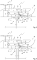
- FIG. 1 presents an example of aircraft 1 according to the invention.
- Such an aircraft 1 comprises a cell 3 in which there is at least one engine compartment 5.
- the engine compartment 5 is delimited by at least one wall 6, 7, 8, and 9.
- the wall(s) 6, 7, 8, and 9 may be fireproof walls, for example fireproof.
- the engine compartment 5 is delimited along a longitudinal axis by at least one wall longitudinal 6, 8.
- the engine compartment 5 is delimited along a transverse axis by at least one transverse wall 7, and vertically at least by a bottom wall 9.
- the aircraft 1 comprises a bottom wall 9 and a transverse wall 7 which extend between two longitudinal walls 6, 8.
- the engine compartment 5 may comprise a standard drainage system 75.
- This drainage system 75 may comprise at least one orifice 90 provided in the bottom wall 9, at least one pipe, at least one inclined plane provided in the bottom wall 9, etc.
- This drainage system 75 has the function of evacuating a liquid to the outside of the engine compartment 5.
- the aircraft 1 further comprises at least one engine 10.
- Such an engine 10 is housed at least partially in the engine compartment 5.
- the engine 10 comprises an engine block 11.
- This engine block 11 may comprise a power shaft 16, connected to a mechanical power transmission chain 4, possibly passing through a longitudinal wall 8.
- This mechanical power transmission chain 4 may set in motion at least one rotor and for example a rotary wing 2.
- the engine 10 may be a heat engine capable of burning fuel to drive the power shaft 16.
- the engine 10 may be a turboshaft engine.
- the engine block 11 may then comprise a gas generator provided with a compressor assembly 12, a combustion chamber 13 and an assembly comprising at least one expansion turbine 14 integral in rotation with the compressor assembly 12.
- the engine 10 may comprise at least one free turbine. 15 following the expansion turbine(s) 14. The free turbine(s) 15 are mechanically linked to the power shaft 16.
- engine 10 may be a piston engine for example.
- this engine 10 comprises an ejection nozzle 20 for at least ejecting gases resulting from the combustion of the fuel.
- the ejection nozzle 20 may extend the engine block.
- the ejection nozzle 20 is located downstream of the free turbine 15 in a direction of circulation of the gases resulting from the combustion of fuel.
- the ejection nozzle 20 passes through a longitudinal wall 6.
- the aircraft 1 is provided with an exhaust duct 30.
- the exhaust duct 30 surrounds the exhaust nozzle 20, namely the entire exhaust nozzle 20 or a portion of the exhaust nozzle 20.
- the exhaust duct 30 is independent of the engine 10 and is located outside the engine 10.
- the exhaust duct 30 may be located outside the engine compartment 5.
- the exhaust duct 30 surrounds at least a portion of the exhaust nozzle 20 located outside the engine compartment 5.
- the exhaust duct 30 extends from an open end 35 opening onto the engine compartment 5 to an open end zone 36. From then on, air present in the compartment 5 can be sucked into the exhaust duct 30.
- the end zone 36 opens onto an environment EXT located outside the aircraft 1.
- the exhaust duct 30 may comprise a peripheral wall 31.
- the peripheral wall 31 delimits an internal volume 33 located inside the exhaust duct 30 and accommodating at least one section of the ejection nozzle 20.
- the peripheral wall 31 extends in thickness from an external face 32 to an internal face 34, this internal face 34 being opposite the ejection nozzle 20.
- the exhaust duct 30 may be a single piece or may comprise several elements fixed to each other.
- the peripheral wall 31 may be a single piece or may comprise several elements fixed to each other.
- the aircraft 1 also comprises a drainage device 40 which has the function of draining a liquid flowing into the exhaust duct 30.
- the drainage device 40 is provided with a guide 45.
- This guide 45 is configured to form a channel and collect a liquid 100 flowing along the internal face 34 of the exhaust duct 30 and escaping therefrom through the end 35.
- the guide 45 may be formed near the end 35.
- the guide 45 may be arranged following the end 35 with regard to the liquid 100 leaving the exhaust duct via this end 35.
- the liquid 100 leaving the end 35 falls by gravity into the guide 45.
- the guide 45 is attached, possibly in a sealed manner, to the end 35 or extends partly under the end 35, for example being arranged against a wall 6 of the engine compartment 5 carrying the exhaust duct 30.
- the guide 45 can then be arranged in the engine compartment 5.
- the guide 45 has, according to the illustrated example, a shape distinct from an annular shape.
- guide 45 has a gutter 50.
- the gutter 50 delimits a harvesting space 55.
- This collection space 55 then makes it possible to collect by gravity a liquid 100 flowing on the internal face 34 of the peripheral wall 31 and flowing through the end 35, for predetermined roll and pitch angles of the aircraft.
- the gutter 50 may rest against the end 35 of the exhaust duct 30, or under the end 35 to collect by gravity the liquid escaping from the exhaust duct by trickling through the end 35.
- the gutter 50 can be fixed to the exhaust duct 30 or to a wall 6 of the engine compartment 30, or can form a single piece with this exhaust duct 30 or this wall 6.
- the guide 45 may be provided with at least one discharge orifice 60 in order to discharge the collected liquid 100.
- a discharge orifice 60 may open onto the collection space 55 so that a liquid collected in the collection space 55 escapes from the collection space 55 through this discharge orifice 60.
- At least one discharge orifice 60 can be provided in the gutter 50.
- the drainage device 40 may be provided with at least one discharge pipe 65 opening into the collection space via a discharge orifice 60.
- At least one drain pipe 65 is fixed to the gutter 50.
- the drain pipe 65 is optionally fixed to a supporting structure of the aircraft, or even to a wall of the engine compartment 5.
- the evacuation pipe 65 can carry the gutter 50.
- At least one evacuation pipe 65 may, if necessary, open into the drainage system 75.
- the discharge pipe 65 can then be hydraulically connected to the drainage system 75.
- the discharge pipe 35 can pass through a wall of the engine compartment, for example the bottom wall 9, to join a pipe of the drainage system.
- the evacuation pipe 65 can open onto an orifice 90 of the drainage system 75.
- the evacuation pipe 65 opens above an orifice 90 provided in a bottom wall 9 of the engine compartment, this orifice 90 being connected to a pipe of the drainage system 75.
- the discharge pipe 65 can open into a predetermined non-risky zone without passing through the drainage system 75.
- a variant may possibly be preferred in order to minimize the total mass of the installation.
- the drainage device 40 may tend to reduce the risks of fire under particular conditions.
- the start of an engine 5 can fail for multiple reasons.
- unburned fuel can be expelled into the ejection nozzle 20 according to arrow F1.
- This unburned fuel can then fall by gravity into the exhaust duct 30 according to arrow F2.
- this unburned fuel can be moved by gravity towards engine compartment 5 according to arrow F3.
- the unburned fuel flows in particular along the peripheral wall 31, and in particular along its internal face 34.
- the guide 45 makes it possible to collect this unburned fuel according to the arrow F4 before the unburned fuel unduly trickles down the walls of the engine compartment 5. If necessary, the unburned fuel is evacuated by gravity via the evacuation pipe(s) 65 and then, according to the variants of the figures 1 And 3 through the drainage system 75 according to arrow F5. The risks of having unburned fuel resting in the bottom of the engine compartment 5 are therefore reduced.
Landscapes
- Engineering & Computer Science (AREA)
- Mechanical Engineering (AREA)
- Chemical & Material Sciences (AREA)
- Combustion & Propulsion (AREA)
- General Engineering & Computer Science (AREA)
- Aviation & Aerospace Engineering (AREA)
- Exhaust Silencers (AREA)
- Health & Medical Sciences (AREA)
- Public Health (AREA)
- Business, Economics & Management (AREA)
- Emergency Management (AREA)
- Chemical Kinetics & Catalysis (AREA)
- General Chemical & Material Sciences (AREA)
- Oil, Petroleum & Natural Gas (AREA)
- Jet Pumps And Other Pumps (AREA)
Claims (16)
- Luftfahrzeug (1) mit einem Triebwerksraum (5), wobei das Luftfahrzeug (1) ein zumindest teilweise im Triebwerksraum (5) untergebrachtes Triebwerk (10) umfasst, und das Triebwerk (10) eine Ausstoßdüse (20) mindestens zum Ausstoßen von Gasen umfasst, wobei das Luftfahrzeug (1) einen um die Ausstoßdüse (20) herum angeordneten Abgaskanal (30) umfasst, und der Abgaskanal (30) ein offenes Ende (35) aufweist, das in den Triebwerksraum (5) mündet,
dadurch gekennzeichnet, dass das Luftfahrzeug (1) eine Drainagevorrichtung (40) aufweist, die eine Führung (45) zum Sammeln einer entlang des Abgaskanals (30) fließenden und aus dem Abgaskanal (30) durch das Ende (35) austretenden Flüssigkeit (100) umfasst, wobei die Drainagevorrichtung (40) mindestens eine Abflussöffnung (60) zum Ableiten der Flüssigkeit (100) aufweist. - Luftfahrzeug nach Anspruch 1,
dadurch gekennzeichnet, dass die Führung (45) in Bezug auf die Flüssigkeit (100), die aus dem Auslasskanal in Richtung der Führung (45) fließt, hinter dem Ende (35) angeordnet ist, wobei die Führung (45) die aus dem Auslasskanal durch das Ende (35) austretende Flüssigkeit (100) unter vorgegebenen Roll- und Nickwinkeln des Luftfahrzeugs (1) durch Schwerkraft auffängt. - Luftfahrzeug nach einem der Ansprüche 1 bis 2,
dadurch gekennzeichnet, dass die Führung (45) im Triebwerksraum angeordnet ist. - Luftfahrzeug nach einem der Ansprüche 1 bis 3,
dadurch gekennzeichnet, dass die Führung (45) eine Rinne (50) umfasst, die einen Auffangraum (55) begrenzt, wobei der Auffangraum (55) zum Auffangen der Flüssigkeit (100) ausgebildet ist. - Luftfahrzeug nach Anspruch 4,
dadurch gekennzeichnet, dass die Rinne (50) an dem Abgaskanal (30) befestigt ist oder einstückig mit dem Abgaskanal (30) ausgebildet ist. - Luftfahrzeug nach einem der Ansprüche 1 bis 5,
dadurch gekennzeichnet, dass die Führung (45) eine Rinne (50) umfasst und die Abflussöffnung (60) an der Rinne (50) ausgebildet ist. - Luftfahrzeug nach einem der Ansprüche 1 bis 6,
dadurch gekennzeichnet, dass die Drainagevorrichtung (40) eine Abflussleitung (65) umfasst. - Luftfahrzeug nach Anspruch 7,
dadurch gekennzeichnet, dass die Führung (45) eine Rinne (50) umfasst und die Abflussleitung (65) an der Rinne (50) befestigt ist. - Luftfahrzeug nach einem der Ansprüche 7 bis 8,
dadurch gekennzeichnet, dass das Luftfahrzeug (1) ein Drainagesystem (75) zum Drainieren des Triebwerksraums (5) umfasst, und die Abflussleitung (65) in das Drainagesystem (75) mündet. - Luftfahrzeug nach einem der Ansprüche 1 bis 9,
dadurch gekennzeichnet, dass der Abgaskanal (30) unabhängig vom Triebwerk (10) ist und außerhalb des Triebwerks (10) angeordnet ist. - Luftfahrzeug nach einem der Ansprüche 1 bis 10,
dadurch gekennzeichnet, dass der Abgaskanal (30) außerhalb des Triebwerksraums (5) angeordnet ist, wobei die Ausstoßdüse (20) eine den Triebwerksraum (5) begrenzende Wand durchdringt. - Luftfahrzeug nach einem der Ansprüche 1 bis 11,
dadurch gekennzeichnet, dass das Triebwerk (10) einen Triebwerksblock umfasst, der durch die Ausstoßdüse (20) verlängert ist. - Luftfahrzeug nach einem der Ansprüche 1 bis 12,
dadurch gekennzeichnet, dass die Führung (45) eine von einer Ringform abweichende Form aufweist. - Luftfahrzeug nach einem der Ansprüche 1 bis 13,
dadurch gekennzeichnet, dass die Führung (45) an das Ende (35) angrenzt oder sich teilweise unter dem Ende (35) erstreckt oder sich teilweise unter dem Ende (35) erstreckt und dabei an einer Wand (6) angeordnet ist, die den Triebwerksraum (5) begrenzt und den Abgaskanal (30) trägt. - Verfahren zum Schutz eines mit einem Triebwerksraum (5) versehenen Luftfahrzeugs (1) vor Brandgefahr, wobei das Luftfahrzeug (1) ein zumindest teilweise im Triebwerksraum (5) untergebrachtes Triebwerk (10) umfasst, wobei das Triebwerk (10) eine Ausstoßdüse (20) zumindest zum Ausstoßen von Gasen umfasst, wobei das Luftfahrzeug (1) einen um die Ausstoßdüse (20) herum angeordneten Abgaskanal (30) umfasst, wobei der Abgaskanal (30) ein offenes Ende (35) aufweist, das in den Triebwerksraum (5) mündet, wobei Kraftstoff durch die Ausstoßdüse (20) in den Abgaskanal (30) ausgestoßen wird,
wobei das Verfahren die folgenden Schritte umfasst: Bewegen (F3) des Kraftstoffs entlang einer Umfangswand (31) des Auslasskanals (30) zu einer Führung (45) durch das Ende (35) hindurch und Sammeln (F4) des Kraftstoffs (100) mit der Führung. - Verfahren nach Anspruch 15,
wobei das Verfahren ein Bewegen des Kraftstoffs (100) von der Führung zu einem Drainagesystem (75) des Triebwerksraums (5) umfasst.
Applications Claiming Priority (1)
| Application Number | Priority Date | Filing Date | Title |
|---|---|---|---|
| FR2209784A FR3140117A1 (fr) | 2022-09-27 | 2022-09-27 | Aéronef muni d’un moteur et d’un conduit d’échappement drainé autour d’une tuyère d’éjection du moteur |
Publications (2)
| Publication Number | Publication Date |
|---|---|
| EP4344995A1 EP4344995A1 (de) | 2024-04-03 |
| EP4344995B1 true EP4344995B1 (de) | 2025-06-04 |
Family
ID=84370865
Family Applications (1)
| Application Number | Title | Priority Date | Filing Date |
|---|---|---|---|
| EP23191037.3A Active EP4344995B1 (de) | 2022-09-27 | 2023-08-11 | Luftfahrzeug, das mit einem motor und einem abgaskanal ausgestattet ist, um welchen ein ablauf angeordnet ist |
Country Status (3)
| Country | Link |
|---|---|
| US (1) | US12595072B2 (de) |
| EP (1) | EP4344995B1 (de) |
| FR (1) | FR3140117A1 (de) |
Families Citing this family (2)
| Publication number | Priority date | Publication date | Assignee | Title |
|---|---|---|---|---|
| FR3143008B1 (fr) * | 2022-12-09 | 2024-11-01 | Airbus Helicopters | Aéronef muni d’un moteur et d’un conduit d’échappement autour d’une tuyère d’éjection du moteur |
| EP4458669B1 (de) * | 2023-05-05 | 2025-07-02 | AIRBUS HELICOPTERS DEUTSCHLAND GmbH | Drehflügelflugzeug mit einer firewall-anordnung mit mindestens einer trichterförmigen unteren firewall |
Family Cites Families (7)
| Publication number | Priority date | Publication date | Assignee | Title |
|---|---|---|---|---|
| US2949736A (en) * | 1952-10-03 | 1960-08-23 | Rolls Royce | Expansion joint with fuel drainage collector for ducting of gas turbine power plants |
| US4163366A (en) * | 1977-05-23 | 1979-08-07 | Avco Corporation | Apparatus for disposal of leaking fluids in a turbofan engine |
| US6109562A (en) * | 1998-04-22 | 2000-08-29 | Pratt & Whitney Canada Corp. | Aircraft construction |
| US8820045B2 (en) * | 2010-07-30 | 2014-09-02 | United Technologies Corporation | Auxiliary power unit fire enclosure drain seal |
| FR3098242B1 (fr) | 2019-07-04 | 2021-06-25 | Safran Aircraft Engines | Ensemble récupérateur de fluide pour turbomachine à gaz |
| EP3798113B1 (de) | 2019-09-30 | 2023-03-29 | Rohr, Inc. | Flüssigkeitsentwässerungssystem für ein flugzeugantriebssystem |
| EP3932801B1 (de) | 2020-06-30 | 2022-05-18 | AIRBUS HELICOPTERS DEUTSCHLAND GmbH | Drehflügel-flugzeug mit einer brandschutzvorrichtung |
-
2022
- 2022-09-27 FR FR2209784A patent/FR3140117A1/fr active Pending
-
2023
- 2023-08-11 EP EP23191037.3A patent/EP4344995B1/de active Active
- 2023-08-15 US US18/233,965 patent/US12595072B2/en active Active
Also Published As
| Publication number | Publication date |
|---|---|
| FR3140117A1 (fr) | 2024-03-29 |
| EP4344995A1 (de) | 2024-04-03 |
| US20240109666A1 (en) | 2024-04-04 |
| US12595072B2 (en) | 2026-04-07 |
Similar Documents
| Publication | Publication Date | Title |
|---|---|---|
| EP4344995B1 (de) | Luftfahrzeug, das mit einem motor und einem abgaskanal ausgestattet ist, um welchen ein ablauf angeordnet ist | |
| EP2085579B1 (de) | Ölabscheidevorrichtung und Turbotriebwerk umfassend diese Vorrichtung | |
| EP4129827B1 (de) | Luftfahrzeug mit mindestens einer vorrichtung zur wasserstoffversorgung sowie mindestens einem dichten behälter, in dem mindestens ein ausrüstungsteil der vorrichtung zur wasserstoffversorgung positioniert ist | |
| EP1965040B1 (de) | Enteisungssystem mittels Öl des Bugkonus eines Flugzeug-Turbostrahltriebwerks | |
| EP1881181B1 (de) | Strömungsmaschine | |
| EP0540406B1 (de) | Hubschraubergetriebe mit einem Schutzsystem im Falle eines Schmierölverlustes | |
| EP3945033B1 (de) | Flugzeugantriebseinheit | |
| EP3701171B1 (de) | Antriebseinheit für ein flugzeug | |
| FR2987402A1 (fr) | Dispositif de lubrification d'un reducteur epicycloidal compatible d'un montage modulaire. | |
| FR2694962A1 (fr) | Turboréacteur dont la chambre de combustion est protégée contre les effets d'une ingestion massive d'eau. | |
| EP1308601A1 (de) | Abblasvorrichtung eines Bläsertriebwerks | |
| FR3075866A1 (fr) | Tube de degazage pour une turbomachine d'aeronef a reducteur | |
| FR3127521A1 (fr) | Carter d’injection d’air de refroidissement pour turbine de turbomachine | |
| WO2015082799A1 (fr) | Ensemble propulsif comportant une boite de retention de fluides draines | |
| BE1025263B1 (fr) | Compresseur degivrant de turbomachine et procede de degivrage | |
| FR3088956A1 (fr) | Systeme de lubrification pour turbomachine d’aeronef, comprenant des moyens ameliores de detection de fuite | |
| EP2643069B1 (de) | Vorrichtung zum ölabführen und turbomaschine mit solcher vorrichtung | |
| EP4515085A1 (de) | Sammler für eine drainierte flüssigkeit für ein flugzeugturbinentriebwerk und zugehöriges turbinentriebwerk | |
| FR3075868B1 (fr) | Tube de degazage pour une turbomachine d'aeronef a reducteur | |
| EP4022176B1 (de) | Turbinenanordnung, die eine umlaufende ölrückgewinnungsrinne enthält | |
| FR3098243A1 (fr) | Ensemble récupérateur de fluide pour turbomachine à gaz | |
| FR3098242A1 (fr) | Ensemble récupérateur de fluide pour turbomachine à gaz | |
| WO2023209284A1 (fr) | Collecteur d'un liquide draine pour turbomachine d'aeronef et turbomachine associee | |
| FR3063345A1 (fr) | Dispositif de test d'une turbomachine a gaz pour aeronef | |
| EP4474288B1 (de) | Flugzeug mit regenschutzentlüftung für eine elektrische maschine |
Legal Events
| Date | Code | Title | Description |
|---|---|---|---|
| PUAI | Public reference made under article 153(3) epc to a published international application that has entered the european phase |
Free format text: ORIGINAL CODE: 0009012 |
|
| STAA | Information on the status of an ep patent application or granted ep patent |
Free format text: STATUS: THE APPLICATION HAS BEEN PUBLISHED |
|
| AK | Designated contracting states |
Kind code of ref document: A1 Designated state(s): AL AT BE BG CH CY CZ DE DK EE ES FI FR GB GR HR HU IE IS IT LI LT LU LV MC ME MK MT NL NO PL PT RO RS SE SI SK SM TR |
|
| STAA | Information on the status of an ep patent application or granted ep patent |
Free format text: STATUS: REQUEST FOR EXAMINATION WAS MADE |
|
| 17P | Request for examination filed |
Effective date: 20240404 |
|
| RBV | Designated contracting states (corrected) |
Designated state(s): AL AT BE BG CH CY CZ DE DK EE ES FI FR GB GR HR HU IE IS IT LI LT LU LV MC ME MK MT NL NO PL PT RO RS SE SI SK SM TR |
|
| P01 | Opt-out of the competence of the unified patent court (upc) registered |
Effective date: 20240404 |
|
| GRAP | Despatch of communication of intention to grant a patent |
Free format text: ORIGINAL CODE: EPIDOSNIGR1 |
|
| STAA | Information on the status of an ep patent application or granted ep patent |
Free format text: STATUS: GRANT OF PATENT IS INTENDED |
|
| RIC1 | Information provided on ipc code assigned before grant |
Ipc: F02C 7/25 20060101ALN20250220BHEP Ipc: B64D 45/00 20060101ALN20250220BHEP Ipc: B64D 29/06 20060101ALN20250220BHEP Ipc: F01D 25/30 20060101ALI20250220BHEP Ipc: F01D 25/32 20060101ALI20250220BHEP Ipc: B64D 33/04 20060101ALI20250220BHEP Ipc: B64C 1/14 20060101AFI20250220BHEP |
|
| INTG | Intention to grant announced |
Effective date: 20250317 |
|
| RIC1 | Information provided on ipc code assigned before grant |
Ipc: F02C 7/25 20060101ALN20250310BHEP Ipc: B64D 45/00 20060101ALN20250310BHEP Ipc: B64D 29/06 20060101ALN20250310BHEP Ipc: F01D 25/30 20060101ALI20250310BHEP Ipc: F01D 25/32 20060101ALI20250310BHEP Ipc: B64D 33/04 20060101ALI20250310BHEP Ipc: B64C 1/14 20060101AFI20250310BHEP |
|
| GRAS | Grant fee paid |
Free format text: ORIGINAL CODE: EPIDOSNIGR3 |
|
| GRAA | (expected) grant |
Free format text: ORIGINAL CODE: 0009210 |
|
| STAA | Information on the status of an ep patent application or granted ep patent |
Free format text: STATUS: THE PATENT HAS BEEN GRANTED |
|
| AK | Designated contracting states |
Kind code of ref document: B1 Designated state(s): AL AT BE BG CH CY CZ DE DK EE ES FI FR GB GR HR HU IE IS IT LI LT LU LV MC ME MK MT NL NO PL PT RO RS SE SI SK SM TR |
|
| REG | Reference to a national code |
Ref country code: GB Ref legal event code: FG4D Free format text: NOT ENGLISH |
|
| REG | Reference to a national code |
Ref country code: CH Ref legal event code: EP |
|
| REG | Reference to a national code |
Ref country code: DE Ref legal event code: R096 Ref document number: 602023003811 Country of ref document: DE |
|
| REG | Reference to a national code |
Ref country code: IE Ref legal event code: FG4D Free format text: LANGUAGE OF EP DOCUMENT: FRENCH |
|
| REG | Reference to a national code |
Ref country code: NL Ref legal event code: MP Effective date: 20250604 |
|
| PG25 | Lapsed in a contracting state [announced via postgrant information from national office to epo] |
Ref country code: ES Free format text: LAPSE BECAUSE OF FAILURE TO SUBMIT A TRANSLATION OF THE DESCRIPTION OR TO PAY THE FEE WITHIN THE PRESCRIBED TIME-LIMIT Effective date: 20250604 Ref country code: FI Free format text: LAPSE BECAUSE OF FAILURE TO SUBMIT A TRANSLATION OF THE DESCRIPTION OR TO PAY THE FEE WITHIN THE PRESCRIBED TIME-LIMIT Effective date: 20250604 |
|
| PGFP | Annual fee paid to national office [announced via postgrant information from national office to epo] |
Ref country code: DE Payment date: 20250820 Year of fee payment: 3 |
|
| REG | Reference to a national code |
Ref country code: LT Ref legal event code: MG9D |
|
| PG25 | Lapsed in a contracting state [announced via postgrant information from national office to epo] |
Ref country code: GR Free format text: LAPSE BECAUSE OF FAILURE TO SUBMIT A TRANSLATION OF THE DESCRIPTION OR TO PAY THE FEE WITHIN THE PRESCRIBED TIME-LIMIT Effective date: 20250905 Ref country code: NO Free format text: LAPSE BECAUSE OF FAILURE TO SUBMIT A TRANSLATION OF THE DESCRIPTION OR TO PAY THE FEE WITHIN THE PRESCRIBED TIME-LIMIT Effective date: 20250904 |
|
| PG25 | Lapsed in a contracting state [announced via postgrant information from national office to epo] |
Ref country code: PL Free format text: LAPSE BECAUSE OF FAILURE TO SUBMIT A TRANSLATION OF THE DESCRIPTION OR TO PAY THE FEE WITHIN THE PRESCRIBED TIME-LIMIT Effective date: 20250604 |
|
| PGFP | Annual fee paid to national office [announced via postgrant information from national office to epo] |
Ref country code: IT Payment date: 20250901 Year of fee payment: 3 |
|
| PG25 | Lapsed in a contracting state [announced via postgrant information from national office to epo] |
Ref country code: BG Free format text: LAPSE BECAUSE OF FAILURE TO SUBMIT A TRANSLATION OF THE DESCRIPTION OR TO PAY THE FEE WITHIN THE PRESCRIBED TIME-LIMIT Effective date: 20250604 |
|
| PG25 | Lapsed in a contracting state [announced via postgrant information from national office to epo] |
Ref country code: HR Free format text: LAPSE BECAUSE OF FAILURE TO SUBMIT A TRANSLATION OF THE DESCRIPTION OR TO PAY THE FEE WITHIN THE PRESCRIBED TIME-LIMIT Effective date: 20250604 |
|
| PGFP | Annual fee paid to national office [announced via postgrant information from national office to epo] |
Ref country code: AT Payment date: 20251020 Year of fee payment: 3 Ref country code: FR Payment date: 20250828 Year of fee payment: 3 |
|
| PG25 | Lapsed in a contracting state [announced via postgrant information from national office to epo] |
Ref country code: RS Free format text: LAPSE BECAUSE OF FAILURE TO SUBMIT A TRANSLATION OF THE DESCRIPTION OR TO PAY THE FEE WITHIN THE PRESCRIBED TIME-LIMIT Effective date: 20250904 |
|
| PG25 | Lapsed in a contracting state [announced via postgrant information from national office to epo] |
Ref country code: LV Free format text: LAPSE BECAUSE OF FAILURE TO SUBMIT A TRANSLATION OF THE DESCRIPTION OR TO PAY THE FEE WITHIN THE PRESCRIBED TIME-LIMIT Effective date: 20250604 |
|
| PG25 | Lapsed in a contracting state [announced via postgrant information from national office to epo] |
Ref country code: NL Free format text: LAPSE BECAUSE OF FAILURE TO SUBMIT A TRANSLATION OF THE DESCRIPTION OR TO PAY THE FEE WITHIN THE PRESCRIBED TIME-LIMIT Effective date: 20250604 |
|
| PG25 | Lapsed in a contracting state [announced via postgrant information from national office to epo] |
Ref country code: PT Free format text: LAPSE BECAUSE OF FAILURE TO SUBMIT A TRANSLATION OF THE DESCRIPTION OR TO PAY THE FEE WITHIN THE PRESCRIBED TIME-LIMIT Effective date: 20251006 |
|
| REG | Reference to a national code |
Ref country code: AT Ref legal event code: MK05 Ref document number: 1800135 Country of ref document: AT Kind code of ref document: T Effective date: 20250604 |
|
| PG25 | Lapsed in a contracting state [announced via postgrant information from national office to epo] |
Ref country code: IS Free format text: LAPSE BECAUSE OF FAILURE TO SUBMIT A TRANSLATION OF THE DESCRIPTION OR TO PAY THE FEE WITHIN THE PRESCRIBED TIME-LIMIT Effective date: 20251004 |
|
| PG25 | Lapsed in a contracting state [announced via postgrant information from national office to epo] |
Ref country code: SM Free format text: LAPSE BECAUSE OF FAILURE TO SUBMIT A TRANSLATION OF THE DESCRIPTION OR TO PAY THE FEE WITHIN THE PRESCRIBED TIME-LIMIT Effective date: 20250604 Ref country code: AT Free format text: LAPSE BECAUSE OF FAILURE TO SUBMIT A TRANSLATION OF THE DESCRIPTION OR TO PAY THE FEE WITHIN THE PRESCRIBED TIME-LIMIT Effective date: 20250604 |
|
| PG25 | Lapsed in a contracting state [announced via postgrant information from national office to epo] |
Ref country code: CZ Free format text: LAPSE BECAUSE OF FAILURE TO SUBMIT A TRANSLATION OF THE DESCRIPTION OR TO PAY THE FEE WITHIN THE PRESCRIBED TIME-LIMIT Effective date: 20250604 |
|
| PG25 | Lapsed in a contracting state [announced via postgrant information from national office to epo] |
Ref country code: EE Free format text: LAPSE BECAUSE OF FAILURE TO SUBMIT A TRANSLATION OF THE DESCRIPTION OR TO PAY THE FEE WITHIN THE PRESCRIBED TIME-LIMIT Effective date: 20250604 |
|
| PG25 | Lapsed in a contracting state [announced via postgrant information from national office to epo] |
Ref country code: SK Free format text: LAPSE BECAUSE OF FAILURE TO SUBMIT A TRANSLATION OF THE DESCRIPTION OR TO PAY THE FEE WITHIN THE PRESCRIBED TIME-LIMIT Effective date: 20250604 |
|
| REG | Reference to a national code |
Ref country code: DE Ref legal event code: R097 Ref document number: 602023003811 Country of ref document: DE |
|
| PG25 | Lapsed in a contracting state [announced via postgrant information from national office to epo] |
Ref country code: RO Free format text: LAPSE BECAUSE OF FAILURE TO SUBMIT A TRANSLATION OF THE DESCRIPTION OR TO PAY THE FEE WITHIN THE PRESCRIBED TIME-LIMIT Effective date: 20250604 |
|
| PG25 | Lapsed in a contracting state [announced via postgrant information from national office to epo] |
Ref country code: MC Free format text: LAPSE BECAUSE OF FAILURE TO SUBMIT A TRANSLATION OF THE DESCRIPTION OR TO PAY THE FEE WITHIN THE PRESCRIBED TIME-LIMIT Effective date: 20250604 |
|
| PLBE | No opposition filed within time limit |
Free format text: ORIGINAL CODE: 0009261 |
|
| STAA | Information on the status of an ep patent application or granted ep patent |
Free format text: STATUS: NO OPPOSITION FILED WITHIN TIME LIMIT |
|
| PG25 | Lapsed in a contracting state [announced via postgrant information from national office to epo] |
Ref country code: DK Free format text: LAPSE BECAUSE OF FAILURE TO SUBMIT A TRANSLATION OF THE DESCRIPTION OR TO PAY THE FEE WITHIN THE PRESCRIBED TIME-LIMIT Effective date: 20250604 |
|
| PG25 | Lapsed in a contracting state [announced via postgrant information from national office to epo] |
Ref country code: LU Free format text: LAPSE BECAUSE OF NON-PAYMENT OF DUE FEES Effective date: 20250811 |
|
| REG | Reference to a national code |
Ref country code: CH Ref legal event code: L10 Free format text: ST27 STATUS EVENT CODE: U-0-0-L10-L00 (AS PROVIDED BY THE NATIONAL OFFICE) Effective date: 20260416 |