EP4458669B1 - Drehflügelflugzeug mit einer firewall-anordnung mit mindestens einer trichterförmigen unteren firewall - Google Patents
Drehflügelflugzeug mit einer firewall-anordnung mit mindestens einer trichterförmigen unteren firewall Download PDFInfo
- Publication number
- EP4458669B1 EP4458669B1 EP23171892.5A EP23171892A EP4458669B1 EP 4458669 B1 EP4458669 B1 EP 4458669B1 EP 23171892 A EP23171892 A EP 23171892A EP 4458669 B1 EP4458669 B1 EP 4458669B1
- Authority
- EP
- European Patent Office
- Prior art keywords
- firewall
- aircraft
- funnel
- engine
- shaped lower
- Prior art date
- Legal status (The legal status is an assumption and is not a legal conclusion. Google has not performed a legal analysis and makes no representation as to the accuracy of the status listed.)
- Active
Links
Images


Classifications
-
- B—PERFORMING OPERATIONS; TRANSPORTING
- B64—AIRCRAFT; AVIATION; COSMONAUTICS
- B64C—AEROPLANES; HELICOPTERS
- B64C27/00—Rotorcraft; Rotors peculiar thereto
- B64C27/006—Safety devices
-
- B—PERFORMING OPERATIONS; TRANSPORTING
- B64—AIRCRAFT; AVIATION; COSMONAUTICS
- B64C—AEROPLANES; HELICOPTERS
- B64C1/00—Fuselages; Constructional features common to fuselages, wings, stabilising surfaces or the like
- B64C1/06—Frames; Stringers; Longerons ; Fuselage sections
- B64C1/12—Construction or attachment of skin panels
-
- B—PERFORMING OPERATIONS; TRANSPORTING
- B64—AIRCRAFT; AVIATION; COSMONAUTICS
- B64C—AEROPLANES; HELICOPTERS
- B64C1/00—Fuselages; Constructional features common to fuselages, wings, stabilising surfaces or the like
- B64C1/40—Sound or heat insulation, e.g. using insulation blankets
-
- B—PERFORMING OPERATIONS; TRANSPORTING
- B64—AIRCRAFT; AVIATION; COSMONAUTICS
- B64C—AEROPLANES; HELICOPTERS
- B64C27/00—Rotorcraft; Rotors peculiar thereto
-
- B—PERFORMING OPERATIONS; TRANSPORTING
- B64—AIRCRAFT; AVIATION; COSMONAUTICS
- B64D—EQUIPMENT FOR FITTING IN OR TO AIRCRAFT; FLIGHT SUITS; PARACHUTES; ARRANGEMENT OR MOUNTING OF POWER PLANTS OR PROPULSION TRANSMISSIONS IN AIRCRAFT
- B64D27/00—Arrangement or mounting of power plants in aircraft; Aircraft characterised by the type or position of power plants
- B64D27/02—Aircraft characterised by the type or position of power plants
-
- B—PERFORMING OPERATIONS; TRANSPORTING
- B64—AIRCRAFT; AVIATION; COSMONAUTICS
- B64D—EQUIPMENT FOR FITTING IN OR TO AIRCRAFT; FLIGHT SUITS; PARACHUTES; ARRANGEMENT OR MOUNTING OF POWER PLANTS OR PROPULSION TRANSMISSIONS IN AIRCRAFT
- B64D45/00—Aircraft indicators or protectors not otherwise provided for
-
- B—PERFORMING OPERATIONS; TRANSPORTING
- B64—AIRCRAFT; AVIATION; COSMONAUTICS
- B64C—AEROPLANES; HELICOPTERS
- B64C27/00—Rotorcraft; Rotors peculiar thereto
- B64C27/04—Helicopters
- B64C27/06—Helicopters with single rotor
-
- B—PERFORMING OPERATIONS; TRANSPORTING
- B64—AIRCRAFT; AVIATION; COSMONAUTICS
- B64D—EQUIPMENT FOR FITTING IN OR TO AIRCRAFT; FLIGHT SUITS; PARACHUTES; ARRANGEMENT OR MOUNTING OF POWER PLANTS OR PROPULSION TRANSMISSIONS IN AIRCRAFT
- B64D45/00—Aircraft indicators or protectors not otherwise provided for
- B64D2045/009—Fire detection or protection; Erosion protection, e.g. from airborne particles
Definitions
- the present invention relates to a rotary wing aircraft with a fuselage that forms an aircraft interior region, the fuselage comprising an upper primary skin that separates the aircraft interior region from an aircraft upper deck arranged above the fuselage, the upper primary skin being mounted on top of a predetermined number of supporting beams, wherein the aircraft upper deck comprises an engine accommodating region with a firewall arrangement, the engine accommodating region accommodating at least one aircraft engine within the firewall arrangement such that the firewall arrangement defines a fire proof separation at least between the at least one aircraft engine and the aircraft interior region, and wherein the firewall arrangement comprises at least a funnel-shaped lower firewall that is arranged between the at least one aircraft engine and the upper primary skin of the fuselage.
- an associated fuselage typically comprises an upper primary skin that separates an aircraft interior region, which is formed by the fuselage, from an aircraft upper deck arranged above the fuselage.
- the aircraft interior region usually accommodates at least a cockpit and may further accommodate a cabin for passengers and/or cargo.
- the aircraft upper deck generally includes an engine accommodating region that accommodates one or more engines, typically air breathing gas turbines, and that is, therefore, also referred to as the "engine deck".
- the one or more engines are adapted for driving the rotary wing aircraft, e. g. by providing power to an associated power distribution unit, such as a gear box, which then provides this power to a suitable propelling unit, such as e. g. a rotor, propeller or other.
- a suitable propelling unit such as e. g. a rotor, propeller or other.
- the engines are arranged outside of the aircraft interior region, on top of the fuselage and close to the other main components of a respective powerplant, the main gear box and the main rotor. This is crucial for the entire aircraft performance, safety and reliability.
- each engine has to be isolated from the rest of the rotary wing aircraft and the engine deck has to be designed such as to prevent corrosion and to prevent hazardous substances passing from a respective engine compartment to other parts of the rotary wing aircraft.
- an associated primary structure enclosed within the engine compartment has to be capable of sustaining limit load during a fire event of 15 min of duration.
- Adequate assumptions have to be made regarding a possible size and location of damage on the primary structure of the rotary wing aircraft. No burn through or backside flame ignition is acceptable and respectively employed materials must behave self-extinguishing after flame exposure. These measures are independent of additional fire extinguishing systems.
- the engine deck must be capable of sustaining service temperatures without deterioration of load carrying or fire proof capabilities.
- Respective operating temperatures acting on the aircraft upper deck as a whole are a result of the heat radiation of the engines and are essentially a function of the location within the engine compartment, the engine proximity, the compartment design and the engine characteristics among others.
- higher temperatures are present at the rear section of the engine compartment close to an associated engine combustion chamber and an associated exhaust.
- typical operating temperatures of the engine deck range from about 70°C to 300°C.
- the document EP 3 932 801 B1 describes a rotary wing aircraft with a fuselage that forms an aircraft interior region, the fuselage comprising an upper primary skin that separates the aircraft interior region from an aircraft upper deck arranged above the fuselage.
- the aircraft upper deck comprises an engine accommodating region with a firewall arrangement which accommodates two aircraft engines within the firewall arrangement such that the firewall arrangement defines a fire proof separation at least between the two aircraft engines and the aircraft interior region.
- the engine accommodating region represents a volume which encloses the aircraft engine and which is preferably delimited by the firewall arrangement, i. e. by a mid firewall, a front firewall, a rear firewall, and the funnel-shaped lower firewall, as well as a cowling.
- the funnel-shaped lower firewall is installed above the upper primary skin and arranged distantly apart from the upper primary skin, and it is preferably designed to protect the upper primary skin and the predetermined number of supporting beams, as well as the aircraft interior region from higher impacting temperatures at operational conditions, but more especially in a fire scenario. This is particularly advantageous when using composite materials for the upper primary skin and/or the firewall arrangement instead of fire-resistant titanium.
- the fixation of the funnel-shaped lower firewall at the outer mount bracket does not interfere the direct load path of the outer mount bracket through the funnel-shaped lower firewall.
- the aircraft engine is easily removable without any effect on the funnel-shaped lower firewall and the funnel-shaped lower firewall is easily removable without the need to detach any part of the outer mount bracket on the aircraft upper deck.
- the upper outer mount is advantageously not negatively impacted by the thermo-elastic behavior of the aircraft engine and the outer mounting bracket. For instance, thermally induced dilatations may not excite severe parasitic loadings neither on the funnel-shaped lower firewall, nor on the outer mounting bracket and the outer mount bracket, and may not lead to leakages which excite a loss of fire proofness capabilities.
- the rotary wing aircraft further comprises a cover plate that is rigidly attached to the plateau for clamping the at least one funnel-shaped lower firewall between the cover plate and the plateau.
- the rotary wing aircraft further comprises a sealing element clamped between the cover plate and the at least one funnel-shaped lower firewall and/or between the plateau and the at least one funnel-shaped lower firewall for sealing the at least one funnel-shaped lower firewall.
- the outer main mount bracket web comprises an upper web section extending from the plateau to the beam web of the at least one beam over the predetermined separation distance, and a lower web section that is rigidly attached to the beam web of the at least one beam.
- the rotary wing aircraft further comprises at least one stiffening rib, wherein the at least one stiffening rib is arranged between the at least one funnel-shaped lower firewall and the upper primary skin, and wherein the upper web section comprises a support rib that is rigidly attached to the at least one stiffening rib.
- the outer main mount fixation comprises at least one mounting lug, and the outer main mount is rotatably mounted to the at least one mounting lug via at least one spherical bearing.
- the outer main mount is embodied as a triangular mounting element that is connected to the outer main mount fixation via two spherical bearings.
- the outer main mount is rotatably mounted to an outer main mounting bracket that is rigidly attached to the at least one aircraft engine.
- the outer main mount is rotatably mounted to the outer main mounting bracket via a spherical bearing.
- the at least one funnel-shaped lower firewall further comprises an inner support surface with a through-hole through which an inner main mount bracket extends at least partly, wherein the inner main mount bracket is connected to an inner main mount that is attached to the at least one aircraft engine.
- the inner main mount is rotatably mounted to an inner main mounting bracket that is rigidly attached to the at least one aircraft engine.
- the inner main mount bracket is rigidly attached to a beam web of at least one other beam of the predetermined number of supporting beams.
- the upper primary skin of the fuselage comprises at least one cut-out, and a center portion of the at least one funnel-shaped lower firewall is arranged inside of the at least one cut-out.
- At least one aircraft engine and, preferably, each aircraft engine is accommodated in the engine accommodating region and fixedly attached by means of a new engine attachment arrangement at several associated attachment points.
- At least one attachment point encloses an engine mount, e. g. the outer mounting bracket, and a mount bracket, e. g. the outer mount bracket.
- the engine mount is confined within a respective engine compartment formed in the engine accommodating region above the funnel-shaped lower firewall, whereas the mount bracket is allocated below the funnel-shaped lower firewall but incorporates an extension, e. g. the upper outer mount, intersecting the funnel-shaped lower firewall and upwardly protruding into the engine compartment.
- the respective intersection defines an engine fixation intersection point.
- the funnel-shaped lower firewall is provided with a corresponding opening allowing pass-through of the mount bracket's protruding extension.
- the engine mount attaches at least at one fixation point to the protruding extension of the mount bracket and at one engine fixation point to the aircraft engine.
- the protruding extension of the mount bracket above the funnel-shaped lower firewall represents a "hard point" for the attachment of the engine mount, being stable in all directions. There is no relative movement of the engine mount that has to be accounted for at the intersection to the funnel-shaped lower firewall as it would be the case if e.g. state-of-art solutions would be used with continuous struts or bipods interpenetrating the funnel-shaped lower firewall and connecting the engine mount directly to the supporting beam of the aircraft upper deck.
- the mount bracket is embodied with an upper web and a lower web and only transfers loads introduced by a respective main mount formed e. g. by the upper outer mount interconnected at a respective mount fixation point(s), within its mount plane which is defined by a respective engine fixation point and the respective mount fixation point(s).
- the main mount represents a pendulum link connecting the engine fixation point and the mount fixation point(s), only transferring loads within the mount plane. Rotations may be kept free by using spherical bearings at each one of these fixation points. This is especially advantageous in view of the relative thermo-elastic and elasto-mechanic deformations which should not introduce constrained parasitic loads on the attachment parts.
- the protruding extension of the mount bracket is preferably a lug designed to accommodate a fixation bolt which is oriented perpendicular to the mount bracket and, thus, to the upper and lower bracket webs and the mount plane.
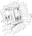
- FIG 3 shows the engine deck 6a within the aircraft upper deck 6 of Figure 2 with the engine deck skin 2i, which forms the engine accommodating region 7 above the fuselage 2, where two adjacent and spaced apart arrangements of engine compartments 20a, 20b are formed by firewall arrangement 10.
- Each of the engine compartments 20a, 20b are formed with the front firewall 10a, the rear firewall 10b, the mid firewall 10c, and the funnel-shaped lower firewall 10d.
- the gap 18 is formed between the two mid firewalls 10c and embodies a drive shaft channel 20c for a tail rotor drive shaft 12c.
- the engine deck 6a is shown without the aircraft engines 11a, 11b of Figure 2 to better illustrate arrangements of the front fixation points 16 of the front attachments 13, 14 and the rear fixation point 17 of the rear attachment 15.
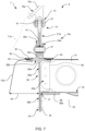
- the funnel-shaped lower firewall 10d preferably comprises the outer support surface 27a with an outer through-hole 28a through which an outer main mount bracket 29a extends at least partly.
- the funnel-shaped lower firewall 10d further comprises the inner support surface 27b with an inner through-hole 28b through which an inner main mount bracket 29b extends at least partly.
- the inner support surface 27b may be provided with another inner through-hole 28b through which an inner lateral mount bracket 25a may extend at least partly.
- outer main mount bracket 29a and the inner main mount bracket 29b together may be utilized as main mount brackets 29.
- the main mount brackets 29 together with the main mount fixations 24 may extend from below the funnel-shaped lower firewall 10d to above the funnel-shaped lower firewall 10d to support the installation of the main mounts 21, namely the outer main mount 21a and the inner main mount 21b.
- the funnel-shaped lower firewall 10d preferably further comprises the rear support surface 27c with a rear through-hole 28c through which a rear mount bracket 30 extends at least partly, wherein the rear mount bracket 30 is connected to the rear mount 23 that is attached to the at least one aircraft engine 11b of Figure 2 .
- rear mount bracket 30 may be provided with the rear mount fixation 26 extending through the rear through-hole 28c of the rear support surface 27c.
- the upper primary skin 2c of the fuselage 2 may comprise at least one engine deck skin cut-out 2l.
- the at least one engine deck skin cut-out 2l is illustratively located below the lower firewall support surfaces 27.
- the main mount brackets 29 and rear mount bracket 30 may preferably be arranged along the borders of the engine deck skin cut-out 2l.
- each (main) front mount bracket 29a, 29b is preferably provided with one longitudinal beam (2k in Figure 5 ) aligned with the longitudinal borders of the engine deck skin cut-out 2l
- each rear mount 23 is preferably provided with a transversal beam 2m which is aligned with the rear transversal border of the engine deck skin cut-out 2l.
- the transversal beams 2m are provided under the upper primary skin 2c in the area in which the rear mount 23 is located such that the transversal beams 2m support the rear mount 23.
- At least one stiffening rib 31 is arranged between the funnel-shaped lower firewall 10d and the upper primary skin 2c.
- the at least one stiffening rib 31 is described in more detail in Figure 5 .
- cover plates 32 may be provided for the main mounts 21, inner lateral mount 22, and the rear mount 23 for clamping the funnel-shaped lower firewall 10d.
- the arrangements of the cover plates 32 are described in more detail in Figure 6 .
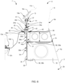
- Figure 5 shows a partially cut view of the engine compartment 20b of Figure 4 , where the front attachments 14 at front fixation points 16a, 16b and the rear attachment 15 at rear fixation point 17 are illustratively forming a triangular mounting plane 17a above the lower firewall support surfaces 27 of the funnel-shaped lower firewall 10d.
- the triangular mounting plane 17a may be formed by the inner main mounting bracket 16d, the outer main mounting bracket 16c, and a rear mounting bracket 16e.
- the rear mounting bracket 16e may be rigidly attached to the aircraft engine 11b of Figure 2 and rotatably mounted to the rear mount 23.
- At least one stiffening rib 31 is arranged between the funnel-shaped lower firewall 10d and the upper primary skin 2c.
- an upper web section (39a in Figure 6 ) of the main mount bracket webs (39 in Figure 6 ) may include an outer main mount bracket support rib 40 that is rigidly attached to the stiffening rib 31.
- an intercostal 33 may be arranged below the at least one stiffening rib 31.
- a center portion 10h of the funnel-shaped lower firewall 10d is arranged inside of the at least one engine deck skin cut-out 2l of Figure 4 .
- the funnel-shaped lower firewall 10d may have the inner collecting point 10f with the drainage 10e within the lower firewall center portion 10h of the funnel-shaped lower firewall 10d.
- a raised filter structure may be installed over the inner collecting point 10f to filter the liquid flowing through it.
Landscapes
- Engineering & Computer Science (AREA)
- Aviation & Aerospace Engineering (AREA)
- Mechanical Engineering (AREA)
- Aiming, Guidance, Guns With A Light Source, Armor, Camouflage, And Targets (AREA)
- Arrangement Or Mounting Of Propulsion Units For Vehicles (AREA)
Claims (15)
- Drehflügelflugzeug (1) mit einem Rumpf (2), der einen Flugzeuginnenbereich (2a, 2b) bildet, wobei der Rumpf (2) eine obere Primärhaut (2c) umfasst, die den Flugzeuginnenbereich (2a, 2b) von einem über dem Rumpf (2) angeordneten Flugzeugoberdeck (6) trennt, wobei die obere Primärhaut (2c) auf einer vorgegebenen Anzahl von Trägerbalken (2k) befestigt ist; wobei das FlugzeugOberdeck (6) einen Triebwerksaufnahmebereich (7) mit einer Brandschottanordnung (10) umfasst, wobei der Triebwerksaufnahmebereich (7) mindestens ein Flugzeugtriebwerk (11b) innerhalb der Brandschottanordnung (10) derart aufnimmt, dass die Brandschottanordnung (10) eine feuersichere Trennung zumindest zwischen dem mindestens einen Flugzeugtriebwerk (11b) und dem Flugzeuginnenbereich (2a, 2b) definiert; wobei die Brandschottanordnung (10) mindestens ein trichterförmiges unteres Brandschott (10d) umfasst, das zwischen dem mindestens einen Flugzeugtriebwerk (11b) und der oberen Primärhaut (2c) des Rumpfes (2) angeordnet ist, wobei das mindestens eine trichterförmige untere Brandschott (10d) von der oberen Primärhaut (2c) um einen vorgegebenen Trennabstand (36) beabstandet ist und von einem Außenumfang (10g) zu mindestens einem inneren Sammelpunkt (10f) des mindestens einen trichterförmigen unteren Brandschotts (10d) konvergiert; wobei das mindestens eine trichterförmige untere Brandschott (10d) mindestens eine äußere Stützfläche (27a) mit einem Durchgangsloch (28a) umfasst, durch das sich eine äußere Hauptbefestigungshalterung (29a) mindestens teilweise erstreckt, wobei die äußere Hauptbefestigungshalterung (29a) einen äußeren Hauptbefestigungshalterungssteg (39) umfasst; wobei die äußere Hauptbefestigungshalterung (29a) ferner ein an die äußere Stützfläche (27a) angrenzendes Plateau (39d) umfasst, wobei das Plateau (39d) mit einer äußeren Hauptbefestigungsfixierung (24a) versehen ist, die sich durch das Durchgangsloch (28a) der äußeren Stützfläche (27a) erstreckt, wobei die äußere Hauptbefestigungsfixierung (24a) mit einer äußeren Hauptbefestigung (21a) verbunden ist, die an dem mindestens einen Flugzeugtriebwerk (11b) angebracht ist,
dadurch gekennzeichnet, dass der äußere Hauptbefestigungshalterungssteg (39) starr an einem Balkensteg (35) mindestens eines Balkens (2k) der vorgegebenen Anzahl von Trägerbalken (2k) angebracht ist. - Drehflügelflugzeug (1) nach Anspruch 1, ferner umfassend eine Abdeckplatte (32), die starr an dem Plateau (39d) befestigt ist, um das mindestens eine trichterförmige untere Brandschott (10d) zwischen der Abdeckplatte (32) und dem Plateau (39d) einzuklemmen.
- Drehflügelflugzeug (1) nach Anspruch 2, ferner umfassend ein Dichtungselement (43), das zwischen der Abdeckplatte (32) und dem mindestens einen trichterförmigen unteren Brandschott (10d) und/oder zwischen dem Plateau (39d) und dem mindestens einen trichterförmigen unteren Brandschott (10d) geklemmt ist, um das mindestens eine trichterförmige untere Brandschott (10d) abzudichten.
- Drehflügelflugzeug (1) nach einem der vorhergehenden Ansprüche, bei dem der äußere Hauptbefestigungshalterungssteg (39) einen oberen Stegabschnitt (39a), der sich von der Plattform (39d) über den vorgegebenen Abstand (36) bis zum Balkensteg (35) des mindestens einen Balkens (2k) erstreckt, und einen unteren Stegabschnitt (39b) umfasst, der starr mit dem Steg (35) des mindestens einen Trägerbalkens (2k) verbunden ist.
- Drehflügelflugzeug (1) nach Anspruch 4 , ferner umfassend mindestens eine Versteifungsrippe (31), wobei die mindestens eine Versteifungsrippe (31) zwischen dem mindestens einen trichterförmigen unteren Brandschott (10d) und der oberen Primärhaut (2c) angeordnet ist, und wobei der obere Stegabschnitt (39a) eine Stützrippe (40) umfasst, die starr mit der mindestens einen Versteifungsrippe (31) verbunden ist.
- Drehflügelflugzeug (1) nach einem der vorhergehenden Ansprüche, bei dem die äußere Hauptbefestigungsfixierung (24a) mindestens einen Befestigungsansatz (39c) umfasst und bei dem die äußere Hauptbefestigung (21a) über mindestens ein Kugelgelenk (41) drehbar an dem mindestens einen Befestigungsansatz (39c) gelagert ist.
- Drehflügelflugzeug (1) nach Anspruch 6, bei dem die äußere Hauptbefestigung (21a) als dreieckiges Befestigungselement ausgebildet ist, das über zwei Kugelgelenklager (41) mit der äußeren Hauptbefestigung (24a) verbunden ist.
- Drehflügelflugzeug (1) nach einem der vorhergehenden Ansprüche, bei dem die äußere Hauptbefestigung (21a) drehbar an einer äußeren Hauptbefestigungshalterung (16c) befestigt ist, die starr an dem mindestens einen Flugzeugmotor (11b) angebracht ist.
- Drehflügelflugzeug (1) nach Anspruch 8, bei dem die äußere Hauptbefestigung (21a) über ein Kugelgelenk (41) drehbar an der äußeren Hauptbefestigungshalterung (16c) befestigt ist.
- Drehflügelflugzeug (1) nach einem der vorhergehenden Ansprüche, bei dem das mindestens eine trichterförmige untere Brandschott (10d) ferner eine innere Stützfläche (27b) mit einem Durchgangsloch (28b) umfasst, durch das sich eine innere Hauptbefestigungshalterung (29b) zumindest teilweise erstreckt, wobei die innere Hauptbefestigungshalterung (29b) mit einer inneren Hauptbefestigung (21b) verbunden ist, die an dem mindestens einen Flugzeugtriebwerk (11b) befestigt ist.
- Drehflügelflugzeug (1) nach Anspruch 10, bei dem die innere Hauptbefestigung (21b) drehbar an einer inneren Hauptbefestigungshalterung (16d) befestigt ist, die starr an dem mindestens einen Flugzeugtriebwerk (11b) befestigt ist.
- Drehflügelflugzeug (1) nach Anspruch 11, bei dem die innere Hauptbefestigungshalterung (16d) ferner an einer inneren seitlichen Halterung (22) drehbar befestigt ist, die mit einer inneren seitlichen Befestigungshalterung (25a) verbunden ist.
- Drehflügelflugzeug (1) nach einem der Ansprüche 10 bis 12, bei dem die innere Hauptbefestigungshalterung (29b) starr an einem Balkensteg (35) mindestens eines anderen Balkens (2k) der vorgegebenen Anzahl von Stützbalken (2k) befestigt ist.
- Drehflügelflugzeug (1) nach einem der vorhergehenden Ansprüche, bei dem das mindestens eine trichterförmige untere Brandschott (10d) ferner eine hintere Stützfläche (27c) mit einem hinteren Durchgangsloch (28c) umfasst, durch das sich eine hintere Befestigungshalterung (30) zumindest teilweise erstreckt, wobei die hintere Befestigungshalterung (30) mit einer hinteren Halterung (23) verbunden ist, die an dem mindestens einen Flugzeugtriebwerk (11b) befestigt ist.
- Drehflügelflugzeug (1) nach einem der vorhergehenden Ansprüche, bei dem die obere Primärhaut (2c) des Rumpfes (2) mindestens einen Ausschnitt (21) umfasst und bei dem ein Mittelteil (10h) des mindestens einen trichterförmigen unteren Brandschotts (10d) innerhalb des mindestens einen Ausschnitts (21) angeordnet ist.
Priority Applications (2)
| Application Number | Priority Date | Filing Date | Title |
|---|---|---|---|
| EP23171892.5A EP4458669B1 (de) | 2023-05-05 | 2023-05-05 | Drehflügelflugzeug mit einer firewall-anordnung mit mindestens einer trichterförmigen unteren firewall |
| US18/631,332 US12258121B2 (en) | 2023-05-05 | 2024-04-10 | Rotary wing aircraft with a firewall arrangement having at least one funnel-shaped lower firewall |
Applications Claiming Priority (1)
| Application Number | Priority Date | Filing Date | Title |
|---|---|---|---|
| EP23171892.5A EP4458669B1 (de) | 2023-05-05 | 2023-05-05 | Drehflügelflugzeug mit einer firewall-anordnung mit mindestens einer trichterförmigen unteren firewall |
Publications (2)
| Publication Number | Publication Date |
|---|---|
| EP4458669A1 EP4458669A1 (de) | 2024-11-06 |
| EP4458669B1 true EP4458669B1 (de) | 2025-07-02 |
Family
ID=86330226
Family Applications (1)
| Application Number | Title | Priority Date | Filing Date |
|---|---|---|---|
| EP23171892.5A Active EP4458669B1 (de) | 2023-05-05 | 2023-05-05 | Drehflügelflugzeug mit einer firewall-anordnung mit mindestens einer trichterförmigen unteren firewall |
Country Status (2)
| Country | Link |
|---|---|
| US (1) | US12258121B2 (de) |
| EP (1) | EP4458669B1 (de) |
Families Citing this family (2)
| Publication number | Priority date | Publication date | Assignee | Title |
|---|---|---|---|---|
| EP4458669B1 (de) * | 2023-05-05 | 2025-07-02 | AIRBUS HELICOPTERS DEUTSCHLAND GmbH | Drehflügelflugzeug mit einer firewall-anordnung mit mindestens einer trichterförmigen unteren firewall |
| US12582853B2 (en) * | 2023-07-03 | 2026-03-24 | Textron Innovations Inc. | Fire zone thermal protection for adjacent components |
Family Cites Families (14)
| Publication number | Priority date | Publication date | Assignee | Title |
|---|---|---|---|---|
| US5458343A (en) * | 1994-08-11 | 1995-10-17 | General Electric Company | Aircraft engine firewall seal |
| US8631637B2 (en) * | 2010-07-30 | 2014-01-21 | Hamilton Sundstrand Corporation | Auxiliary power unit fire enclosure |
| US8820045B2 (en) * | 2010-07-30 | 2014-09-02 | United Technologies Corporation | Auxiliary power unit fire enclosure drain seal |
| FR3015431B1 (fr) * | 2013-12-19 | 2017-12-15 | Airbus Operations Sas | Structure primaire de mat d'accrochage renforcee. |
| US10689126B2 (en) * | 2017-06-19 | 2020-06-23 | Bell Helicopter Textron Inc. | Two-piece firewall and inlet plenum |
| US10814995B2 (en) * | 2017-08-29 | 2020-10-27 | Spirit Aerosystems, Inc. | High-mounted aircraft nacelle |
| US10669038B2 (en) * | 2018-04-20 | 2020-06-02 | Textron Innovations Inc. | Engine inlet system with integral firewall seal |
| US11479104B2 (en) * | 2019-07-24 | 2022-10-25 | Honeywell International Inc. | System and method for gas turbine engine mount with seal |
| EP3932801B1 (de) | 2020-06-30 | 2022-05-18 | AIRBUS HELICOPTERS DEUTSCHLAND GmbH | Drehflügel-flugzeug mit einer brandschutzvorrichtung |
| US20220055756A1 (en) * | 2020-08-19 | 2022-02-24 | Pratt & Whitney Canada Corp. | Aircraft firewall feedthrough device |
| US11865382B2 (en) * | 2021-01-26 | 2024-01-09 | Textron Innovations Inc. | Fire extinguishing discharge nozzle for helicopter engine compartment |
| EP4071046B1 (de) * | 2021-04-09 | 2023-06-07 | AIRBUS HELICOPTERS DEUTSCHLAND GmbH | Drehflügelflugzeug mit einer feuerwandanordnung |
| FR3140117A1 (fr) * | 2022-09-27 | 2024-03-29 | Airbus Helicopters | Aéronef muni d’un moteur et d’un conduit d’échappement drainé autour d’une tuyère d’éjection du moteur |
| EP4458669B1 (de) * | 2023-05-05 | 2025-07-02 | AIRBUS HELICOPTERS DEUTSCHLAND GmbH | Drehflügelflugzeug mit einer firewall-anordnung mit mindestens einer trichterförmigen unteren firewall |
-
2023
- 2023-05-05 EP EP23171892.5A patent/EP4458669B1/de active Active
-
2024
- 2024-04-10 US US18/631,332 patent/US12258121B2/en active Active
Also Published As
| Publication number | Publication date |
|---|---|
| US20240367784A1 (en) | 2024-11-07 |
| EP4458669A1 (de) | 2024-11-06 |
| US12258121B2 (en) | 2025-03-25 |
Similar Documents
| Publication | Publication Date | Title |
|---|---|---|
| US12258121B2 (en) | Rotary wing aircraft with a firewall arrangement having at least one funnel-shaped lower firewall | |
| US11820485B2 (en) | Rotary wing aircraft with a firewall arrangement | |
| KR102651922B1 (ko) | 방화벽 구조물이 설치된 회전익 항공기 | |
| JP6188836B2 (ja) | 少なくとも内部領域と駆動系統収容領域とを規定する胴体を備えた航空機 | |
| US9975641B2 (en) | Aircraft propelling assembly including a duct forming a thermal barrier integrated in the caisson of the rigid structure of the engine mounting system | |
| US11220347B2 (en) | Modular subfloor arrangement for an aircraft | |
| EP3333064B1 (de) | Flugzeug mit einem airframe und mindestens einer elektrisch angetriebenen schuberzeugungseinheit | |
| RU2657650C1 (ru) | Рама мультикоптера (варианты) | |
| EP3556661B1 (de) | Triebwerkseinlasssystem mit integrierter feuerschutzwanddichtung | |
| CN114590392B (zh) | 用于旋翼航空器的防火墙装置的加强骨架 | |
| US20240092188A1 (en) | A rotorcraft with an energy source storage unit | |
| EP4717585A1 (de) | Drehflügelflugzeug mit einem rumpf mit einer lasttragenden schalenstruktur und einer lasttragenden versteifungselementstruktur | |
| EP4606704A1 (de) | Sitzträger für ein drehflügelflugzeug zur aufnahme von sitzpfosten einer sitzbankvorrichtung | |
| RU2600966C1 (ru) | Винтокрылый летательный аппарат |
Legal Events
| Date | Code | Title | Description |
|---|---|---|---|
| PUAI | Public reference made under article 153(3) epc to a published international application that has entered the european phase |
Free format text: ORIGINAL CODE: 0009012 |
|
| STAA | Information on the status of an ep patent application or granted ep patent |
Free format text: STATUS: THE APPLICATION HAS BEEN PUBLISHED |
|
| AK | Designated contracting states |
Kind code of ref document: A1 Designated state(s): AL AT BE BG CH CY CZ DE DK EE ES FI FR GB GR HR HU IE IS IT LI LT LU LV MC ME MK MT NL NO PL PT RO RS SE SI SK SM TR |
|
| STAA | Information on the status of an ep patent application or granted ep patent |
Free format text: STATUS: REQUEST FOR EXAMINATION WAS MADE |
|
| 17P | Request for examination filed |
Effective date: 20241107 |
|
| RBV | Designated contracting states (corrected) |
Designated state(s): AL AT BE BG CH CY CZ DE DK EE ES FI FR GB GR HR HU IE IS IT LI LT LU LV MC ME MK MT NL NO PL PT RO RS SE SI SK SM TR |
|
| P01 | Opt-out of the competence of the unified patent court (upc) registered |
Free format text: CASE NUMBER: APP_60156/2024 Effective date: 20241107 |
|
| GRAP | Despatch of communication of intention to grant a patent |
Free format text: ORIGINAL CODE: EPIDOSNIGR1 |
|
| STAA | Information on the status of an ep patent application or granted ep patent |
Free format text: STATUS: GRANT OF PATENT IS INTENDED |
|
| INTG | Intention to grant announced |
Effective date: 20250327 |
|
| GRAS | Grant fee paid |
Free format text: ORIGINAL CODE: EPIDOSNIGR3 |
|
| GRAA | (expected) grant |
Free format text: ORIGINAL CODE: 0009210 |
|
| STAA | Information on the status of an ep patent application or granted ep patent |
Free format text: STATUS: THE PATENT HAS BEEN GRANTED |
|
| AK | Designated contracting states |
Kind code of ref document: B1 Designated state(s): AL AT BE BG CH CY CZ DE DK EE ES FI FR GB GR HR HU IE IS IT LI LT LU LV MC ME MK MT NL NO PL PT RO RS SE SI SK SM TR |
|
| REG | Reference to a national code |
Ref country code: GB Ref legal event code: FG4D |
|
| REG | Reference to a national code |
Ref country code: CH Ref legal event code: EP |
|
| REG | Reference to a national code |
Ref country code: DE Ref legal event code: R096 Ref document number: 602023004417 Country of ref document: DE |
|
| REG | Reference to a national code |
Ref country code: IE Ref legal event code: FG4D |
|
| REG | Reference to a national code |
Ref country code: NL Ref legal event code: MP Effective date: 20250702 |
|
| PG25 | Lapsed in a contracting state [announced via postgrant information from national office to epo] |
Ref country code: PT Free format text: LAPSE BECAUSE OF FAILURE TO SUBMIT A TRANSLATION OF THE DESCRIPTION OR TO PAY THE FEE WITHIN THE PRESCRIBED TIME-LIMIT Effective date: 20251103 |
|
| PG25 | Lapsed in a contracting state [announced via postgrant information from national office to epo] |
Ref country code: NL Free format text: LAPSE BECAUSE OF FAILURE TO SUBMIT A TRANSLATION OF THE DESCRIPTION OR TO PAY THE FEE WITHIN THE PRESCRIBED TIME-LIMIT Effective date: 20250702 |
|
| REG | Reference to a national code |
Ref country code: AT Ref legal event code: MK05 Ref document number: 1808980 Country of ref document: AT Kind code of ref document: T Effective date: 20250702 |
|
| PG25 | Lapsed in a contracting state [announced via postgrant information from national office to epo] |
Ref country code: IS Free format text: LAPSE BECAUSE OF FAILURE TO SUBMIT A TRANSLATION OF THE DESCRIPTION OR TO PAY THE FEE WITHIN THE PRESCRIBED TIME-LIMIT Effective date: 20251102 |
|
| PG25 | Lapsed in a contracting state [announced via postgrant information from national office to epo] |
Ref country code: NO Free format text: LAPSE BECAUSE OF FAILURE TO SUBMIT A TRANSLATION OF THE DESCRIPTION OR TO PAY THE FEE WITHIN THE PRESCRIBED TIME-LIMIT Effective date: 20251002 |
|
| REG | Reference to a national code |
Ref country code: LT Ref legal event code: MG9D |
|
| PG25 | Lapsed in a contracting state [announced via postgrant information from national office to epo] |
Ref country code: AT Free format text: LAPSE BECAUSE OF FAILURE TO SUBMIT A TRANSLATION OF THE DESCRIPTION OR TO PAY THE FEE WITHIN THE PRESCRIBED TIME-LIMIT Effective date: 20250702 |
|
| PG25 | Lapsed in a contracting state [announced via postgrant information from national office to epo] |
Ref country code: FI Free format text: LAPSE BECAUSE OF FAILURE TO SUBMIT A TRANSLATION OF THE DESCRIPTION OR TO PAY THE FEE WITHIN THE PRESCRIBED TIME-LIMIT Effective date: 20250702 |
|
| PG25 | Lapsed in a contracting state [announced via postgrant information from national office to epo] |
Ref country code: HR Free format text: LAPSE BECAUSE OF FAILURE TO SUBMIT A TRANSLATION OF THE DESCRIPTION OR TO PAY THE FEE WITHIN THE PRESCRIBED TIME-LIMIT Effective date: 20250702 |
|
| PG25 | Lapsed in a contracting state [announced via postgrant information from national office to epo] |
Ref country code: GR Free format text: LAPSE BECAUSE OF FAILURE TO SUBMIT A TRANSLATION OF THE DESCRIPTION OR TO PAY THE FEE WITHIN THE PRESCRIBED TIME-LIMIT Effective date: 20251003 |
|
| PG25 | Lapsed in a contracting state [announced via postgrant information from national office to epo] |
Ref country code: CZ Free format text: LAPSE BECAUSE OF FAILURE TO SUBMIT A TRANSLATION OF THE DESCRIPTION OR TO PAY THE FEE WITHIN THE PRESCRIBED TIME-LIMIT Effective date: 20250702 Ref country code: SE Free format text: LAPSE BECAUSE OF FAILURE TO SUBMIT A TRANSLATION OF THE DESCRIPTION OR TO PAY THE FEE WITHIN THE PRESCRIBED TIME-LIMIT Effective date: 20250702 |
|
| PG25 | Lapsed in a contracting state [announced via postgrant information from national office to epo] |
Ref country code: LV Free format text: LAPSE BECAUSE OF FAILURE TO SUBMIT A TRANSLATION OF THE DESCRIPTION OR TO PAY THE FEE WITHIN THE PRESCRIBED TIME-LIMIT Effective date: 20250702 |
|
| PG25 | Lapsed in a contracting state [announced via postgrant information from national office to epo] |
Ref country code: BG Free format text: LAPSE BECAUSE OF FAILURE TO SUBMIT A TRANSLATION OF THE DESCRIPTION OR TO PAY THE FEE WITHIN THE PRESCRIBED TIME-LIMIT Effective date: 20250702 Ref country code: PL Free format text: LAPSE BECAUSE OF FAILURE TO SUBMIT A TRANSLATION OF THE DESCRIPTION OR TO PAY THE FEE WITHIN THE PRESCRIBED TIME-LIMIT Effective date: 20250702 |
|
| PG25 | Lapsed in a contracting state [announced via postgrant information from national office to epo] |
Ref country code: RS Free format text: LAPSE BECAUSE OF FAILURE TO SUBMIT A TRANSLATION OF THE DESCRIPTION OR TO PAY THE FEE WITHIN THE PRESCRIBED TIME-LIMIT Effective date: 20251002 |
|
| PG25 | Lapsed in a contracting state [announced via postgrant information from national office to epo] |
Ref country code: ES Free format text: LAPSE BECAUSE OF FAILURE TO SUBMIT A TRANSLATION OF THE DESCRIPTION OR TO PAY THE FEE WITHIN THE PRESCRIBED TIME-LIMIT Effective date: 20250702 |
|
| PG25 | Lapsed in a contracting state [announced via postgrant information from national office to epo] |
Ref country code: SM Free format text: LAPSE BECAUSE OF FAILURE TO SUBMIT A TRANSLATION OF THE DESCRIPTION OR TO PAY THE FEE WITHIN THE PRESCRIBED TIME-LIMIT Effective date: 20250702 |
|
| PG25 | Lapsed in a contracting state [announced via postgrant information from national office to epo] |
Ref country code: DK Free format text: LAPSE BECAUSE OF FAILURE TO SUBMIT A TRANSLATION OF THE DESCRIPTION OR TO PAY THE FEE WITHIN THE PRESCRIBED TIME-LIMIT Effective date: 20250702 |