EP4344913A1 - Thermal management system, vehicle, and thermal management method - Google Patents
Thermal management system, vehicle, and thermal management method Download PDFInfo
- Publication number
- EP4344913A1 EP4344913A1 EP22871416.8A EP22871416A EP4344913A1 EP 4344913 A1 EP4344913 A1 EP 4344913A1 EP 22871416 A EP22871416 A EP 22871416A EP 4344913 A1 EP4344913 A1 EP 4344913A1
- Authority
- EP
- European Patent Office
- Prior art keywords
- valve
- port
- pipeline
- communicates
- thermal management
- Prior art date
- Legal status (The legal status is an assumption and is not a legal conclusion. Google has not performed a legal analysis and makes no representation as to the accuracy of the status listed.)
- Granted
Links
Images





Classifications
-
- B—PERFORMING OPERATIONS; TRANSPORTING
- B60—VEHICLES IN GENERAL
- B60H—ARRANGEMENTS OF HEATING, COOLING, VENTILATING OR OTHER AIR-TREATING DEVICES SPECIALLY ADAPTED FOR PASSENGER OR GOODS SPACES OF VEHICLES
- B60H1/00—Heating, cooling or ventilating devices
- B60H1/32—Cooling devices
- B60H1/3204—Cooling devices using compression
- B60H1/3229—Cooling devices using compression characterised by constructional features, e.g. housings, mountings, conversion systems
-
- B—PERFORMING OPERATIONS; TRANSPORTING
- B60—VEHICLES IN GENERAL
- B60H—ARRANGEMENTS OF HEATING, COOLING, VENTILATING OR OTHER AIR-TREATING DEVICES SPECIALLY ADAPTED FOR PASSENGER OR GOODS SPACES OF VEHICLES
- B60H1/00—Heating, cooling or ventilating devices
- B60H1/00485—Valves for air-conditioning devices, e.g. thermostatic valves
-
- B—PERFORMING OPERATIONS; TRANSPORTING
- B60—VEHICLES IN GENERAL
- B60H—ARRANGEMENTS OF HEATING, COOLING, VENTILATING OR OTHER AIR-TREATING DEVICES SPECIALLY ADAPTED FOR PASSENGER OR GOODS SPACES OF VEHICLES
- B60H1/00—Heating, cooling or ventilating devices
- B60H1/00271—HVAC devices specially adapted for particular vehicle parts or components and being connected to the vehicle HVAC unit
- B60H1/00278—HVAC devices specially adapted for particular vehicle parts or components and being connected to the vehicle HVAC unit for the battery
-
- B—PERFORMING OPERATIONS; TRANSPORTING
- B60—VEHICLES IN GENERAL
- B60H—ARRANGEMENTS OF HEATING, COOLING, VENTILATING OR OTHER AIR-TREATING DEVICES SPECIALLY ADAPTED FOR PASSENGER OR GOODS SPACES OF VEHICLES
- B60H1/00—Heating, cooling or ventilating devices
- B60H1/00507—Details, e.g. mounting arrangements, desaeration devices
- B60H1/00557—Details of ducts or cables
- B60H1/00571—Details of ducts or cables of liquid ducts, e.g. for coolant liquids or refrigerants
-
- B—PERFORMING OPERATIONS; TRANSPORTING
- B60—VEHICLES IN GENERAL
- B60H—ARRANGEMENTS OF HEATING, COOLING, VENTILATING OR OTHER AIR-TREATING DEVICES SPECIALLY ADAPTED FOR PASSENGER OR GOODS SPACES OF VEHICLES
- B60H1/00—Heating, cooling or ventilating devices
- B60H1/00642—Control systems or circuits; Control members or indication devices for heating, cooling or ventilating devices
- B60H1/00814—Control systems or circuits characterised by their output, for controlling particular components of the heating, cooling or ventilating installation
- B60H1/00878—Control systems or circuits characterised by their output, for controlling particular components of the heating, cooling or ventilating installation the components being temperature regulating devices
- B60H1/00885—Controlling the flow of heating or cooling liquid, e.g. valves or pumps
-
- B—PERFORMING OPERATIONS; TRANSPORTING
- B60—VEHICLES IN GENERAL
- B60H—ARRANGEMENTS OF HEATING, COOLING, VENTILATING OR OTHER AIR-TREATING DEVICES SPECIALLY ADAPTED FOR PASSENGER OR GOODS SPACES OF VEHICLES
- B60H1/00—Heating, cooling or ventilating devices
- B60H1/02—Heating, cooling or ventilating devices the heat being derived from the propulsion plant
- B60H1/14—Heating, cooling or ventilating devices the heat being derived from the propulsion plant other than from cooling liquid of the plant
- B60H1/143—Heating, cooling or ventilating devices the heat being derived from the propulsion plant other than from cooling liquid of the plant the heat being derived from cooling an electric component, e.g. electric motors, electric circuits, fuel cells or batteries
-
- B—PERFORMING OPERATIONS; TRANSPORTING
- B60—VEHICLES IN GENERAL
- B60H—ARRANGEMENTS OF HEATING, COOLING, VENTILATING OR OTHER AIR-TREATING DEVICES SPECIALLY ADAPTED FOR PASSENGER OR GOODS SPACES OF VEHICLES
- B60H1/00—Heating, cooling or ventilating devices
- B60H1/32—Cooling devices
- B60H1/3204—Cooling devices using compression
- B60H1/3228—Cooling devices using compression characterised by refrigerant circuit configurations
- B60H1/32281—Cooling devices using compression characterised by refrigerant circuit configurations comprising a single secondary circuit, e.g. at evaporator or condenser side
-
- B—PERFORMING OPERATIONS; TRANSPORTING
- B60—VEHICLES IN GENERAL
- B60K—ARRANGEMENT OR MOUNTING OF PROPULSION UNITS OR OF TRANSMISSIONS IN VEHICLES; ARRANGEMENT OR MOUNTING OF PLURAL DIVERSE PRIME-MOVERS IN VEHICLES; AUXILIARY DRIVES FOR VEHICLES; INSTRUMENTATION OR DASHBOARDS FOR VEHICLES; ARRANGEMENTS IN CONNECTION WITH COOLING, AIR INTAKE, GAS EXHAUST OR FUEL SUPPLY OF PROPULSION UNITS IN VEHICLES
- B60K11/00—Arrangement in connection with cooling of propulsion units
- B60K11/02—Arrangement in connection with cooling of propulsion units with liquid cooling
-
- B—PERFORMING OPERATIONS; TRANSPORTING
- B60—VEHICLES IN GENERAL
- B60H—ARRANGEMENTS OF HEATING, COOLING, VENTILATING OR OTHER AIR-TREATING DEVICES SPECIALLY ADAPTED FOR PASSENGER OR GOODS SPACES OF VEHICLES
- B60H1/00—Heating, cooling or ventilating devices
- B60H1/32—Cooling devices
- B60H2001/3286—Constructional features
- B60H2001/3291—Locations with heat exchange within the refrigerant circuit itself
-
- B—PERFORMING OPERATIONS; TRANSPORTING
- B60—VEHICLES IN GENERAL
- B60K—ARRANGEMENT OR MOUNTING OF PROPULSION UNITS OR OF TRANSMISSIONS IN VEHICLES; ARRANGEMENT OR MOUNTING OF PLURAL DIVERSE PRIME-MOVERS IN VEHICLES; AUXILIARY DRIVES FOR VEHICLES; INSTRUMENTATION OR DASHBOARDS FOR VEHICLES; ARRANGEMENTS IN CONNECTION WITH COOLING, AIR INTAKE, GAS EXHAUST OR FUEL SUPPLY OF PROPULSION UNITS IN VEHICLES
- B60K1/00—Arrangement or mounting of electrical propulsion units
-
- B—PERFORMING OPERATIONS; TRANSPORTING
- B60—VEHICLES IN GENERAL
- B60K—ARRANGEMENT OR MOUNTING OF PROPULSION UNITS OR OF TRANSMISSIONS IN VEHICLES; ARRANGEMENT OR MOUNTING OF PLURAL DIVERSE PRIME-MOVERS IN VEHICLES; AUXILIARY DRIVES FOR VEHICLES; INSTRUMENTATION OR DASHBOARDS FOR VEHICLES; ARRANGEMENTS IN CONNECTION WITH COOLING, AIR INTAKE, GAS EXHAUST OR FUEL SUPPLY OF PROPULSION UNITS IN VEHICLES
- B60K1/00—Arrangement or mounting of electrical propulsion units
- B60K2001/003—Arrangement or mounting of electrical propulsion units with means for cooling the electrical propulsion units
-
- B—PERFORMING OPERATIONS; TRANSPORTING
- B60—VEHICLES IN GENERAL
- B60K—ARRANGEMENT OR MOUNTING OF PROPULSION UNITS OR OF TRANSMISSIONS IN VEHICLES; ARRANGEMENT OR MOUNTING OF PLURAL DIVERSE PRIME-MOVERS IN VEHICLES; AUXILIARY DRIVES FOR VEHICLES; INSTRUMENTATION OR DASHBOARDS FOR VEHICLES; ARRANGEMENTS IN CONNECTION WITH COOLING, AIR INTAKE, GAS EXHAUST OR FUEL SUPPLY OF PROPULSION UNITS IN VEHICLES
- B60K1/00—Arrangement or mounting of electrical propulsion units
- B60K2001/003—Arrangement or mounting of electrical propulsion units with means for cooling the electrical propulsion units
- B60K2001/005—Arrangement or mounting of electrical propulsion units with means for cooling the electrical propulsion units the electric storage means
-
- B—PERFORMING OPERATIONS; TRANSPORTING
- B60—VEHICLES IN GENERAL
- B60K—ARRANGEMENT OR MOUNTING OF PROPULSION UNITS OR OF TRANSMISSIONS IN VEHICLES; ARRANGEMENT OR MOUNTING OF PLURAL DIVERSE PRIME-MOVERS IN VEHICLES; AUXILIARY DRIVES FOR VEHICLES; INSTRUMENTATION OR DASHBOARDS FOR VEHICLES; ARRANGEMENTS IN CONNECTION WITH COOLING, AIR INTAKE, GAS EXHAUST OR FUEL SUPPLY OF PROPULSION UNITS IN VEHICLES
- B60K1/00—Arrangement or mounting of electrical propulsion units
- B60K2001/003—Arrangement or mounting of electrical propulsion units with means for cooling the electrical propulsion units
- B60K2001/006—Arrangement or mounting of electrical propulsion units with means for cooling the electrical propulsion units the electric motors
-
- F—MECHANICAL ENGINEERING; LIGHTING; HEATING; WEAPONS; BLASTING
- F25—REFRIGERATION OR COOLING; COMBINED HEATING AND REFRIGERATION SYSTEMS; HEAT PUMP SYSTEMS; MANUFACTURE OR STORAGE OF ICE; LIQUEFACTION SOLIDIFICATION OF GASES
- F25B—REFRIGERATION MACHINES, PLANTS OR SYSTEMS; COMBINED HEATING AND REFRIGERATION SYSTEMS; HEAT PUMP SYSTEMS
- F25B2339/00—Details of evaporators; Details of condensers
- F25B2339/04—Details of condensers
- F25B2339/047—Water-cooled condensers
-
- F—MECHANICAL ENGINEERING; LIGHTING; HEATING; WEAPONS; BLASTING
- F25—REFRIGERATION OR COOLING; COMBINED HEATING AND REFRIGERATION SYSTEMS; HEAT PUMP SYSTEMS; MANUFACTURE OR STORAGE OF ICE; LIQUEFACTION SOLIDIFICATION OF GASES
- F25B—REFRIGERATION MACHINES, PLANTS OR SYSTEMS; COMBINED HEATING AND REFRIGERATION SYSTEMS; HEAT PUMP SYSTEMS
- F25B2400/00—Component parts or details not otherwise provided for in this subclass
- F25B2400/23—Separators
Definitions
- the present application relates to the technology field of vehicles and, in particular, a thermal management system, a vehicle and a thermal management method.
- pure electric vehicles usually need to install many thermal management components, such as a water pump, a heat exchanger, a water-cooled condenser, a two-way solenoid valve, a two-way proportional valve and a cooling pipeline, according to the thermal management requirements of the whole vehicle.
- thermal management components such as a water pump, a heat exchanger, a water-cooled condenser, a two-way solenoid valve, a two-way proportional valve and a cooling pipeline, according to the thermal management requirements of the whole vehicle.
- thermal management components such as a water pump, a heat exchanger, a water-cooled condenser, a two-way solenoid valve, a two-way proportional valve and a cooling pipeline
- the present application provides a thermal management system, a vehicle and a thermal management method to solve the problems of using a large number of cooling pipeline connections in the prior art, which increases the length of the cooling pipeline in the entire system, increases the flow resistance of the cooling liquid in the cooling pipeline, and lowers the working efficiency of the thermal management system.
- a thermal management system for a vehicle includes: a tank assembly, a valve unit, a radiator and a heat exchanger, where the tank assembly includes a shell body and a cover plate, the shell body covers the cover plate and forms an accommodation chamber together with the cover plate and the valve unit is installed on the shell body.
- a plurality of pipelines for liquid circulation is disposed in the accommodation chamber, and the shell body has a plurality of connection ports communicating with the accommodation chamber, a first end of the pipeline communicates with the connection port in one-to-one correspondence, and a second end of the pipeline and a portion of the pipeline are located outside the accommodation chamber.
- the valve unit has a plurality of valve ports, and the valve ports communicate with the connection ports in one-to-one correspondence.
- the valve unit includes a first multi-way valve and a second multi-way valve, and the plurality of valve ports includes a plurality of first-valve-ports and a plurality of second-valve-ports, the first-valve-ports are located at the first multi-way valve, and the second-valve-ports are located at the second multi-way valve; the radiator and the heat exchanger communicate with different pipelines, respectively.
- a thermal management system for a vehicle includes: a tank assembly, a pump assembly, and a valve unit.
- the tank assembly includes a shell body and a cover plate, the shell body covers the cover plate and forms an accommodation chamber together with the cover plate, the pump assembly and the valve unit are each installed on the shell body.
- a plurality of pipelines for liquid circulation is disposed in the accommodation chamber, and the shell body has a plurality of connection ports communicating with the accommodation chamber, a first end of the pipeline communicates with the connection port in one-to-one correspondence, and a second end of the pipeline and a portion of the pipeline are located outside the accommodation chamber.
- the valve unit has a plurality of valve ports, and the valve ports communicate with the connection ports in one-to-one correspondence, and the valve units are configured for controlling a disconnection or connection between each connection port and its corresponding valve ports, so as to control the a disconnection or connection between the pipelines.
- a side of the shell body facing away from the cover plate has a first installation region and a second installation region
- the plurality of connection ports include a plurality of first connection ports and a plurality of second connection ports, the first connection ports are located in the first installation region, and the second connection ports are located in the second installation region.
- the valve unit includes a first multi-way valve and a second multi-way valve, and a plurality of valve ports include a plurality of first-valve-ports and a plurality of second-valve-ports, the first-valve-ports are located at the first multi-way valve, and the second-valve-ports are located at the second multi-way valve.
- the first multi-way valve is connected in the first installation region, and the first connection ports communicate with the first-valve-ports in one-to-one correspondence;
- the second multi-way valve is connected in the second installation region, and the second connection ports communicate with the second-valve-ports in one-to-one correspondence.
- a plurality of pipelines include a plurality of first pipelines, each first pipeline includes two first sub-pipelines, and a first end of one first sub-pipeline in each first pipeline corresponds to the first installation region, a second end of the one first sub-pipeline in each first pipeline is configured for communicating with a water outlet pipe of same component in a vehicle; a first end of the other first sub-pipeline in each first pipeline corresponds to the first installation region, and a second end of the other first sub-pipeline in the each first pipeline is configured for communicating with a water inlet pipe of same component in the vehicle.
- the component includes at least one of a radiator, a battery cooler, or a motor cooler.
- a plurality of pipelines include a second pipeline and a third pipeline, a first end of the second pipeline corresponds to the first installation region, and a first end of the third pipeline corresponds to the second installation region.
- the second pipeline includes two second sub-pipelines, one second sub-pipeline in the second pipeline is configured for communicating with a water outlet pipe of a warm-air core body in a vehicle, and the other second sub-pipeline in the second pipeline communicates with a water inlet pipe of a heater in the vehicle.
- the third pipeline includes two third sub-pipelines, one third sub-pipeline in the third pipeline is configured for communicating with a water outlet pipe of the heater, and the other third sub-pipeline in the third pipeline communicates with a water inlet pipe of the warm-air core body.
- a water storage region is disposed in the accommodation chamber, and the water storage region is located above each pipeline.
- the water storage region has a liquid replenishment port communicating with the pipeline.
- the thermal management system provided by the present application further includes a water-cooled condenser and a heat exchanger, the water-cooled condenser is installed on a side of the shell body facing away from the cover plate and has a first inlet and a first outlet, the heat exchanger is installed on a side of the cover plate facing away from the shell body and has a second inlet and a second outlet.
- the plurality of pipelines include two fourth pipelines, where a first end of one fourth pipeline corresponds to the second installation region and the one fourth pipeline communicates with the first inlet; and a first end of the other fourth pipeline corresponds to the first installation region, and the other fourth pipeline communicates with the first outlet.
- the plurality of pipelines include two fifth pipelines, where first ends of the fifth pipelines each correspond to the first installation region, one fifth pipeline communicates with the second outlet, and the other fifth pipeline communicates with the second inlet.
- the thermal management system provided by the present application further includes a gas-liquid separator
- the cover plate has an installation part that is located outside the accommodation chamber, and the gas-liquid separator is installed on a side of the installation part facing the shell body, and is adjacent to the water-cooled condenser.
- a refrigerant inlet of the gas-liquid separator communicates with a refrigerant outlet of the heat exchanger, and the gas-liquid separator is also configured for communicating with an outlet of an air-conditioning unit evaporator of the vehicle.
- the thermal management system provided by the present application further includes an integration valve of air conditioner, which is installed on a side of the installation part facing away from the shell body, the integration valve of air conditioner is adjacent to the heat exchanger, and the integration valve of air conditioner communicates with a refrigerant inlet of the water-cooled condenser and a refrigerant inlet of the heat exchanger, respectively.
- a refrigerant outlet of the water-cooled condenser communicates with the integration valve of air conditioner through a coaxial pipe.
- a refrigerant outlet of the gas-liquid separator communicates with a suction port of the compressor of the vehicle through a coaxial pipe.
- the coaxial pipe is also configured for communicating with an outlet of the condenser inside air-conditioning unit of the vehicle.
- the integration valve of air conditioner is configured for communicating with an inlet of the condenser inside air-conditioning unit, and is also configured for communicating with an exhaust port of the compressor.
- the pump assembly includes a heating water pump, a battery water pump, and a motor water pump.
- the heating water pump, the battery water pump, and the motor water pump are each installed on a side of the shell body facing away from the cover plate.
- the heating water pump, the battery water pump and the motor water pump are connected with different pipelines located outside the accommodation chamber, respectively.
- a vehicle including a vehicle body and a thermal management system installed on the vehicle body.
- a thermal management method which uses a thermal management system, the method includes the following steps:
- the thermal management method provided by the present application further includes the following steps:
- the thermal management method provided by the present application further includes the following steps:
- the thermal management method provided by the present application further includes the following steps:
- the thermal management method provided by the present application further includes the following steps:
- the thermal management method provided by the present application further includes the following steps: a part of the cooling liquid flowing out of the battery cooling mechanism flows into a controller, and the cooling liquid flowing out of the controller flows into the heat exchanger.
- the method further includes the following steps: controlling communication between the seventh first-valve-port and the eighth first-valve-port in the first multi-way valve, where the cooling liquid in the battery cooling mechanism flows into the heat exchanger through the controller, and the cooling liquid flowing out of the heat exchanger flows into the battery cooling mechanism through the seventh first-valve-port and the eighth first-valve-port.
- the method further includes the following steps:
- the present application provides a thermal management system, a vehicle, and a thermal management method.
- the thermal management system includes: a tank assembly and a valve unit, the tank assembly includes a shell body and a cover plate, the shell body covers the cover plate and forms an accommodation chamber together with the cover plate, the valve unit is installed on the shell body; a plurality of pipelines for liquid circulation is disposed in the accommodation chamber, the shell body has a plurality of connection ports communicating with the accommodation chamber, the first ends of the pipelines communicate with the connection ports in one-to-one correspondence, and the second ends of the pipelines and a portion of the pipeline are located outside the accommodation chamber; the valve unit has a plurality of valve ports, the valve ports communicate with the connection ports in one-to-one correspondence.
- each components of the thermal management system are integrated to install on the shell body and cover plate of the tank assembly, and the pipelines for cooling liquid circulation are integrated inside the accommodation chamber, thereby realizing the integration of the scattered installation components in the prior art into a module assembly.
- the highly integrated thermal management system not only effectively saves the installation space, but also saves a lot of pipelines, thereby reducing the flow resistance in the pipelines and improving the working efficiency of thermal management. It solves the problems of using a large number of cooling pipeline connections in the prior art, which leads to the increased length of the cooling pipeline in the entire system, increased flow resistance of the cooling liquid in the cooling pipeline, and lower working efficiency of the thermal management system.
- connection should be understood in a broad sense, for example, it can be fixed connection, or indirect connection through an intermediate, which may be the communication inside two elements or the interaction relationship between two elements.
- installation e.g., it can be fixed connection, or indirect connection through an intermediate, which may be the communication inside two elements or the interaction relationship between two elements.
- connection e.g., it can be fixed connection, or indirect connection through an intermediate, which may be the communication inside two elements or the interaction relationship between two elements.
- pure electric vehicles usually need to install many thermal management components, such as: an expansion water pump, a motor water pump, a battery water pump, a warm air water pump, a heat exchanger, a water-cooled condenser, a water temperature sensor, a four-way solenoid valve, a three-way solenoid valve, a two-way solenoid valve, a two-way proportional valve, a three-way proportional valve, a cooling connection pipeline, an air conditioner gas-liquid separator, an air conditioner EXV valve, an air conditioner SOV valve, an air conditioner connection pipeline, etc.
- thermal management components such as: an expansion water pump, a motor water pump, a battery water pump, a warm air water pump, a heat exchanger, a water-cooled condenser, a water temperature sensor, a four-way solenoid valve, a three-way solenoid valve, a two-way solenoid valve, a two-way proportional valve, a three-way proportional valve, a cooling connection pipeline
- the thermal management system will occupy a large installation space in the vehicle, and the scattered components need to use a large number of cooling pipelines and circulate pipelines for communication between them, thereby meeting the vehicle's demand for the thermal management of the components.
- the present application provides a thermal management system, a vehicle and a thermal management method. Through the integrated design of parts and components in the thermal management system of the vehicle, thereby saving the length of the pipelines in the thermal management system, and enhancing the working efficiency of the thermal management system.
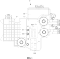
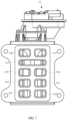
- FIG. 1 is a structural schematic diagram of a thermal management system provided by the present application
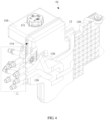
- FIG. 2 is another structural schematic diagram of the thermal management system provided by the present application
- FIG. 3 is a structural schematic diagram of the tank assembly in the thermal management system provided by the present application
- FIG. 4 is another structural schematic diagram of the tank assembly in the thermal management system provided by the present application.
- the thermal management system includes: a tank assembly 10, a pump assembly 20, and a valve unit 30.
- the tank assembly 10 includes a shell body 11 and a cover plate 12.
- the shell body 11 covers the cover plate 12 and forms an accommodation chamber (not shown in the figure) together with the cover plate 12.
- the pump assembly 20 and the valve unit 30 are installed on the shell body 11, respectively; the accommodation chamber is internally provided with a plurality of pipelines 130 for liquid circulation, and the shell body 11 has a plurality of connection ports 110 in communication with the accommodation chamber.
- a first end of the pipeline 130 communicates with the connection port 110 in one-to-one correspondence, and a second end of the pipeline 130 and a portion of the pipeline 130 are located outside the accommodation chamber;
- the valve unit 30 has a plurality of valve ports (not shown in the figure), and the valve ports communicate with the connection ports 110 in one-to-one correspondence.
- the valve unit 30 is used for controlling the disconnection or connection between the connection port 110 and the valve port corresponding to the connection port 110, thereby controlling the disconnection or connection between the pipelines.
- the tank assembly 10 is the core component of the thermal management system, and it has multiple functions.
- the tank assembly 10 can not only provide cooling liquid for cooling and reducing temperature to each component in the thermal management system, but also provide fixed support to each part and component, so as to integrate the dispersed components into an integrated thermal management module, so that an arrangement of respective components is more compact, thereby reducing the installation space of the thermal management system on the vehicle body.
- the tank assembly 10 includes a shell body 11 and a cover plate 12.
- the shell body 11 has a first surface 113 and a second surface (not shown in the figure) opposite to the first surface 113, the second surface of the shell body 11 is covered with the cover plate 12, and the shell body 11 is connected with the cover plate 12 by a hot plate welding process to form the accommodation chamber together with the cover plate 12.
- the pump assembly 20 and the valve unit 30 are each fixedly installed on the first surface 113 of the shell body 11.
- a plurality of pipelines 130 for the circulation of the cooling liquid are provided inside the accommodation chamber of the tank assembly 10, and the pipelines 130 are used for communicating with various components in the thermal management system and delivering cooling liquid to the corresponding components.
- a plurality of connection ports 110 are disposed in the first surface 113 of the shell body 11, and each connection port 110 communicates with the accommodation chamber.
- a first end of the pipeline 130 communicates with the connection port 110 in one-to-one correspondence, a second end of the pipeline 130 is located outside the accommodation chamber with a portion of the pipeline 130 after protruding from the accommodation chamber, and the second end of the pipeline 130 is used for communicating with the component installed on the shell body 11 to deliver the cooling liquid.
- the overall arrangement of the thermal management system becomes more compact, and the distance between various components also greatly reduced.
- setting the pipelines 130 for communicating between various components to be inside the accommodation chamber may not only optimize the spatial arrangement of the overall system, but also greatly shorten the total length of the pipeline 130, thereby effectively reducing the internal resistance of the pipeline 130, and improving the working efficiency of the thermal management system.
- the valve unit 30 is provided with a plurality of valve ports, which are communicated with the connection ports 110 in one-to-one correspondence. Each pipeline 130 communicates with the valve unit 30, and the cooling liquid flows into various components after passing through the valve unit 30.
- the valve unit 30 is configured for controlling the disconnection or connection between the connection port 110 and the corresponding valve port communicating with the connection port 110, thereby controlling the disconnection or connection between the pipelines 130 where various connection ports 110 are located, and then controlling the flow rate of the cooling liquid input to the components connected to various pipelines 130.
- valve unit 30 and the pipelines 130 which are installed in the thermal management system, are connected in series to form closed cooling loops.
- the opening and closing of different cooling loops is controlled by the valve unit 30, thereby meeting the requirements of various components for cooling liquid and improving the working efficiency of the overall thermal management system.
- each component in the thermal management system is integrally installed on the shell body 11 and the cover plate 12 in the tank assembly 10, and the pipeline 130 for cooling liquid circulation is integrated inside the accommodation chamber, thereby realizing the integration of the scattered installation components in the prior art into a module assembly.
- the highly integrated thermal management system not only effectively saves the installation space and unifies the external connection ports of the pipelines 130 to make the arrangement of the pipelines 130 more compact, but also saves a large number of pipelines 130, reduces the flow resistance in the pipelines 130 and improves the working efficiency of thermal management. It solves the problems of using a large number of cooling pipeline connections in the prior art, which leads to the increased length of the cooling pipeline in the entire system, increased flow resistance of the cooling liquid in the cooling pipeline, and lower working efficiency of the thermal management system.
- a side of the shell body 11 facing away from the cover plate 12 has a first installation region 111 and a second installation region 112, a plurality of connection ports 110 includes a plurality of first connection ports (not shown in the figure) and a plurality of second connection ports (not shown in the figure).
- the first connection port is located in the first installation region 111
- the second connection port is located in the second installation region 112.
- the side of the shell body 11 facing away from the cover plate 12 is the first surface 113 of the shell body 11, and the first surface 113 is provided with a first installation region 111 and a second installation region 112 for installing a valve assembly.
- FIG. 5 is an enlarged schematic diagram at A in FIG. 3
- FIG. 6 is an enlarged schematic diagram at B in FIG. 3 .
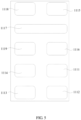
- first connection ports are provided in the first installation region 111, which are: a first connection port a 1111, a first connection port b 1112, a first connection port c 1113, a first connection port e 1114, a first connection port f 1115, a first connection port h 1116, a first connection port k 1117, a first connection port m 1118, and a first connection port n 1119, respectively.
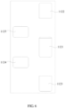
- the five second connection ports are provided in the second installation region 112, which are: a second connection port a 1121, a second connection port b 1122, a second connection port c 1123, a second connection port e 1124, and a second connection port f 1125, respectively.
- FIG. 7 is a structural schematic diagram of a first multi-way valve in the thermal management system provided by the present application
- FIG. 8 is a structural schematic diagram of a second multi-way valve in the thermal management system provided by the present application
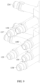
- FIG. 9 is an enlarged schematic diagram at C in FIG. 4 .
- the valve unit 30 includes a first multi-way valve 31 and a second multi-way valve 32, and the plurality of valve ports includes a plurality of first-valve-ports (not shown in the figure) and a plurality of second-valve-ports (not shown in the figure), where, the first-valve-ports are located on the first multi-way valve 31, and the second-valve-ports are located on the second multi-way valve 32.
- the first multi-way valve 31 includes a valve seat (not shown in the figure) and a valve core (not shown in the figure) rotatably disposed in the valve seat.
- the valve core has a plurality of rotating positions.
- the valve seat is provided with the plurality of first-valve-ports
- the valve core is provided with conduction structure groups respectively corresponding to various first-valve-ports.
- Each conduction structure group includes a plurality of conduction structures disposed along the circumferential direction; and the conduction unit group is configured as follows: when the valve core rotates to different rotating positions, different conduction structures in the conduction unit group cooperate with corresponding first-valve-ports, so that the first-valve-ports form different conduction states.
- the valve core is rotatably disposed on the valve seat, and the valve seat is provided with a plurality of first-valve-ports.
- the conduction structure group corresponding to the first-valve-port is disposed on the valve core, and further includes a plurality of conduction structures disposed along the circumferential direction. When the valve core rotates to different rotation positions, different first-valve-ports form different conduction states. Only one valve core is required.
- the first multi-way valve 31 may be a nine-way solenoid valve configured for controlling the disconnection or connection of each pipeline 130 connected to it.
- the nine-way solenoid valve is provided with nine first-valve-ports, which are: a first-valve-port a 311, a first-valve-port b 312, a first-valve-port c 313, a first-valve-port e 314, a first-valve-port f 315, a first-valve-port h 316, a first-valve-port k 317, a first-valve-port m 318, a first-valve-port n 319, respectively.
- the second multi-way valve 32 includes a valve seat, a first valve core (not shown in the figure), a second valve core (not shown in the figure) and a driving device (not shown in the figure).
- the driving device is connected to the first valve core in a transmission manner; the first valve core is provided with a first matching structure, and the second valve core is provided with a second matching structure matching with the first matching structure.
- the valve seat is provided with a plurality of second-valve-ports corresponding to the first valve core, and the valve core is provided with a first conduction structure, and the first conduction structure is configured for communicating at least two second-valve-ports when the first valve cores turn to a first predetermined position.
- the valve seat is provided with a plurality of second-valve-ports corresponding to the second valve, and the second valve core is provided with a second conduction structure, and the second conduction structure is configured for communicating at least two second-valve-ports when the two valve cores turn to the second predetermined position.
- the driving device is connected with the first valve core in a transmission manner.
- the first matching structure of the first valve core can drive the second valve core to rotate by the second matching structure.
- the first valve core can rotate independently, and the flow rate of the first valve core may be adjusted by changing the corresponding angle between the first-valve-port and the first conducting structure.
- the first valve core rotates, it drives the second spool to rotate; and by changing the corresponding angle between the second-valve-port and the second conduction structure, the flow rate of the second valve core may be adjusted, and the first-valve-port rotates to the original position again, without changing the flow of the first valve core. Only one drive device is required to drive and control the first valve core and the second valve core.
- the driving device includes a motor (not shown in the figure) and a gear set (not shown in the figure) connected to the motor in a transmission manner, and the gear set is connected to the first valve core in a transmission manner.
- a worm (not shown in the figure) is disposed on the motor shaft.
- the gear set includes a first worm gear cooperating with the worm, a second worm gear engaged with the first worm gear, a third worm gear engaged with the second worm gear, a first gear connected to the bottom of the third worm gear, and a second gear engaged with the first gear.
- the central axes of the first worm gear, the second worm gear, the third worm gear, the first gear and the second gear in the gear set are parallel to each other and are all disposed along the vertical direction, and the central axis of the first worm and the central axis of the first worm gear are perpendicular to each other.
- the worm disposed on the motor shaft rotates and drives the first valve core to rotate through the transmission of the gear set, thereby ensuring the stability of transmission.
- the type of the motor is not limited, and for control simplicity and high precision, preferably, the motor is a stepper motor or a servo motor.
- the second multi-way valve 32 is a five-way solenoid valve, and the five-way solenoid valve is configured for controlling the opening size of various pipelines 130 connected thereto, thereby controlling the flow rate of the cooling liquid flowing through the pipelines 130.
- the five-way solenoid valve is provided with five second-valve-ports, which are: a second-valve-port a 321, a second-valve-port b 322, a second-valve-port c 323, a second-valve-port e 324, and a second-valve-port f 325, respectively.
- the first multi-way valve 31 is connected in the first installation region 111, and the first-valve-port communicates with the first connection port in one-to-one correspondence.
- the second multi-way valve 32 is connected in the second installation region 112, and the second-valve-port communicates with the second connection port in one-to-one correspondence.
- each first-valve-port is in one-to-one correspondence with and communicated with each first connection port each other, where the first-valve-port a 311 communicates with the first connection port a 1111 correspondingly, the first-valve-port b 312 communicates with the first connection port b 1112 correspondingly, the first-valve-port c 313 communicates with the first connection port c 1113 correspondingly, the first-valve-port e 314 communicates with the first connection port e 1114 correspondingly, and the first-valve-port f 315 communicates with the first connection port f 1115 correspondingly, the first-valve-port h 316 communicates with the first connection port h 1116 correspondingly, the first-valve-port k 317 communicates with the first connection port k 1117 correspondingly, the first-valve-port m 318 communicates with the first
- each second-valve-port is in one-to-one correspondence with and communicated with each second connection port each other, where the second-valve-port a 321 communicates with the second connection port a 1121 correspondingly, the second-valve-port b 322 communicates with the second connection port b 1122 correspondingly, the second-valve-port c 323 communicates with the second connection port c 1123 correspondingly, the second-valve-port e 324 communicates with the second connection port e 1124 correspondingly, and the second-valve-port f 325 communicates with the second connection port f 1125 correspondingly.
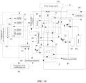
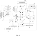
- FIG. 10 is a schematic circulation diagram of the thermal management system provided by the present application.
- the plurality of pipelines 130 includes a plurality of first pipelines (not shown in the figure), each first pipeline including two first sub-pipelines (not shown in the figure).
- a first end of one first sub-pipeline in each first pipeline corresponds to the first installation region 111, and a second end of the one first sub-pipeline in each first pipeline is configured for communicating with the water outlet pipe of the same component in the vehicle.
- a first end of the other first sub-pipeline in each first pipeline corresponds to the first installation region 111, a second end of the other first sub-pipeline in each first pipeline is configured for communicating with the water inlet pipe of the same component in the vehicle.
- the component includes at least one of a radiator 82, a battery cooling mechanism (referring to: a battery pack heat dissipating device, hereinafter abbreviated as: a battery cooling mechanism) 83, or a motor cooling mechanism (referring to: a motor heat dissipating device, hereinafter abbreviated as: motor cooling mechanism) 80.
- a battery cooling mechanism referring to: a battery pack heat dissipating device, hereinafter abbreviated as: a battery cooling mechanism
- motor cooling mechanism referring to: a motor heat dissipating device, hereinafter abbreviated as: motor cooling mechanism 80.
- the pipeline 130 disposed in the accommodation chamber includes a plurality of first pipelines, each first pipeline includes two first sub-pipelines, and the two first sub-pipelines are connected by the first multi-way valve 31 to form a first pipeline for the flow of cooling liquid.
- a first end of one first sub-pipeline in each first pipeline corresponds to and communicates with the first connection port in the first installation region 111
- a second end of the one first sub-pipeline in each first pipeline is configured for communicating with the water outlet pipe of the same component in the vehicle, and the cooling liquid flowing out of the component flows into the first multi-way valve 31 after passing through the first sub-pipeline.
- a first end of the other first sub-pipeline in each first pipeline corresponds to and communicates with the first connection port in the first installation region 111, and a second end of the other first sub-pipeline in each first pipeline is configured for communicating with the water inlet pipe of the same component in the vehicle, and the cooling liquid flowing out of the first multi-way valve 31 flows into the component after passing through the first sub-pipeline.
- the first ends of the two first sub-pipelines are connected through the first multi-way valve 31 to form the first pipeline, and then the first pipeline is communicated with the water inlet pipe and the water outlet pipe of the same component in the vehicle to form a closed cooling loop.
- the opening and closing state of the cooling loop is controlled by the first multi-way valve 31, so as to provide the cooling liquid for the components in the vehicle.
- the components in the vehicle where the circulation of the cooling liquid is usually present mainly include the radiator 82, the battery cooling mechanism 83, the motor cooling mechanism 80 and other components.
- the battery cooling mechanism 83 is a cooling mechanism disposed on the battery pack of the vehicle, which is mainly attached to the battery pack for exchanging heat with the battery pack. After the cooling liquid flow through the cooling mechanism, it can absorb and take away the heat generated from the battery pack, so that the battery pack is in a range of better temperature during operation.
- the motor cooling mechanism 80 is a cooling mechanism disposed on the motor of the vehicle, which is attached to the outer shell body of the motor for heat exchange.
- the motor cooling mechanism 80 When the vehicle's motor starts to work, it will generate a large amount of heat. If the heat cannot be released in time, it will affect the working performance of the vehicle's motor. Therefore, after the cooling liquid flows through the cooling device on the vehicle motor, it can absorb and take away the heat generated from the motor, so that the vehicle's motor is in a range of better temperature during operation.
- the radiator 82 is a device that is disposed in the vehicle for exchanging heat with the air. After the cooling liquid brings the absorbed heat to the radiator 82, the radiator 82 exchanges heat with the air so that it can transfer the heat to the air, thereby ensuring the normal operation of the vehicle.
- second ends of the plurality of first sub-pipelines protrude from the accommodation chamber out of the shell body 11 to form a plurality of connection ports communicating with related components in the vehicle.
- a water inlet pipe of radiator 131, a water outlet pipe of radiator 132, a water inlet pipe of motor cooling mechanism 133, and a water inlet pipe of battery cooling mechanism 135 are provided on the first surface 113 of the shell body 11; and a water outlet pipe of motor cooling mechanism 134 and a water outlet pipe of battery cooling mechanism 136 are provided on a first side 114 of the shell body 11.
- the liquid inlet and the liquid outlet of the radiator 82 of the vehicle are communicated with the water inlet pipe of radiator 131 and the water outlet pipe of radiator 132, respectively; and the liquid inlet and the liquid outlet of the battery cooling mechanism 83 are communicated with the water inlet pipe of battery cooling mechanism 135 and the water outlet pipe of battery cooling mechanism 136, respectively.
- the liquid inlet and the liquid outlet of the motor cooling mechanism 80 are communicated with the water inlet pipe of motor cooling mechanism 133 and the water outlet pipe of motor cooling mechanism 134, respectively.
- a plurality of pipelines 130 include a second pipeline (not shown in the figure) and a third pipeline (not shown in the figure).
- a first end of the second pipeline corresponds to the first installation region 111
- a first end of the third pipeline corresponds to the second installation region 112.
- the second pipeline includes two second sub-pipelines (not shown in the figure), and one second sub-pipeline of the second pipeline is configured for communicating with the water outlet pipe of the warm-air core body 85 in the vehicle, and the other second sub-pipeline of the second pipeline communicates with the water inlet pipe of the heater 84 in the vehicle.
- the third pipeline includes two third sub-pipelines (not shown in the figure), and one third sub-pipeline of the third pipeline is configured for communicating with the water outlet pipe of heater 84, and the other third sub-pipeline of the third pipeline communicates with the water inlet pipe of the warm-air core body 85.
- the second pipeline includes two second sub-pipelines.
- a first end of one second sub-pipeline of the second pipeline is disposed in correspondence to the first installation region 111, and a second end of the one second sub-pipeline of the second pipeline is configured for communicating with the water outlet pipe of the warm-air core body 85 in the vehicle.
- a first end of the other second sub-pipeline of the second pipeline is disposed in correspondence to the first installation region 111, and a second end of the other second sub-pipeline of the second pipeline is configured for communicating with the water inlet pipe of the heater 84 in the vehicle.
- the third pipeline includes two third sub-pipelines.
- a first end of one third sub-pipeline of the third pipeline is disposed in correspondence to the second installation region 112, and a second end of the one third sub-pipeline of the third pipeline is configured for communicating with the water outlet pipe of the heater 84.
- a first end of the other third sub-pipeline of the third pipeline is disposed in correspondence to the second installation region 112, and a second end of the other third sub-pipeline of the third pipeline is configured for communicating with the water inlet pipe of the warm-air core body 85.
- Both the heater 84 and the warm-air core body 85 are disposed on the vehicle body of the vehicle to provide warm air for a cockpit.
- the cockpit refers to a space that is disposed on the body of the vehicle in which the driver and passengers of vehicle ride.
- the heater 84 and the warm-air core body 85 are connected in series, and the cooling liquid flows through the heater 84 and the warm-air core body 85 sequentially after flowing out of the accommodation chamber.
- the cooling liquid flowing through the heater 84 can be heated up by starting the heater 84 to work, and then the cooling liquid after absorbing heat flows into the warm-air core body 85 through the pipeline 130.
- the warm-air core body 85 transfers heat to the cockpit through heat exchange, thereby increasing the temperature inside the cockpit.
- a fan (not shown in the figure) may be disposed at the position where the warm-air core body 85 is located, and blowing the air to the warm-air core body 85 by the fan enhances the heat exchange efficiency of the warm-air core body 85.
- a water inlet pipe of heater 137, a water outlet pipe of heater 138, a water inlet pipe of warm-air core body 139 and a water outlet pipe of warm-air core body 140 are provided on the first side 114 of the shell body 11.
- liquid inlet and the liquid outlet of the heater 84 communicate with the water inlet pipe of heater 137 and the water outlet pipe of heater 138 respectively; and the liquid inlet and the liquid outlet of the warm-air core body 85 communicate with the water inlet pipe of warm-air core body 139 and the water outlet pipe of warm-air core body 140 respectively.
- the accommodation chamber is internally provided with a water storage region 150.
- the water storage region 150 is located above the pipeline 130 and has a liquid replenishment port (not shown in the figure), where the liquid replenishment port communicates with the pipeline 130 to replenish water to the pipeline 130.
- the water storage region 150 is also provided in the accommodation chamber.
- the water storage region 150 is disposed above the pipeline 130.
- the shell body 11 is also provided with an injection port 151 located above the water storage region 150, the injection port 151 communicates with the water storage region 150, and the cooling liquid is added into the water storage region 150 through the injection port 151.
- the liquid replenishment port is provided below the water storage region 150 and communicates with the pipeline 130, the cooling liquid in the water storage region 150 is fed into each pipeline 130 through the liquid replenishment port for use by each component. It should be noted that, the opening and closing states of the injection port 151 and of the liquid replenishment port may be self-controlled by the thermal management system according to the loss degree of the cooling liquid.
- a water-cooled condenser 40 and a heat exchanger 50 are further included.
- the water-cooled condenser 40 is installed on the side of shell body 11 facing away from the cover plate 12, and has a first inlet (not shown in the figure) and a first outlet (not shown in the figure);
- the heat exchanger 50 is installed on the side of the cover plate 12 facing away from the shell body 11, and has a second inlet (not shown in the figure) and a second outlet (not shown in the figure).
- a plurality of pipelines 130 include two fourth pipelines (not shown in the figure).
- a first end of one fourth pipeline corresponds to the second installation region 112, and the one fourth pipeline communicates with the first inlet; and a first end of the other fourth pipeline corresponds to the first installation region 111, and the other fourth pipeline communicates with the first outlet.
- a plurality of pipelines 130 include two fifth pipelines (not shown in the figure). First ends of the fifth pipelines each correspond to the first installation region 111, one fifth pipeline communicates with the second outlet, and the other fifth pipeline communicates with the second inlet.
- the thermal management system in order to facilitate the thermal management system to dissipate heat from the air-conditioning system in the vehicle, the thermal management system further includes a water-cooled condenser 40 installed on the first surface 113 of the shell body 11.
- the water-cooled condenser 40 is a device for heat exchange between the refrigerant in the air-conditioning system and the cooling liquid in the thermal management system.
- the cooling liquid and the refrigerant are injected into the water-cooled condenser 40 at the same time, the refrigerant may transfer the heat in the air-conditioning system to the water-cooled condenser 40, and then the heat is absorbed by the cooling liquid and transferred to the thermal management system, so that the temperature of the refrigerant can drop rapidly, thereby achieving the purpose of cooling the air-conditioning system.
- the water-cooled condenser 40 is provided with a refrigerant inlet (not shown in the figure) and a refrigerant outlet (not shown in the figure) for the circulation of the refrigerant, as well as a first inlet (not shown in the figure) and a first outlet (not shown in the figure) for the circulation of the cooling liquid.
- the refrigerant inlet and the refrigerant outlet of the water-cooled condenser 40 communicate with the pipelines in the air conditioning system, respectively.
- the thermal management system further includes a heat exchanger 50 installed on the side of the cover plate 12 facing away from the shell body 11.
- the heat exchanger 50 is a device for heat exchange between the refrigerant in the air conditioning system and the cooling liquid in the thermal management system.
- the cooling liquid and the refrigerant are injected into the heat exchanger 50 at the same time, the cooling liquid transfers the heat in the thermal management system to the heat exchanger 50, and then the heat is absorbed by the refrigerant and transferred to the air conditioning system, so that the temperature of the cooling liquid can drop rapidly, thereby achieving the purpose of cooling the thermal management system.
- the heat exchanger 50 is provided with a refrigerant inlet (not shown in the figure) and a refrigerant outlet (not shown in the figure) for the circulation of the refrigerant, as well as a second inlet (not shown in the figure) and a second outlet (not shown in the figure) for the circulation of the cooling liquid.
- the refrigerant inlet and the refrigerant outlet of the heat exchanger 50 communicate with the pipelines in the air conditioning system, respectively.
- the plurality of pipelines 130 in the accommodation chamber include two fourth pipelines (not shown in the figure), where, a first end of one fourth pipeline corresponds to the second installation region 112 and communicates with the second connection port f 1125 in the second installation region 112, and the other end of the one fourth pipeline corresponds to and communicates with the first inlet of the water-cooled condenser 40.
- a first end of the other fourth pipeline corresponds to the first installation region 111 and communicates with the first connection port m 1118 in the first installation region 111.
- the cooling liquid flows out of the second connection port f 1125 and flows into the first inlet of the water-cooled condenser through the fourth pipeline, and then flows out of the first outlet of the water-cooled condenser 40 and flows into the first connection port m 1118 through the fourth pipeline, forming a cooling loop of the water-cooled condenser 40.
- the plurality of pipelines 130 in the accommodation chamber further include two fifth pipelines (not shown in the figure), where a first end of one fifth pipeline corresponds to the first installation region 111 and communicates with the first connection port h 1116 in the first installation region 111, and a second end of the one fifth pipeline corresponds to and communicates with the second inlet of the heat exchanger 50.
- a first end of the other fifth pipeline corresponds to the first installation region 111 and communicates with the first connection port b 1112 in the first installation region 111, and its second end corresponds to and communicates with the second outlet of the heat exchanger 50.
- the cooling liquid flows out of the first port h 1116 and flows into the second inlet of the heat exchanger 50 through the fifth pipeline, and then flows out of the first outlet of the heat exchanger 50 and flows into the first connection port b 1112 through the fifth pipeline, forming a cooling loop of the heat exchanger 50.
- a gas-liquid separator 60 is further included.
- the cover plate 12 has an installation part 120 located outside the accommodation chamber, and the gas-liquid separator 60 is installed on a side of the installation part 120 facing the shell body 11 and is adjacent to the water-cooled condenser 40.
- the refrigerant inlet of the gas-liquid separator 60 communicates with the refrigerant outlet of the heat exchanger 50, and the gas-liquid separator 60 is also configured for communicating with an outlet of an evaporator of air-conditioning unit of the vehicle.
- the thermal management system further includes the gas-liquid separator 60.
- the gas-liquid separator 60 is installed on the cover plate 12.
- the cover plate 12 is provided with the installation part 120, which is located outside the accommodation chamber.
- the gas-liquid separator 60 is installed on the side of the installation part 120 facing the first surface 113 of the shell body 11, and is disposed adjacent to the water-cooled condenser 40.
- the gas-liquid separator 60 is provided with a refrigerant inlet and a refrigerant outlet, and the refrigerant inlet of the gas-liquid separator 60 communicates with the refrigerant outlet of the heat exchanger 50 and the refrigerant outlet of the evaporator of air-conditioning unit 90.
- the refrigerant outlet of the gas-liquid separator 60 communicates with the refrigerant outlet of the compressor 91.
- the refrigerants output from the heat exchanger 50 and the evaporator of air-conditioning unit 90 are subjected to gas-liquid separation after feeding into the gas-liquid separator 60, where the gaseous refrigerant is fed from the gas-liquid separator 60 into the compressor 91 for recycling.
- an integration valve of air conditioner 70 is further included.
- the integration valve of air conditioner 70 is installed on the side of the installation part 120 facing away from the shell body 11, and is adjacent to the heat exchanger 50.
- the integration valve of air conditioner 70 communicates with the refrigerant inlet of the water-cooled condenser 40 and the refrigerant inlet of the heat exchanger 50;
- the refrigerant outlet of the water-cooled condenser 40 communicates with the integration valve of air conditioner 70 through the coaxial pipe 93;
- the refrigerant outlet of the gas-liquid separator 60 communicates with a suction port of a compressor 91 of the vehicle through the coaxial pipe 93;
- the coaxial pipe 93 is also configured for communicating with an outlet of the condenser of air-conditioning unit 92 of the vehicle;
- the integration valve of air conditioner 70 is configured for communicating with an inlet of the condenser of air-conditioning unit 92, and the integration valve of air conditioner 70 is also configured for communicating with the exhaust port of the
- the thermal management system further includes an integration valve of air conditioner 70.
- the integration valve of air conditioner 70 is installed on the side of the installation part 120 facing away from the shell body 11, and is disposed adjacent to the heat exchanger 50.
- Two switch valves and two expansion valves are disposed on the integration valve of air conditioner 70 at intervals, which are a first switch valve 71, a second switch valve 72, a first expansion valve 73 and a second expansion valve 74, respectively.
- the first switch valve 71 and the second switch valve 72 are disposed in parallel, and inlets of them communicate with the exhaust port of the compressor 91 through the pipelines.
- An outlet of the first switch valve 71 communicates with the refrigerant inlet of the condenser of air-conditioning unit 92 through a pipeline, and an outlet of the second switch valve 72 communicates with the refrigerant inlet of the water-cooled condenser 40 through a pipeline.
- the refrigerant output from the exhaust port of the compressor 91 passes through the first switch valve 71 and then feeds into the condenser of air conditioner 92; otherwise, the refrigerant will be fed into the water-cooled condenser 40 through the second switch valve 72.
- the first expansion valve 73 and the second expansion valve 74 are disposed in parallel, and inlets of them each communicate with the coaxial pipe 93 through pipelines.
- An outlet of the first expansion valve 73 communicates with the refrigerant inlet of the heat exchanger 50 through a pipeline
- an outlet of the second expansion valve 74 communicates with the evaporator of air-conditioning unit 90 through a pipeline.
- the two expansion valves may be turned on at the same time, that is, the refrigerant output from the coaxial pipe 93 may enter the two expansion valves at the same time so as to be fed to different components.
- the refrigerant outlet of the water-cooled condenser 40 communicates with the expansion valve through the coaxial pipe 93
- the refrigerant outlet of the gas-liquid separator 60 communicates with the suction port of the compressor 91 through the coaxial pipe 93
- the refrigerant outlet of the condenser of air-conditioning unit 92 communicates with the expansion valve through the coaxial pipe 93.
- the circulate route of the refrigerant in the vehicle's air-conditioning system is as follows: after the refrigerant is fed from the exhaust port of the compressor 91 to the integration valve of air conditioner 70, there are two routes to choose. In first route, the refrigerant is fed into the condenser of air-conditioning unit 92 after passing through the first switch valve 71, and then fed into the coaxial pipe 93, and fed to the expansion valve from the coaxial pipe 93; in second route, the refrigerant is fed to the water-cooled condenser 40 after passing through the second switch valve 72, and then fed to the coaxial pipe 93, and fed to the expansion valve from the coaxial pipe 93.
- the refrigerant output from the expansion valve is divided into two paths.
- first path the refrigerant is fed from the first expansion valve 73 to the heat exchanger 50, and then fed to the gas-liquid separator 60, and fed to the compressor 91 through the coaxial pipe 93, forming a complete refrigerant circulation loop.
- second path the refrigerant is fed from the second expansion valve 74 into the evaporator of air-conditioning unit 90, and then fed into the gas-liquid separator 60, and fed into the compressor 91 through the coaxial pipe 93, forming a complete refrigerant circulation loop.
- the pump assembly 20 includes a heating water pump 21, a battery water pump 22 and a motor water pump 23; the heating water pump 21, the battery water pump 22 and the motor water pump 23 are each installed on a side of the shell body 11 facing away from the cover plate 12; and the heating water pump 21, the battery water pump 22 and the motor water pump 23 communicate with different pipelines located outside the accommodation chamber, respectively.
- the pump assembly 20 installed on the first surface 113 of the shell body 11 includes the heating water pump 21, the battery water pump 22 and the motor water pump 23.
- the heating water pump 21 and the heater 84 are connected in series, and a water outlet of the heating water pump 21 communicates with a water inlet of the heater 84 through the pipeline 130, and the heating water pump 21 can speed up the rate of the cooling liquid feeding into the heater 84.
- a water outlet of the battery water pump 22 communicates with a water inlet of the battery cooling mechanism 83 through the pipeline 130, and the battery water pump 22 can speed up the rate of the cooling liquid feeding into the battery cooling mechanism 83.
- a water outlet of the motor water pump 23 communicates with a water inlet of the motor cooling mechanism 80, and the motor water pump 23 can speed up the rate of the cooling liquid feeding into the motor cooling mechanism 80.
- the present application also provides a vehicle, including a vehicle body and a thermal management system and an air-conditioning system installed on the vehicle body.
- the thermal management system and the air conditioning system have been explained in detail in the above contents, and will not be repeated here.
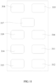
- FIG. 11 is an enlarged schematic diagram at D in FIG. 10
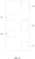
- FIG. 12 is an enlarged schematic diagram at E in FIG. 10 .
- the combination of solid line and arrow represents the flow direction of the cooling liquid
- the combination of dotted line and arrow represents the flow direction of the refrigerant
- the combination of double-dot dash line and arrow represents the flow direction during replenishment of the cooling liquid.
- the heat conduction route of the thermal management system includes a cooling liquid loop communicated by a solid line and a refrigerant loop communicated by a dotted line in the figure.
- the cooling liquid loop the heat is mainly transferred by the cooling liquid
- the refrigerant loop the heat is mainly transferred by the refrigerant.
- the cooling liquid loop uses the pipeline 130 to communicate with various components
- the refrigerant loop uses the air conditioner pipeline (not shown in the figure) to communicate with various components.
- the cooling liquid loop mainly includes a motor cooling mechanism loop, a battery cooling mechanism loop and a warm air loop.
- a liquid outlet of the motor cooling mechanism (referring to: a motor heat dissipating device, hereinafter abbreviated as: motor cooling mechanism) 80 communicates with the first-valve-port m 318
- a liquid inlet of the motor water pump 23 communicates with the first-valve-port c 313
- a liquid outlet of the motor water pump 23 communicates with the second-valve-port e 324 and a liquid inlet of the motor cooling mechanism 80, respectively.
- a liquid outlet of the battery cooling mechanism (referring to: battery pack heat dissipating device, hereinafter abbreviated as: battery cooling mechanism) 83 communicates with a liquid inlet of the controller 81 and the first-valve-port f 315 respectively; and a liquid inlet of the battery water pump 22 communicates with the first-valve-port a 311, and a liquid outlet of the battery water pump 22 communicates with a liquid inlet of the battery cooling mechanism 83.
- a liquid outlet of the controller 81 and the first-valve-port h 316 communicate with a liquid inlet of the heating water pump 21 and a liquid inlet of the heat exchanger 50 respectively.
- a liquid outlet of the heat exchanger 50 communicates with the first-valve-port b 312.
- a liquid outlet of the heating water pump 21 communicates with a liquid inlet of the heater 84, and a liquid outlet of the heater 84 communicates with the second-valve-port a 312.
- a liquid inlet of the warm-air core body 85 communicates with the second-valve-port c 323, and a liquid outlet port of the warm-air core body 85 communicates with a liquid inlet of the heating water pump 21.
- the second-valve-port b 322 communicates with the first-valve-port b 312
- the second-valve-port f 325 communicates with a liquid inlet of the water-cooled condenser 40
- a liquid outlet of the water-cooled condenser 40 communicates with the first-valve-port m 318
- a liquid inlet of the radiator 82 communicates with the first-valve-port k 317
- a liquid outlet of the radiator 82 communicates with the first-valve-port e 314
- the first-valve-port n 319 communicates with the first-valve-port e 314.
- a refrigerant inlet of the condenser of air-conditioning unit 92 communicates with the first switch valve 71, a refrigerant outlet of the condenser of air-conditioning unit 92 communicates with the first expansion valve 73 and the second expansion valve 74 through the coaxial pipe 93.
- the first expansion valve 73 communicates with a refrigerant inlet of the heat exchanger 50, a refrigerant outlet of the heat exchanger 50 communicates with a refrigerant inlet of the gas-liquid separator 60, a refrigerant outlet of the gas-liquid separator 60 communicates with a refrigerant inlet of the compressor 91 through the coaxial pipe 93.
- the second expansion valve 74 communicates with a refrigerant inlet of the evaporator of air-conditioning unit 90, the refrigerant outlet of the evaporator of air-conditioning unit 90 communicates with a refrigerant inlet of the gas-liquid separator 60, and a refrigerant outlet of the compressor communicates with the first switch valve 71 and the second switch valve 72 respectively.
- the second switching valve 72 communicates with a refrigerant inlet of the water-cooled condenser 40, and a refrigerant outlet of the water-cooled condenser 40 communicates with the first expansion valve 73 and the second expansion valve 74 through the coaxial pipe 93.
- the water storage region 150 is configured for holding the cooling liquid, and the cooling liquid in the water storage region 150 flows into various pipelines 130 through the replenishment port to replenish the cooling liquid in real time, thereby preventing the decrease in the heat conduction efficiency of the system due to too rapid loss of the cooling liquid.
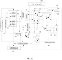
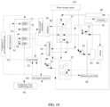
- FIG. 13 is a schematic circulation diagram of a first working condition of the thermal management system provided by the present application.
- the first working condition provided by the present application is the cooling mode.
- the motor and the battery of the vehicle need to be cooled when the vehicle is running.
- the specific control method of the thermal management system includes as follows:
- the flow direction of the cooling liquid in the motor cooling mechanism loop is as follows.
- the cooling liquid flows out of the motor cooling mechanism 80, flows into the first-valve-port m 318, and then flows into the first-valve-port k 317, and flows into the liquid inlet of the radiator 82 through the first-valve-port k 317.
- the cooling liquid flows into the first-valve-port e 314 from the liquid outlet of the radiator 82, flows from the first-valve-port e 314 into the first-valve-port c 313, and then flows out of the first-valve-port c 313 and flows into the motor water pump 23, and flows into the motor cooling mechanism 80 after cyclic supercharging of the motor water pump 23, thereby forming a closed loop.
- the cooling liquid absorbs the heat generated by the motor cooling mechanism 80 and transfers it to the radiator 82, and after heat exchange with the air through the radiator 82, the heat absorbed by the cooling liquid is transferred to the air, thereby realizing the cooling of the motor cooling mechanism 80.
- the fifth first-valve-port f 315 is controlled to be communicated with the sixth first-valve-port h 316 in the first multi-way valve 31, where the fifth first-valve-port f 315 communicates with the liquid outlet of the battery cooling mechanism 83, and the sixth first-valve-port h 316 communicates with the liquid inlet of the heat exchanger 50, and the cooling liquid in the battery cooling mechanism 83 flows into the heat exchanger 50 through the fifth first-valve-port f 315 and the sixth first-valve-port h 316 in turn; the seventh first-valve-port b 312 is controlled to be communicated with the eighth first-valve-port a 311 in the first multi-way valve 31, where the liquid outlet of the heat exchanger 50 communicates with the seventh first-valve-port b 312, and the liquid inlet of the battery cooling mechanism 83 communicates with the eighth first-valve-port a 311; the cooling liquid flowing into the heat exchanger 50 is cooled in the heat exchanger 50, and then
- the flow direction of the cooling liquid in the battery cooling mechanism loop is as follows.
- the cooling liquid flows out of the battery cooling mechanism 83 and is divided into two paths of cooling liquid.
- the cooling liquid flows into the first-valve-port f 315, and then flows into the first-valve-port h 316 and flows out of the first-valve-port h 316; and in the other path, the cooling liquid flows through the controller 81 and then converges with the cooling liquid flowing out of the first-valve-port h 316 to flow into the heat exchanger 50 together, then flows into the first-valve-port b 312 from the heat exchanger 50.
- the cooling liquid flows into the first-valve-port a 311 and flows out of the first-valve-port a 311 into the battery water pump 22, and flows into the battery cooling mechanism 83 after cyclic supercharging of the motor water pump 23, forming a closed loop.
- the cooling liquid absorbs the heat generated by the battery cooling mechanism 83 and the controller 81 and transfers it to the heat exchanger 50.
- heat exchanger 50 heat exchange is performed with the refrigerant, so as to transfer the absorbed heat to the refrigerant, thereby realizing the cooling of battery cooling mechanism 83 and the controller 81.
- a first second-valve-port a 321 is controlled to be in communication with a second second-valve-port c 323 in the second multi-way valve 32, where the first second-valve-port a 321 communicates with the liquid outlet of the heater 84, the second second-valve-port c 323 communicates with the liquid inlet of the warm-air core body 85, and the liquid outlet of the warm-air core body 85 communicates with the liquid inlet of the heater 84; a cooling liquid flowing out of the heater 84 flows into the heater 84 through the first second-valve-ports a 321, the second second-valve-ports c 323, and the warm-air core body 85 in turn.
- the warm air loop is used to heat the cockpit of the vehicle.
- the cooling liquid flows into the second-valve-port a 321 from the liquid outlet of the heater 84, then flows into the second-valve-port c 323 from the second-valve-port a 321, and flows into the warm-air core body 85, and the cooling liquid flows into the heating water pump 21 after flowing out of the warm-air core body 85, and flows into the liquid inlet of the heater 84 after cyclic supercharging of the heating water pump 21, thereby forming a closed loop.
- the heater 84 is mainly used to heat the cooling liquid, and the warm-air core body 85 is disposed in the cockpit for heat exchange.
- the loop is only suitable for the driver to preheat the cockpit in a low temperature environment. When the ambient temperature is higher, the loop is in a state of stopping operation.
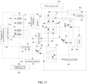
- FIG. 14 is a schematic circulation diagram of a second working condition of the thermal management system provided by the present application.
- the second working condition provided by the present application is the heat dissipation mode of shared radiator.
- the motor cooling mechanism loop and the battery cooling mechanism loop are communicated to each other and share the same radiator for heat dissipation.
- the specific control method of the thermal management system includes the following steps:
- the flow direction of the serial loop composed of the motor cooling mechanism 80 and the battery cooling mechanism 83 is as follows.
- the cooling liquid flows out of the liquid outlet of the motor cooling mechanism 80 and flows into the first-valve-port m 318, then flows into the first-valve-port k 317, and flows into the liquid inlet of the radiator 82 from the first-valve-port k 317, and then flows into the first-valve-port e 314 from the liquid outlet of the radiator 82 after the heat exchange by the radiator 82, then flows into the first-valve-port a 311, and flows into the battery water pump 22 from the first-valve-port a 311, and flows into the battery cooling mechanism 83 after cyclic supercharging of the battery water pump 22.
- the cooling liquid flowing out of the battery cooling mechanism 83 is divided into two paths of cooling liquid.
- the cooling liquid flows into the first-valve-port f 315, then flows into the first-valve-port h 316 and flows out of the first-valve-port h 316; and in the other path, the cooling liquid flows through the controller 81 and then converges with the cooling liquid flowing out of the first-valve-port h 316 to flow into the heat exchanger 50 together, then flows into the first-valve-port b 312 from the heat exchanger 50, further flows into the first-valve-port c 313, flows into the motor water pump 23 from the first-valve-port c 313, and flows into the liquid inlet of the motor cooling mechanism 80 after cyclic supercharging of the motor water pump 23, forming a closed loop.
- the motor cooling mechanism 80, the battery cooling mechanism 83 and the controller 81 are connected in series in the same loop, the heat generated by the three is absorbed by the cooling liquid and transferred to the radiator 82, and the treatment of heat dissipation and cooling is performed by the radiator 82 in a unified manner.
- FIG. 15 is a schematic circulation diagram of a third working condition of the thermal management system provided by the present application.
- the third working condition provided by the present application is the rapid temperature rise mode of the motor cooling mechanism.
- the motor cooling mechanism 80 is rapidly preheated, so that the temperature of the motor cooling mechanism 80 rises to the better working temperature range as soon as possible.
- preheating treatment will also be performed on the battery cooling mechanism 83 and the controller 81, so that the temperature of the both rise to a better working temperature range as soon as possible.
- the specific control method of the thermal management system includes the following steps:
- the flow direction of the motor cooling mechanism loop is as follows.
- the cooling liquid flows into the first-valve-port m 318 from the motor cooling mechanism 80, and then flows through the first-valve-port n 319, the first-valve-port e 314, and the first-valve-port c 313 in turn, flows into the motor water pump 23 from the first-valve-port c 313, and flows into the motor cooling mechanism 80 after cyclic supercharging of the motor water pump 23, forming a closed loop.
- the flow direction of the battery cooling mechanism loop is as follows: the cooling liquid flows out of the battery cooling mechanism 83 and is divided into two paths of cooling liquid. In one path, the cooling liquid flows into the first-valve-port f 315, then flows into the first-valve-port h 316 and flows out of the second-valve-port h 316.
- the cooling liquid flows through the controller 81 and converges with the cooling liquid flowing out of the first-valve-port h 316 to co-flow into the heat exchanger 50, flows into the first-valve-port b 312 from the heat exchanger 50, then flows into the first-valve-port a 311 and flows into the battery water pump 22 from the first-valve-port a 311, and flows into the battery cooling mechanism 83 after cyclic supercharging of the battery water pump 22, forming a closed loop.
- the heat exchanger 50 does not start to work, that is, the heat exchanger 50 does not perform a heat dissipation treatment on the influent cooling liquid, so the heat absorbed by the cooling liquid from the battery cooling mechanism 83 and the controller 81 can be transferred to the battery cooling mechanism 83 and the controller 81 again, thereby reducing the heat loss of the battery cooling mechanism 83 and the controller 81, and enabling the temperature of the battery cooling mechanism 83 and the controller 81 to quickly rise to the better working temperature range.
- the temperature of the cockpit is also low.
- the warm air loop is started to heat the cockpit.
- the operation of loop is closed.
- FIG. 16 is a schematic circulation diagram of a fourth working condition of the thermal management system provided by the present application.
- the fourth working condition provided by the present application is waste heat recovery mode.
- the battery cooling mechanism 83 and the controller 81 are heated by collecting the heat generated by the motor cooling mechanism 80.
- the motor cooling mechanism 80 is started for a period of time, its temperature can quickly rise to the better working temperature range, while the temperatures of the battery cooling mechanism 83 and the controller 81 are still in a lower state, so it is possible to transfer the heat generated by the motor cooling mechanism 80 to the battery cooling mechanism 83 and the controller 81 so that the temperature of both can rise to a better working temperature range as soon as possible.
- the motor cooling mechanism loop and the battery cooling mechanism loop are connected to form a serial loop.
- the specific control method of the thermal management system includes the following steps:
- the flow direction of the serial loop of the motor cooling mechanism 80 and the battery cooling mechanism 83 is as follows: the cooling liquid flows into the first-valve-port m 318 from the motor cooling mechanism 80, flows through the first-valve-port n 319, the first-valve-port e 314 and the first-valve-port a 311 in turn, and flows into the battery water pump 22 through the first-valve-port a 311, and flows into the battery cooling mechanism 83 after cyclic supercharging of the battery water pump 22.
- the cooling liquid flowing out of the battery cooling mechanism 83 is divided into two paths of cooling liquid, in one path, the cooling liquid flows into the first-valve-port f 315, then flows into the first-valve-port h 316 and flows out of the first-valve-port h 316.
- the cooling liquid flows through the controller 81 and then converges with the cooling liquid flowing out of the first-valve-port h 316 to flow into the heat exchanger 50 together, flows into the first-valve-port b 312 from the heat exchanger 50, flows into the first-valve-port c 313 and then flows into the motor water pump 23 from the first-valve-port c 313, and flows into the motor cooling mechanism 80 after cyclic supercharging of the motor water pump 23, forming a closed loop.
- both the radiator 82 and the heat exchanger 50 are in a stopped state, and the heat generated by the motor cooling mechanism 80 is transferred by the cooling liquid to the battery cooling mechanism 83 and the controller 81 to heat them.
- the working state of the warm air loop depends on the level of the environmental problem to decide whether to turn on or not.
- FIG. 17 is a schematic circulation diagram of a fifth working condition of the thermal management system provided by the present application.
- the fifth working condition provided by the present application is that the temperature of motor cooling mechanism 80 rapidly rises, the battery cooling mechanism 83 has no flow request and the controller 81 has a flow request.
- the motor cooling mechanism loop is the same as that in the third working condition, which will not be repeated one by one, and only the battery cooling mechanism loop will be described below.
- the specific flow direction of the battery cooling mechanism loop is as follows: the cooling liquid flows out of the battery cooling mechanism 83 and flows into the controller 81, and then flows into the heat exchanger 50 after flowing out of the controller 81, and then flows into the first-valve-port b 312 from the heat exchanger 50, then flows into the first-valve-port a 311 and flows into the battery water pump 22 from the first-valve-port a 311, and then flows into the battery cooling mechanism 83 after cyclic supercharging of the battery water pump 22, forming a closed loop.
- the controller 81 requires a relatively large flow of cooling fluid during operation, so all the cooling fluid flowing out of the battery cooling mechanism 83 is fed into the controller 81 to meet its working requirements. However, the flow of the cooling liquid flowing through the battery cooling mechanism 83 will not change.
- FIG. 18 is a schematic circulation diagram of a sixth working condition of the thermal management system provided by the present application.
- the sixth working condition provided by the present application is that the motor cooling mechanism 80 needs to be cooled, the battery cooling mechanism 83 has no flow request and the controller 81 has a flow request as well as the degassing mode.
- the circulation direction of the motor cooling mechanism loop is consistent with the circulation mode of the motor cooling mechanism loop under the first working condition.
- the battery cooling mechanism loop is consistent with that under the fifth working condition, so it will be repeated here!
- the degassing mode refers to exhaustion of the air entered the controller 81.
- the mode of the cooling liquid completely flowing into the controller 81 the air inside the controller 81 is discharged from the replenishment port of the water storage region 150, thereby avoiding affecting the operation of the vehicle.
- the warm air loop is also in a stopped state.
- FIG. 19 is a schematic circulation diagram of a seventh working condition of the thermal management system provided by the present application.
- the seventh working condition provided by this application is the large tandem auxiliary degassing mode.
- This working condition is to perform exhaust treatment on the entire thermal management system.
- the motor cooling mechanism loop is connected with the battery cooling mechanism loop to form a large tandem loop.
- the flow direction of the cooling liquid in the large tandem loop is as follow: the cooling liquid flows into the first-valve-port m 318 from the motor cooling mechanism 80, next flows into the first-valve-port k 317, flows into the radiator 82 from the first-valve-port k 317, flows out of the radiator 82 and flows into the first-valve-port e 314, flows into the first-valve-port a 311, flows out of the first-valve-port a 311 and flows into the battery water pump 22, flows into the battery cooling mechanism 83 after cyclic supercharging of the battery water pump 22, flows out of the battery cooling mechanism 83 and all flows into the controller 81, then flows into the heat exchanger 50 after flowing out of the controller 81, then flows into the first-valve-port b 312 after flowing out of the heat exchanger 50, flows into the first-valve-port c 313 and flows into the motor water pump 23 from the first-valve-port c 313, and flows into the motor cooling mechanism 80 after cyclic
- the vehicle In this working condition, the vehicle is at a stopped state, and both the radiator 82 and the heat exchanger 50 are in a stop-working state.
- the radiator 82 is equivalent to a large-capacity gas-liquid separation device, the air in the heat management system is exhausted into the radiator 82 by the cooling liquid, and the air is exhausted by the radiator 82, thereby making the whole system work in a normal cycle.
- the warm air loop is also in a stop-working state.
Landscapes
- Engineering & Computer Science (AREA)
- Mechanical Engineering (AREA)
- Physics & Mathematics (AREA)
- Thermal Sciences (AREA)
- Chemical & Material Sciences (AREA)
- Combustion & Propulsion (AREA)
- Transportation (AREA)
- Air-Conditioning For Vehicles (AREA)
- Cooling, Air Intake And Gas Exhaust, And Fuel Tank Arrangements In Propulsion Units (AREA)
- Cooling Or The Like Of Electrical Apparatus (AREA)
Abstract
Description
- The present application claims priority to
Chinese Patent Application No. 202111137071.2, entitled with "THERMAL MANAGEMENT SYSTEM, VEHICLE, AND THERMAL MANAGEMENT METHOD", filed with the China National Intellectual Property Administration (CNIPA) on September 27 2021 Chinese Patent Application No. 202111138847.2, entitled with "THERMAL MANAGEMENT SYSTEM AND VEHICLE", filed with the CNIPA on September 27 2021 - The present application relates to the technology field of vehicles and, in particular, a thermal management system, a vehicle and a thermal management method.
- With the popularity of new energy vehicles, the importance of vehicle thermal management systems has become increasingly prominent. Compared with traditional fuel vehicles, the thermal management system of new energy vehicles has become more complex and has higher requirements.
- At present, pure electric vehicles usually need to install many thermal management components, such as a water pump, a heat exchanger, a water-cooled condenser, a two-way solenoid valve, a two-way proportional valve and a cooling pipeline, according to the thermal management requirements of the whole vehicle. In order to enhance the range of electric vehicles, it has more and more requirements for the working condition design of the thermal management of the whole vehicle, and the number of components required in the thermal management system also increases accordingly. Due to the scattered arrangement of each component, the space occupied by the components after being installed on the vehicle is larger, and a large number of cooling pipelines need to be used to communicate between the dispersedly installed components to allow the cooling liquid to circulate between components, thereby meeting the thermal management requirements of the whole vehicle.
- However, the use of a large number of cooling pipeline connections increases the length of the cooling pipeline in the entire system, and enlarges the flow resistance of the cooling liquid in the cooling pipeline, which lowers the working efficiency of the thermal management system.
- The present application provides a thermal management system, a vehicle and a thermal management method to solve the problems of using a large number of cooling pipeline connections in the prior art, which increases the length of the cooling pipeline in the entire system, increases the flow resistance of the cooling liquid in the cooling pipeline, and lowers the working efficiency of the thermal management system.
- According to a first aspect of the present application, a thermal management system for a vehicle is provided. The thermal management system includes: a tank assembly, a valve unit, a radiator and a heat exchanger, where the tank assembly includes a shell body and a cover plate, the shell body covers the cover plate and forms an accommodation chamber together with the cover plate and the valve unit is installed on the shell body.
- A plurality of pipelines for liquid circulation is disposed in the accommodation chamber, and the shell body has a plurality of connection ports communicating with the accommodation chamber, a first end of the pipeline communicates with the connection port in one-to-one correspondence, and a second end of the pipeline and a portion of the pipeline are located outside the accommodation chamber.
- The valve unit has a plurality of valve ports, and the valve ports communicate with the connection ports in one-to-one correspondence. The valve unit includes a first multi-way valve and a second multi-way valve, and the plurality of valve ports includes a plurality of first-valve-ports and a plurality of second-valve-ports, the first-valve-ports are located at the first multi-way valve, and the second-valve-ports are located at the second multi-way valve; the radiator and the heat exchanger communicate with different pipelines, respectively.
- According to a second aspect of the present application, a thermal management system for a vehicle is provided. The thermal management system includes: a tank assembly, a pump assembly, and a valve unit. The tank assembly includes a shell body and a cover plate, the shell body covers the cover plate and forms an accommodation chamber together with the cover plate, the pump assembly and the valve unit are each installed on the shell body.
- A plurality of pipelines for liquid circulation is disposed in the accommodation chamber, and the shell body has a plurality of connection ports communicating with the accommodation chamber, a first end of the pipeline communicates with the connection port in one-to-one correspondence, and a second end of the pipeline and a portion of the pipeline are located outside the accommodation chamber.
- The valve unit has a plurality of valve ports, and the valve ports communicate with the connection ports in one-to-one correspondence, and the valve units are configured for controlling a disconnection or connection between each connection port and its corresponding valve ports, so as to control the a disconnection or connection between the pipelines.
- In a possible implementation, in the thermal management system provided by the present application, a side of the shell body facing away from the cover plate has a first installation region and a second installation region, and the plurality of connection ports include a plurality of first connection ports and a plurality of second connection ports, the first connection ports are located in the first installation region, and the second connection ports are located in the second installation region.
- The valve unit includes a first multi-way valve and a second multi-way valve, and a plurality of valve ports include a plurality of first-valve-ports and a plurality of second-valve-ports, the first-valve-ports are located at the first multi-way valve, and the second-valve-ports are located at the second multi-way valve.
- The first multi-way valve is connected in the first installation region, and the first connection ports communicate with the first-valve-ports in one-to-one correspondence; the second multi-way valve is connected in the second installation region, and the second connection ports communicate with the second-valve-ports in one-to-one correspondence.
- In a possible implementation, in the thermal management system provided by the present application, a plurality of pipelines include a plurality of first pipelines, each first pipeline includes two first sub-pipelines, and a first end of one first sub-pipeline in each first pipeline corresponds to the first installation region, a second end of the one first sub-pipeline in each first pipeline is configured for communicating with a water outlet pipe of same component in a vehicle; a first end of the other first sub-pipeline in each first pipeline corresponds to the first installation region, and a second end of the other first sub-pipeline in the each first pipeline is configured for communicating with a water inlet pipe of same component in the vehicle.
- The component includes at least one of a radiator, a battery cooler, or a motor cooler.
- In a possible implementation, in the thermal management system provided by the present application, a plurality of pipelines include a second pipeline and a third pipeline, a first end of the second pipeline corresponds to the first installation region, and a first end of the third pipeline corresponds to the second installation region.
- The second pipeline includes two second sub-pipelines, one second sub-pipeline in the second pipeline is configured for communicating with a water outlet pipe of a warm-air core body in a vehicle, and the other second sub-pipeline in the second pipeline communicates with a water inlet pipe of a heater in the vehicle.
- The third pipeline includes two third sub-pipelines, one third sub-pipeline in the third pipeline is configured for communicating with a water outlet pipe of the heater, and the other third sub-pipeline in the third pipeline communicates with a water inlet pipe of the warm-air core body.
- In a possible implementation, in the thermal management system provided by the present application, a water storage region is disposed in the accommodation chamber, and the water storage region is located above each pipeline.
- The water storage region has a liquid replenishment port communicating with the pipeline.
- In a possible implementation, the thermal management system provided by the present application further includes a water-cooled condenser and a heat exchanger, the water-cooled condenser is installed on a side of the shell body facing away from the cover plate and has a first inlet and a first outlet, the heat exchanger is installed on a side of the cover plate facing away from the shell body and has a second inlet and a second outlet.
- The plurality of pipelines include two fourth pipelines, where a first end of one fourth pipeline corresponds to the second installation region and the one fourth pipeline communicates with the first inlet; and a first end of the other fourth pipeline corresponds to the first installation region, and the other fourth pipeline communicates with the first outlet.
- The plurality of pipelines include two fifth pipelines, where first ends of the fifth pipelines each correspond to the first installation region, one fifth pipeline communicates with the second outlet, and the other fifth pipeline communicates with the second inlet.
- In a possible implementation, the thermal management system provided by the present application further includes a gas-liquid separator, the cover plate has an installation part that is located outside the accommodation chamber, and the gas-liquid separator is installed on a side of the installation part facing the shell body, and is adjacent to the water-cooled condenser.
- A refrigerant inlet of the gas-liquid separator communicates with a refrigerant outlet of the heat exchanger, and the gas-liquid separator is also configured for communicating with an outlet of an air-conditioning unit evaporator of the vehicle.
- In a possible implementation, the thermal management system provided by the present application further includes an integration valve of air conditioner, which is installed on a side of the installation part facing away from the shell body, the integration valve of air conditioner is adjacent to the heat exchanger, and the integration valve of air conditioner communicates with a refrigerant inlet of the water-cooled condenser and a refrigerant inlet of the heat exchanger, respectively.
- A refrigerant outlet of the water-cooled condenser communicates with the integration valve of air conditioner through a coaxial pipe.
- A refrigerant outlet of the gas-liquid separator communicates with a suction port of the compressor of the vehicle through a coaxial pipe.
- The coaxial pipe is also configured for communicating with an outlet of the condenser inside air-conditioning unit of the vehicle.
- The integration valve of air conditioner is configured for communicating with an inlet of the condenser inside air-conditioning unit, and is also configured for communicating with an exhaust port of the compressor.
- In a possible implementation, in the thermal management system provided by this application, the pump assembly includes a heating water pump, a battery water pump, and a motor water pump. The heating water pump, the battery water pump, and the motor water pump are each installed on a side of the shell body facing away from the cover plate. The heating water pump, the battery water pump and the motor water pump are connected with different pipelines located outside the accommodation chamber, respectively.
- According to a third aspect of the present application, a vehicle is provided, including a vehicle body and a thermal management system installed on the vehicle body.
- According to a fourth aspect of the present application, a thermal management method is provided, which uses a thermal management system, the method includes the following steps:
- controlling communication between a first first-valve-port and a second first-valve-port in the first multi-way valve, where the first first-valve-port communicates with a liquid outlet of a motor cooling mechanism, the second first-valve-port communicates with a liquid inlet of the radiator, and a cooling liquid in the motor cooling mechanism flows into the radiator through the first first-valve-port and the second first-valve-port in turn;
- controlling communication between a third first-valve-port and a fourth first-valve-port in the first multi-way valve, where a liquid outlet of the radiator communicates with the third first-valve-port, the fourth first-valve-port communicates with a liquid inlet of the motor cooling mechanism, and the cooling liquid flowing into the radiator flows into the motor cooling mechanism through the third first-valve-port and the fourth first-valve-port in turn after being cooled in the radiator.
- In a possible implementation, the thermal management method provided by the present application further includes the following steps:
- controlling communication between a fifth first-valve-port and a sixth first-valve-port in the first multi-way valve, where the fifth first-valve-port communicates with a liquid outlet of a battery cooling mechanism, and the sixth first-valve-port communicates with a liquid inlet of the heat exchanger, and a cooling liquid in the battery cooling mechanism flows into the heat exchanger through the fifth first-valve-port and the sixth first-valve-port in turn;
- controlling communication between a seventh first-valve-port and an eighth first-valve-port in the first multi-way valve, where a liquid outlet of the heat exchanger communicates with the seventh first-valve-port, and the liquid inlet of the battery cooling mechanism communicates with the eighth first-valve-port, the cooling liquid flowing into the heat exchanger flows into the battery cooling mechanism through the seventh first-valve-port and the eighth first-valve-port in turn after being cooled in the heat exchanger.
- In a possible implementation, the thermal management method provided by the present application further includes the following steps:
- controlling communication between the third first-valve-port and the eighth first-valve-port in the first multi-way valve, where a cooling liquid flowing into the radiator flows into the battery cooling mechanism through the third first-valve-port and the eighth first-valve-port in turn after being cooled in the radiator;
- controlling communication between the seventh first-valve-port and the fourth first-valve-port in the first multi-way valve, where the cooling liquid flowing into the heat exchanger flows into the motor cooling mechanism through the seventh first-valve-port and the fourth first-valve-port in turn after being cooled in the heat exchanger.
- In a possible implementation, the thermal management method provided by the present application further includes the following steps:
- controlling communication between the first first-valve-port and a ninth first-valve-port in the first multi-way valve, where the ninth first-valve-port communicates with the third first-valve-port, and the third first-valve-port communicates with the fourth first-valve-port, and the cooling liquid in the motor cooling mechanism flows into the motor cooling mechanism through the first first-valve-port, the ninth first-valve-port, the third first-valve-port and the fourth first-valve-port in turn;
- controlling communication between the seventh first-valve-port and the eighth first-valve-port in the first multi-way valve, where the cooling liquid flowing out of the heat exchanger flows into the battery cooling mechanism through the seventh first-valve-port and the eighth first-valve-port in turn.
- In a possible implementation, the thermal management method provided by the present application further includes the following steps:
- controlling communication between the third first-valve-port and the eighth first-valve-port in the first multi-way valve, where the cooling liquid in the motor cooling mechanism flows into the battery cooling mechanism through the first first-valve-port, the ninth first-valve-port, the third first-valve-port and the eighth first-valve-port in turn;
- controlling communication between the seventh first-valve-port and the fourth first-valve-port in the first multi-way valve, where the cooling liquid flowing out of the heat exchanger flows into the motor cooling mechanism through the seventh first-valve-port and the fourth first-valve-port in turn.
- In a possible implementation, the thermal management method provided by the present application further includes the following steps:
a part of the cooling liquid flowing out of the battery cooling mechanism flows into a controller, and the cooling liquid flowing out of the controller flows into the heat exchanger. - In a possible implementation, in the thermal management method provided by the present application, the method further includes the following steps:
controlling communication between the seventh first-valve-port and the eighth first-valve-port in the first multi-way valve, where the cooling liquid in the battery cooling mechanism flows into the heat exchanger through the controller, and the cooling liquid flowing out of the heat exchanger flows into the battery cooling mechanism through the seventh first-valve-port and the eighth first-valve-port. - In a possible implementation, in the thermal management method provided by the present application, the method further includes the following steps:
- controlling communication between a first second-valve-port and a second second-valve-port in the second multi-way valve, where the first second-valve-port communicates with a liquid outlet of the heater, the second second-valve-port communicates with a liquid inlet of the warm-air core body, and the liquid outlet of the warm-air core body communicates with a liquid inlet of the heater;
- the cooling liquid flowing out of the heater flows into the heater through the first first-valve-port, the second first-valve-port and the warm-air core body in turn.
- The present application provides a thermal management system, a vehicle, and a thermal management method. The thermal management system includes: a tank assembly and a valve unit, the tank assembly includes a shell body and a cover plate, the shell body covers the cover plate and forms an accommodation chamber together with the cover plate, the valve unit is installed on the shell body; a plurality of pipelines for liquid circulation is disposed in the accommodation chamber, the shell body has a plurality of connection ports communicating with the accommodation chamber, the first ends of the pipelines communicate with the connection ports in one-to-one correspondence, and the second ends of the pipelines and a portion of the pipeline are located outside the accommodation chamber; the valve unit has a plurality of valve ports, the valve ports communicate with the connection ports in one-to-one correspondence. By setting up the integrated tank assembly, each components of the thermal management system are integrated to install on the shell body and cover plate of the tank assembly, and the pipelines for cooling liquid circulation are integrated inside the accommodation chamber, thereby realizing the integration of the scattered installation components in the prior art into a module assembly. The highly integrated thermal management system not only effectively saves the installation space, but also saves a lot of pipelines, thereby reducing the flow resistance in the pipelines and improving the working efficiency of thermal management. It solves the problems of using a large number of cooling pipeline connections in the prior art, which leads to the increased length of the cooling pipeline in the entire system, increased flow resistance of the cooling liquid in the cooling pipeline, and lower working efficiency of the thermal management system.
- To illustrate the technical solutions in embodiments of the present application or the prior art more clearly, the following briefly introduces the accompanying drawings required for describing the embodiments or the prior art. Apparently, the accompanying drawings in the following description are some embodiments of the present application, and persons of ordinary skill in the art may still derive other drawings from these accompanying drawings without paying creative effort.
-
FIG. 1 is a structural schematic diagram of a thermal management system provided by the present application. -
FIG. 2 is another structural schematic diagram of the thermal management system provided by the present application. -
FIG. 3 is a structural schematic diagram of a tank assembly in the thermal management system provided by the present application. -
FIG. 4 is another structural schematic diagram of the tank assembly in the thermal management system provided by the present application. -
FIG. 5 is an enlarged schematic diagram at A inFIG. 3 . -
FIG. 6 is an enlarged schematic diagram at B inFIG. 3 . -
FIG. 7 is a structural schematic diagram of a first multi-way valve in the thermal management system provided by the present application. -
FIG. 8 is a structural schematic diagram of a second multi-way valve in the thermal management system provided by the present application. -
FIG. 9 is an enlarged schematic diagram at C inFIG. 4 . -
FIG. 10 is a schematic circulation diagram of the thermal management system provided by the present application. -
FIG. 11 is an enlarged schematic diagram at D inFIG. 10 . -
FIG. 12 is an enlarged schematic diagram at E inFIG. 10 . -
FIG. 13 is a schematic circulation diagram of a first working condition of the thermal management system provided by the present application. -
FIG. 14 is a schematic circulation diagram of a second working condition of the thermal management system provided by the present application. -
FIG. 15 is a schematic circulation diagram of a third working condition of the thermal management system provided by the present application. -
FIG. 16 is a schematic circulation diagram of a fourth working condition of the thermal management system provided by the present application. -
FIG. 17 is a schematic circulation diagram of a fifth working condition of the thermal management system provided by the present application. -
FIG. 18 is a schematic circulation diagram of a sixth working condition of the thermal management system provided by the present application. -
FIG. 19 is a schematic circulation diagram of a seventh working condition of the thermal management system provided by the present application. - Description of reference numbers:
- in each schematic circulation diagram, the combination of solid line and arrow represents the flow direction of cooling liquid, the combination of dotted line and arrow represents the flow direction of refrigerant, and the combination of double-dot dash line and arrow represents the flow direction of cooling liquid replenishment;
- 10-tank assembly; 11-shell body; 12-cover plate;
- 110-connection port; 111-first installation region; 112-second installation region; 113-first surface; 114-first side; 120-installation part; 130-pipeline; 131-water inlet pipe of radiator; 132-water outlet pipe of radiator; 133-water inlet pipe of motor cooling mechanism; 134-water outlet pipe of motor cooling mechanism; 135-water inlet pipe of battery cooling mechanism; 136-water outlet pipe of battery cooling mechanism; 137-water inlet pipe of heater; 138-water outlet pipe of heater; 139-water inlet pipe of warm-air core body; 140-water outlet pipe of warm-air core body; 150-water storage region; 151-injection port;
- 1111-first connection port a; 1112-first connection port b, 1113-first connection port c; 1114-first connection port e; 1115-first connection port f; 1116-first connection port h; 1117-first connection port k; 1118-first connection port m; 1119-first connection port n; 1121-second connection port a; 1122-second connection port b; 1123-second connection port c; 1124-second connection port e; 1125-second connection port f;
- 20-pump assembly; 21-heating water pump; 22-battery water pump; 23-motor water pump;
- 30-valve unit; 31-first multi-way valve; 32-second multi-way valve;
- 311-first-valve-port a; 312-first-valve-port b; 313-first-valve-port c; 314-first-valve-port e; 315-first-valve-port f; 316-first-valve-port h; 317-first-valve-port k; 318-first-valve-port m; 319-first-valve-port n; 321-second-valve-port a; 322-second-valve-port b; 323-second-valve-port c; 324-second-valve-port e; 325-second-valve-port f;
- 40-water-cooled condenser;
- 50-heat exchanger;
- 60-gas-liquid separator;
- 70-integration valve of air conditioner; 71-first switch valve; 72-second switch valve; 73-first expansion valve; 74-second expansion valve;
- 80-motor cooling mechanism; 81-controller; 82-radiator; 83-battery cooling mechanism; 84-heater; 85-warm-air core body;
- 90-evaporator of air-conditioning unit; 91-compressor; 92-condenser of air-conditioning unit; 93-coaxial pipe.
- To make the objectives, technical solutions, and advantages of embodiments of the present application clearer, the following clearly and comprehensively describes the technical solutions in embodiments of the present application with reference to the accompanying drawings in embodiments of the present application. Apparently, the described embodiments are merely a part rather than all embodiments of the present application. Based on the embodiments in the present application, all other embodiments obtained by persons of ordinary skill in the art without paying creative efforts fall within the protection scope of the present application.
- In the description of the present application, it should be noted that, unless otherwise clearly stipulated and limited, the terms "installation", "connecting" and "connection" should be understood in a broad sense, for example, it can be fixed connection, or indirect connection through an intermediate, which may be the communication inside two elements or the interaction relationship between two elements. For persons of ordinary skill in the art, the specific meanings of the aforementioned terms in the present application can be understood according to specific situations.
- In the description of the present application, it is can be understand that the orientation or positional relationship indicated by the terms "upper", "lower", "front", "rear", "vertical", "horizontal", "top", "bottom", "inside", "outside" and so on is based on the orientation or positional relationship shown in the drawings, and is only for the convenience of describing the present application and simplifying the description, rather than indicating or implying that the referred device or element must have a specific orientation, and construct and operate in a particular orientation, and therefore it should not be understood as limiting the application.
- The terms "first", "second" and "third" (if any) in the description and claims of the present application and the aforementioned accompanying drawings are used to distinguish similar objects and not necessarily to describe a specific order or priority. It should be understood that the data used in this way are interchangeable under appropriate circumstances such that the embodiments of the present application described herein can, for example, be practiced in sequences other than those illustrated or described herein.
- In addition, the terms "comprise" and "having", as well as any variations thereof, are intended to cover a non-exclusive inclusion. For example, a process, a method, a system, a product or a maintenance tool comprising a series of steps or units need not be limited to the expressly listed the steps or units, instead, other steps or elements not explicitly listed or inherent to the process, method, product or maintenance tool may be included.
- With the popularity of new energy vehicles, the importance of vehicle thermal management systems has become increasingly prominent. Compared with traditional fuel vehicles, the thermal management system of new energy vehicles becomes more complex and has higher requirements.
- According to the thermal management requirements of the whole vehicle, pure electric vehicles usually need to install many thermal management components, such as: an expansion water pump, a motor water pump, a battery water pump, a warm air water pump, a heat exchanger, a water-cooled condenser, a water temperature sensor, a four-way solenoid valve, a three-way solenoid valve, a two-way solenoid valve, a two-way proportional valve, a three-way proportional valve, a cooling connection pipeline, an air conditioner gas-liquid separator, an air conditioner EXV valve, an air conditioner SOV valve, an air conditioner connection pipeline, etc. At present, in order to further enhance the cruising range of electric vehicles, there are more and more requirements for the design of working conditions for the thermal management of the whole vehicle, and the number of components requiring the thermal management also increases accordingly. Due to the scattered arrangement of each component in the thermal management system, the thermal management system will occupy a large installation space in the vehicle, and the scattered components need to use a large number of cooling pipelines and circulate pipelines for communication between them, thereby meeting the vehicle's demand for the thermal management of the components.
- However, the use of a large number of cooling pipeline connections increases the length of the cooling pipeline in the entire system, increases the flow resistance of the cooling liquid in the cooling pipeline, and lowers the working efficiency of the thermal management system.
- Based on this, the present application provides a thermal management system, a vehicle and a thermal management method. Through the integrated design of parts and components in the thermal management system of the vehicle, thereby saving the length of the pipelines in the thermal management system, and enhancing the working efficiency of the thermal management system.
-
FIG. 1 is a structural schematic diagram of a thermal management system provided by the present application,FIG. 2 is another structural schematic diagram of the thermal management system provided by the present application,FIG. 3 is a structural schematic diagram of the tank assembly in the thermal management system provided by the present application, andFIG. 4 is another structural schematic diagram of the tank assembly in the thermal management system provided by the present application. - As shown in
FIG. 1 andFIG. 2 , the thermal management system provided by the embodiment of the present application includes: atank assembly 10, apump assembly 20, and avalve unit 30. As shown inFIG. 3 andFIG. 4 , thetank assembly 10 includes ashell body 11 and acover plate 12. Theshell body 11 covers thecover plate 12 and forms an accommodation chamber (not shown in the figure) together with thecover plate 12. Thepump assembly 20 and thevalve unit 30 are installed on theshell body 11, respectively; the accommodation chamber is internally provided with a plurality ofpipelines 130 for liquid circulation, and theshell body 11 has a plurality ofconnection ports 110 in communication with the accommodation chamber. A first end of thepipeline 130 communicates with theconnection port 110 in one-to-one correspondence, and a second end of thepipeline 130 and a portion of thepipeline 130 are located outside the accommodation chamber; thevalve unit 30 has a plurality of valve ports (not shown in the figure), and the valve ports communicate with theconnection ports 110 in one-to-one correspondence. Thevalve unit 30 is used for controlling the disconnection or connection between theconnection port 110 and the valve port corresponding to theconnection port 110, thereby controlling the disconnection or connection between the pipelines. - The
tank assembly 10 is the core component of the thermal management system, and it has multiple functions. Thetank assembly 10 can not only provide cooling liquid for cooling and reducing temperature to each component in the thermal management system, but also provide fixed support to each part and component, so as to integrate the dispersed components into an integrated thermal management module, so that an arrangement of respective components is more compact, thereby reducing the installation space of the thermal management system on the vehicle body. - Continuing to refer to
FIG. 3 andFIG. 4 , thetank assembly 10 includes ashell body 11 and acover plate 12. Theshell body 11 has afirst surface 113 and a second surface (not shown in the figure) opposite to thefirst surface 113, the second surface of theshell body 11 is covered with thecover plate 12, and theshell body 11 is connected with thecover plate 12 by a hot plate welding process to form the accommodation chamber together with thecover plate 12. - Continuing to refer to
FIG. 1 andFIG. 3 , thepump assembly 20 and thevalve unit 30 are each fixedly installed on thefirst surface 113 of theshell body 11. - Continuing to refer to
FIG. 3 andFIG. 4 , a plurality ofpipelines 130 for the circulation of the cooling liquid are provided inside the accommodation chamber of thetank assembly 10, and thepipelines 130 are used for communicating with various components in the thermal management system and delivering cooling liquid to the corresponding components. A plurality ofconnection ports 110 are disposed in thefirst surface 113 of theshell body 11, and eachconnection port 110 communicates with the accommodation chamber. A first end of thepipeline 130 communicates with theconnection port 110 in one-to-one correspondence, a second end of thepipeline 130 is located outside the accommodation chamber with a portion of thepipeline 130 after protruding from the accommodation chamber, and the second end of thepipeline 130 is used for communicating with the component installed on theshell body 11 to deliver the cooling liquid. - In the present application, after various parts and components in the thermal management system are integrally installed on the
shell body 11, the overall arrangement of the thermal management system becomes more compact, and the distance between various components also greatly reduced. Furthermore, setting thepipelines 130 for communicating between various components to be inside the accommodation chamber, may not only optimize the spatial arrangement of the overall system, but also greatly shorten the total length of thepipeline 130, thereby effectively reducing the internal resistance of thepipeline 130, and improving the working efficiency of the thermal management system. - The
valve unit 30 is provided with a plurality of valve ports, which are communicated with theconnection ports 110 in one-to-one correspondence. Eachpipeline 130 communicates with thevalve unit 30, and the cooling liquid flows into various components after passing through thevalve unit 30. Thevalve unit 30 is configured for controlling the disconnection or connection between theconnection port 110 and the corresponding valve port communicating with theconnection port 110, thereby controlling the disconnection or connection between thepipelines 130 wherevarious connection ports 110 are located, and then controlling the flow rate of the cooling liquid input to the components connected tovarious pipelines 130. - The
valve unit 30 and thepipelines 130, which are installed in the thermal management system, are connected in series to form closed cooling loops. The opening and closing of different cooling loops is controlled by thevalve unit 30, thereby meeting the requirements of various components for cooling liquid and improving the working efficiency of the overall thermal management system. - In the present application, by setting up the integrated
tank assembly 10, each component in the thermal management system is integrally installed on theshell body 11 and thecover plate 12 in thetank assembly 10, and thepipeline 130 for cooling liquid circulation is integrated inside the accommodation chamber, thereby realizing the integration of the scattered installation components in the prior art into a module assembly. The highly integrated thermal management system not only effectively saves the installation space and unifies the external connection ports of thepipelines 130 to make the arrangement of thepipelines 130 more compact, but also saves a large number ofpipelines 130, reduces the flow resistance in thepipelines 130 and improves the working efficiency of thermal management. It solves the problems of using a large number of cooling pipeline connections in the prior art, which leads to the increased length of the cooling pipeline in the entire system, increased flow resistance of the cooling liquid in the cooling pipeline, and lower working efficiency of the thermal management system. - Continuing to refer to
FIG. 3 , a side of theshell body 11 facing away from thecover plate 12 has afirst installation region 111 and asecond installation region 112, a plurality ofconnection ports 110 includes a plurality of first connection ports (not shown in the figure) and a plurality of second connection ports (not shown in the figure). The first connection port is located in thefirst installation region 111, and the second connection port is located in thesecond installation region 112. The side of theshell body 11 facing away from thecover plate 12 is thefirst surface 113 of theshell body 11, and thefirst surface 113 is provided with afirst installation region 111 and asecond installation region 112 for installing a valve assembly. -
FIG. 5 is an enlarged schematic diagram at A inFIG. 3 , andFIG. 6 is an enlarged schematic diagram at B inFIG. 3 . - As shown in
FIG. 3 ,FIG. 5 andFIG. 6 , nine first connection ports are provided in thefirst installation region 111, which are: a first connection port a 1111, a firstconnection port b 1112, a firstconnection port c 1113, a firstconnection port e 1114, a first connection port f 1115, a firstconnection port h 1116, a firstconnection port k 1117, a firstconnection port m 1118, and a firstconnection port n 1119, respectively. The five second connection ports are provided in thesecond installation region 112, which are: a second connection port a 1121, a secondconnection port b 1122, a secondconnection port c 1123, a second connection port e 1124, and a second connection port f 1125, respectively. -
FIG. 7 is a structural schematic diagram of a first multi-way valve in the thermal management system provided by the present application,FIG. 8 is a structural schematic diagram of a second multi-way valve in the thermal management system provided by the present application, andFIG. 9 is an enlarged schematic diagram at C inFIG. 4 . - As shown in
FIG. 1 ,FIG. 7 andFIG. 8 , thevalve unit 30 includes a firstmulti-way valve 31 and a secondmulti-way valve 32, and the plurality of valve ports includes a plurality of first-valve-ports (not shown in the figure) and a plurality of second-valve-ports (not shown in the figure), where, the first-valve-ports are located on the firstmulti-way valve 31, and the second-valve-ports are located on the secondmulti-way valve 32. - Specifically, the first
multi-way valve 31 includes a valve seat (not shown in the figure) and a valve core (not shown in the figure) rotatably disposed in the valve seat. The valve core has a plurality of rotating positions. The valve seat is provided with the plurality of first-valve-ports, and the valve core is provided with conduction structure groups respectively corresponding to various first-valve-ports. Each conduction structure group includes a plurality of conduction structures disposed along the circumferential direction; and the conduction unit group is configured as follows: when the valve core rotates to different rotating positions, different conduction structures in the conduction unit group cooperate with corresponding first-valve-ports, so that the first-valve-ports form different conduction states. - The valve core is rotatably disposed on the valve seat, and the valve seat is provided with a plurality of first-valve-ports. The conduction structure group corresponding to the first-valve-port is disposed on the valve core, and further includes a plurality of conduction structures disposed along the circumferential direction. When the valve core rotates to different rotation positions, different first-valve-ports form different conduction states. Only one valve core is required.
- The first
multi-way valve 31 may be a nine-way solenoid valve configured for controlling the disconnection or connection of eachpipeline 130 connected to it. The nine-way solenoid valve is provided with nine first-valve-ports, which are: a first-valve-port a 311, a first-valve-port b 312, a first-valve-port c 313, a first-valve-port e 314, a first-valve-port f 315, a first-valve-port h 316, a first-valve-port k 317, a first-valve-port m 318, a first-valve-port n 319, respectively. - The second
multi-way valve 32 includes a valve seat, a first valve core (not shown in the figure), a second valve core (not shown in the figure) and a driving device (not shown in the figure). The driving device is connected to the first valve core in a transmission manner; the first valve core is provided with a first matching structure, and the second valve core is provided with a second matching structure matching with the first matching structure. There is a first mating state and a second mating state between the first matching structure and the second matching structure, where, in the first mating state, the first valve core rotates independently, and the second valve core remains stationary; and in the second mating state, the first valve core drives the second valve core to rotate synchronously. - The valve seat is provided with a plurality of second-valve-ports corresponding to the first valve core, and the valve core is provided with a first conduction structure, and the first conduction structure is configured for communicating at least two second-valve-ports when the first valve cores turn to a first predetermined position. The valve seat is provided with a plurality of second-valve-ports corresponding to the second valve, and the second valve core is provided with a second conduction structure, and the second conduction structure is configured for communicating at least two second-valve-ports when the two valve cores turn to the second predetermined position.
- The driving device is connected with the first valve core in a transmission manner. When the first valve core rotates, the first matching structure of the first valve core can drive the second valve core to rotate by the second matching structure. In this way, the first valve core can rotate independently, and the flow rate of the first valve core may be adjusted by changing the corresponding angle between the first-valve-port and the first conducting structure. When the first valve core rotates, it drives the second spool to rotate; and by changing the corresponding angle between the second-valve-port and the second conduction structure, the flow rate of the second valve core may be adjusted, and the first-valve-port rotates to the original position again, without changing the flow of the first valve core. Only one drive device is required to drive and control the first valve core and the second valve core.
- The driving device includes a motor (not shown in the figure) and a gear set (not shown in the figure) connected to the motor in a transmission manner, and the gear set is connected to the first valve core in a transmission manner. A worm (not shown in the figure) is disposed on the motor shaft. The gear set includes a first worm gear cooperating with the worm, a second worm gear engaged with the first worm gear, a third worm gear engaged with the second worm gear, a first gear connected to the bottom of the third worm gear, and a second gear engaged with the first gear. The central axes of the first worm gear, the second worm gear, the third worm gear, the first gear and the second gear in the gear set are parallel to each other and are all disposed along the vertical direction, and the central axis of the first worm and the central axis of the first worm gear are perpendicular to each other. The worm disposed on the motor shaft rotates and drives the first valve core to rotate through the transmission of the gear set, thereby ensuring the stability of transmission.
- The type of the motor is not limited, and for control simplicity and high precision, preferably, the motor is a stepper motor or a servo motor.
- The second
multi-way valve 32 is a five-way solenoid valve, and the five-way solenoid valve is configured for controlling the opening size ofvarious pipelines 130 connected thereto, thereby controlling the flow rate of the cooling liquid flowing through thepipelines 130. The five-way solenoid valve is provided with five second-valve-ports, which are: a second-valve-port a 321, a second-valve-port b 322, a second-valve-port c 323, a second-valve-port e 324, and a second-valve-port f 325, respectively. - Continuing to refer to
FIG. 1 andFIG. 3 , the firstmulti-way valve 31 is connected in thefirst installation region 111, and the first-valve-port communicates with the first connection port in one-to-one correspondence. The secondmulti-way valve 32 is connected in thesecond installation region 112, and the second-valve-port communicates with the second connection port in one-to-one correspondence. After the firstmulti-way valve 31 is installed inside thefirst installation region 111 on thefirst surface 113 of theshell body 11, each first-valve-port is in one-to-one correspondence with and communicated with each first connection port each other, where the first-valve-port a 311 communicates with the first connection port a 1111 correspondingly, the first-valve-port b 312 communicates with the firstconnection port b 1112 correspondingly, the first-valve-port c 313 communicates with the firstconnection port c 1113 correspondingly, the first-valve-port e 314 communicates with the firstconnection port e 1114 correspondingly, and the first-valve-port f 315 communicates with the first connection port f 1115 correspondingly, the first-valve-port h 316 communicates with the firstconnection port h 1116 correspondingly, the first-valve-port k 317 communicates with the firstconnection port k 1117 correspondingly, the first-valve-port m 318 communicates with the first connection port m 1118 correspondingly, and the first-valve-port n 319 communicates with the firstconnection port h 1119 correspondingly. After the secondmulti-way valve 32 is installed in thesecond installation region 112 on thefirst surface 113 of theshell body 11, each second-valve-port is in one-to-one correspondence with and communicated with each second connection port each other, where the second-valve-port a 321 communicates with the second connection port a 1121 correspondingly, the second-valve-port b 322 communicates with the secondconnection port b 1122 correspondingly, the second-valve-port c 323 communicates with the secondconnection port c 1123 correspondingly, the second-valve-port e 324 communicates with the second connection port e 1124 correspondingly, and the second-valve-port f 325 communicates with the second connection port f 1125 correspondingly. -
FIG. 10 is a schematic circulation diagram of the thermal management system provided by the present application. - As shown in
FIG. 2 ,FIG. 4 andFIG. 10 , the plurality ofpipelines 130 includes a plurality of first pipelines (not shown in the figure), each first pipeline including two first sub-pipelines (not shown in the figure). A first end of one first sub-pipeline in each first pipeline corresponds to thefirst installation region 111, and a second end of the one first sub-pipeline in each first pipeline is configured for communicating with the water outlet pipe of the same component in the vehicle. A first end of the other first sub-pipeline in each first pipeline corresponds to thefirst installation region 111, a second end of the other first sub-pipeline in each first pipeline is configured for communicating with the water inlet pipe of the same component in the vehicle. The component includes at least one of aradiator 82, a battery cooling mechanism (referring to: a battery pack heat dissipating device, hereinafter abbreviated as: a battery cooling mechanism) 83, or a motor cooling mechanism (referring to: a motor heat dissipating device, hereinafter abbreviated as: motor cooling mechanism) 80. - In a possible implementation, in order to make the cooling liquid loops of various components of the vehicle independent from each other, and avoid interference phenomenon, the
pipeline 130 disposed in the accommodation chamber includes a plurality of first pipelines, each first pipeline includes two first sub-pipelines, and the two first sub-pipelines are connected by the firstmulti-way valve 31 to form a first pipeline for the flow of cooling liquid. - Specifically, a first end of one first sub-pipeline in each first pipeline corresponds to and communicates with the first connection port in the
first installation region 111, and a second end of the one first sub-pipeline in each first pipeline is configured for communicating with the water outlet pipe of the same component in the vehicle, and the cooling liquid flowing out of the component flows into the firstmulti-way valve 31 after passing through the first sub-pipeline. A first end of the other first sub-pipeline in each first pipeline corresponds to and communicates with the first connection port in thefirst installation region 111, and a second end of the other first sub-pipeline in each first pipeline is configured for communicating with the water inlet pipe of the same component in the vehicle, and the cooling liquid flowing out of the firstmulti-way valve 31 flows into the component after passing through the first sub-pipeline. The first ends of the two first sub-pipelines are connected through the firstmulti-way valve 31 to form the first pipeline, and then the first pipeline is communicated with the water inlet pipe and the water outlet pipe of the same component in the vehicle to form a closed cooling loop. The opening and closing state of the cooling loop is controlled by the firstmulti-way valve 31, so as to provide the cooling liquid for the components in the vehicle. - The components in the vehicle where the circulation of the cooling liquid is usually present mainly include the
radiator 82, thebattery cooling mechanism 83, themotor cooling mechanism 80 and other components. Among them, thebattery cooling mechanism 83 is a cooling mechanism disposed on the battery pack of the vehicle, which is mainly attached to the battery pack for exchanging heat with the battery pack. After the cooling liquid flow through the cooling mechanism, it can absorb and take away the heat generated from the battery pack, so that the battery pack is in a range of better temperature during operation. - The
motor cooling mechanism 80 is a cooling mechanism disposed on the motor of the vehicle, which is attached to the outer shell body of the motor for heat exchange. When the vehicle's motor starts to work, it will generate a large amount of heat. If the heat cannot be released in time, it will affect the working performance of the vehicle's motor. Therefore, after the cooling liquid flows through the cooling device on the vehicle motor, it can absorb and take away the heat generated from the motor, so that the vehicle's motor is in a range of better temperature during operation. - The
radiator 82 is a device that is disposed in the vehicle for exchanging heat with the air. After the cooling liquid brings the absorbed heat to theradiator 82, theradiator 82 exchanges heat with the air so that it can transfer the heat to the air, thereby ensuring the normal operation of the vehicle. - As shown in
FIG. 3 ,FIG. 4 andFIG. 9 , second ends of the plurality of first sub-pipelines protrude from the accommodation chamber out of theshell body 11 to form a plurality of connection ports communicating with related components in the vehicle. Specifically, a water inlet pipe ofradiator 131, a water outlet pipe ofradiator 132, a water inlet pipe of motor cooling mechanism 133, and a water inlet pipe ofbattery cooling mechanism 135 are provided on thefirst surface 113 of theshell body 11; and a water outlet pipe ofmotor cooling mechanism 134 and a water outlet pipe ofbattery cooling mechanism 136 are provided on afirst side 114 of theshell body 11. - The liquid inlet and the liquid outlet of the
radiator 82 of the vehicle are communicated with the water inlet pipe ofradiator 131 and the water outlet pipe ofradiator 132, respectively; and the liquid inlet and the liquid outlet of thebattery cooling mechanism 83 are communicated with the water inlet pipe ofbattery cooling mechanism 135 and the water outlet pipe ofbattery cooling mechanism 136, respectively. The liquid inlet and the liquid outlet of themotor cooling mechanism 80 are communicated with the water inlet pipe of motor cooling mechanism 133 and the water outlet pipe ofmotor cooling mechanism 134, respectively. - Please continue to refer to
Figure 10 , in some embodiments, a plurality ofpipelines 130 include a second pipeline (not shown in the figure) and a third pipeline (not shown in the figure). A first end of the second pipeline corresponds to thefirst installation region 111, and a first end of the third pipeline corresponds to thesecond installation region 112. The second pipeline includes two second sub-pipelines (not shown in the figure), and one second sub-pipeline of the second pipeline is configured for communicating with the water outlet pipe of the warm-air core body 85 in the vehicle, and the other second sub-pipeline of the second pipeline communicates with the water inlet pipe of theheater 84 in the vehicle. - The third pipeline includes two third sub-pipelines (not shown in the figure), and one third sub-pipeline of the third pipeline is configured for communicating with the water outlet pipe of
heater 84, and the other third sub-pipeline of the third pipeline communicates with the water inlet pipe of the warm-air core body 85. - Specifically, the second pipeline includes two second sub-pipelines. A first end of one second sub-pipeline of the second pipeline is disposed in correspondence to the
first installation region 111, and a second end of the one second sub-pipeline of the second pipeline is configured for communicating with the water outlet pipe of the warm-air core body 85 in the vehicle. A first end of the other second sub-pipeline of the second pipeline is disposed in correspondence to thefirst installation region 111, and a second end of the other second sub-pipeline of the second pipeline is configured for communicating with the water inlet pipe of theheater 84 in the vehicle. - The third pipeline includes two third sub-pipelines. A first end of one third sub-pipeline of the third pipeline is disposed in correspondence to the
second installation region 112, and a second end of the one third sub-pipeline of the third pipeline is configured for communicating with the water outlet pipe of theheater 84. A first end of the other third sub-pipeline of the third pipeline is disposed in correspondence to thesecond installation region 112, and a second end of the other third sub-pipeline of the third pipeline is configured for communicating with the water inlet pipe of the warm-air core body 85. - Both the
heater 84 and the warm-air core body 85 are disposed on the vehicle body of the vehicle to provide warm air for a cockpit. The cockpit refers to a space that is disposed on the body of the vehicle in which the driver and passengers of vehicle ride. Theheater 84 and the warm-air core body 85 are connected in series, and the cooling liquid flows through theheater 84 and the warm-air core body 85 sequentially after flowing out of the accommodation chamber. When the vehicle is running in a lower temperature environment, the cooling liquid flowing through theheater 84 can be heated up by starting theheater 84 to work, and then the cooling liquid after absorbing heat flows into the warm-air core body 85 through thepipeline 130. The warm-air core body 85 transfers heat to the cockpit through heat exchange, thereby increasing the temperature inside the cockpit. It should be noted that, in order to enhance the heat exchange efficiency between the warm-air core body 85 and the air, a fan (not shown in the figure) may be disposed at the position where the warm-air core body 85 is located, and blowing the air to the warm-air core body 85 by the fan enhances the heat exchange efficiency of the warm-air core body 85. - Please continue to refer to
FIG. 4 ,FIG. 9 andFIG. 10 , after second ends of the plurality of second sub-pipelines and third sub-pipelines protrude out of theshell body 11 from the accommodation chamber, they form a plurality of connection ports communicating with related components in the vehicle. Specifically, a water inlet pipe ofheater 137, a water outlet pipe ofheater 138, a water inlet pipe of warm-air core body 139 and a water outlet pipe of warm-air core body 140 are provided on thefirst side 114 of theshell body 11. Where, the liquid inlet and the liquid outlet of theheater 84 communicate with the water inlet pipe ofheater 137 and the water outlet pipe ofheater 138 respectively; and the liquid inlet and the liquid outlet of the warm-air core body 85 communicate with the water inlet pipe of warm-air core body 139 and the water outlet pipe of warm-air core body 140 respectively. - Please continue to refer to
FIG. 3 andFIG. 4 , the accommodation chamber is internally provided with awater storage region 150. Thewater storage region 150 is located above thepipeline 130 and has a liquid replenishment port (not shown in the figure), where the liquid replenishment port communicates with thepipeline 130 to replenish water to thepipeline 130. - In the present embodiment, in order to add the cooling liquid to the thermal management system and transport the cooling liquid into each component, the
water storage region 150 is also provided in the accommodation chamber. Thewater storage region 150 is disposed above thepipeline 130. Theshell body 11 is also provided with aninjection port 151 located above thewater storage region 150, theinjection port 151 communicates with thewater storage region 150, and the cooling liquid is added into thewater storage region 150 through theinjection port 151. The liquid replenishment port is provided below thewater storage region 150 and communicates with thepipeline 130, the cooling liquid in thewater storage region 150 is fed into eachpipeline 130 through the liquid replenishment port for use by each component. It should be noted that, the opening and closing states of theinjection port 151 and of the liquid replenishment port may be self-controlled by the thermal management system according to the loss degree of the cooling liquid. - Please continue to refer to
FIG. 1 andFIG. 2 , a water-cooledcondenser 40 and aheat exchanger 50 are further included. The water-cooledcondenser 40 is installed on the side ofshell body 11 facing away from thecover plate 12, and has a first inlet (not shown in the figure) and a first outlet (not shown in the figure); theheat exchanger 50 is installed on the side of thecover plate 12 facing away from theshell body 11, and has a second inlet (not shown in the figure) and a second outlet (not shown in the figure). - A plurality of
pipelines 130 include two fourth pipelines (not shown in the figure). A first end of one fourth pipeline corresponds to thesecond installation region 112, and the one fourth pipeline communicates with the first inlet; and a first end of the other fourth pipeline corresponds to thefirst installation region 111, and the other fourth pipeline communicates with the first outlet. - A plurality of
pipelines 130 include two fifth pipelines (not shown in the figure). First ends of the fifth pipelines each correspond to thefirst installation region 111, one fifth pipeline communicates with the second outlet, and the other fifth pipeline communicates with the second inlet. - In the present embodiment, in order to facilitate the thermal management system to dissipate heat from the air-conditioning system in the vehicle, the thermal management system further includes a water-cooled
condenser 40 installed on thefirst surface 113 of theshell body 11. The water-cooledcondenser 40 is a device for heat exchange between the refrigerant in the air-conditioning system and the cooling liquid in the thermal management system. The cooling liquid and the refrigerant are injected into the water-cooledcondenser 40 at the same time, the refrigerant may transfer the heat in the air-conditioning system to the water-cooledcondenser 40, and then the heat is absorbed by the cooling liquid and transferred to the thermal management system, so that the temperature of the refrigerant can drop rapidly, thereby achieving the purpose of cooling the air-conditioning system. Correspondingly, the water-cooledcondenser 40 is provided with a refrigerant inlet (not shown in the figure) and a refrigerant outlet (not shown in the figure) for the circulation of the refrigerant, as well as a first inlet (not shown in the figure) and a first outlet (not shown in the figure) for the circulation of the cooling liquid. The refrigerant inlet and the refrigerant outlet of the water-cooledcondenser 40 communicate with the pipelines in the air conditioning system, respectively. - In order to enhance the cooling efficiency of the thermal management system, the thermal management system further includes a
heat exchanger 50 installed on the side of thecover plate 12 facing away from theshell body 11. Theheat exchanger 50 is a device for heat exchange between the refrigerant in the air conditioning system and the cooling liquid in the thermal management system. The cooling liquid and the refrigerant are injected into theheat exchanger 50 at the same time, the cooling liquid transfers the heat in the thermal management system to theheat exchanger 50, and then the heat is absorbed by the refrigerant and transferred to the air conditioning system, so that the temperature of the cooling liquid can drop rapidly, thereby achieving the purpose of cooling the thermal management system. Correspondingly, theheat exchanger 50 is provided with a refrigerant inlet (not shown in the figure) and a refrigerant outlet (not shown in the figure) for the circulation of the refrigerant, as well as a second inlet (not shown in the figure) and a second outlet (not shown in the figure) for the circulation of the cooling liquid. The refrigerant inlet and the refrigerant outlet of theheat exchanger 50 communicate with the pipelines in the air conditioning system, respectively. - In order to communicate the first inlet and the first outlet of the water-cooled
condenser 40 with the thermal management system, the plurality ofpipelines 130 in the accommodation chamber include two fourth pipelines (not shown in the figure), where, a first end of one fourth pipeline corresponds to thesecond installation region 112 and communicates with the second connection port f 1125 in thesecond installation region 112, and the other end of the one fourth pipeline corresponds to and communicates with the first inlet of the water-cooledcondenser 40. A first end of the other fourth pipeline corresponds to thefirst installation region 111 and communicates with the first connection port m 1118 in thefirst installation region 111. The cooling liquid flows out of the second connection port f 1125 and flows into the first inlet of the water-cooled condenser through the fourth pipeline, and then flows out of the first outlet of the water-cooledcondenser 40 and flows into the first connection port m 1118 through the fourth pipeline, forming a cooling loop of the water-cooledcondenser 40. - In order to communicate the second inlet and the second outlet of the
heat exchanger 50 with the heat management system, the plurality ofpipelines 130 in the accommodation chamber further include two fifth pipelines (not shown in the figure), where a first end of one fifth pipeline corresponds to thefirst installation region 111 and communicates with the firstconnection port h 1116 in thefirst installation region 111, and a second end of the one fifth pipeline corresponds to and communicates with the second inlet of theheat exchanger 50. A first end of the other fifth pipeline corresponds to thefirst installation region 111 and communicates with the firstconnection port b 1112 in thefirst installation region 111, and its second end corresponds to and communicates with the second outlet of theheat exchanger 50. The cooling liquid flows out of thefirst port h 1116 and flows into the second inlet of theheat exchanger 50 through the fifth pipeline, and then flows out of the first outlet of theheat exchanger 50 and flows into the firstconnection port b 1112 through the fifth pipeline, forming a cooling loop of theheat exchanger 50. - Please continue to refer to
FIG. 1 ,FIG. 3 ,FIG. 4 andFIG. 10 , a gas-liquid separator 60 is further included. Thecover plate 12 has aninstallation part 120 located outside the accommodation chamber, and the gas-liquid separator 60 is installed on a side of theinstallation part 120 facing theshell body 11 and is adjacent to the water-cooledcondenser 40. The refrigerant inlet of the gas-liquid separator 60 communicates with the refrigerant outlet of theheat exchanger 50, and the gas-liquid separator 60 is also configured for communicating with an outlet of an evaporator of air-conditioning unit of the vehicle. - In the present embodiment, in order to separate the gaseous refrigerant from the liquid refrigerant, the thermal management system further includes the gas-
liquid separator 60. The gas-liquid separator 60 is installed on thecover plate 12. Thecover plate 12 is provided with theinstallation part 120, which is located outside the accommodation chamber. The gas-liquid separator 60 is installed on the side of theinstallation part 120 facing thefirst surface 113 of theshell body 11, and is disposed adjacent to the water-cooledcondenser 40. The gas-liquid separator 60 is provided with a refrigerant inlet and a refrigerant outlet, and the refrigerant inlet of the gas-liquid separator 60 communicates with the refrigerant outlet of theheat exchanger 50 and the refrigerant outlet of the evaporator of air-conditioning unit 90. The refrigerant outlet of the gas-liquid separator 60 communicates with the refrigerant outlet of thecompressor 91. The refrigerants output from theheat exchanger 50 and the evaporator of air-conditioning unit 90 are subjected to gas-liquid separation after feeding into the gas-liquid separator 60, where the gaseous refrigerant is fed from the gas-liquid separator 60 into thecompressor 91 for recycling. - Please continue to refer to
FIG. 2 andFIG. 10 , an integration valve ofair conditioner 70 is further included. The integration valve ofair conditioner 70 is installed on the side of theinstallation part 120 facing away from theshell body 11, and is adjacent to theheat exchanger 50. The integration valve ofair conditioner 70 communicates with the refrigerant inlet of the water-cooledcondenser 40 and the refrigerant inlet of theheat exchanger 50; the refrigerant outlet of the water-cooledcondenser 40 communicates with the integration valve ofair conditioner 70 through thecoaxial pipe 93; the refrigerant outlet of the gas-liquid separator 60 communicates with a suction port of acompressor 91 of the vehicle through thecoaxial pipe 93; thecoaxial pipe 93 is also configured for communicating with an outlet of the condenser of air-conditioning unit 92 of the vehicle; the integration valve ofair conditioner 70 is configured for communicating with an inlet of the condenser of air-conditioning unit 92, and the integration valve ofair conditioner 70 is also configured for communicating with the exhaust port of thecompressor 91. - In a possible implementation, in order to control the flow of refrigerant inside the air-conditioning system of the vehicle, the thermal management system further includes an integration valve of
air conditioner 70. The integration valve ofair conditioner 70 is installed on the side of theinstallation part 120 facing away from theshell body 11, and is disposed adjacent to theheat exchanger 50. Two switch valves and two expansion valves are disposed on the integration valve ofair conditioner 70 at intervals, which are afirst switch valve 71, asecond switch valve 72, afirst expansion valve 73 and asecond expansion valve 74, respectively. - The
first switch valve 71 and thesecond switch valve 72 are disposed in parallel, and inlets of them communicate with the exhaust port of thecompressor 91 through the pipelines. An outlet of thefirst switch valve 71 communicates with the refrigerant inlet of the condenser of air-conditioning unit 92 through a pipeline, and an outlet of thesecond switch valve 72 communicates with the refrigerant inlet of the water-cooledcondenser 40 through a pipeline. It should be noted that, when the vehicle is in operation, only one of the two switch valves can be turned on, and the two switch valves cannot be turned on at the same time. That is, when thefirst switch valve 71 is turned on and thesecond switch valve 72 is closed off, the refrigerant output from the exhaust port of thecompressor 91 passes through thefirst switch valve 71 and then feeds into the condenser ofair conditioner 92; otherwise, the refrigerant will be fed into the water-cooledcondenser 40 through thesecond switch valve 72. - The
first expansion valve 73 and thesecond expansion valve 74 are disposed in parallel, and inlets of them each communicate with thecoaxial pipe 93 through pipelines. An outlet of thefirst expansion valve 73 communicates with the refrigerant inlet of theheat exchanger 50 through a pipeline, and an outlet of thesecond expansion valve 74 communicates with the evaporator of air-conditioning unit 90 through a pipeline. It should be noted that, when the vehicle is in operation, the two expansion valves may be turned on at the same time, that is, the refrigerant output from thecoaxial pipe 93 may enter the two expansion valves at the same time so as to be fed to different components. - The refrigerant outlet of the water-cooled
condenser 40 communicates with the expansion valve through thecoaxial pipe 93, the refrigerant outlet of the gas-liquid separator 60 communicates with the suction port of thecompressor 91 through thecoaxial pipe 93, and the refrigerant outlet of the condenser of air-conditioning unit 92 communicates with the expansion valve through thecoaxial pipe 93. - Specifically, the circulate route of the refrigerant in the vehicle's air-conditioning system is as follows: after the refrigerant is fed from the exhaust port of the
compressor 91 to the integration valve ofair conditioner 70, there are two routes to choose. In first route, the refrigerant is fed into the condenser of air-conditioning unit 92 after passing through thefirst switch valve 71, and then fed into thecoaxial pipe 93, and fed to the expansion valve from thecoaxial pipe 93; in second route, the refrigerant is fed to the water-cooledcondenser 40 after passing through thesecond switch valve 72, and then fed to thecoaxial pipe 93, and fed to the expansion valve from thecoaxial pipe 93. The refrigerant output from the expansion valve is divided into two paths. In first path, the refrigerant is fed from thefirst expansion valve 73 to theheat exchanger 50, and then fed to the gas-liquid separator 60, and fed to thecompressor 91 through thecoaxial pipe 93, forming a complete refrigerant circulation loop. In second path, the refrigerant is fed from thesecond expansion valve 74 into the evaporator of air-conditioning unit 90, and then fed into the gas-liquid separator 60, and fed into thecompressor 91 through thecoaxial pipe 93, forming a complete refrigerant circulation loop. - Please continue to refer to
FIG. 1 andFIG. 10 , thepump assembly 20 includes aheating water pump 21, abattery water pump 22 and amotor water pump 23; theheating water pump 21, thebattery water pump 22 and themotor water pump 23 are each installed on a side of theshell body 11 facing away from thecover plate 12; and theheating water pump 21, thebattery water pump 22 and themotor water pump 23 communicate with different pipelines located outside the accommodation chamber, respectively. - In the present embodiment, in order to speed up the flow rate of the cooling liquid inside the pipeline, the
pump assembly 20 installed on thefirst surface 113 of theshell body 11 includes theheating water pump 21, thebattery water pump 22 and themotor water pump 23. Theheating water pump 21 and theheater 84 are connected in series, and a water outlet of theheating water pump 21 communicates with a water inlet of theheater 84 through thepipeline 130, and theheating water pump 21 can speed up the rate of the cooling liquid feeding into theheater 84. After thebattery water pump 22 and thebattery cooling mechanism 83 are connected in series, a water outlet of thebattery water pump 22 communicates with a water inlet of thebattery cooling mechanism 83 through thepipeline 130, and thebattery water pump 22 can speed up the rate of the cooling liquid feeding into thebattery cooling mechanism 83. After themotor water pump 23 and themotor cooling mechanism 80 are connected in series, a water outlet of themotor water pump 23 communicates with a water inlet of themotor cooling mechanism 80, and themotor water pump 23 can speed up the rate of the cooling liquid feeding into themotor cooling mechanism 80. - The present application also provides a vehicle, including a vehicle body and a thermal management system and an air-conditioning system installed on the vehicle body. The thermal management system and the air conditioning system have been explained in detail in the above contents, and will not be repeated here.
-
FIG. 11 is an enlarged schematic diagram at D inFIG. 10 , andFIG. 12 is an enlarged schematic diagram at E inFIG. 10 . In each circulation diagram, the combination of solid line and arrow represents the flow direction of the cooling liquid, the combination of dotted line and arrow represents the flow direction of the refrigerant, and the combination of double-dot dash line and arrow represents the flow direction during replenishment of the cooling liquid. - As shown in
FIG. 1 ,FIG. 3 , andFIG. 10 toFIG. 12 , the heat conduction route of the thermal management system provided by the present application includes a cooling liquid loop communicated by a solid line and a refrigerant loop communicated by a dotted line in the figure. In short, in the cooling liquid loop, the heat is mainly transferred by the cooling liquid, and in the refrigerant loop, the heat is mainly transferred by the refrigerant. It should be noted that, the cooling liquid loop uses thepipeline 130 to communicate with various components, and the refrigerant loop uses the air conditioner pipeline (not shown in the figure) to communicate with various components. - The cooling liquid loop mainly includes a motor cooling mechanism loop, a battery cooling mechanism loop and a warm air loop. Among them, a liquid outlet of the motor cooling mechanism (referring to: a motor heat dissipating device, hereinafter abbreviated as: motor cooling mechanism) 80 communicates with the first-valve-
port m 318, a liquid inlet of themotor water pump 23 communicates with the first-valve-port c 313, and a liquid outlet of themotor water pump 23 communicates with the second-valve-port e 324 and a liquid inlet of themotor cooling mechanism 80, respectively. - A liquid outlet of the battery cooling mechanism (referring to: battery pack heat dissipating device, hereinafter abbreviated as: battery cooling mechanism) 83 communicates with a liquid inlet of the
controller 81 and the first-valve-port f 315 respectively; and a liquid inlet of thebattery water pump 22 communicates with the first-valve-port a 311, and a liquid outlet of thebattery water pump 22 communicates with a liquid inlet of thebattery cooling mechanism 83. A liquid outlet of thecontroller 81 and the first-valve-port h 316 communicate with a liquid inlet of theheating water pump 21 and a liquid inlet of theheat exchanger 50 respectively. A liquid outlet of theheat exchanger 50 communicates with the first-valve-port b 312. A liquid outlet of theheating water pump 21 communicates with a liquid inlet of theheater 84, and a liquid outlet of theheater 84 communicates with the second-valve-port a 312. A liquid inlet of the warm-air core body 85 communicates with the second-valve-port c 323, and a liquid outlet port of the warm-air core body 85 communicates with a liquid inlet of theheating water pump 21. The second-valve-port b 322 communicates with the first-valve-port b 312, the second-valve-port f 325 communicates with a liquid inlet of the water-cooledcondenser 40, a liquid outlet of the water-cooledcondenser 40 communicates with the first-valve-port m 318, a liquid inlet of theradiator 82 communicates with the first-valve-port k 317, a liquid outlet of theradiator 82 communicates with the first-valve-port e 314, and the first-valve-port n 319 communicates with the first-valve-port e 314. - In the refrigerant loop, a refrigerant inlet of the condenser of air-
conditioning unit 92 communicates with thefirst switch valve 71, a refrigerant outlet of the condenser of air-conditioning unit 92 communicates with thefirst expansion valve 73 and thesecond expansion valve 74 through thecoaxial pipe 93. Thefirst expansion valve 73 communicates with a refrigerant inlet of theheat exchanger 50, a refrigerant outlet of theheat exchanger 50 communicates with a refrigerant inlet of the gas-liquid separator 60, a refrigerant outlet of the gas-liquid separator 60 communicates with a refrigerant inlet of thecompressor 91 through thecoaxial pipe 93. Thesecond expansion valve 74 communicates with a refrigerant inlet of the evaporator of air-conditioning unit 90, the refrigerant outlet of the evaporator of air-conditioning unit 90 communicates with a refrigerant inlet of the gas-liquid separator 60, and a refrigerant outlet of the compressor communicates with thefirst switch valve 71 and thesecond switch valve 72 respectively. Thesecond switching valve 72 communicates with a refrigerant inlet of the water-cooledcondenser 40, and a refrigerant outlet of the water-cooledcondenser 40 communicates with thefirst expansion valve 73 and thesecond expansion valve 74 through thecoaxial pipe 93. - The
water storage region 150 is configured for holding the cooling liquid, and the cooling liquid in thewater storage region 150 flows intovarious pipelines 130 through the replenishment port to replenish the cooling liquid in real time, thereby preventing the decrease in the heat conduction efficiency of the system due to too rapid loss of the cooling liquid. -
FIG. 13 is a schematic circulation diagram of a first working condition of the thermal management system provided by the present application. - As shown in
FIG. 13 , the first working condition provided by the present application is the cooling mode. In this working condition, the motor and the battery of the vehicle need to be cooled when the vehicle is running. The specific control method of the thermal management system includes as follows: - controlling the communication between the first first-valve-
port m 318 and the second first-valve-port k 317 of the firstmulti-way valve 31, where the first first-valve-port m 318 communicates with the liquid outlet of themotor cooling mechanism 80, the second first-valve-port k 317 communicates with the liquid inlet of theradiator 82, the cooling liquid in themotor cooling mechanism 80 flows into theradiator 82 through the first first-valve-port m 318 and the second first-valve-port k 317 in turn; - controlling the communication between a third first-valve-
port e 314 and a fourth first-valve-port c 313 of the firstmulti-way valve 31, where the liquid outlet of theradiator 82 communicates with the third first-valve-port e 314, and the fourth first-valve-port c 313 communicates with the liquid inlet of themotor cooling mechanism 80, and the cooling liquid flowing into theradiator 82 is cooled in theradiator 82, and then flows in themotor cooling mechanism 80 through the third first-valve-port e 314 and the fourth first-valve-port c 313 in turn. - By controlling the first
multi-way valve 31, the flow direction of the cooling liquid in the motor cooling mechanism loop is as follows. The cooling liquid flows out of themotor cooling mechanism 80, flows into the first-valve-port m 318, and then flows into the first-valve-port k 317, and flows into the liquid inlet of theradiator 82 through the first-valve-port k 317. After heat exchange by theradiator 82, the cooling liquid flows into the first-valve-port e 314 from the liquid outlet of theradiator 82, flows from the first-valve-port e 314 into the first-valve-port c 313, and then flows out of the first-valve-port c 313 and flows into themotor water pump 23, and flows into themotor cooling mechanism 80 after cyclic supercharging of themotor water pump 23, thereby forming a closed loop. The cooling liquid absorbs the heat generated by themotor cooling mechanism 80 and transfers it to theradiator 82, and after heat exchange with the air through theradiator 82, the heat absorbed by the cooling liquid is transferred to the air, thereby realizing the cooling of themotor cooling mechanism 80. - The fifth first-valve-
port f 315 is controlled to be communicated with the sixth first-valve-port h 316 in the firstmulti-way valve 31, where the fifth first-valve-port f 315 communicates with the liquid outlet of thebattery cooling mechanism 83, and the sixth first-valve-port h 316 communicates with the liquid inlet of theheat exchanger 50, and the cooling liquid in thebattery cooling mechanism 83 flows into theheat exchanger 50 through the fifth first-valve-port f 315 and the sixth first-valve-port h 316 in turn;
the seventh first-valve-port b 312 is controlled to be communicated with the eighth first-valve-port a 311 in the firstmulti-way valve 31, where the liquid outlet of theheat exchanger 50 communicates with the seventh first-valve-port b 312, and the liquid inlet of thebattery cooling mechanism 83 communicates with the eighth first-valve-port a 311; the cooling liquid flowing into theheat exchanger 50 is cooled in theheat exchanger 50, and then flows into thebattery cooling mechanism 83 through the seventh first-valve-port b 312 and the eighth first-valve-port in sequence a 311. - By controlling the first
multi-way valve 31, the flow direction of the cooling liquid in the battery cooling mechanism loop is as follows. The cooling liquid flows out of thebattery cooling mechanism 83 and is divided into two paths of cooling liquid. In one path, the cooling liquid flows into the first-valve-port f 315, and then flows into the first-valve-port h 316 and flows out of the first-valve-port h 316; and in the other path, the cooling liquid flows through thecontroller 81 and then converges with the cooling liquid flowing out of the first-valve-port h 316 to flow into theheat exchanger 50 together, then flows into the first-valve-port b 312 from theheat exchanger 50. Next, the cooling liquid flows into the first-valve-port a 311 and flows out of the first-valve-port a 311 into thebattery water pump 22, and flows into thebattery cooling mechanism 83 after cyclic supercharging of themotor water pump 23, forming a closed loop. The cooling liquid absorbs the heat generated by thebattery cooling mechanism 83 and thecontroller 81 and transfers it to theheat exchanger 50. In theheat exchanger 50, heat exchange is performed with the refrigerant, so as to transfer the absorbed heat to the refrigerant, thereby realizing the cooling ofbattery cooling mechanism 83 and thecontroller 81. - A first second-valve-port a 321 is controlled to be in communication with a second second-valve-
port c 323 in the secondmulti-way valve 32, where the first second-valve-port a 321 communicates with the liquid outlet of theheater 84, the second second-valve-port c 323 communicates with the liquid inlet of the warm-air core body 85, and the liquid outlet of the warm-air core body 85 communicates with the liquid inlet of theheater 84;
a cooling liquid flowing out of theheater 84 flows into theheater 84 through the first second-valve-ports a 321, the second second-valve-ports c 323, and the warm-air core body 85 in turn. - The warm air loop is used to heat the cockpit of the vehicle. After being heated by the
heater 84, the cooling liquid flows into the second-valve-port a 321 from the liquid outlet of theheater 84, then flows into the second-valve-port c 323 from the second-valve-port a 321, and flows into the warm-air core body 85, and the cooling liquid flows into theheating water pump 21 after flowing out of the warm-air core body 85, and flows into the liquid inlet of theheater 84 after cyclic supercharging of theheating water pump 21, thereby forming a closed loop. Theheater 84 is mainly used to heat the cooling liquid, and the warm-air core body 85 is disposed in the cockpit for heat exchange. By the warm-air core body 85, the heat absorbed by the cooling liquid is transferred to the cockpit, thereby realizing heating of the cockpit. It should be noted that, the loop is only suitable for the driver to preheat the cockpit in a low temperature environment. When the ambient temperature is higher, the loop is in a state of stopping operation. -
FIG. 14 is a schematic circulation diagram of a second working condition of the thermal management system provided by the present application. - As shown in
Figure 14 , the second working condition provided by the present application is the heat dissipation mode of shared radiator. In this working condition, the motor cooling mechanism loop and the battery cooling mechanism loop are communicated to each other and share the same radiator for heat dissipation. The specific control method of the thermal management system includes the following steps: - controlling the communication between the third first-valve-
port e 314 and the eighth first-valve-port a 311 in the firstmulti-way valve 31, where the cooling liquid flowing into theradiator 82 is cooled in theradiator 82, and then flows into thebattery cooling mechanism 83 through the third first-valve-port e 314 and the eighth first-valve-port a 311 in turn; - controlling the communication between the seventh first-valve-
port b 312 and the fourth first-valve-port c 313 in the firstmulti-way valve 31, where the cooling liquid flowing into theheat exchanger 50 is cooled in theheat exchanger 50, and then flows into themotor cooling mechanism 80 through the seventh first-valve-port b 312 and the fourth first-valve-port c 313 in turn. - By controlling the first
multi-way valve 31, the flow direction of the serial loop composed of themotor cooling mechanism 80 and thebattery cooling mechanism 83 is as follows. The cooling liquid flows out of the liquid outlet of themotor cooling mechanism 80 and flows into the first-valve-port m 318, then flows into the first-valve-port k 317, and flows into the liquid inlet of theradiator 82 from the first-valve-port k 317, and then flows into the first-valve-port e 314 from the liquid outlet of theradiator 82 after the heat exchange by theradiator 82, then flows into the first-valve-port a 311, and flows into thebattery water pump 22 from the first-valve-port a 311, and flows into thebattery cooling mechanism 83 after cyclic supercharging of thebattery water pump 22. The cooling liquid flowing out of thebattery cooling mechanism 83 is divided into two paths of cooling liquid. In one path, the cooling liquid flows into the first-valve-port f 315, then flows into the first-valve-port h 316 and flows out of the first-valve-port h 316; and in the other path, the cooling liquid flows through thecontroller 81 and then converges with the cooling liquid flowing out of the first-valve-port h 316 to flow into theheat exchanger 50 together, then flows into the first-valve-port b 312 from theheat exchanger 50, further flows into the first-valve-port c 313, flows into themotor water pump 23 from the first-valve-port c 313, and flows into the liquid inlet of themotor cooling mechanism 80 after cyclic supercharging of themotor water pump 23, forming a closed loop. At this time, themotor cooling mechanism 80, thebattery cooling mechanism 83 and thecontroller 81 are connected in series in the same loop, the heat generated by the three is absorbed by the cooling liquid and transferred to theradiator 82, and the treatment of heat dissipation and cooling is performed by theradiator 82 in a unified manner. -
FIG. 15 is a schematic circulation diagram of a third working condition of the thermal management system provided by the present application. - As shown in
Figure 15 , the third working condition provided by the present application is the rapid temperature rise mode of the motor cooling mechanism. In this working condition, when the vehicle is started, themotor cooling mechanism 80 is rapidly preheated, so that the temperature of themotor cooling mechanism 80 rises to the better working temperature range as soon as possible. Correspondingly, preheating treatment will also be performed on thebattery cooling mechanism 83 and thecontroller 81, so that the temperature of the both rise to a better working temperature range as soon as possible. The specific control method of the thermal management system includes the following steps: - controlling the communication between the first first-valve-
port m 318 and the ninth first-valve-port n 319 in the firstmulti-way valve 31, where the ninth first-valve-port n 319 communicates with the third first-valve-port e 314, the third first-valve-port e 314 communicates with the fourth first-valve-port c 313, and the cooling liquid in themotor cooling mechanism 80 flows into themotor cooling mechanism 80 through the first first-valve-port m 318, the ninth first-valve-port n 319, the third first-valve-port e 314 and the fourth first-valve-port c 313; - controlling the communication between the seventh first-valve-
port b 312 and the eighth first-valve-port a 311 in the firstmulti-way valve 31, where the cooling liquid flowing out of theheat exchanger 50 flows into thebattery cooling mechanism 83 through the seventh first-valve-port b 312 and the eighth first-valve-port a 311 in turn. - By controlling the first
multi-way valve 31, the flow direction of the motor cooling mechanism loop is as follows. The cooling liquid flows into the first-valve-port m 318 from themotor cooling mechanism 80, and then flows through the first-valve-port n 319, the first-valve-port e 314, and the first-valve-port c 313 in turn, flows into themotor water pump 23 from the first-valve-port c 313, and flows into themotor cooling mechanism 80 after cyclic supercharging of themotor water pump 23, forming a closed loop. In this loop, since the cooling liquid does not pass through theradiator 82, the heat absorbed by the cooling liquid from themotor cooling mechanism 80 can also be transferred to themotor cooling mechanism 80 again, thereby reducing the heat loss of themotor cooling mechanism 80 and enabling the temperature of themotor cooling mechanism 80 to quickly rise to the better working temperature range. - By controlling the first
multi-way valve 31, the flow direction of the battery cooling mechanism loop is as follows: the cooling liquid flows out of thebattery cooling mechanism 83 and is divided into two paths of cooling liquid. In one path, the cooling liquid flows into the first-valve-port f 315, then flows into the first-valve-port h 316 and flows out of the second-valve-port h 316. In the other path, the cooling liquid flows through thecontroller 81 and converges with the cooling liquid flowing out of the first-valve-port h 316 to co-flow into theheat exchanger 50, flows into the first-valve-port b 312 from theheat exchanger 50, then flows into the first-valve-port a 311 and flows into thebattery water pump 22 from the first-valve-port a 311, and flows into thebattery cooling mechanism 83 after cyclic supercharging of thebattery water pump 22, forming a closed loop. In this working condition, theheat exchanger 50 does not start to work, that is, theheat exchanger 50 does not perform a heat dissipation treatment on the influent cooling liquid, so the heat absorbed by the cooling liquid from thebattery cooling mechanism 83 and thecontroller 81 can be transferred to thebattery cooling mechanism 83 and thecontroller 81 again, thereby reducing the heat loss of thebattery cooling mechanism 83 and thecontroller 81, and enabling the temperature of thebattery cooling mechanism 83 and thecontroller 81 to quickly rise to the better working temperature range. - In addition, in this working condition, the temperature of the cockpit is also low. The warm air loop is started to heat the cockpit. When the temperature in the cockpit rises to a certain value, the operation of loop is closed.
-
FIG. 16 is a schematic circulation diagram of a fourth working condition of the thermal management system provided by the present application. - As shown in
FIG. 16 , the fourth working condition provided by the present application is waste heat recovery mode. In this working condition, thebattery cooling mechanism 83 and thecontroller 81 are heated by collecting the heat generated by themotor cooling mechanism 80. When themotor cooling mechanism 80 is started for a period of time, its temperature can quickly rise to the better working temperature range, while the temperatures of thebattery cooling mechanism 83 and thecontroller 81 are still in a lower state, so it is possible to transfer the heat generated by themotor cooling mechanism 80 to thebattery cooling mechanism 83 and thecontroller 81 so that the temperature of both can rise to a better working temperature range as soon as possible. In this working condition, the motor cooling mechanism loop and the battery cooling mechanism loop are connected to form a serial loop. The specific control method of the thermal management system includes the following steps: - controlling the communication between the third first-valve-
port e 314 and the eighth first-valve-port a 311 in the firstmulti-way valve 31, where the cooling liquid in themotor cooling mechanism 80 flows into thebattery cooling mechanism 83 through the first first-valve-port m 318, the ninth first-valve-port n 319, the third first-valve-port e 314 and the eighth first-valve-port a 311 in turn; - controlling the communication between the seventh first-valve-
port b 312 and the fourth first-valve-port c 313 in the firstmulti-way valve 31, where the cooling liquid flowing out of theheat exchanger 50 flows into themotor cooling mechanism 80 through the seventh first-valve-port b 312 and the fourth first-valve-port c 313 in turn. - By controlling the first
multi-way valve 31, the flow direction of the serial loop of themotor cooling mechanism 80 and thebattery cooling mechanism 83 is as follows: the cooling liquid flows into the first-valve-port m 318 from themotor cooling mechanism 80, flows through the first-valve-port n 319, the first-valve-port e 314 and the first-valve-port a 311 in turn, and flows into thebattery water pump 22 through the first-valve-port a 311, and flows into thebattery cooling mechanism 83 after cyclic supercharging of thebattery water pump 22. The cooling liquid flowing out of thebattery cooling mechanism 83 is divided into two paths of cooling liquid, in one path, the cooling liquid flows into the first-valve-port f 315, then flows into the first-valve-port h 316 and flows out of the first-valve-port h 316. In the other path, the cooling liquid flows through thecontroller 81 and then converges with the cooling liquid flowing out of the first-valve-port h 316 to flow into theheat exchanger 50 together, flows into the first-valve-port b 312 from theheat exchanger 50, flows into the first-valve-port c 313 and then flows into themotor water pump 23 from the first-valve-port c 313, and flows into themotor cooling mechanism 80 after cyclic supercharging of themotor water pump 23, forming a closed loop. In this working condition, both theradiator 82 and theheat exchanger 50 are in a stopped state, and the heat generated by themotor cooling mechanism 80 is transferred by the cooling liquid to thebattery cooling mechanism 83 and thecontroller 81 to heat them. - At this time, the working state of the warm air loop depends on the level of the environmental problem to decide whether to turn on or not.
-
FIG. 17 is a schematic circulation diagram of a fifth working condition of the thermal management system provided by the present application. - As shown in
FIG. 17 , the fifth working condition provided by the present application is that the temperature ofmotor cooling mechanism 80 rapidly rises, thebattery cooling mechanism 83 has no flow request and thecontroller 81 has a flow request. In this working condition, the motor cooling mechanism loop is the same as that in the third working condition, which will not be repeated one by one, and only the battery cooling mechanism loop will be described below. - By controlling the first
multi-way valve 31, the specific flow direction of the battery cooling mechanism loop is as follows: the cooling liquid flows out of thebattery cooling mechanism 83 and flows into thecontroller 81, and then flows into theheat exchanger 50 after flowing out of thecontroller 81, and then flows into the first-valve-port b 312 from theheat exchanger 50, then flows into the first-valve-port a 311 and flows into thebattery water pump 22 from the first-valve-port a 311, and then flows into thebattery cooling mechanism 83 after cyclic supercharging of thebattery water pump 22, forming a closed loop. In this working condition, thecontroller 81 requires a relatively large flow of cooling fluid during operation, so all the cooling fluid flowing out of thebattery cooling mechanism 83 is fed into thecontroller 81 to meet its working requirements. However, the flow of the cooling liquid flowing through thebattery cooling mechanism 83 will not change. -
FIG. 18 is a schematic circulation diagram of a sixth working condition of the thermal management system provided by the present application. - As shown in
FIG. 18 , the sixth working condition provided by the present application is that themotor cooling mechanism 80 needs to be cooled, thebattery cooling mechanism 83 has no flow request and thecontroller 81 has a flow request as well as the degassing mode. In this working condition, the circulation direction of the motor cooling mechanism loop is consistent with the circulation mode of the motor cooling mechanism loop under the first working condition. The battery cooling mechanism loop is consistent with that under the fifth working condition, so it will be repeated here! However, it should be noted that when the vehicle is being maintained, air usually enters thecontroller 81, so the degassing mode refers to exhaustion of the air entered thecontroller 81. By the mode of the cooling liquid completely flowing into thecontroller 81, the air inside thecontroller 81 is discharged from the replenishment port of thewater storage region 150, thereby avoiding affecting the operation of the vehicle. - In addition, in the sixth working condition, the warm air loop is also in a stopped state.
-
FIG. 19 is a schematic circulation diagram of a seventh working condition of the thermal management system provided by the present application. - As shown in
Figure 19 , the seventh working condition provided by this application is the large tandem auxiliary degassing mode. This working condition is to perform exhaust treatment on the entire thermal management system. In this case, the motor cooling mechanism loop is connected with the battery cooling mechanism loop to form a large tandem loop. - The flow direction of the cooling liquid in the large tandem loop is as follow: the cooling liquid flows into the first-valve-
port m 318 from themotor cooling mechanism 80, next flows into the first-valve-port k 317, flows into theradiator 82 from the first-valve-port k 317, flows out of theradiator 82 and flows into the first-valve-port e 314, flows into the first-valve-port a 311, flows out of the first-valve-port a 311 and flows into thebattery water pump 22, flows into thebattery cooling mechanism 83 after cyclic supercharging of thebattery water pump 22, flows out of thebattery cooling mechanism 83 and all flows into thecontroller 81, then flows into theheat exchanger 50 after flowing out of thecontroller 81, then flows into the first-valve-port b 312 after flowing out of theheat exchanger 50, flows into the first-valve-port c 313 and flows into themotor water pump 23 from the first-valve-port c 313, and flows into themotor cooling mechanism 80 after cyclic supercharging of thewater pump 23 of themotor cooling mechanism 80, forming a closed loop. In this working condition, the vehicle is at a stopped state, and both theradiator 82 and theheat exchanger 50 are in a stop-working state. At this time, theradiator 82 is equivalent to a large-capacity gas-liquid separation device, the air in the heat management system is exhausted into theradiator 82 by the cooling liquid, and the air is exhausted by theradiator 82, thereby making the whole system work in a normal cycle. - Correspondingly, since the vehicle is in a stopped state, the warm air loop is also in a stop-working state.
- Finally, it should be noted that the foregoing embodiments are merely intended for describing the technical solutions of the present application other than limiting the present application. Although the present invention is described in detail with reference to the foregoing embodiments, persons of ordinary skill in the art should understand that they may still make modifications to the technical solutions described in the foregoing embodiments or make equivalent substitutions to some or all technical features thereof, and these modifications or substitutions do not make the essence of corresponding technical solutions depart from the scope of the technical solutions of embodiments of the present application.
Claims (19)
- A thermal management system, comprising: a tank assembly, a valve unit, a radiator and a heat exchanger, the tank assembly comprises a shell body and a cover plate, the shell body covers the cover plate and forms an accommodation chamber together with the cover plate, and the valve unit is installed on the shell body;a plurality of pipelines for liquid circulation is disposed in the accommodation chamber, and the shell body has a plurality of connection ports communicating with the accommodation chamber, a first end of the pipelines communicates with the connection port in one-to-one correspondence, and a second end of the pipeline and a portion of the pipeline are located outside the accommodation chamber;the valve unit has a plurality of valve ports, and the valve ports communicate with the connection ports in one-to-one correspondence, the valve unit comprise a first multi-way valve and a second multi-way valve, and the plurality of valve ports comprise a plurality of first-valve-ports and a plurality of second-valve-ports, the first-valve-ports are located at the first multi-way valve, and the second-valve-ports are located at the second multi-way valve;the radiator and the heat exchanger communicate with different pipelines, respectively.
- A thermal management system, comprising: a tank assembly, a pump assembly, and a valve unit, the tank assembly comprises a shell body and a cover plate, the shell body covers the cover plate and forms an accommodation chamber together with the cover plate, and the pump assembly and the valve unit are each installed on the shell body;a plurality of pipelines for liquid circulation is disposed in the accommodation chamber, and the shell body has a plurality of connection ports communicating with the accommodation chamber, a first end of the pipeline communicates with the connection port in one-to-one correspondence, and a second end of the pipeline and a portion of the pipeline are located outside the accommodation chamber;the valve unit has a plurality of valve ports, and the valve ports communicate with the connection ports in one-to-one correspondence, and the valve units are configured for controlling a disconnection or connection between each connection port and its corresponding valve port, so as to control a disconnection or connection between the pipelines.
- The thermal management system according to claim 2, wherein a side of the shell body facing away from the cover plate has a first installation region and a second installation region, and the plurality of connection ports comprises a plurality of first connection ports and a plurality of second connection ports, the first connection ports are located in the first installation region, and the second connection ports are located in the second installation region;the valve unit comprises a first multi-way valve and a second multi-way valve, and a plurality of valve ports comprises a plurality of first-valve-ports and a plurality of second-valve-ports, the first-valve-ports are located at the first multi-way valve, and the second-valve-ports are located at the second multi-way valve;the first multi-way valve is connected in the first installation region, and the first connection ports communicate with the first-valve-ports in one-to-one correspondence, the second multi-way valve is connected in the second installation region, and the second connection ports communicate with the second-valve-ports in a one-to-one correspondence.
- The thermal management system according to claim 3, wherein the plurality of pipelines comprises a plurality of first pipelines, each first pipeline comprises two first sub-pipelines, and a first end of one first sub-pipeline in the each first pipeline corresponds to the first installation region, a second end of the one first sub-pipeline in the each first pipeline is configured for communicating with a water outlet pipe of same component in the vehicle, a first end of the other first sub-pipeline in the each first pipeline corresponds to the first installation region, and a second end of the other first sub-pipeline in the each first pipeline is configured for communicating with a water inlet pipe of same component in the vehicle;
the component comprises at least one of a radiator, a battery cooler, or an motor cooler. - The thermal management system according to claim 3, wherein the plurality of pipelines comprises a second pipeline and a third pipeline, a first end of the second pipeline corresponds to the first installation region, and a first end of the third pipeline corresponds to the second installation region;the second pipeline comprises two second sub-pipelines, one second sub-pipeline in the second pipeline is configured for communicating with a water outlet pipe of a warm-air core body in the vehicle, and the other second sub-pipeline in the second pipeline communicates with a water inlet pipe of a heater in the vehicle;the third pipeline comprises two third sub-pipelines, one third sub-pipeline in the third pipeline is configured for communicating with a water outlet pipe of the heater, and the other third sub-pipeline in the third pipeline communicates with a water inlet pipe of the warm-air core body.
- The thermal management system according to any one of claims 2-5, wherein a water storage region is disposed in the accommodation chamber, and the water storage region is located above the pipeline;
the water storage region has a liquid replenishment port communicating with the pipeline. - The thermal management system according to claim 4, further comprising a water-cooled condenser and a heat exchanger, the water-cooled condenser is installed on a side of the shell body facing away from the cover plate and has a first inlet and a first outlet, the heat exchanger is installed on a side of the cover plate facing away from the shell body and has a second inlet and a second outlet;the plurality of pipelines comprise two fourth pipelines, a first end of one fourth pipeline corresponds to the second installation region and the one fourth pipeline communicates with the first inlet, and a first end of the other fourth pipeline corresponds to the first installation region and the other fourth pipeline communicates with the first outlet;the plurality of pipelines comprise two fifth pipelines, a first end of each fifth pipeline corresponds to the first installation region, one fifth pipeline communicates with the second outlet, and the other fifth pipeline communicates with the second inlet.
- The thermal management system according to claim 7, further comprising a gas-liquid separator, the cover plate has an installation part located outside the accommodation chamber, and the gas-liquid separator is installed on a side of the installation part facing the shell body, and the gas-liquid separator is adjacent to the water-cooled condenser;
a refrigerant inlet of the gas-liquid separator communicates with a refrigerant outlet of the heat exchanger, and the gas-liquid separator is also configured for communicating with an outlet of an air-conditioning unit evaporator of the vehicle. - The thermal management system according to claim 8, further comprising an integration valve of air conditioner, the integration valve of air conditioner is installed on a side of the installation part facing away from the shell body, is adjacent to the heat exchanger, and communicates with a refrigerant inlet of the water-cooled condenser and a refrigerant inlet of the heat exchanger, respectively;a refrigerant outlet of the water-cooled condenser communicates with the integration valve of air conditioner through a coaxial pipe;a refrigerant outlet of the gas-liquid separator communicates with a suction port of a compressor of the vehicle through the coaxial pipe;the coaxial pipe is also configured for communicating with an outlet of a condenser inside an air-conditioning unit of the vehicle;the integration valve of air conditioner is configured for communicating with an inlet of the condenser inside the air-conditioning unit, and is also configured for communicating with an exhaust port of the compressor.
- The thermal management system according to claim 2, wherein the pump assembly comprises a heating water pump, a battery water pump, and a motor water pump that are each installed on a side of the shell body facing away from the cover plate, and the heating water pump, the battery water pump and the motor water pump are connected with different pipelines located outside the accommodation chamber respectively.
- A vehicle, comprising: a vehicle body and the thermal management system according to any one of claims 1-10 installed on the vehicle body.
- A thermal management method, adopting the thermal management system according to claim 1;
the method comprises following steps:controlling communication between a first first-valve-port and a second first-valve-port in the first multi-way valve, wherein the first first-valve-port communicates with a liquid outlet of a motor cooling mechanism, the second first-valve-port communicates with a liquid inlet of the radiator, a cooling liquid in the motor cooling mechanism flows into the radiator through the first first-valve-port and the second first-valve-port in turn;controlling communication between a third first-valve-port and a fourth first-valve-port in the first multi-way valve, wherein a liquid outlet of the radiator communicates with the third first-valve-port, the fourth first-valve-port communicates with a liquid inlet of the motor cooling mechanism, and the cooling liquid flowing into the radiator flows into the motor cooling mechanism through the third first-valve-port and the fourth first-valve-port in turn after being cooled in the radiator. - The thermal management method according to claim 12, wherein the method further comprises following steps:controlling communication between a fifth first-valve-port and a sixth first-valve-port in the first multi-way valve, wherein the fifth first-valve-port communicates with a liquid outlet of a battery cooling mechanism, and the sixth first-valve-port communicates with a liquid inlet of the heat exchanger, and the cooling liquid in the battery cooling mechanism flows into the heat exchanger through the fifth first-valve-port and the sixth first-valve-port in turn;controlling communication between a seventh first-valve-port and an eighth first-valve-port in the first multi-way valve, wherein a liquid outlet of the heat exchanger communicates with the seventh first-valve-port, and a liquid inlet of the battery cooling mechanism communicates with the eighth first-valve-port, the cooling liquid flowing into the heat exchanger flows into the battery cooling mechanism through the seventh first-valve-port and the eighth first-valve-port in turn after being cooled in the heat exchanger.
- The thermal management method according to claim 13, wherein the method further comprises following steps:controlling communication between the third first-valve-port and the eighth first-valve-port in the first multi-way valve, wherein the cooling liquid flowing into the radiator flows into the battery cooling mechanism through the third first-valve-port and the eighth first-valve-port in turn after being cooled in the radiator;controlling communication between the seventh first-valve-port and the fourth first-valve-port in the first multi-way valve, wherein the cooling liquid flowing into the heat exchanger flows into the motor cooling mechanism through the seventh first-valve-port and the fourth first-valve-port in turn after being cooled in the heat exchanger.
- The thermal management method according to claim 13, wherein the method further comprises following steps:controlling communication between the first first-valve-port and a ninth first-valve-port in the first multi-way valve, wherein the ninth first-valve-port communicates with the third first-valve-port, and the third first-valve-port communicates with the fourth first-valve-port, and the cooling liquid in the motor cooling mechanism flows into the motor cooling mechanism through the first first-valve-port, the ninth first-valve-port, the third first-valve-port and the fourth first-valve-port in turn;controlling communication between the seventh first-valve-port and the eighth first-valve-port in the first multi-way valve, wherein the cooling liquid flowing out of the heat exchanger flows into the battery cooling mechanism through the seventh first-valve-port and the eighth first-valve-port in turn.
- The thermal management method according to claim 13, wherein the method further comprises following steps:controlling communication between the third first-valve-port and the eighth first-valve-port in the first multi-way valve, wherein the cooling liquid in the motor cooling mechanism flows into the battery cooling mechanism through the first first-valve-port, the ninth first-valve-port, the third first-valve-port and the eighth first-valve-port in turn;controlling communication between the seventh first-valve-port and the fourth first-valve-port in the first multi-way valve, wherein the cooling liquid flowing out of the heat exchanger flows into the motor cooling mechanism through the seventh first-valve-port and the fourth first-valve-port in turn.
- The thermal management method according to any one of claims 13-16, wherein the method further comprises following steps:
a part of the cooling liquid flowing out of the battery cooling mechanism flows into a controller, and the cooling liquid flowing out of the controller flows into the heat exchanger. - The thermal management method according to claim 17, wherein the method further comprises following steps:
controlling communication between the seventh first-valve-port and the eighth first-valve-port in the first multi-way valve, wherein the cooling liquid in the battery cooling mechanism flows into the heat exchanger through the controller, and the cooling liquid flowing out of the heat exchanger flows into the battery cooling mechanism through the seventh first-valve-port and the eighth first-valve-port. - The thermal management method according to claim 13, wherein the method further comprises following steps:controlling communication between a first second-valve-port and a second second-valve-port in the second multi-way valve, wherein the first second-valve-port communicates with a liquid outlet of the heater, the second second-valve-port communicates with a liquid inlet of a warm-air core body, and a liquid outlet of the warm-air core body communicates with a liquid inlet of the heater;the cooling liquid flowing out of the heater flows into the heater through the first second-valve-port, the second second-valve-port and the warm-air core body in turn.
Applications Claiming Priority (3)
| Application Number | Priority Date | Filing Date | Title |
|---|---|---|---|
| CN202111137071.2A CN113829831B (en) | 2021-09-27 | 2021-09-27 | Thermal management system, vehicle and thermal management method |
| CN202111138847.2A CN113829832B (en) | 2021-09-27 | 2021-09-27 | Thermal management system and vehicle |
| PCT/CN2022/092868 WO2023045355A1 (en) | 2021-09-27 | 2022-05-13 | Thermal management system, vehicle, and thermal management method |
Publications (4)
| Publication Number | Publication Date |
|---|---|
| EP4344913A1 true EP4344913A1 (en) | 2024-04-03 |
| EP4344913A4 EP4344913A4 (en) | 2024-10-30 |
| EP4344913C0 EP4344913C0 (en) | 2025-07-16 |
| EP4344913B1 EP4344913B1 (en) | 2025-07-16 |
Family
ID=85719269
Family Applications (1)
| Application Number | Title | Priority Date | Filing Date |
|---|---|---|---|
| EP22871416.8A Active EP4344913B1 (en) | 2021-09-27 | 2022-05-13 | Thermal management system, vehicle, and thermal management method |
Country Status (5)
| Country | Link |
|---|---|
| US (1) | US12558938B2 (en) |
| EP (1) | EP4344913B1 (en) |
| JP (1) | JP7795563B2 (en) |
| KR (1) | KR20240015685A (en) |
| WO (1) | WO2023045355A1 (en) |
Cited By (1)
| Publication number | Priority date | Publication date | Assignee | Title |
|---|---|---|---|---|
| US12469901B1 (en) * | 2024-11-05 | 2025-11-11 | Shenzhen Kaixiang Intelligent Technology Co., Ltd | Thermal management system and thermal management method of electric motorcycle |
Families Citing this family (10)
| Publication number | Priority date | Publication date | Assignee | Title |
|---|---|---|---|---|
| CN116968543B (en) * | 2023-09-22 | 2024-02-02 | 豫新汽车热管理科技有限公司 | Integrated thermal management integrated module |
| CN117293449A (en) * | 2023-11-27 | 2023-12-26 | 豫新汽车热管理科技有限公司 | Refrigerant direct-cooling and direct-heating type heat management system for energy storage cabinet and flow distribution structure of refrigerant direct-cooling and direct-heating type heat management system |
| KR20250114985A (en) * | 2024-01-23 | 2025-07-30 | 한온시스템 주식회사 | Coolant system for vehicle |
| KR20250114987A (en) * | 2024-01-23 | 2025-07-30 | 한온시스템 주식회사 | Coolant system for vehicle |
| DE102024205424A1 (en) * | 2024-06-12 | 2025-12-18 | Schaeffler Technologies AG & Co. KG | Thermomodule, indirect heat transfer medium circuit system and electric vehicle |
| CN119037079B (en) * | 2024-07-23 | 2025-09-30 | 辰致汽车科技集团有限公司 | Vehicle thermal management integrated system and vehicle |
| CN118705775B (en) * | 2024-08-30 | 2024-11-08 | 豫新汽车热管理科技有限公司 | Packaging heat system assembly of R290 refrigerant for vehicle |
| CN119388955B (en) * | 2024-12-10 | 2026-05-05 | 阿尔特汽车技术股份有限公司 | Integrated thermal management system, control method and vehicle |
| CN119388952B (en) * | 2024-12-10 | 2025-12-16 | 阿尔特汽车技术股份有限公司 | Integrated thermal management system, control method and vehicle |
| CN120156252B (en) * | 2025-04-08 | 2025-11-28 | 宁波拓普集团股份有限公司 | Automobile heat management system adopting integrated heat exchange module |
Family Cites Families (38)
| Publication number | Priority date | Publication date | Assignee | Title |
|---|---|---|---|---|
| US8336319B2 (en) * | 2010-06-04 | 2012-12-25 | Tesla Motors, Inc. | Thermal management system with dual mode coolant loops |
| CN102815181B (en) | 2011-06-09 | 2017-03-15 | 杭州三花研究院有限公司 | A kind of automotive air-conditioning system |
| KR101438603B1 (en) | 2012-10-05 | 2014-09-05 | 현대자동차 주식회사 | Cooling system for vehicle |
| JP2014218211A (en) | 2013-05-10 | 2014-11-20 | 株式会社デンソー | Vehicle heat management system |
| US9522609B2 (en) | 2013-12-31 | 2016-12-20 | Hyundai Motor Company | Thermal management system for fuel cell vehicles |
| WO2016163771A1 (en) | 2015-04-08 | 2016-10-13 | 한온시스템 주식회사 | Vehicle air-conditioning system |
| US10344877B2 (en) * | 2015-12-01 | 2019-07-09 | Tesla Motors, Inc. | Multi-port valve with multiple operation modes |
| US10665908B2 (en) * | 2016-06-23 | 2020-05-26 | Tesla, Inc. | Heating and cooling reservoir for a battery powered vehicle |
| CN205768485U (en) | 2016-07-04 | 2016-12-07 | 浙江大学 | A kind of electric automobile intelligence thermal management system of whole |
| CN108087583B (en) | 2016-11-21 | 2020-09-29 | 浙江三花汽车零部件有限公司 | Electric three-way valve and automobile heating ventilation air conditioning system |
| GB2558914B (en) * | 2017-01-19 | 2021-03-31 | Arrival Ltd | Thermal management unit and system |
| CN109140815B (en) | 2017-06-27 | 2020-09-25 | 杭州三花研究院有限公司 | Thermal management system and flow control device |
| CN113905915B (en) * | 2019-06-03 | 2024-08-20 | 翰昂汽车零部件有限公司 | Thermal Management System |
| CN110529628B (en) | 2019-07-23 | 2024-04-02 | 上海蔚来汽车有限公司 | Multi-way valve, thermal management system and electric automobile |
| KR102699010B1 (en) * | 2019-08-19 | 2024-08-26 | 현대자동차주식회사 | Integrated thermal management module of vehicle |
| CN112406494B (en) | 2019-08-23 | 2022-08-09 | 华为技术有限公司 | Thermal management system for automobile and thermal management method based on system |
| CN110481275B (en) | 2019-09-02 | 2024-10-11 | 广州小鹏汽车科技有限公司 | Integrated expansion tank for electric vehicle and electric vehicle |
| RU193446U1 (en) | 2019-09-06 | 2019-10-29 | АКЦИОНЕРНОЕ ОБЩЕСТВО "Лаборатория транспортного климата "ЛАТРАК" | CLIMATE INSTALLATION OF ELECTRIC BUS |
| CN114502396B (en) * | 2019-09-09 | 2024-03-12 | 博泽沃尔兹堡汽车零部件欧洲两合公司 | Compact module for temperature control of motor vehicles |
| JP7516987B2 (en) | 2019-09-13 | 2024-07-17 | 株式会社デンソー | Connection Module |
| US11506306B2 (en) * | 2019-09-17 | 2022-11-22 | Ford Global Technologies, Llc | Thermal management system for electrified vehicle |
| DE102020130487A1 (en) | 2019-12-16 | 2021-06-17 | ECO Holding 1 GmbH | Device for handling fluid within an at least partially electrically powered vehicle |
| CN111251823B (en) | 2020-01-19 | 2022-02-18 | 华为数字能源技术有限公司 | Thermal management system and electric automobile |
| KR102290361B1 (en) | 2020-02-07 | 2021-08-17 | 현대위아(주) | Integrated thermal management circuit for vehicle |
| CN111361391B (en) | 2020-05-07 | 2024-03-22 | 南京清研海易新能源动力有限责任公司 | Heat management control method based on automobile integrated heat management unit |
| CN112543709B (en) | 2020-09-22 | 2022-10-28 | 华为技术有限公司 | Thermal management system and electric automobile |
| CN112319210A (en) | 2020-11-26 | 2021-02-05 | 东风商用车有限公司 | Integrated thermal management system of new energy automobile |
| CN113173050B (en) | 2021-02-26 | 2022-09-09 | 三花控股集团有限公司 | Thermal management system |
| CN113276628A (en) * | 2021-06-16 | 2021-08-20 | 广州小鹏新能源汽车有限公司 | Thermal management integrated unit, thermal management system and vehicle |
| CN113232488A (en) | 2021-06-16 | 2021-08-10 | 广州小鹏汽车科技有限公司 | Thermal management system, control method thereof and vehicle |
| CN113276630B (en) * | 2021-06-24 | 2022-09-02 | 浙江吉利控股集团有限公司 | Thermal management integrated module and electric vehicle |
| EP4282673B1 (en) * | 2021-06-24 | 2025-11-26 | Zhejiang Geely Holding Group Co., Ltd. | Multi-channel cooling line integration apparatus, thermal management integration module and electric vehicle |
| CN113864490B (en) * | 2021-09-27 | 2024-03-19 | 浙江吉利控股集团有限公司 | A multi-way valve |
| CN113829857B (en) * | 2021-09-27 | 2024-04-09 | 浙江吉利控股集团有限公司 | Electric vehicle and thermal management system thereof |
| CN113829832B (en) * | 2021-09-27 | 2025-02-14 | 浙江吉利控股集团有限公司 | Thermal management system and vehicle |
| CN113829831B (en) * | 2021-09-27 | 2024-06-07 | 浙江吉利控股集团有限公司 | Thermal management system, vehicle and thermal management method |
| CN116080333B (en) * | 2022-04-28 | 2024-03-19 | 比亚迪股份有限公司 | Integrated module for vehicle thermal management system, vehicle thermal management system and vehicle |
| US20240317017A1 (en) * | 2023-03-24 | 2024-09-26 | Stant Usa Corp. | Thermal management system |
-
2022
- 2022-05-13 KR KR1020237045393A patent/KR20240015685A/en active Pending
- 2022-05-13 WO PCT/CN2022/092868 patent/WO2023045355A1/en not_active Ceased
- 2022-05-13 JP JP2023580893A patent/JP7795563B2/en active Active
- 2022-05-13 EP EP22871416.8A patent/EP4344913B1/en active Active
-
2024
- 2024-01-04 US US18/403,724 patent/US12558938B2/en active Active
Cited By (1)
| Publication number | Priority date | Publication date | Assignee | Title |
|---|---|---|---|---|
| US12469901B1 (en) * | 2024-11-05 | 2025-11-11 | Shenzhen Kaixiang Intelligent Technology Co., Ltd | Thermal management system and thermal management method of electric motorcycle |
Also Published As
| Publication number | Publication date |
|---|---|
| EP4344913C0 (en) | 2025-07-16 |
| US20240149639A1 (en) | 2024-05-09 |
| EP4344913A4 (en) | 2024-10-30 |
| WO2023045355A1 (en) | 2023-03-30 |
| JP7795563B2 (en) | 2026-01-07 |
| EP4344913B1 (en) | 2025-07-16 |
| JP2024526620A (en) | 2024-07-19 |
| KR20240015685A (en) | 2024-02-05 |
| US12558938B2 (en) | 2026-02-24 |
Similar Documents
| Publication | Publication Date | Title |
|---|---|---|
| US12558938B2 (en) | Thermal management system, vehicle, and thermal management method | |
| CN113829832B (en) | Thermal management system and vehicle | |
| JP7427771B2 (en) | Automotive thermal management system and thermal management method based on automotive thermal management system | |
| EP4303044A1 (en) | Integrated thermal management apparatus and system | |
| CN113829831B (en) | Thermal management system, vehicle and thermal management method | |
| CN115195405A (en) | Electric automobile thermal management system and electric automobile | |
| CN114683804A (en) | Multisource heat pump system of electric vehicle | |
| JP7782071B2 (en) | Integrated module for vehicle thermal management system, vehicle thermal management system, and vehicle | |
| CN115107457A (en) | Thermal management system based on multi-way valve and electric device | |
| CN213228245U (en) | Vehicle thermal management system and vehicle | |
| CN116278626A (en) | A thermal management system for a hybrid electric vehicle | |
| US12337661B2 (en) | Heat pump system for vehicle | |
| CN116552195A (en) | Heat pump type integrated heat management system utilizing motor waste heat | |
| CN117465192A (en) | On-board thermal management systems and vehicles | |
| CN117021900A (en) | Electric vehicle thermal management system, control method thereof and electric vehicle | |
| WO2025152875A1 (en) | Thermal management system and vehicle | |
| CN112046238A (en) | Thermal management system, control method and electric vehicle | |
| WO2024027183A1 (en) | Thermal management assembly, thermal management system, and vehicle | |
| KR20200125791A (en) | Thermal management system for electronic vehicle | |
| CN212289436U (en) | Thermal management system and electric automobile | |
| CN220562510U (en) | Thermal management device for vehicle and vehicle | |
| CN115230462B (en) | Electric vehicle and thermal management assembly thereof | |
| CN118269571A (en) | Thermal management integrated module, thermal management system and vehicle | |
| CN118478677A (en) | Thermal management system of vehicle and vehicle | |
| CN220555302U (en) | Direct cooling and direct heating thermal management system and automobile |
Legal Events
| Date | Code | Title | Description |
|---|---|---|---|
| STAA | Information on the status of an ep patent application or granted ep patent |
Free format text: STATUS: THE INTERNATIONAL PUBLICATION HAS BEEN MADE |
|
| PUAI | Public reference made under article 153(3) epc to a published international application that has entered the european phase |
Free format text: ORIGINAL CODE: 0009012 |
|
| STAA | Information on the status of an ep patent application or granted ep patent |
Free format text: STATUS: REQUEST FOR EXAMINATION WAS MADE |
|
| 17P | Request for examination filed |
Effective date: 20231229 |
|
| AK | Designated contracting states |
Kind code of ref document: A1 Designated state(s): AL AT BE BG CH CY CZ DE DK EE ES FI FR GB GR HR HU IE IS IT LI LT LU LV MC MK MT NL NO PL PT RO RS SE SI SK SM TR |
|
| REG | Reference to a national code |
Ref country code: DE Ref legal event code: R079 Ipc: B60K0011020000 Ref document number: 602022017836 Country of ref document: DE Free format text: PREVIOUS MAIN CLASS: B60H0001000000 |
|
| A4 | Supplementary search report drawn up and despatched |
Effective date: 20241002 |
|
| RIC1 | Information provided on ipc code assigned before grant |
Ipc: B60K 1/00 20060101ALI20240926BHEP Ipc: B60H 1/00 20060101ALI20240926BHEP Ipc: B60K 11/02 20060101AFI20240926BHEP |
|
| DAV | Request for validation of the european patent (deleted) | ||
| DAX | Request for extension of the european patent (deleted) | ||
| GRAP | Despatch of communication of intention to grant a patent |
Free format text: ORIGINAL CODE: EPIDOSNIGR1 |
|
| STAA | Information on the status of an ep patent application or granted ep patent |
Free format text: STATUS: GRANT OF PATENT IS INTENDED |
|
| INTG | Intention to grant announced |
Effective date: 20250506 |
|
| GRAS | Grant fee paid |
Free format text: ORIGINAL CODE: EPIDOSNIGR3 |
|
| GRAA | (expected) grant |
Free format text: ORIGINAL CODE: 0009210 |
|
| STAA | Information on the status of an ep patent application or granted ep patent |
Free format text: STATUS: THE PATENT HAS BEEN GRANTED |
|
| AK | Designated contracting states |
Kind code of ref document: B1 Designated state(s): AL AT BE BG CH CY CZ DE DK EE ES FI FR GB GR HR HU IE IS IT LI LT LU LV MC MK MT NL NO PL PT RO RS SE SI SK SM TR |
|
| REG | Reference to a national code |
Ref country code: GB Ref legal event code: FG4D |
|
| REG | Reference to a national code |
Ref country code: CH Ref legal event code: EP |
|
| REG | Reference to a national code |
Ref country code: DE Ref legal event code: R096 Ref document number: 602022017836 Country of ref document: DE |
|
| REG | Reference to a national code |
Ref country code: IE Ref legal event code: FG4D |
|
| U01 | Request for unitary effect filed |
Effective date: 20250805 |
|
| U07 | Unitary effect registered |
Designated state(s): AT BE BG DE DK EE FI FR IT LT LU LV MT NL PT RO SE SI Effective date: 20250818 |
|
| PG25 | Lapsed in a contracting state [announced via postgrant information from national office to epo] |
Ref country code: IS Free format text: LAPSE BECAUSE OF FAILURE TO SUBMIT A TRANSLATION OF THE DESCRIPTION OR TO PAY THE FEE WITHIN THE PRESCRIBED TIME-LIMIT Effective date: 20251116 |
|
| PG25 | Lapsed in a contracting state [announced via postgrant information from national office to epo] |
Ref country code: NO Free format text: LAPSE BECAUSE OF FAILURE TO SUBMIT A TRANSLATION OF THE DESCRIPTION OR TO PAY THE FEE WITHIN THE PRESCRIBED TIME-LIMIT Effective date: 20251016 |
|
| PG25 | Lapsed in a contracting state [announced via postgrant information from national office to epo] |
Ref country code: HR Free format text: LAPSE BECAUSE OF FAILURE TO SUBMIT A TRANSLATION OF THE DESCRIPTION OR TO PAY THE FEE WITHIN THE PRESCRIBED TIME-LIMIT Effective date: 20250716 |
|
| PG25 | Lapsed in a contracting state [announced via postgrant information from national office to epo] |
Ref country code: GR Free format text: LAPSE BECAUSE OF FAILURE TO SUBMIT A TRANSLATION OF THE DESCRIPTION OR TO PAY THE FEE WITHIN THE PRESCRIBED TIME-LIMIT Effective date: 20251017 |
|
| PG25 | Lapsed in a contracting state [announced via postgrant information from national office to epo] |
Ref country code: PL Free format text: LAPSE BECAUSE OF FAILURE TO SUBMIT A TRANSLATION OF THE DESCRIPTION OR TO PAY THE FEE WITHIN THE PRESCRIBED TIME-LIMIT Effective date: 20250716 |
|
| PG25 | Lapsed in a contracting state [announced via postgrant information from national office to epo] |
Ref country code: RS Free format text: LAPSE BECAUSE OF FAILURE TO SUBMIT A TRANSLATION OF THE DESCRIPTION OR TO PAY THE FEE WITHIN THE PRESCRIBED TIME-LIMIT Effective date: 20251016 |
|
| PG25 | Lapsed in a contracting state [announced via postgrant information from national office to epo] |
Ref country code: ES Free format text: LAPSE BECAUSE OF FAILURE TO SUBMIT A TRANSLATION OF THE DESCRIPTION OR TO PAY THE FEE WITHIN THE PRESCRIBED TIME-LIMIT Effective date: 20250716 |
|
| PG25 | Lapsed in a contracting state [announced via postgrant information from national office to epo] |
Ref country code: SM Free format text: LAPSE BECAUSE OF FAILURE TO SUBMIT A TRANSLATION OF THE DESCRIPTION OR TO PAY THE FEE WITHIN THE PRESCRIBED TIME-LIMIT Effective date: 20250716 |
|
| U20 | Renewal fee for the european patent with unitary effect paid |
Year of fee payment: 5 Effective date: 20260303 |
|
| PGFP | Annual fee paid to national office [announced via postgrant information from national office to epo] |
Ref country code: GB Payment date: 20260316 Year of fee payment: 5 |
|
| PG25 | Lapsed in a contracting state [announced via postgrant information from national office to epo] |
Ref country code: CZ Free format text: LAPSE BECAUSE OF FAILURE TO SUBMIT A TRANSLATION OF THE DESCRIPTION OR TO PAY THE FEE WITHIN THE PRESCRIBED TIME-LIMIT Effective date: 20250716 |
|
| PG25 | Lapsed in a contracting state [announced via postgrant information from national office to epo] |
Ref country code: SK Free format text: LAPSE BECAUSE OF FAILURE TO SUBMIT A TRANSLATION OF THE DESCRIPTION OR TO PAY THE FEE WITHIN THE PRESCRIBED TIME-LIMIT Effective date: 20250716 |