EP4344856A1 - Systems and methods for additive manufacturing - Google Patents
Systems and methods for additive manufacturing Download PDFInfo
- Publication number
- EP4344856A1 EP4344856A1 EP23197732.3A EP23197732A EP4344856A1 EP 4344856 A1 EP4344856 A1 EP 4344856A1 EP 23197732 A EP23197732 A EP 23197732A EP 4344856 A1 EP4344856 A1 EP 4344856A1
- Authority
- EP
- European Patent Office
- Prior art keywords
- resin
- stage
- support
- constituent material
- radiant energy
- Prior art date
- Legal status (The legal status is an assumption and is not a legal conclusion. Google has not performed a legal analysis and makes no representation as to the accuracy of the status listed.)
- Pending
Links
Images







Classifications
-
- B—PERFORMING OPERATIONS; TRANSPORTING
- B29—WORKING OF PLASTICS; WORKING OF SUBSTANCES IN A PLASTIC STATE IN GENERAL
- B29C—SHAPING OR JOINING OF PLASTICS; SHAPING OF MATERIAL IN A PLASTIC STATE, NOT OTHERWISE PROVIDED FOR; AFTER-TREATMENT OF THE SHAPED PRODUCTS, e.g. REPAIRING
- B29C64/00—Additive manufacturing, i.e. manufacturing of three-dimensional [3D] objects by additive deposition, additive agglomeration or additive layering, e.g. by 3D printing, stereolithography or selective laser sintering
- B29C64/10—Processes of additive manufacturing
- B29C64/106—Processes of additive manufacturing using only liquids or viscous materials, e.g. depositing a continuous bead of viscous material
- B29C64/124—Processes of additive manufacturing using only liquids or viscous materials, e.g. depositing a continuous bead of viscous material using layers of liquid which are selectively solidified
-
- B—PERFORMING OPERATIONS; TRANSPORTING
- B29—WORKING OF PLASTICS; WORKING OF SUBSTANCES IN A PLASTIC STATE IN GENERAL
- B29C—SHAPING OR JOINING OF PLASTICS; SHAPING OF MATERIAL IN A PLASTIC STATE, NOT OTHERWISE PROVIDED FOR; AFTER-TREATMENT OF THE SHAPED PRODUCTS, e.g. REPAIRING
- B29C64/00—Additive manufacturing, i.e. manufacturing of three-dimensional [3D] objects by additive deposition, additive agglomeration or additive layering, e.g. by 3D printing, stereolithography or selective laser sintering
- B29C64/20—Apparatus for additive manufacturing; Details thereof or accessories therefor
- B29C64/205—Means for applying layers
- B29C64/223—Foils or films, e.g. for transferring layers of building material from one working station to another
-
- B—PERFORMING OPERATIONS; TRANSPORTING
- B29—WORKING OF PLASTICS; WORKING OF SUBSTANCES IN A PLASTIC STATE IN GENERAL
- B29C—SHAPING OR JOINING OF PLASTICS; SHAPING OF MATERIAL IN A PLASTIC STATE, NOT OTHERWISE PROVIDED FOR; AFTER-TREATMENT OF THE SHAPED PRODUCTS, e.g. REPAIRING
- B29C64/00—Additive manufacturing, i.e. manufacturing of three-dimensional [3D] objects by additive deposition, additive agglomeration or additive layering, e.g. by 3D printing, stereolithography or selective laser sintering
- B29C64/20—Apparatus for additive manufacturing; Details thereof or accessories therefor
- B29C64/227—Driving means
- B29C64/232—Driving means for motion along the axis orthogonal to the plane of a layer
-
- B—PERFORMING OPERATIONS; TRANSPORTING
- B29—WORKING OF PLASTICS; WORKING OF SUBSTANCES IN A PLASTIC STATE IN GENERAL
- B29C—SHAPING OR JOINING OF PLASTICS; SHAPING OF MATERIAL IN A PLASTIC STATE, NOT OTHERWISE PROVIDED FOR; AFTER-TREATMENT OF THE SHAPED PRODUCTS, e.g. REPAIRING
- B29C64/00—Additive manufacturing, i.e. manufacturing of three-dimensional [3D] objects by additive deposition, additive agglomeration or additive layering, e.g. by 3D printing, stereolithography or selective laser sintering
- B29C64/20—Apparatus for additive manufacturing; Details thereof or accessories therefor
- B29C64/227—Driving means
- B29C64/236—Driving means for motion in a direction within the plane of a layer
-
- B—PERFORMING OPERATIONS; TRANSPORTING
- B29—WORKING OF PLASTICS; WORKING OF SUBSTANCES IN A PLASTIC STATE IN GENERAL
- B29C—SHAPING OR JOINING OF PLASTICS; SHAPING OF MATERIAL IN A PLASTIC STATE, NOT OTHERWISE PROVIDED FOR; AFTER-TREATMENT OF THE SHAPED PRODUCTS, e.g. REPAIRING
- B29C64/00—Additive manufacturing, i.e. manufacturing of three-dimensional [3D] objects by additive deposition, additive agglomeration or additive layering, e.g. by 3D printing, stereolithography or selective laser sintering
- B29C64/20—Apparatus for additive manufacturing; Details thereof or accessories therefor
- B29C64/245—Platforms or substrates
-
- B—PERFORMING OPERATIONS; TRANSPORTING
- B29—WORKING OF PLASTICS; WORKING OF SUBSTANCES IN A PLASTIC STATE IN GENERAL
- B29C—SHAPING OR JOINING OF PLASTICS; SHAPING OF MATERIAL IN A PLASTIC STATE, NOT OTHERWISE PROVIDED FOR; AFTER-TREATMENT OF THE SHAPED PRODUCTS, e.g. REPAIRING
- B29C64/00—Additive manufacturing, i.e. manufacturing of three-dimensional [3D] objects by additive deposition, additive agglomeration or additive layering, e.g. by 3D printing, stereolithography or selective laser sintering
- B29C64/20—Apparatus for additive manufacturing; Details thereof or accessories therefor
- B29C64/264—Arrangements for irradiation
-
- B—PERFORMING OPERATIONS; TRANSPORTING
- B33—ADDITIVE MANUFACTURING TECHNOLOGY
- B33Y—ADDITIVE MANUFACTURING, i.e. MANUFACTURING OF THREE-DIMENSIONAL [3D] OBJECTS BY ADDITIVE DEPOSITION, ADDITIVE AGGLOMERATION OR ADDITIVE LAYERING, e.g. BY 3D PRINTING, STEREOLITHOGRAPHY OR SELECTIVE LASER SINTERING
- B33Y10/00—Processes of additive manufacturing
-
- B—PERFORMING OPERATIONS; TRANSPORTING
- B33—ADDITIVE MANUFACTURING TECHNOLOGY
- B33Y—ADDITIVE MANUFACTURING, i.e. MANUFACTURING OF THREE-DIMENSIONAL [3D] OBJECTS BY ADDITIVE DEPOSITION, ADDITIVE AGGLOMERATION OR ADDITIVE LAYERING, e.g. BY 3D PRINTING, STEREOLITHOGRAPHY OR SELECTIVE LASER SINTERING
- B33Y30/00—Apparatus for additive manufacturing; Details thereof or accessories therefor
-
- B—PERFORMING OPERATIONS; TRANSPORTING
- B29—WORKING OF PLASTICS; WORKING OF SUBSTANCES IN A PLASTIC STATE IN GENERAL
- B29C—SHAPING OR JOINING OF PLASTICS; SHAPING OF MATERIAL IN A PLASTIC STATE, NOT OTHERWISE PROVIDED FOR; AFTER-TREATMENT OF THE SHAPED PRODUCTS, e.g. REPAIRING
- B29C64/00—Additive manufacturing, i.e. manufacturing of three-dimensional [3D] objects by additive deposition, additive agglomeration or additive layering, e.g. by 3D printing, stereolithography or selective laser sintering
- B29C64/30—Auxiliary operations or equipment
- B29C64/307—Handling of material to be used in additive manufacturing
- B29C64/321—Feeding
- B29C64/336—Feeding of two or more materials
-
- B—PERFORMING OPERATIONS; TRANSPORTING
- B33—ADDITIVE MANUFACTURING TECHNOLOGY
- B33Y—ADDITIVE MANUFACTURING, i.e. MANUFACTURING OF THREE-DIMENSIONAL [3D] OBJECTS BY ADDITIVE DEPOSITION, ADDITIVE AGGLOMERATION OR ADDITIVE LAYERING, e.g. BY 3D PRINTING, STEREOLITHOGRAPHY OR SELECTIVE LASER SINTERING
- B33Y70/00—Materials specially adapted for additive manufacturing
- B33Y70/10—Composites of different types of material, e.g. mixtures of ceramics and polymers or mixtures of metals and biomaterials
Definitions
- the present subject matter relates generally to an additive manufacturing apparatus, and more particularly to an additive manufacturing apparatus that can form multi-material components.
- Additive manufacturing is a process in which material is built up layer-by-layer to form a component.
- Stereolithography is a type of additive manufacturing process, which employs a tank of radiant-energy curable photopolymer "resin” and a curing energy source such as a laser.
- DLP Digital Light Processing
- three-dimensional (3D) printing employs a two-dimensional image projector to build components one layer at a time. For each layer, the energy source draws or flashes a radiation image of the cross section of the component onto the surface of the resin. Exposure to the radiation cures and solidifies the pattern in the resin and joins it to a previously cured layer.
- additive manufacturing may be accomplished through a "tape casting" process.
- a resin is deposited onto a flexible radiotransparent support, such as a tape or foil, that is fed out from a supply reel to a build zone.
- Radiant energy is produced from a radiant energy device and directed through a window to cure the resin to a component that is supported by a stage in the build zone.
- the stage and the support are separated from one another.
- the support is then advanced and fresh resin is provided to the build zone.
- the first layer of the cured resin is placed onto the fresh resin and cured through the energy device to form an additional layer of the component. Subsequent layers are added to each previous layer until the component is completed.
- the tape casting process may be used to form various components.
- first,” “second,” and “third” may be used interchangeably to distinguish one component from another and are not intended to signify a location or importance of the individual components.
- the terms “coupled,” “fixed,” “attached to,” and the like refer to both direct coupling, fixing, or attaching, as well as indirect coupling, fixing, or attaching through one or more intermediate components or features, unless otherwise specified herein.
- the terms “upstream” and “downstream” refer to the relative direction with respect to a support movement along the manufacturing apparatus. For example, “upstream” refers to the direction from which the support moves, and “downstream” refers to the direction to which the support moves.
- the term “selectively” refers to a component's ability to operate in various states (e.g., an ON state and an OFF state) based on manual and/or automatic control of the component.
- Approximating language is applied to modify any quantitative representation that could permissibly vary without resulting in a change in the basic function to which it is related. Accordingly, a value modified by a term or terms, such as “about,” “approximately,” “generally,” and “substantially,” is not to be limited to the precise value specified. In at least some instances, the approximating language may correspond to the precision of an instrument for measuring the value, or the precision of the methods or apparatus for constructing or manufacturing the components and/or systems. For example, the approximating language may refer to being within a ten percent margin.
- the term "and/or,” when used in a list of two or more items, means that any one of the listed items can be employed by itself, or any combination of two or more of the listed items can be employed.
- the composition or assembly can contain A alone; B alone; C alone; A and B in combination; A and C in combination; B and C in combination; or A, B, and C in combination.
- the present disclosure is generally directed to an additive manufacturing apparatus that implements various manufacturing processes such that successive layers of material(s) are provided on each other to "build-up,” layer-by-layer, a three-dimensional component.
- the successive layers generally cure together to form a monolithic component which may have a variety of integral sub-components.
- additive manufacturing technology is described herein as enabling the fabrication of complex objects by building objects point-by-point, layer-by-layer, variations of the described additive manufacturing apparatus and technology are possible and within the scope of the present subject matter.
- the additive manufacturing apparatus can include a support plate, a window supported by the support plate, and a stage moveable relative to the window.
- the additive manufacturing apparatus can further include a resin and a constituent material that are each deposited as layers having a desired thickness onto a support (such as a foil, tape, vat, plate, etc.).
- the resin may be laterally offset from the constituent material in a Y-axis direction.
- the constituent material M may be in the form of any material, that may be used to at elast partially form the component that is remote from the resin prior to formation of a layer of the component.
- the constituent material M may be configured as a short fiber (e.g., chopped fibers), metallic powders, carbon-based powders, ceramic powders (e.g., silicon carbide (SiC), aluminum oxide (Al203), silicon dioxide (SiO2), other oxides, carbides, nitrides, borides, and/or anoy other material), polymeric powders, and/or any other practicable constituent material that may be interspersed with the resin to form a composite component.
- a short fiber e.g., chopped fibers
- metallic powders e.g., carbon-based powders
- ceramic powders e.g., silicon carbide (SiC), aluminum oxide (Al203), silicon dioxide (SiO2), other oxides, carbides, nitrides, borides, and/or anoy other material
- ceramic powders e.g., silicon carbide (SiC), aluminum oxide (Al203), silicon dioxide (SiO2), other oxides, carbides, ni
- a stage can be configured to hold first and second composite layers of the resin and the constituent material to form a composite component positioned opposite the support plate.
- the constituent material can extend between the first and second composite layers.
- the additive manufacturing apparatus can produce short fiber (or other material) reinforced composites having greater than a ten percent by volume loading. Additionally or alternatively, the additive manufacturing apparatus can produce multi-material and multi-particle sizes parts, with common or varied densities throughout various portions of the component.
- FIGS. 1A and 1B schematically illustrate various examples of apparatuses 10 for forming a component 12 created through one or more layers of at least one cured resin R and/or any other constituent material M.
- the apparatus 10 can include one or more of a support plate 14, a window 16, a stage 18 that is movable relative to the window 16, and a radiant energy device 20, which, in combination, may be used to form any number (e.g., one or more) of additively manufactured components 12.
- the apparatus 10 includes a feed module 22, which may include a first roller 22A, and a take-up module 24, which may include a second roller 24A, that are spaced-apart with a support 26 extending therebetween.
- a portion of the support 26 can be supported from underneath by the support plate 14.
- Suitable mechanical supports (frames, brackets, etc.) and/or alignment devices may be provided for the rollers 22A, 24A and the support plate 14.
- the first roller 22A and/or the second roller 24A can be configured to control the speed and direction of the support 26 such that the desired tension and speed are maintained in the support 26 through a drive system 28.
- the drive system 28 can be configured as individual motors associated with the first roller 22A and/or the second roller 24A.
- various components such as motors, actuators, feedback sensors, and/or controls can be provided for driving the rollers 22A, 24A in such a manner to maintain the support 26 tensioned between the aligned rollers 22A, 24A and to wind the support 26 from the first roller 22A to the second roller 24A.
- the window 16 is transparent and can be operably supported by the support plate 14. Further, the window 16 and the support plate 14 can be integrally formed such that one or more windows 16 are integrated within the support plate 14. Likewise, the support 26 is also transparent or includes portions that are transparent.
- the terms "transparent” and "radiotransparent” refer to a material that allows at least a portion of radiant energy of a selected wavelength to pass through.
- the radiant energy that passes through the window 16 and the support 26 can be in the ultraviolet spectrum, the infrared spectrum, the visible spectrum, or any other practicable radiant energy.
- transparent materials include polymers, glass, and crystalline minerals, such as sapphire or quartz.
- the support 26 extends between the feed module 22 and the take-up module 24 and defines a "build surface" 30, which is shown as being planar, but could alternatively be arcuate (depending on the shape of the support plate 14).
- the build surface 30 may be defined by the support 26 and be positioned to face the stage 18 with the window 16 on an opposing side of the support 26 from the stage 18.
- the build surface 30 may be considered to be oriented parallel to an X-Y plane of the apparatus 10, and a direction perpendicular to the X-Y plane is denoted as a Z-axis direction (X, Y, and Z being three mutually perpendicular directions).
- the X-axis refers to the machine direction along the length of the support 26.
- the Y-axis refers to the transverse direction across the width of the support 26 and generally perpendicular to the machine direction.
- the Z-axis refers to the stage direction that can be defined as the direction of movement of the stage 18 relative to the window 16.
- the build surface 30 may be configured to be "non-stick," that is, resistant to the adhesion of a cured resin R.
- the non-stick properties may be embodied by a combination of variables such as the chemistry of the support 26, its surface finish, and/or applied coatings.
- the support 26 may be formed from biaxially oriented polypropylene. Additionally or latenrtaively, a permanent or semi-permanent non-stick coating may be applied.
- a suitable coating is polytetrafluoroethylene ("PTFE").
- PTFE polytetrafluoroethylene
- all or a portion of the build surface 30 may incorporate a controlled roughness or surface texture (e.g. protrusions, dimples, grooves, ridges, etc.) with nonstick properties.
- the support 26 may be made in whole or in part from an oxygen-permeable material.
- an area or volume immediately surrounding the location of the support 26 and the window 16 or transparent portion defined by the support plate 14 may be defined as a "build zone,” labeled 32.
- a depositor 34 may be positioned along the support 26.
- the depositor 34 may be any device or combination of devices that is operable to dispose resin R and/or any other constituent material M on the support 26.
- the depositor 34 may optionally include a device or combination of devices to define a height of a resin R and/or any other constituent material M on the support 26 and/or to level the resin R and/or any other constituent material M on the support 26.
- suitable material deposition devices include chutes, rollers, hoppers, pumps, spray nozzles, spray bars, or printheads (e.g. inkjets).
- a doctor blade may be used to control the thickness of and/or any other constituent material M applied to the support 26 as the support 26 passes the depositor 34.
- the support 26 may be in the form of a vat 36 that is configured to isolate debris that could contaminate the build from usable resin R.
- the vat 36 may include a floor 38 and a perimeter wall 40.
- the perimeter wall 40 extends from the floor 38. Inner surfaces of the floor 38 and the perimeter wall 40 define a receptacle 42 for receiving the resin R and/or any other constituent material M.
- the additive manufacturing apparatus 10 can include a first vat 36 that may retain a resin R therein and a second vat 36 that may retain the constituent material M therein.
- a drive system 28 ( FIG. 1A ) may be provided for moving the vat 36 relative to the stage 18 parallel to the X-direction between a build zone 32 and a position at least partially external to the build zone 32.
- the support 26 may be stationary without departing from the scope of the present disclosure.
- the resin R includes any radiant-energy curable material, which is capable of adhering to or binding together the filler (if used) in the cured state.
- radiant-energy curable refers to any material which solidifies or partially solidifies in response to the application of radiant energy of a particular frequency and energy level.
- the resin R may include a photopolymer resin containing photo-initiator compounds functioning to trigger a polymerization reaction, causing the resin R to change from a liquid (or powdered) state to a solid state.
- the resin R may include a material that contains a solvent that may be evaporated out by the application of radiant energy.
- the uncured resin R may be provided in solid (e.g. granular) or liquid form, including a paste or slurry.
- the resin R can have a relatively high viscosity resin that will not "slump" or run off during the build process.
- the composition of the resin R may be selected as desired to suit a particular application. Mixtures of different compositions may be used.
- the resin R may be selected to have the ability to out-gas or burn off during further processing, such as a sintering process.
- the resin R may be selected to be a viscosity-reducible composition. These compositions reduce in viscosity when a shear stress is applied or when they are heated.
- the resin R may be selected to be shear-thinning such that the resin R exhibits reduced viscosity as an amount of stress applied to the resin R increases. Additionally or alternatively, the resin R may be selected to reduce in the viscosity as the resin R is heated.
- the resin R may include a filler.
- the filler may be pre-mixed with resin R, then loaded into the depositor 34. Alternatively, the filler may be mixed with the resin R on the apparatus 10.
- the filler may include any material that is chemically and physically compatible with the selected resin R.
- the particles may be regular or irregular in shape, may be uniform or non-uniform in size, and may have variable aspect ratios. For example, the particles may take the form of powder, small spheres, or granules, or may be shaped like small rods or fibers.
- the composition of the filler may be selected as desired to suit a particular application.
- the filler may be metallic, ceramic, polymeric, and/or organic.
- Other examples of potential fillers include diamond, silicon, and graphite. Mixtures of different compositions may be used.
- the filler composition may be selected for its electrical or electromagnetic properties, e.g. it may specifically be an electrical insulator, a dielectric material, an electrical conductor, and/or magnetic.
- the filler may be "fusible,” meaning it is capable of consolidation into a mass upon application of sufficient energy.
- fusibility is a characteristic of many available powders including but not limited to polymeric, ceramic, glass, and metallic.
- the proportion of filler to resin R may be selected to suit a particular application. Generally, any amount of filler may be used so long as the combined material is capable of flowing and being leveled, and there is sufficient resin R to hold together the particles of the filler in the cured state.
- the constituent material M may be in the form of a solid material, such as a short fiber (e.g., chopped fibers), metallic powders, carbon-based powders, ceramic powders (e.g., silicon carbide (SiC), aluminum oxide (Al 2 O 3 ), silicon dioxide (SiO2)), polymeric powders, and/or any other practicable constituent material.
- a short fiber e.g., chopped fibers
- metallic powders carbon-based powders
- ceramic powders e.g., silicon carbide (SiC), aluminum oxide (Al 2 O 3 ), silicon dioxide (SiO2)
- polymeric powders e.g., polymeric powders, and/or any other practicable constituent material.
- the term "powder” is defined as a substance comprised of ground, pulverized, or otherwise dispersed solid particles.
- the constituent material M may have a particle size in the longest direction from about 1 to about 1000 ⁇ m to form printed hybrid components 12 with a higher green density.
- the powder may have a particle size in the longest dimension from about 5 microns to about 40 microns.
- the particle shape of the powder may be spherical, ellipsoidal, or irregular.
- the constituent material M may be any material that may be interspersed with the resin R to form a composite component 12.
- the stage 18 is a structure defining a planar surface 44, which is capable of being oriented parallel to the build surface 30 or the X-Y plane.
- Various devices may be provided for moving the stage 18 relative to the window 16.
- the movement may be provided through an actuator assembly 46 that may be coupled with a static support 48.
- the actuator assembly 46 may include a first actuator 50 between the stage 18 and the static support 48 that allows for movement of the stage 18 in a first, vertical direction (e.g., along the Z-axis direction).
- the actuator assembly 46 may additionally or alternatively include a second actuator 52 between the stage 18 and the first actuator 50 and/or the static support 48 that allows for movement in the X-axis direction and/or the Y-axis direction.
- the actuator assembly 46 may additionally or alternatively include a third actuator 54 between the stage 18 and the second actuator 52 and/or the stage 18 that allows for movement in the X-axis direction and/or the Y-axis direction.
- the actuator assembly 46 may include any device practicable for moving the stage 18 in any direction, such as ballscrew electric actuators, linear electric actuators, pneumatic cylinders, hydraulic cylinders, delta drives, belt systems, or any other practicable device. It will be appreciated that, in other examples, the support may additionally or alternatively translate in the Y-axis direction (or any other direction).
- the radiant energy device 20 may be configured as any device or combination of devices operable to generate and project radiant energy at the resin R in a suitable pattern and with a suitable energy level and other operating characteristics to cure the resin R during the build process.
- the radiant energy device 20 may include a projector 56, which may generally refer to any device operable to generate a radiant energy predetermined patterned image of suitable energy level and other operating characteristics to cure the resin R.
- the term "patterned image" refers to a projection of radiant energy comprising an array of one or more individual pixels.
- Non-limiting examples of patterned image devices include a DLP projector or another digital micromirror device, a two-dimensional array of LEDs, a two-dimensional array of lasers, and/or optically addressed light valves.
- the projector 56 includes a radiant energy source 58 such as a UV lamp, an image forming apparatus 60 operable to receive a source beam 62 from the radiant energy source 58 and generate a patterned image 64 to be projected onto the surface of the resin R, and optionally focusing optics 66, such as one or more lenses.
- the image forming apparatus 60 may include one or more mirrors, prisms, and/or lenses and is provided with suitable actuators, and arranged so that the source beam 62 from the radiant energy source 58 can be transformed into a pixelated image 64 in an X-Y plane coincident with the surface of the resin R.
- the image forming apparatus 60 may be a digital micro-mirror device.
- the projector 56 may incorporate additional components, such as actuators, mirrors, etc. configured to selectively move the image forming apparatus 60 or other part of the projector 56 with the effect of rastering or shifting the location of the patterned image 64 on the build surface 30. Stated another way, the patterned image 64 may be moved away from a nominal or starting location.
- the radiant energy device 20 may include a "scanned beam apparatus" used herein to refer generally to any device operable to generate a radiant energy beam of suitable energy level and other operating characteristics to cure the resin R and to scan the beam over the surface of the resin R in a desired pattern.
- the scanned beam apparatus can include a radiant energy source 58 and a beam steering apparatus.
- the radiant energy source 58 may include any device operable to generate a beam of suitable power and other operating characteristics to cure the resin R.
- suitable radiant energy sources 58 include lasers or electron beam guns.
- the apparatus 10 may include a retention assembly 68 that may be configured to retain the support 26 in a predefined position along the support plate 14.
- the retention assembly 68 can include one or more pneumatic actuation zones 70 with each pneumatic actuation zone 70 configured to selectively interact with the support 26 by producing a force on a surface of the support 26 opposite the resin R.
- the one or more pneumatic actuation zones 70 may apply a negative pressure on a first surface of the support 26 that is opposite to the resin R, or a second side of the support 26, to produce a suction or vacuum on the support 26.
- the negative pressure may retain the support 26 in a desired position along the support plate 14.
- the one or more pneumatic actuation zones 70 may also apply a positive pressure on the first surface of the support 26 that is opposite to the resin R, or a second side of the support 26, to produce a pushing force on the support 26.
- the positive pressure may release the support 26 from a component of the apparatus 10, such as the window 16, the retention assembly 68, etc.
- a "negative" pressure is any pressure that is less than an ambient pressure proximate to one or more pneumatic actuation zones 70 such that fluid may be drawn into the one or more pneumatic actuation zones 70.
- a "positive” pressure is any pressure that is greater than an ambient pressure proximate to one or more pneumatic actuation zones 70 such that fluid may be exhausted from the one or more pneumatic actuation zones 70.
- a “neutral” pressure is any pressure that is generally equal to an ambient pressure proximate to one or more pneumatic actuation zones 70.
- the pneumatic actuation zones 70 may be fluidly coupled with a pneumatic assembly 72 through various hoses and one or more ports.
- the pneumatic assembly 72 may include any device capable of providing a vacuum/suction and/or pushing a fluid, such as air or a process gas (e.g., nitrogen or argon), through the one or more pneumatic actuation zones 70.
- the pneumatic assembly 72 may include a pressurized fluid source that includes a compressor and/or a blower.
- the pneumatic assembly 72 may additionally or alternatively include any assembly capable of altering a pressure, such as a venturi vacuum pump.
- one or more valves and/or switches may be coupled with the pneumatic assembly 72 and the one or more pneumatic actuation zones 70. The one or more valves and/or switches are configured to regulate a pressure to each of the one or more pneumatic actuation zones 70.
- the pneumatic actuation zone 70 includes one or more apertures 74 of any size and shape for interacting with the support 26.
- the apertures 74 may be any number and combination of holes, slits, or other geometric shapes defined by any component of the additive manufacturing apparatus 10, such as a portion of the support plate 14.
- the apertures 74 may be defined by a portion of the support plate 14 being formed from a porous material, or through any other assembly in which a fluid may be moved from a first side of the support plate 14 to a second side of the support plate 14 to interact with the support 26.
- the pneumatic actuation zone 70 may be defined by a plenum 76.
- the plenum 76 may be of any size and may be similar or varied from the shape of any remaining plenum 76.
- a gasket may be positioned about a rim of the plenum 76.
- the retention assembly 68 may include one or more clamps that compressively maintain the support 26 along the support plate 14.
- a movement assembly 78 may be integrated within the support plate 14 and/or otherwise operably coupled with the support 26.
- the movement assembly 78 may be configured to apply a shearing stress to the resin R to alter (e.g., reduce) a viscosity of the resin R.
- the movement assembly 78 may be configured to heat the resin R to alter the viscosity of the resin R. It will be appreciated that in embodiments that heat the resin R to alter the viscosity of the resin R, the heat provided may be within a predefined range that is sufficient to alter the viscosity of the resin R without causing any cross-linking in the polymer.
- the movement assembly 78 may level, alter a packing density, and/or alter an orientation of any other constituent material M that may be positioned on the support 26.
- the movement assembly 78 may be configured to mechanically vibrate a portion of the support plate 14 to create a shearing stress on the resin R.
- the movement assembly 78 may include a movement device 80 (e.g., a transducer) that is operably coupled with the support plate 14.
- the movement device 80 may be configured to vibrate at least a portion of the support plate 14 or any other module of the apparatus 10 that is then transferred to the resin R.
- the movement device 80 may be configured to convert electrical energy to ultrasonic mechanical pressure waves that are transferred to the resin R.
- the movement device 80 may be in the form of an ultrasonic vibrating device, such as one utilizing a piezoelectric transducer.
- the movement assembly 78 in addition to or in lieu of the transducer, may include, alone or in conjunction with one or the other, a fluid, an acoustic, a motor (e.g., offset cam), a reciprocating piston, or any other movement device 80.
- the movement device 80 may be operably coupled with a computing system 84.
- the computing system 84 may include a signal generator that supplies an electric impulse to the movement device 80, the voltage of which can be varied at different frequencies and with different waveshapes.
- the signal may, for example, be a pure sinusoidal wave or may be modulated with one or more other frequencies. Alternatively, the signal may be a stepped or spiked pulse.
- the signal generator transmits a signal of between 20-80 kHz. For example, the signal is at about 60 kHz.
- the signal generator may, for example, transmit a constant amplitude signal at a constant frequency, or alternate one or both of these parameters.
- a power level can be selected as a percentage of maximum power.
- the movement assembly 78 may be configured to create a shearing stress on the resin R through other configurations without departing from the scope of the present disclosure.
- the movement assembly 78 may be configured as a probe that may be adjacent and in physical contact with the support 26 and/or any other module that may relay the shearing stress to the resin R on the support 26.
- the movement assembly 78 may be configured as an ultrasonic or vibration plate that may be operably coupled with the support 26 and/or any other module of the apparatus 10 that may provide the shearing stress to the resin R on the support 26.
- a gasket 82 may be positioned between the window 16 and the support plate 14 to isolate movement of each of the window 16 and the support plate 14 from one another. By isolating movement of the window 16 from the support plate 14, degradation issues of the apparatus 10 caused through the operation of movement assembly 78 may be mitigated.
- the gasket 82 may be formed from a motion attenuating material, such as any of a wide variety of resilient elastomers including, but not limited to, materials containing natural rubber and silicone.
- the movement assembly 78 may additionally or alternatively be capable of producing heat to alter the viscosity of the resin R.
- fast heating processes such as dielectric or microwave heating, can be used to avoid exposing the resin R to a long heating cycle before the temperature of use is reached.
- the computing system 84 in FIGS. 1A and 1B is a generalized representation of the hardware and software that may be implemented to control the operation of the apparatus 10, including some or all of the stage 18, the drive system 28, the radiant energy device 20, the actuator assembly 46, the retention assembly 68, the movement assembly 78, a movement device 80, actuators, and the various parts of the apparatus 10 described herein.
- the computing system 84 may be embodied, for example, by software running on one or more processors embodied in one or more devices such as a programmable logic controller ("PLC") or a microcomputer. Such processors may be coupled to process sensors and operating components, for example, through wired or wireless connections. The same processor or processors may be used to retrieve and analyze sensor data, for statistical analysis, and for feedback control. Numerous aspects of the apparatus 10 may be subject to closed-loop control.
- PLC programmable logic controller
- the components of the apparatus 10 may be surrounded by a housing 86, which may be used to provide a shielding or inert gas (e.g., a "process gas") atmosphere using gas ports 88.
- a shielding or inert gas e.g., a "process gas”
- the pressure within the housing 86 could be maintained at a desired level greater than or less than atmospheric.
- the housing 86 could be temperature and/or humidity controlled.
- ventilation of the housing 86 could be controlled based on factors such as a time interval, temperature, humidity, and/or chemical species concentration.
- the housing 86 can be maintained at a pressure that is different than an atmospheric pressure.
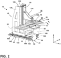
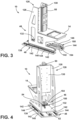
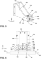
- FIGS. 2-13 various views of the additive manufacturing apparatus 10 are illustrated according to various aspects of the present disclosure. While only some components of the additive manufacturing apparatus are illustrated in FIGS. 2-13 for clarity purposes, it will be appreciated that the additive manufacturing apparatus may include any feature described in the present disclosure.
- the additive manufacturing apparatus may include a frame 126 and an actuator assembly 46 configured to allow for movement of various components of the additive manufacturing apparatus relative to one another.
- the frame 126 may include a frame structure 128 and may be operably coupled with and/or operably support various components of the additive manufacturing apparatus.
- the frame 126 may support a build plate 130, a support plate 14, and/or a base plate 132.
- the build plate 130 may support a first actuator 50.
- the first actuator 50 can allow for movement of the stage 18 in a first, vertical direction (e.g., along the Z-axis direction).
- the first actuator 50 may include any device practicable for moving the stage 18 in the Z-axis direction, such as ballscrew electric actuators, linear electric actuators, pneumatic cylinders, hydraulic cylinders, delta drives, belt systems, or any other practicable device.
- a print head 134 may be operably coupled with the first actuator 50. In such instances, the print head 134 may be configured to translate or otherwise through the actuation of the first actuator 50. The print head 134 may further be operably coupled with the stage 18. In some instances, the print head 134 may include a clamp 136 and/or any other feature for retaining the stage 18 on the print head 134.
- the frame 126 may further be operably coupled with the support plate 14.
- a window 16 can be operably supported by the support plate 14. Further, the window 16 and the support plate 14 can be integrally formed such that one or more windows 16 are integrated within the support plate 14.
- the base plate 132 may be fixed to a bottom portion of the frame structure 128.
- a first slide assembly 138 may be operably coupled with the base plate 132.
- the first slide assembly 138 may be configured to guide the movement of the base plate 132 relative to a mounting plate 140, which may be retained within a generally static position within the additive manufacturing apparatus 10. It will be appreciated, however, that the mounting plate 140 may be moveable.
- one or more guides 142 may be operably coupled with the base plate 132.
- the guides 142 may move along a track 144 operably coupled with the mounting plate 140.
- the first slide assembly 138 may allow for the frame 126, and, consequently, the stage 18 to translate along the track 144 in the Y-axis direction such that the stage 18 may be lowered onto a resin R and/or a constituent material M (and/or a second resin).
- the track 144 may be operably coupled with the base plate 132 and the guides 142 may be operably coupled with the mounting plate 140 without departing from the scope of the present disclosure.
- the first slide assembly 138 may include any components that allow for movement of the base plate 132 relative to the mounting plate 140 without departing from the teachings provided herein.
- the resin R includes any radiant-energy curable material, which is capable of adhering to or binding together the filler (if used) in the cured state.
- the constituent material M may be in the form of a short fiber (e.g., chopped fibers), metallic powders, carbon-based powders, ceramic powders (e.g., silicon carbide (SiC), aluminum oxide (Al 2 O 3 ), silicon dioxide (SiO2)), polymeric powders, and/or any other practicable constituent material.
- the resin R may be separated from the constituent material M by a gap 124.
- the stage 18 may be moved between the resin R and the constituent material M to form a composite component 12, which may be a short fiber reinforced composite having a 10 volume percent (or greater) fiber loading. Additionally or alternatively, the composite component 12 can have resin R and constituent material M of varied densities throughout the component 12. Additionally or alternatively, the composite component 12 can be formed from multiple materials, which may be of varied or common particle sizes.
- a second actuator 52 may be operably coupled with the base plate 132 and the mounting plate 140.
- the second actuator 52 may be configured to move the base plate 132 relative to the mounting plate 140 in the Y-axis direction.
- the second actuator 52 may include any practicable device, such as ballscrew electric actuators, linear electric actuators, pneumatic cylinders, hydraulic cylinders, delta drives, belt systems, or any other practicable device.
- the radiant energy device 20 may be operably coupled with the frame 126 and positioned on an opposing side of the window from the stage 18 in the Z-direction.
- the radiant energy device 20 may include a pair of projectors 56.
- the radiant energy device 20 may be configured as any device or combination of devices operable to generate and project radiant energy at the resin R in a suitable pattern and with a suitable energy level and other operating characteristics to cure the resin R during a build process.
- the radiant energy device 20 may be operably coupled with a carrier plate 146.
- the radiant energy device 20 may include one or more carrier rails 148 that are coupled with the carrier plate 146 for retaining the radiant energy device 20 relative to the carrier plate 146.
- the radiant energy device 20 may be movably coupled with the frame 126.
- a second slide assembly 150 may be positioned between the carrier plate 146 and the base plate 132.
- the second slide assembly 150 may be configured to guide the movement of the carrier plate 146 relative to the base plate 132.
- the stage 18 and the radiant energy device 20 may move in conjunction relative to the mounting panel with one another through the use of the first slide assembly 138 and the radiant energy device 20 may move relative to the stage 18 through use of the second slide assembly 150.
- one or more guides 152 may be operably coupled with the carrier plate 146.
- the guides 152 may move along a rail 154 operably coupled with the base plate 132.
- the second slide assembly 150 may allow for the radiant energy device 20 to translate along the second slide assembly 150 in the Y-axis direction such that the radiant energy device 20 may be aligned with various portions of the support 26.
- the rail 154 may be operably coupled with the carrier plate 146 and the guides 152 may be operably coupled with the base plate 132 without departing from the scope of the present disclosure.
- the second slide assembly 150 may be operably coupled with any other component, such as the frame 126 or the mounting plate 140 without departing from the teachings provided herein.
- a third actuator 54 may be operably coupled with the carrier plate 146 and the base plate 132.
- the third actuator 54 may be configured to move the carrier plate 146 relative to the base plate 132 in the Y-axis direction.
- the third actuator 54 may include any practicable device, such as ballscrew electric actuators, linear electric actuators, pneumatic cylinders, hydraulic cylinders, delta drives, belt systems, or any other practicable device.
- a cover 156 may be operably coupled with the frame 126 and configured to shield an area between the lenses of the radiant energy device 20 and the support plate 14.
- the shield may be configured to prevent light within various spectrums and/or all light from passing therethrough.
- the print head 134 may include a print head mounting plate 158, one or more print head arms 160 extending from the print head mounting plate 158, and an attachment assembly 162.
- the print head 134 may be configured to selectively retain the stage 18.
- the stage 18 is a structure defining a planar surface 44, which is capable of being oriented parallel to a build surface 30 or the X-Y plane.
- the stage 18 may further include one or more stage rails 164 that are configured to interact with the print head 134.
- One or more datums 166 may also be positioned on and/or integrally formed with the stage 18.
- the stage 18 may further include one or more handles 168.
- the clamp 136 of the attachment assembly 162 may selectively retain the stage 18 relative to the print head 134.
- the attachment assembly 162 may further include an anchor plate 170 and a clamping plate 172.
- the anchor plate 170 may maintain a common position when the clamp 136 is in both the unlocked and locked positions.
- the clamping plate 172 may be operably coupled with a clamping arm 174. The clamping plate 172 and the clamping arm 174 may move in conjunction with one another when the clamp 136 is moved from the unlocked position to the locked position and vice versa.
- the clamping arm 174 may include one or more protrusions 176 that are configured to be positioned within the one or more rails 154 of the stage 18.
- the one or more protrusions 176 may define notches 178 for assisting in locating the stage 18 relative to the protrusions 176.
- the one or more datums 166 of the stage 18 can align with locators 180 within the attachment assembly 162.
- a distance between a bottom portion of the locators 180 and a top portion of the clamping arm 174 is increased in the Z-axis direction. The increased distance creates an expansion force on the rails 154 of the stage 18 and the one or more datums 166 thereby retaining the stage 18 in position relative to the print head 134.
- the mounting plate 140 may have a pair of tracks 144 operably coupled thereto.
- a plurality of guides 142 are coupled with the base plate 132 and may be configured to move along the first slide assembly 138.
- the second actuator 52 may be operably coupled with the base plate 132 and the mounting plate 140 to move the base plate 132 relative to the mounting plate 140. In some instances, the second actuator 52 may be configured to move the base plate 132 between a first position and a second position.
- the stage 18 In the first position, the stage 18 may be lowered by the first actuator 50 ( FIG. 2 ) to a position over at least a portion of the resin R. When in the first position, the guides 142 may contact a first pair of stops 182. In the second position, the stage 18 may be lowered by the first actuator 50 ( FIG. 2 ) to a position over at least a portion of the constituent material M. When in the second position, the guides 142 may contact a second pair of stops 184. It will be appreciated that the first slide assembly 138 may include a single first stop and/or a single second stop without departing from the scope of the present disclosure.
- each of the first pair of stops 182 and the second pair of stops 184 may be adjustable.
- the first pair of stops 182, and the second pair of stops 184 can be in the form of fine threaded (e.g., 100 threads per inch (TPI)) adjustable end stops that allow precise positioning of each respective pair of end stops 182, 184.
- the one or more guides 142 may include hardened standoffs 186 that are configured to engage with end stops 182, 184. The standoffs 186 can be removable and replaceable thereby allowing for easy replacement once the standoffs 186 in use are worn from use and/or for any other reason.
- a second slide assembly 150 may include a pair of rails 154 operably coupled to the base plate 132.
- the second slide assembly 150 may also include one or more guides 152 coupled with the carrier plate 146.
- the guides 152 may be configured to move along the pair of rails 154.
- the third actuator 54 may be operably coupled with the base plate 132 and the carrier plate 146 to move the carrier plate 146 relative to the base plate 132. In some instances, the third actuator 54 may be configured to move the carrier plate 146 between a first position and a second position.
- the radiant energy device 20 may be positioned in a first location relative to the window 16 and/or the base plate 132.
- the guides 152 may contact a first stop 188.
- the radiant energy device 20 may be positioned in a second location relative to the window 16 and/or the base plate 132 that is offset from the first location in the Y-axis direction.
- the guides 152 may contact a second stop 190.
- the first stop 188 may be operably coupled to the base plate 132.
- the second stop 190 may be operably coupled with a flange 192 of the base plate 132.
- each of the first end stop and the second end stop may be adjustable.
- the first end stop, and the second end stop can be in the form of a fine threaded (e.g., 100 TPI) adjustable end stops that allow for precise positioning of each of the first end stop and the second end stop.
- a first standoff 186 may be supported by the carrier plate 146 and configured to align with the first end stop.
- a second standoff 186 may be operably coupled with an opposing end of the carrier plate 146 and/or the guides 152 of the second slide assembly 150.
- Each of the first standoff 186 and the second standoff 186 can be removable and replaceable thereby allowing for easy replacement once the standoffs 186 in use are worn from use and/or for any other reason.
- the additive manufacturing apparatus may be configured to deposit a resin Rand a constituent material M onto a support 26.
- the resin R may be laterally offset from the constituent material M on the support 26 in the Y-direction.
- a gap 124 may be defined between the laterally offset resin R and constituent material M.
- the actuator assembly 46 may include a first actuator 50 configured to move the stage 18 in a plurality of locations along the Z-axis direction.
- the actuator assembly 46 may also include a second actuator 52 that may be associated with the first slide assembly 138.
- the first slide assembly 138 may be configured to move the stage 18 relative to the mounting plate 140.
- the actuator assembly 46 may include a third actuator 54 that is may be associated with the second slide assembly 150.
- the second slide assembly 150 may be configured to move the radiant energy device 20 relative to the frame 126 and/or the window 16.
- the support 26 may be maintained in a generally consistent position.
- the stage 18 and/or the radiant energy device 20 may be movable relative to the support 26 such that the resin R (or various portions of the resin R) and/or the constituent material M (or various portions of the second resin R) may be selectively cured.
- the first slide assembly 138 may be placed in a first position relative to the mounting plate 140.
- the guides 142 of the first slide assembly 138 may contact and/or be proximate to the first pair of stops 182.
- the stage 18 In the first position, the stage 18 may be generally aligned with the resin R in the Y-axis direction.
- the second slide assembly 150 may be in the first position.
- the guides 152 of the second slide assembly 150 may contact and/or be proximate to the first stop 188 of the second slide assembly 150.
- the radiant energy device 20 may be in a first location relative to the window 16. As such, the radiant energy device 20 may be directed towards a first portion of the resin R.
- the second slide assembly 150 may alternatively be in the second position.
- the guides 152 of the second slide assembly 150 may contact and/or be proximate to the second stop 190 of the second slide assembly 150.
- the radiant energy device 20 may be in a second location relative to the window 16. As such, the radiant energy device 20 may be directed towards a second portion of the resin R.
- the first slide assembly 138 may also be placed in a second position relative to the mounting plate 140.
- the guides 142 of the first slide assembly 138 may contact and/or be proximate to the second pair of stops 184.
- the stage 18 In the second position, the stage 18 may be generally aligned with the constituent material Min the Y-axis direction.
- each of the slide assemblies may be manipulated in any order to form a component 12 formed from one or both of the resin R and the constituent material M.
- the radiant energy device 20 may be configured as any device or combination of devices operable to generate and project radiant energy at the resin R in a suitable pattern and with a suitable energy level and other operating characteristics to cure the resin R during the build process.
- the radiant energy device 20 may or may not be configured to translate below the window 16 and/or the support plate 14.
- the radiant energy device 20 may include a first projector 56 and a second projector 56.
- Each of the first projector 56 and the second projector 56 may generate an image 64 that at least partially overlaps with an image 64 of an additional radiant energy device to form a stitched image 64 on the resin R.
- the images 64 from each of the plurality of radiant energy devices 20 may have some degree of overlap where that overlap is a single pixel, less than one pixel (for example, half a pixel), or more than one pixel.
- the radiant energy device 20 may be capable of performing a scanning process in which the consecutive patterned images 64 are emitted from the radiant energy device 20 as the radiant energy device 20 is translated along the movement device 80.
- the image 64 from the first projector 56 and the image 64 from the second projector 56 may be statically, or mechanically, stitched together. Additionally or alternatively, multiple images 64 from the first projector 56 may be stitched with one another as the third actuator 54 alters a position of the first projector 56. Likewise, multiple images 64 from the second projector 56 may be stitched with one another as the third actuator 54 alters a position of the second projector 56.
- the apparatus 10 may include one or more sensors 194 that are configured to detect information related to a position of the printhead 134, the frame 126, and/or the radiant energy device 20.
- the one or more sensors 194 may verify the position of the stage 18 each time the stage 18 is moved. Additionally or alternatively, the one or more sensors 194 may verify the location of the frame 126 each time the frame 126 is translated. Additionally or alternatively, the one or more sensors 194 may verify the location of the radiant energy device 20 each time the radiant energy device 20 is translated by the movement device 80.
- the one or more sensors 194 may be any combination of devices that is configured to provide information indicative of a position of the printhead 134, the frame 126, and/or the radiant energy device 20.
- the one or more sensors 194 may include a gyroscope, an accelerometer, a proximity sensor, an image sensor, and/or any other practicable sensor.
- the additive manufacturing apparatus may be configured to deposit a resin R and a constituent material M onto a support 26.
- the resin R may be laterally offset from the constituent material M on the support 26 in the Y-direction.
- the frame 126 may be movable relative to the support plate 14 and the window 16. As such, in some instances, there may be little to no relative motion between the support 26 and the support plate 14 and the window 16 in the Y-axis direction.
- an opening 196 may be defined between the support plate 14 and the frame 126 to accommodate for movement of the frame 126 relative to the support plate 14.
- the opening 196 may have a length in the Y-axis direction that is at least equal to the length of travel of the build plate 130 when the frame 126 is moved from the first position to the second position.
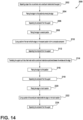
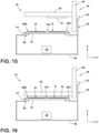
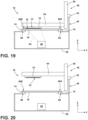
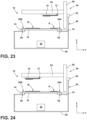
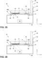
- FIG. 14 a method 200 for operating an additive manufacturing apparatus 10 is provided in accordance with various aspects of the present disclosure.
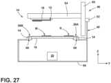
- the various steps of method 200 are schematically illustrated in FIGS. 14-27 .
- the method 200 can be used to operate the additive manufacturing apparatus 10 or any other suitable additive manufacturing apparatus 10. It should be appreciated that the example method 200 is discussed herein only to describe example aspects of the present subject matter and is not intended to be limiting. Any of the steps within FIG. 14 may be omitted without departing from the scope of the present disclosure.
- the method 200 can include, at step 202, depositing a layer of an uncured resin and a constituent material onto the support 26.
- the resin R may be laterally offset from the constituent material M on the support 26 in the Y-direction. Further, a gap 124 may be defined between the laterally offset resin Rand constituent material M.
- the support 26 may be in the form of a first support 26A that is configured to have the resin R deposited thereon and a second support 26B that is configured to have the constituent material M deposited thereon.
- Each of the first support 26A and the second support 26B may be operably coupled with the feed module 22 and the take-up module 24.
- the resin R and the constituent material M may be deposited on a common support 26.
- the support 26 may be translated in an X-axis direction into a build zone 32.
- the method 200 can include placing the stage 18 in a first position by moving the stage 18 such that a working surface of the stage 18 and/or the component 12 retained by the stage 18 contacts the resin R. As the stage 18 is moved to the first position, a working surface of the stage 18 and/or the component 12 retained by the stage 18 contacts the resin R.
- the method 200 can include partially curing a portion of the resin R while the stage 18 is in the first curing position relative to a window 16 by applying radiant energy from a radiant energy device 20 through the window 16 and the support 26. As provided herein, the radiant energy may be in the form of a first patterned image 64 that is transmitted through at least a portion of the window 16. The portion of the resin R that is cured forms a layer of the component 12 that is retained by the stage 18.
- the method 200 can include separating the component 12 from the support 26 by altering a position of the stage 18 through the actuator assembly 46. It will be appreciated that the stage 18 may move in the X-axis direction, the Y-axis direction, and/or the Z-axis direction.
- the method 200 can include placing the stage 18 in a second position by moving the stage 18 such that the working surface of the component 12 retained by the stage 18 contacts the constituent material M. As the stage 18 is moved to the second position, the working surface of the component 12 retained by the stage 18 contacts the constituent material M. As the resin R is at least partially uncured, the constituent material M may be at least partially within the resin R thereby forming a composite substance.
- the method 200 can include curing a portion of the resin R while the stage 18 is in the second position relative to a window 16 by applying radiant energy from a radiant energy device 20 through the window 16 and the support 26.
- the radiant energy may be in the form of a patterned image 64 that is transmitted through at least a portion of the window 16.
- the portion of the constituent material M that is cured forms a composite layer of the component 12 that is retained by the stage 18.
- the patterned image 64 is generally equal to the width of the constituent material M in the Y-axis direction.
- the second portion may be of any width (varied or constant) in the Y-axis direction.
- curing a portion of the resin R can further include positioning the radiant energy device 20 in a first projection position, wherein the portion of the resin is cured while the radiant energy device is in the first projection position. Additionally, curing a portion of the resin R can further include positioning the radiant energy device 20 in a second projection position, wherein the second projection curing position is offset from the first projection position in the Y-axis direction, and wherein the portion of the resin is cured while the radiant energy device 20 is in the second projection position.
- the method 200 can include separating the component 12 from the support 26 by altering a position of the stage 18 through the actuator assembly 46. It will be appreciated that the stage 18 may move in the X-axis direction, the Y-axis direction, and/or the Z-axis direction.
- the method 200 can include translating the support 26 such that a fresh resin R and/or a constituent material M are positioned between the window 16 and the stage 18. It will be appreciated, however, that in various embodiments, after a portion of the resin R is cured and/or the constituent material M is positioned within the resin R, the support 26 respectively supporting the resin R and/or the constituent material M may be translated. Additionally or alternatively, the support 26 may be translated whenever the next layer to be formed requires fresh resin R and/or constituent material M. While the support 26 is translated, the stage 18 and the component 12 attached to the stage 18 may move based on the next layer to be formed.
- the method 200 can include placing the stage 18 in a third position by moving the stage 18 such that the working surface of the component 12 retained by the stage 18 contacts the resin R. As the stage 18 is moved to the third position, the working surface of the component 12 retained by the stage 18 contacts the resin R. In some instances, the previous layer of constituent material M may extend externally of the working surface of the component 12 which may be positioned within the resin R when the stage 18 is positioned in the third position. In some instances, the method 200 can include partially curing a portion of the resin R while the stage 18 is in the third position relative to a window 16 by applying radiant energy from a radiant energy device 20 through the window 16 and the support 26.
- the radiant energy may be in the form of a patterned image 64 that is transmitted through at least a portion of the window 16.
- the portion of the resin R that is cured forms a layer of the component 12 that is retained by the stage 18.
- the patterned image 64 is less than the width of the resin R in the Y-axis direction.
- the cured portion may be of any width (varied or constant) in the Y-axis direction.
- the method 200 can include separating the component 12 from the support 26 by altering a position of the stage 18 through the actuator assembly 46. It will be appreciated that the stage 18 may move in the X-axis direction, the Y-axis direction, and/or the Z-axis direction.
- the method 200 can include placing the stage 18 in a fourth position by moving the stage 18 such that the working surface of the component 12 retained by the stage 18 contacts the constituent material M. As the stage 18 is moved to the fourth position, the working surface of the component 12 retained by the stage 18 contacts the constituent material M.
- the method 200 can include curing a portion of the constituent material M while the stage 18 is in the fourth position relative to a window 16 by applying radiant energy from a radiant energy device 20 through the window 16 and the support 26.
- the radiant energy may be in the form of a patterned image 64 that is transmitted through at least a portion of the window 16.
- the portion of the constituent material M that is cured forms a layer of the composite component 12 that is retained by the stage 18.
- the patterned image 64 is less than the width of the constituent material M in the Y-axis direction.
- the cured portion may be of any width (varied or constant) in the Y-axis direction.
- the method 200 can include separating the component 12 from the support 26 by altering a position of the stage 18 through the actuator assembly 46.
- the stage 18 may move in the X-axis direction, the Y-axis direction, and/or the Z-axis direction.
- the stage 18 and the support 26 may move to any number (one or more) positions to form each layer of the component 12 based on the component design.
- composite components having first and second layers which may be formed by the method described in FIGS. 14-27 , are illustrated according to various aspects of the present disclosure. While the illustrated component has a pair of layers, it will be appreciated that the component 12 may have any number (e.g., one or more) layers without departing from the teachings provided herein.
- the constituent material M may be in the form of a short fiber, which may have a length that is between 0.5 millimeters (mm) and 10 mm, or any other practicable length. Adding short fibers to the resin may improve the composite component performance for various applications.
- the fiber length distribution (FLD) may be of any practicable concentration and the fiber orientation distribution (FOD) may be of any practicable orientation.
- the FLD and/or the FOD may be common throughout the component 12 and/or varied within various portions of the component 12.
- the constituent material M may extend beyond a surface of the resin R for a respective layer.
- the resin R may surround at least some of the constituent material M extending beyond the resin R thereby further attaching subsequent layers of resin R to one another to further add rigidity to the composite component 12.
- one or more post-manufacturing processes may be used to remove any constituent material M that extends beyond a resin surface of the component 12.
- the constituent material M may be in the form of a powder, which may be a metallic powder, carbon-based powder, ceramic powder (e.g., Silicon carbide (SiC), aluminum oxide (Al2O3), silicon dioxide (SiO2)), polymeric powders, and/or any other practicable constituent material.
- the constituent material M may have a particle size between 1-1000 ⁇ m to form printed hybrid components 12 with a higher green density.
- the concentration and/or particle size of the constituent material M may be varied within various portions of the component 12.
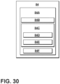
- FIG. 30 depicts certain components of a computing system 84 according to example embodiments of the present disclosure.
- the computing system 84 can include one or more computing device(s) 84A which may be used to implement the methods 200 described herein.
- the computing device(s) 84A can include one or more processor(s) 84B and one or more memory device(s) 84C.
- the one or more processor(s) 84B can include any suitable processing device, such as a microprocessor, microcontroller, integrated circuit, an application-specific integrated circuit (ASIC), a digital signal processor (DSP), a field-programmable gate array (FPGA), logic device, one or more central processing units (CPUs), graphics processing units (GPUs) (e.g., dedicated to efficiently rendering images), processing units performing other specialized calculations, etc.
- the memory device(s) 84C can include one or more non-transitory computer-readable storage medium(s), such as RAM, ROM, EEPROM, EPROM, flash memory devices, magnetic disks, etc., and/or combinations thereof.
- the memory device(s) 84C can include one or more computer-readable media and can store information accessible by the one or more processor(s) 84B, including instructions 84D that can be executed by the one or more processor(s) 84B.
- the instructions 84D may include one or more steps of the methods 200 described above, such as to execute operations at the additive manufacturing apparatus 10 described herein.
- the memory device(s) 84C can store instructions 84D for running one or more software applications, displaying a user interface, receiving user input, processing user input, etc.
- the instructions 84D can be executed by the one or more processor(s) 84B to cause the one or more processor(s) 84B to perform operations, e.g., such as one or more portions of the methods 200 described herein.
- the instructions 84D can be software written in any suitable programming language or can be implemented in hardware. Additionally, and/or alternatively, the instructions 84D can be executed in logically and/or virtually separate threads on the processor(s) 84B.
- the one or more memory device(s) 84C can also store data 84E that can be retrieved, manipulated, created, or stored by the one or more processor(s) 84B.
- the data 84E can include, for instance, data to facilitate the performance of the methods 200 described herein.
- the data 84E can be stored in one or more database(s).
- the one or more database(s) can be connected to computing system 84 by a high bandwidth LAN or WAN, or can also be connected to the computing system 84 through the network(s).
- the one or more database(s) can be split up so that they are located in multiple locales.
- the data 84E can be received from another device.
- the computing device(s) 84A can also include a communication module or interface 84F used to communicate with one or more another component (s) of the computing system 84 or the additive manufacturing apparatus 10 over the network(s).
- the communication interface 84F can include any suitable components for interfacing with one or more network(s), including, for example, transmitters, receivers, ports, controllers, antennas, or other suitable components.
- the additive manufacturing apparatus is described herein only for the purpose of explaining aspects of the present subject matter.
- the additive manufacturing apparatus may have any other suitable configuration and may use any other suitable additive manufacturing technology.
- the additive manufacturing apparatus and processes or methods 200 described herein may be used for forming components using any suitable material.
- the resin R may be plastic, metal, concrete, ceramic, polymer, epoxy, photopolymer powder, or any other suitable material that may be embodied in a layer of slurry, resin, or any other suitable form of sheet material having any suitable consistency, viscosity, or material properties.
- the additively manufactured components described herein may be formed in part, in whole, or in some combination of materials including but not limited to pure metals, nickel alloys, chrome alloys, titanium, titanium alloys, magnesium, magnesium alloys, aluminum, aluminum alloys, iron, iron alloys, stainless steel, and nickel or cobalt based superalloys (e.g., those available under the name Inconel ® available from Special Metals Corporation). These materials are examples of materials suitable for use in the additive manufacturing processes described herein and may be generally referred to as "additive materials.”
- An additive manufacturing apparatus comprising: a support configured to support a resin and a constituent material; a support plate including a window; a stage configured to hold one or more composite layers of the resin and the constituent material to form a composite component positioned opposite the support plate; a radiant energy device positioned on an opposite side of the support from the stage and operable to generate and project radiant energy in a patterned image through the window; and an actuator assembly configured to move the stage in a Z-axis direction and a Y-axis direction.
- the additive manufacturing apparatus of one or more of these clauses further comprising: a depositor configured to deposit the resin and the constituent material on the support.
- the additive manufacturing apparatus of one or more of these clauses further comprising: a frame operably coupled with the stage, the radiant energy device, and the support plate, the frame further coupled with a mounting plate; and a first slide assembly, wherein the frame, the stage, the radiant energy device, and the support plate are moveable relative to the mounting plate along the first slide assembly.
- an actuator of the actuator assembly is operably coupled with the frame and the mounting plate, and wherein the actuator is configured to move the frame between a first position and a second position along the first slide assembly.
- the additive manufacturing apparatus of one or more of these clauses further comprising: a second slide assembly operably coupled with the radiant energy device and the frame, wherein the radiant energy device is movable relative to the frame along the second slide assembly.
- the additive manufacturing apparatus of one or more of these clauses further comprising: a third actuator operably coupled with the frame and the radiant energy device, wherein the third actuator is configured to move the radiant energy device between a first position and a second position along the second slide assembly.
- a method of operating an additive manufacturing apparatus comprising: depositing a layer of a resin and a constituent material onto a support; placing a stage in a first position such that a working surface contacts the resin; placing the stage in a second position to intersperse the constituent material with the resin; and curing a portion of the resin while the stage is in the second position.
- An additive manufacturing apparatus comprising: a support configured to support a resin and a constituent material; a support plate including a window; a stage configured to hold first and second composite layers of the resin and the constituent material to form a composite component positioned opposite the support plate, the constituent material extending between the first and second composite layers; a radiant energy device positioned on an opposite side of the support from the stage and operable to generate and project radiant energy in a patterned image through the window; and an actuator assembly configured to move the stage in a Z-axis direction and a Y-axis direction.
- the additive manufacturing apparatus of one or more of these clauses further comprising: a first slide assembly operably coupled with the base plate of the frame and a mounting plate, the first slide assembly configured to guide movement of the frame relative to the mounting plate in a Y-axis direction.
- the additive manufacturing apparatus of one or more of these clauses further comprising: a second slide assembly positioned between the radiant energy device and the frame structure, the second slide assembly configured to guide movement of the radiant energy device relative to the window.
- the second slide assembly includes a rail operably coupled with the frame structure and one or more guides, the one or more guides slidable along the rail.
Landscapes
- Chemical & Material Sciences (AREA)
- Engineering & Computer Science (AREA)
- Materials Engineering (AREA)
- Manufacturing & Machinery (AREA)
- Physics & Mathematics (AREA)
- Mechanical Engineering (AREA)
- Optics & Photonics (AREA)
- Health & Medical Sciences (AREA)
- Toxicology (AREA)
Abstract
Description
- The present application claims priority to
United States Provisional Patent Application Serial No. 63/411,881, filed on September 30, 2022 - The present subject matter relates generally to an additive manufacturing apparatus, and more particularly to an additive manufacturing apparatus that can form multi-material components.
- Additive manufacturing is a process in which material is built up layer-by-layer to form a component. Stereolithography (SLA) is a type of additive manufacturing process, which employs a tank of radiant-energy curable photopolymer "resin" and a curing energy source such as a laser. Similarly, Digital Light Processing (DLP) three-dimensional (3D) printing employs a two-dimensional image projector to build components one layer at a time. For each layer, the energy source draws or flashes a radiation image of the cross section of the component onto the surface of the resin. Exposure to the radiation cures and solidifies the pattern in the resin and joins it to a previously cured layer.
- In some instances, additive manufacturing may be accomplished through a "tape casting" process. In this process, a resin is deposited onto a flexible radiotransparent support, such as a tape or foil, that is fed out from a supply reel to a build zone. Radiant energy is produced from a radiant energy device and directed through a window to cure the resin to a component that is supported by a stage in the build zone. Once the curing of the first layer is complete, the stage and the support are separated from one another. The support is then advanced and fresh resin is provided to the build zone. In turn, the first layer of the cured resin is placed onto the fresh resin and cured through the energy device to form an additional layer of the component. Subsequent layers are added to each previous layer until the component is completed. The tape casting process may be used to form various components.
- A full and enabling disclosure of the present disclosure, including the best mode thereof, directed to one of ordinary skill in the art, is set forth in the specification, which makes reference to the appended figures.
-
FIG. 1A is a schematic side view of an additive manufacturing apparatus in accordance with various aspects of the present disclosure; -
FIG. 1B is a schematic side view of an additive manufacturing apparatus in accordance with various aspects of the present disclosure; -
FIG. 2 is a side perspective view of the additive manufacturing apparatus in accordance with various aspects of the present disclosure; -
FIG. 3 is a side perspective view of a frame of the additive manufacturing apparatus in accordance with various aspects of the present disclosure; -
FIG. 4 is a rear perspective view of a frame of the additive manufacturing apparatus in accordance with various aspects of the present disclosure; -
FIG. 5 is a side perspective view of a print head of the additive manufacturing apparatus in accordance with various aspects of the present disclosure; -
FIG. 6 is a cross-sectional view of the print head of the additive manufacturing apparatus taken along the line VI-VI ofFIG. 2 in accordance with various aspects of the present disclosure; -
FIG. 7 is a top plan view of a first slide assembly of the additive manufacturing apparatus in accordance with various aspects of the present disclosure; -
FIG. 8 is a top plan view of a second slide assembly of the additive manufacturing apparatus in accordance with various aspects of the present disclosure; -
FIG. 9 is a side perspective view of the additive manufacturing apparatus with the stage in a first position and the radiant energy device in a first projection position in accordance with various aspects of the present disclosure; -
FIG. 10 is a side perspective view of the additive manufacturing apparatus with the stage in the first position and the radiant energy device in a second projection position in accordance with various aspects of the present disclosure; -
FIG. 11 is a side perspective view of the additive manufacturing apparatus with the stage in a second position and the radiant energy device in a third projection position in accordance with various aspects of the present disclosure; -
FIG. 12 is a side perspective view of the additive manufacturing apparatus with the stage in the second position and the radiant energy device in a fourth projection position in accordance with various aspects of the present disclosure; -
FIG. 13 is a side perspective view of the additive manufacturing apparatus in accordance with various aspects of the present disclosure; -
FIG. 14 is a method of operating the additive manufacturing apparatus in accordance with various aspects of the present disclosure; -
FIGS. 15-27 illustrate schematic views of the additive manufacturing apparatus during operation of the apparatus in accordance with various aspects of the present disclosure; -
FIG. 28 is a side perspective view of the component having short fibers in accordance with various aspects of the present disclosure; -
FIG. 29 is a side perspective view of the component having a powder in accordance with various aspects of the present disclosure; and -
FIG. 30 depicts an exemplary computing system for an additive manufacturing apparatus in accordance with various aspects of the present disclosure. - Repeat use of reference characters in the present specification and drawings is intended to represent the same or analogous features or elements of the present disclosure.
- Reference will now be made in detail to present embodiments of the invention, one or more examples of which are illustrated in the accompanying drawings. The detailed description uses numerical and letter designations to refer to features in the drawings. Like or similar designations in the drawings and description have been used to refer to like or similar parts of the invention.
- As used herein, the terms "first," "second," and "third" may be used interchangeably to distinguish one component from another and are not intended to signify a location or importance of the individual components. The terms "coupled," "fixed," "attached to," and the like refer to both direct coupling, fixing, or attaching, as well as indirect coupling, fixing, or attaching through one or more intermediate components or features, unless otherwise specified herein. The terms "upstream" and "downstream" refer to the relative direction with respect to a support movement along the manufacturing apparatus. For example, "upstream" refers to the direction from which the support moves, and "downstream" refers to the direction to which the support moves. The term "selectively" refers to a component's ability to operate in various states (e.g., an ON state and an OFF state) based on manual and/or automatic control of the component.
- The singular forms "a," "an," and "the" include plural references unless the context clearly dictates otherwise.
- Approximating language, as used herein throughout the specification and claims, is applied to modify any quantitative representation that could permissibly vary without resulting in a change in the basic function to which it is related. Accordingly, a value modified by a term or terms, such as "about," "approximately," "generally," and "substantially," is not to be limited to the precise value specified. In at least some instances, the approximating language may correspond to the precision of an instrument for measuring the value, or the precision of the methods or apparatus for constructing or manufacturing the components and/or systems. For example, the approximating language may refer to being within a ten percent margin.
- Moreover, the technology of the present application will be described in relation to exemplary embodiments. The word "exemplary" is used herein to mean "serving as an example, instance, or illustration." Any embodiment described herein as "exemplary" is not necessarily to be construed as preferred or advantageous over other embodiments. Additionally, unless specifically identified otherwise, all embodiments described herein should be considered exemplary.
- Here and throughout the specification and claims, range limitations are combined and interchanged, such ranges are identified and include all the sub-ranges contained therein unless context or language indicates otherwise. For example, all ranges disclosed herein are inclusive of the endpoints, and the endpoints are independently combinable with each other.
- As used herein, the term "and/or," when used in a list of two or more items, means that any one of the listed items can be employed by itself, or any combination of two or more of the listed items can be employed. For example, if a composition or assembly is described as containing components A, B, and/or C, the composition or assembly can contain A alone; B alone; C alone; A and B in combination; A and C in combination; B and C in combination; or A, B, and C in combination.
- The present disclosure is generally directed to an additive manufacturing apparatus that implements various manufacturing processes such that successive layers of material(s) are provided on each other to "build-up," layer-by-layer, a three-dimensional component. The successive layers generally cure together to form a monolithic component which may have a variety of integral sub-components. Although additive manufacturing technology is described herein as enabling the fabrication of complex objects by building objects point-by-point, layer-by-layer, variations of the described additive manufacturing apparatus and technology are possible and within the scope of the present subject matter.
- The additive manufacturing apparatus can include a support plate, a window supported by the support plate, and a stage moveable relative to the window. The additive manufacturing apparatus can further include a resin and a constituent material that are each deposited as layers having a desired thickness onto a support (such as a foil, tape, vat, plate, etc.). In various instances, the resin may be laterally offset from the constituent material in a Y-axis direction. In various examples, the constituent material M may be in the form of any material, that may be used to at elast partially form the component that is remote from the resin prior to formation of a layer of the component. In various examples, the constituent material M may be configured as a short fiber (e.g., chopped fibers), metallic powders, carbon-based powders, ceramic powders (e.g., silicon carbide (SiC), aluminum oxide (Al203), silicon dioxide (SiO2), other oxides, carbides, nitrides, borides, and/or anoy other material), polymeric powders, and/or any other practicable constituent material that may be interspersed with the resin to form a composite component.
- A stage can be configured to hold first and second composite layers of the resin and the constituent material to form a composite component positioned opposite the support plate. In some cases, the constituent material can extend between the first and second composite layers.
- In some cases, the additive manufacturing apparatus can produce short fiber (or other material) reinforced composites having greater than a ten percent by volume loading. Additionally or alternatively, the additive manufacturing apparatus can produce multi-material and multi-particle sizes parts, with common or varied densities throughout various portions of the component.
- Referring to the drawings wherein identical reference numerals denote the similar elements throughout the various views,
FIGS. 1A and1B schematically illustrate various examples ofapparatuses 10 for forming acomponent 12 created through one or more layers of at least one cured resin R and/or any other constituent material M. Theapparatus 10 can include one or more of asupport plate 14, awindow 16, astage 18 that is movable relative to thewindow 16, and aradiant energy device 20, which, in combination, may be used to form any number (e.g., one or more) of additively manufacturedcomponents 12. - In the illustrated example of
FIG. 1A , theapparatus 10 includes afeed module 22, which may include afirst roller 22A, and a take-upmodule 24, which may include asecond roller 24A, that are spaced-apart with asupport 26 extending therebetween. A portion of thesupport 26 can be supported from underneath by thesupport plate 14. Suitable mechanical supports (frames, brackets, etc.) and/or alignment devices may be provided for therollers support plate 14. Thefirst roller 22A and/or thesecond roller 24A can be configured to control the speed and direction of thesupport 26 such that the desired tension and speed are maintained in thesupport 26 through adrive system 28. By way of example and not limitation, thedrive system 28 can be configured as individual motors associated with thefirst roller 22A and/or thesecond roller 24A. Moreover, various components, such as motors, actuators, feedback sensors, and/or controls can be provided for driving therollers support 26 tensioned between the alignedrollers support 26 from thefirst roller 22A to thesecond roller 24A. - In various embodiments, the
window 16 is transparent and can be operably supported by thesupport plate 14. Further, thewindow 16 and thesupport plate 14 can be integrally formed such that one ormore windows 16 are integrated within thesupport plate 14. Likewise, thesupport 26 is also transparent or includes portions that are transparent. As used herein, the terms "transparent" and "radiotransparent" refer to a material that allows at least a portion of radiant energy of a selected wavelength to pass through. For example, the radiant energy that passes through thewindow 16 and thesupport 26 can be in the ultraviolet spectrum, the infrared spectrum, the visible spectrum, or any other practicable radiant energy. Non-limiting examples of transparent materials include polymers, glass, and crystalline minerals, such as sapphire or quartz. - The
support 26 extends between thefeed module 22 and the take-upmodule 24 and defines a "build surface" 30, which is shown as being planar, but could alternatively be arcuate (depending on the shape of the support plate 14). In some instances, the build surface 30 may be defined by thesupport 26 and be positioned to face thestage 18 with thewindow 16 on an opposing side of thesupport 26 from thestage 18. For purposes of convenient description, the build surface 30 may be considered to be oriented parallel to an X-Y plane of theapparatus 10, and a direction perpendicular to the X-Y plane is denoted as a Z-axis direction (X, Y, and Z being three mutually perpendicular directions). As used herein, the X-axis refers to the machine direction along the length of thesupport 26. As used herein, the Y-axis refers to the transverse direction across the width of thesupport 26 and generally perpendicular to the machine direction. As used herein, the Z-axis refers to the stage direction that can be defined as the direction of movement of thestage 18 relative to thewindow 16. - The build surface 30 may be configured to be "non-stick," that is, resistant to the adhesion of a cured resin R. The non-stick properties may be embodied by a combination of variables such as the chemistry of the
support 26, its surface finish, and/or applied coatings. For example, thesupport 26 may be formed from biaxially oriented polypropylene. Additionally or latenrtaively, a permanent or semi-permanent non-stick coating may be applied. One non-limiting example of a suitable coating is polytetrafluoroethylene ("PTFE"). In some examples, all or a portion of the build surface 30 may incorporate a controlled roughness or surface texture (e.g. protrusions, dimples, grooves, ridges, etc.) with nonstick properties. Additionally or alternatively, thesupport 26 may be made in whole or in part from an oxygen-permeable material. - For reference purposes, an area or volume immediately surrounding the location of the
support 26 and thewindow 16 or transparent portion defined by thesupport plate 14 may be defined as a "build zone," labeled 32. - In some instances, a
depositor 34 may be positioned along thesupport 26. Thedepositor 34 may be any device or combination of devices that is operable to dispose resin R and/or any other constituent material M on thesupport 26. Thedepositor 34 may optionally include a device or combination of devices to define a height of a resin R and/or any other constituent material M on thesupport 26 and/or to level the resin R and/or any other constituent material M on thesupport 26. Nonlimiting examples of suitable material deposition devices include chutes, rollers, hoppers, pumps, spray nozzles, spray bars, or printheads (e.g. inkjets). In some examples, a doctor blade may be used to control the thickness of and/or any other constituent material M applied to thesupport 26 as thesupport 26 passes thedepositor 34. - In the illustrated example of
FIG. 1B , thesupport 26 may be in the form of avat 36 that is configured to isolate debris that could contaminate the build from usable resin R. Thevat 36 may include afloor 38 and aperimeter wall 40. Theperimeter wall 40 extends from thefloor 38. Inner surfaces of thefloor 38 and theperimeter wall 40 define areceptacle 42 for receiving the resin R and/or any other constituent material M. As illustrated, theadditive manufacturing apparatus 10 can include afirst vat 36 that may retain a resin R therein and asecond vat 36 that may retain the constituent material M therein. - A drive system 28 (
FIG. 1A ) may be provided for moving thevat 36 relative to thestage 18 parallel to the X-direction between abuild zone 32 and a position at least partially external to thebuild zone 32. However, it will be appreciated that, in other embodiments, thesupport 26 may be stationary without departing from the scope of the present disclosure. - Referring back to
FIGS. 1A and1B , the resin R includes any radiant-energy curable material, which is capable of adhering to or binding together the filler (if used) in the cured state. As used herein, the term "radiant-energy curable" refers to any material which solidifies or partially solidifies in response to the application of radiant energy of a particular frequency and energy level. For example, the resin R may include a photopolymer resin containing photo-initiator compounds functioning to trigger a polymerization reaction, causing the resin R to change from a liquid (or powdered) state to a solid state. Alternatively, the resin R may include a material that contains a solvent that may be evaporated out by the application of radiant energy. The uncured resin R may be provided in solid (e.g. granular) or liquid form, including a paste or slurry. - Furthermore, the resin R can have a relatively high viscosity resin that will not "slump" or run off during the build process. The composition of the resin R may be selected as desired to suit a particular application. Mixtures of different compositions may be used. The resin R may be selected to have the ability to out-gas or burn off during further processing, such as a sintering process.
- Additionally or alternatively, the resin R may be selected to be a viscosity-reducible composition. These compositions reduce in viscosity when a shear stress is applied or when they are heated. For example, the resin R may be selected to be shear-thinning such that the resin R exhibits reduced viscosity as an amount of stress applied to the resin R increases. Additionally or alternatively, the resin R may be selected to reduce in the viscosity as the resin R is heated.
- The resin R may include a filler. The filler may be pre-mixed with resin R, then loaded into the
depositor 34. Alternatively, the filler may be mixed with the resin R on theapparatus 10. The filler may include any material that is chemically and physically compatible with the selected resin R. The particles may be regular or irregular in shape, may be uniform or non-uniform in size, and may have variable aspect ratios. For example, the particles may take the form of powder, small spheres, or granules, or may be shaped like small rods or fibers. - The composition of the filler, including its chemistry and microstructure, may be selected as desired to suit a particular application. For example, the filler may be metallic, ceramic, polymeric, and/or organic. Other examples of potential fillers include diamond, silicon, and graphite. Mixtures of different compositions may be used. In some examples, the filler composition may be selected for its electrical or electromagnetic properties, e.g. it may specifically be an electrical insulator, a dielectric material, an electrical conductor, and/or magnetic.
- The filler may be "fusible," meaning it is capable of consolidation into a mass upon application of sufficient energy. For example, fusibility is a characteristic of many available powders including but not limited to polymeric, ceramic, glass, and metallic. The proportion of filler to resin R may be selected to suit a particular application. Generally, any amount of filler may be used so long as the combined material is capable of flowing and being leveled, and there is sufficient resin R to hold together the particles of the filler in the cured state.
- Additionally, the constituent material M may be in the form of a solid material, such as a short fiber (e.g., chopped fibers), metallic powders, carbon-based powders, ceramic powders (e.g., silicon carbide (SiC), aluminum oxide (Al2O3), silicon dioxide (SiO2)), polymeric powders, and/or any other practicable constituent material. As used herein, the term "powder" is defined as a substance comprised of ground, pulverized, or otherwise dispersed solid particles. In some cases, the constituent material M may have a particle size in the longest direction from about 1 to about 1000 µm to form printed
hybrid components 12 with a higher green density. In certain other embodiments, the powder may have a particle size in the longest dimension from about 5 microns to about 40 microns. The particle shape of the powder may be spherical, ellipsoidal, or irregular. In any manner, the constituent material M may be any material that may be interspersed with the resin R to form acomposite component 12. - The
stage 18 is a structure defining aplanar surface 44, which is capable of being oriented parallel to the build surface 30 or the X-Y plane. Various devices may be provided for moving thestage 18 relative to thewindow 16. For example, as illustrated inFIGS. 1A and1B , the movement may be provided through anactuator assembly 46 that may be coupled with astatic support 48. In some embodiments, theactuator assembly 46 may include afirst actuator 50 between thestage 18 and thestatic support 48 that allows for movement of thestage 18 in a first, vertical direction (e.g., along the Z-axis direction). Theactuator assembly 46 may additionally or alternatively include asecond actuator 52 between thestage 18 and thefirst actuator 50 and/or thestatic support 48 that allows for movement in the X-axis direction and/or the Y-axis direction. Theactuator assembly 46 may additionally or alternatively include athird actuator 54 between thestage 18 and thesecond actuator 52 and/or thestage 18 that allows for movement in the X-axis direction and/or the Y-axis direction. Theactuator assembly 46 may include any device practicable for moving thestage 18 in any direction, such as ballscrew electric actuators, linear electric actuators, pneumatic cylinders, hydraulic cylinders, delta drives, belt systems, or any other practicable device. It will be appreciated that, in other examples, the support may additionally or alternatively translate in the Y-axis direction (or any other direction). - The
radiant energy device 20 may be configured as any device or combination of devices operable to generate and project radiant energy at the resin R in a suitable pattern and with a suitable energy level and other operating characteristics to cure the resin R during the build process. For example, as shown inFIGS. 1A and1B , theradiant energy device 20 may include aprojector 56, which may generally refer to any device operable to generate a radiant energy predetermined patterned image of suitable energy level and other operating characteristics to cure the resin R. As used herein, the term "patterned image" refers to a projection of radiant energy comprising an array of one or more individual pixels. Non-limiting examples of patterned image devices include a DLP projector or another digital micromirror device, a two-dimensional array of LEDs, a two-dimensional array of lasers, and/or optically addressed light valves. In the illustrated example, theprojector 56 includes aradiant energy source 58 such as a UV lamp, animage forming apparatus 60 operable to receive asource beam 62 from theradiant energy source 58 and generate apatterned image 64 to be projected onto the surface of the resin R, and optionally focusingoptics 66, such as one or more lenses. - The
image forming apparatus 60 may include one or more mirrors, prisms, and/or lenses and is provided with suitable actuators, and arranged so that thesource beam 62 from theradiant energy source 58 can be transformed into apixelated image 64 in an X-Y plane coincident with the surface of the resin R. In the illustrated example, theimage forming apparatus 60 may be a digital micro-mirror device. - The
projector 56 may incorporate additional components, such as actuators, mirrors, etc. configured to selectively move theimage forming apparatus 60 or other part of theprojector 56 with the effect of rastering or shifting the location of the patternedimage 64 on the build surface 30. Stated another way, the patternedimage 64 may be moved away from a nominal or starting location. - In addition to other types of
radiant energy devices 20, theradiant energy device 20 may include a "scanned beam apparatus" used herein to refer generally to any device operable to generate a radiant energy beam of suitable energy level and other operating characteristics to cure the resin R and to scan the beam over the surface of the resin R in a desired pattern. For example, the scanned beam apparatus can include aradiant energy source 58 and a beam steering apparatus. Theradiant energy source 58 may include any device operable to generate a beam of suitable power and other operating characteristics to cure the resin R. Non-limiting examples of suitableradiant energy sources 58 include lasers or electron beam guns. - In some instances, the
apparatus 10 may include aretention assembly 68 that may be configured to retain thesupport 26 in a predefined position along thesupport plate 14. In some instances, theretention assembly 68 can include one or morepneumatic actuation zones 70 with eachpneumatic actuation zone 70 configured to selectively interact with thesupport 26 by producing a force on a surface of thesupport 26 opposite the resin R. - The one or more
pneumatic actuation zones 70 may apply a negative pressure on a first surface of thesupport 26 that is opposite to the resin R, or a second side of thesupport 26, to produce a suction or vacuum on thesupport 26. The negative pressure may retain thesupport 26 in a desired position along thesupport plate 14. The one or morepneumatic actuation zones 70 may also apply a positive pressure on the first surface of thesupport 26 that is opposite to the resin R, or a second side of thesupport 26, to produce a pushing force on thesupport 26. The positive pressure may release thesupport 26 from a component of theapparatus 10, such as thewindow 16, theretention assembly 68, etc. As used herein, a "negative" pressure is any pressure that is less than an ambient pressure proximate to one or morepneumatic actuation zones 70 such that fluid may be drawn into the one or morepneumatic actuation zones 70. Conversely, a "positive" pressure is any pressure that is greater than an ambient pressure proximate to one or morepneumatic actuation zones 70 such that fluid may be exhausted from the one or morepneumatic actuation zones 70. Further, a "neutral" pressure is any pressure that is generally equal to an ambient pressure proximate to one or morepneumatic actuation zones 70. - In some examples, the
pneumatic actuation zones 70 may be fluidly coupled with apneumatic assembly 72 through various hoses and one or more ports. Thepneumatic assembly 72 may include any device capable of providing a vacuum/suction and/or pushing a fluid, such as air or a process gas (e.g., nitrogen or argon), through the one or morepneumatic actuation zones 70. For instance, thepneumatic assembly 72 may include a pressurized fluid source that includes a compressor and/or a blower. Thepneumatic assembly 72 may additionally or alternatively include any assembly capable of altering a pressure, such as a venturi vacuum pump. In some embodiments, one or more valves and/or switches may be coupled with thepneumatic assembly 72 and the one or morepneumatic actuation zones 70. The one or more valves and/or switches are configured to regulate a pressure to each of the one or morepneumatic actuation zones 70. - In some embodiments, the
pneumatic actuation zone 70 includes one ormore apertures 74 of any size and shape for interacting with thesupport 26. For instance, theapertures 74 may be any number and combination of holes, slits, or other geometric shapes defined by any component of theadditive manufacturing apparatus 10, such as a portion of thesupport plate 14. Additionally, or alternatively, theapertures 74 may be defined by a portion of thesupport plate 14 being formed from a porous material, or through any other assembly in which a fluid may be moved from a first side of thesupport plate 14 to a second side of thesupport plate 14 to interact with thesupport 26. - In some examples, the
pneumatic actuation zone 70 may be defined by aplenum 76. Theplenum 76 may be of any size and may be similar or varied from the shape of any remainingplenum 76. In some instances, a gasket may be positioned about a rim of theplenum 76. Additionally or alternatively, theretention assembly 68 may include one or more clamps that compressively maintain thesupport 26 along thesupport plate 14. - With further reference to
FIGS. 1A and1B , amovement assembly 78 may be integrated within thesupport plate 14 and/or otherwise operably coupled with thesupport 26. Themovement assembly 78 may be configured to apply a shearing stress to the resin R to alter (e.g., reduce) a viscosity of the resin R. Additionally or alternatively, themovement assembly 78 may be configured to heat the resin R to alter the viscosity of the resin R. It will be appreciated that in embodiments that heat the resin R to alter the viscosity of the resin R, the heat provided may be within a predefined range that is sufficient to alter the viscosity of the resin R without causing any cross-linking in the polymer. Additionally or alternatively, themovement assembly 78 may level, alter a packing density, and/or alter an orientation of any other constituent material M that may be positioned on thesupport 26. - In some embodiments, the
movement assembly 78 may be configured to mechanically vibrate a portion of thesupport plate 14 to create a shearing stress on the resin R. For example, themovement assembly 78 may include a movement device 80 (e.g., a transducer) that is operably coupled with thesupport plate 14. Themovement device 80 may be configured to vibrate at least a portion of thesupport plate 14 or any other module of theapparatus 10 that is then transferred to the resin R. Additionally and/or alternatively, themovement device 80 may be configured to convert electrical energy to ultrasonic mechanical pressure waves that are transferred to the resin R. For instance, themovement device 80 may be in the form of an ultrasonic vibrating device, such as one utilizing a piezoelectric transducer. In other embodiments, themovement assembly 78, in addition to or in lieu of the transducer, may include, alone or in conjunction with one or the other, a fluid, an acoustic, a motor (e.g., offset cam), a reciprocating piston, or anyother movement device 80. - The
movement device 80 may be operably coupled with acomputing system 84. Thecomputing system 84 may include a signal generator that supplies an electric impulse to themovement device 80, the voltage of which can be varied at different frequencies and with different waveshapes. The signal may, for example, be a pure sinusoidal wave or may be modulated with one or more other frequencies. Alternatively, the signal may be a stepped or spiked pulse. In some embodiments, the signal generator transmits a signal of between 20-80 kHz. For example, the signal is at about 60 kHz. The signal generator may, for example, transmit a constant amplitude signal at a constant frequency, or alternate one or both of these parameters. A power level can be selected as a percentage of maximum power. - In other embodiments, the
movement assembly 78 may be configured to create a shearing stress on the resin R through other configurations without departing from the scope of the present disclosure. For example, themovement assembly 78 may be configured as a probe that may be adjacent and in physical contact with thesupport 26 and/or any other module that may relay the shearing stress to the resin R on thesupport 26. Additionally or alternatively, themovement assembly 78 may be configured as an ultrasonic or vibration plate that may be operably coupled with thesupport 26 and/or any other module of theapparatus 10 that may provide the shearing stress to the resin R on thesupport 26. - With further reference to
FIGS. 1A and1B , in various embodiments, agasket 82 may be positioned between thewindow 16 and thesupport plate 14 to isolate movement of each of thewindow 16 and thesupport plate 14 from one another. By isolating movement of thewindow 16 from thesupport plate 14, degradation issues of theapparatus 10 caused through the operation ofmovement assembly 78 may be mitigated. In various examples, thegasket 82 may be formed from a motion attenuating material, such as any of a wide variety of resilient elastomers including, but not limited to, materials containing natural rubber and silicone. - As provided herein, in some instances, the
movement assembly 78 may additionally or alternatively be capable of producing heat to alter the viscosity of the resin R. For example, fast heating processes, such as dielectric or microwave heating, can be used to avoid exposing the resin R to a long heating cycle before the temperature of use is reached. - The
computing system 84 inFIGS. 1A and1B is a generalized representation of the hardware and software that may be implemented to control the operation of theapparatus 10, including some or all of thestage 18, thedrive system 28, theradiant energy device 20, theactuator assembly 46, theretention assembly 68, themovement assembly 78, amovement device 80, actuators, and the various parts of theapparatus 10 described herein. Thecomputing system 84 may be embodied, for example, by software running on one or more processors embodied in one or more devices such as a programmable logic controller ("PLC") or a microcomputer. Such processors may be coupled to process sensors and operating components, for example, through wired or wireless connections. The same processor or processors may be used to retrieve and analyze sensor data, for statistical analysis, and for feedback control. Numerous aspects of theapparatus 10 may be subject to closed-loop control. - Optionally, the components of the
apparatus 10 may be surrounded by ahousing 86, which may be used to provide a shielding or inert gas (e.g., a "process gas") atmosphere usinggas ports 88. Optionally, the pressure within thehousing 86 could be maintained at a desired level greater than or less than atmospheric. Optionally, thehousing 86 could be temperature and/or humidity controlled. Optionally, ventilation of thehousing 86 could be controlled based on factors such as a time interval, temperature, humidity, and/or chemical species concentration. In some embodiments, thehousing 86 can be maintained at a pressure that is different than an atmospheric pressure. - Referring now to
FIGS. 2-13 , various views of theadditive manufacturing apparatus 10 are illustrated according to various aspects of the present disclosure. While only some components of the additive manufacturing apparatus are illustrated inFIGS. 2-13 for clarity purposes, it will be appreciated that the additive manufacturing apparatus may include any feature described in the present disclosure. - In the embodiments illustrated in
FIGS. 2-13 , the additive manufacturing apparatus may include aframe 126 and anactuator assembly 46 configured to allow for movement of various components of the additive manufacturing apparatus relative to one another. In some instances, theframe 126 may include aframe structure 128 and may be operably coupled with and/or operably support various components of the additive manufacturing apparatus. As illustrated, theframe 126 may support abuild plate 130, asupport plate 14, and/or abase plate 132. - The
build plate 130 may support afirst actuator 50. In some embodiments, thefirst actuator 50 can allow for movement of thestage 18 in a first, vertical direction (e.g., along the Z-axis direction). Thefirst actuator 50 may include any device practicable for moving thestage 18 in the Z-axis direction, such as ballscrew electric actuators, linear electric actuators, pneumatic cylinders, hydraulic cylinders, delta drives, belt systems, or any other practicable device. - A
print head 134 may be operably coupled with thefirst actuator 50. In such instances, theprint head 134 may be configured to translate or otherwise through the actuation of thefirst actuator 50. Theprint head 134 may further be operably coupled with thestage 18. In some instances, theprint head 134 may include aclamp 136 and/or any other feature for retaining thestage 18 on theprint head 134. - The
frame 126 may further be operably coupled with thesupport plate 14. In various embodiments, awindow 16 can be operably supported by thesupport plate 14. Further, thewindow 16 and thesupport plate 14 can be integrally formed such that one ormore windows 16 are integrated within thesupport plate 14. - With further reference to
FIGS. 2-13 , thebase plate 132 may be fixed to a bottom portion of theframe structure 128. Afirst slide assembly 138 may be operably coupled with thebase plate 132. Thefirst slide assembly 138 may be configured to guide the movement of thebase plate 132 relative to a mountingplate 140, which may be retained within a generally static position within theadditive manufacturing apparatus 10. It will be appreciated, however, that the mountingplate 140 may be moveable. - In the embodiments illustrated in
FIGS. 2-13 , one ormore guides 142 may be operably coupled with thebase plate 132. Theguides 142 may move along atrack 144 operably coupled with the mountingplate 140. As will be described in greater detail below, thefirst slide assembly 138 may allow for theframe 126, and, consequently, thestage 18 to translate along thetrack 144 in the Y-axis direction such that thestage 18 may be lowered onto a resin R and/or a constituent material M (and/or a second resin). In some embodiments, thetrack 144 may be operably coupled with thebase plate 132 and theguides 142 may be operably coupled with the mountingplate 140 without departing from the scope of the present disclosure. In addition, thefirst slide assembly 138 may include any components that allow for movement of thebase plate 132 relative to the mountingplate 140 without departing from the teachings provided herein. - As provided herein, the resin R includes any radiant-energy curable material, which is capable of adhering to or binding together the filler (if used) in the cured state. Additionally, the constituent material M may be in the form of a short fiber (e.g., chopped fibers), metallic powders, carbon-based powders, ceramic powders (e.g., silicon carbide (SiC), aluminum oxide (Al2O3), silicon dioxide (SiO2)), polymeric powders, and/or any other practicable constituent material. As shown, the resin R may be separated from the constituent material M by a
gap 124. As such, thestage 18 may be moved between the resin R and the constituent material M to form acomposite component 12, which may be a short fiber reinforced composite having a 10 volume percent (or greater) fiber loading. Additionally or alternatively, thecomposite component 12 can have resin R and constituent material M of varied densities throughout thecomponent 12. Additionally or alternatively, thecomposite component 12 can be formed from multiple materials, which may be of varied or common particle sizes. - In various embodiments, a
second actuator 52 may be operably coupled with thebase plate 132 and the mountingplate 140. Thesecond actuator 52 may be configured to move thebase plate 132 relative to the mountingplate 140 in the Y-axis direction. Thesecond actuator 52 may include any practicable device, such as ballscrew electric actuators, linear electric actuators, pneumatic cylinders, hydraulic cylinders, delta drives, belt systems, or any other practicable device. - Referring still to
FIGS. 2-13 , in various embodiments, theradiant energy device 20 may be operably coupled with theframe 126 and positioned on an opposing side of the window from thestage 18 in the Z-direction. In the illustrated embodiments, theradiant energy device 20 may include a pair ofprojectors 56. However, it will be appreciated that theradiant energy device 20 may be configured as any device or combination of devices operable to generate and project radiant energy at the resin R in a suitable pattern and with a suitable energy level and other operating characteristics to cure the resin R during a build process. - In some embodiments, the
radiant energy device 20 may be operably coupled with acarrier plate 146. In some instances, theradiant energy device 20 may include one or more carrier rails 148 that are coupled with thecarrier plate 146 for retaining theradiant energy device 20 relative to thecarrier plate 146. - In several embodiments, the
radiant energy device 20 may be movably coupled with theframe 126. For example, asecond slide assembly 150 may be positioned between thecarrier plate 146 and thebase plate 132. Thesecond slide assembly 150 may be configured to guide the movement of thecarrier plate 146 relative to thebase plate 132. As such, in some examples, thestage 18 and theradiant energy device 20 may move in conjunction relative to the mounting panel with one another through the use of thefirst slide assembly 138 and theradiant energy device 20 may move relative to thestage 18 through use of thesecond slide assembly 150. - In the embodiments illustrated in
FIGS. 2-13 , one ormore guides 152 may be operably coupled with thecarrier plate 146. Theguides 152 may move along arail 154 operably coupled with thebase plate 132. In some cases, thesecond slide assembly 150 may allow for theradiant energy device 20 to translate along thesecond slide assembly 150 in the Y-axis direction such that theradiant energy device 20 may be aligned with various portions of thesupport 26. It will be appreciated that in other embodiments, therail 154 may be operably coupled with thecarrier plate 146 and theguides 152 may be operably coupled with thebase plate 132 without departing from the scope of the present disclosure. In addition, it will be appreciated that thesecond slide assembly 150 may be operably coupled with any other component, such as theframe 126 or the mountingplate 140 without departing from the teachings provided herein. - In various embodiments, a
third actuator 54 may be operably coupled with thecarrier plate 146 and thebase plate 132. Thethird actuator 54 may be configured to move thecarrier plate 146 relative to thebase plate 132 in the Y-axis direction. Thethird actuator 54 may include any practicable device, such as ballscrew electric actuators, linear electric actuators, pneumatic cylinders, hydraulic cylinders, delta drives, belt systems, or any other practicable device. - As illustrated in
FIG. 2 , acover 156 may be operably coupled with theframe 126 and configured to shield an area between the lenses of theradiant energy device 20 and thesupport plate 14. In various embodiments, the shield may be configured to prevent light within various spectrums and/or all light from passing therethrough. - Referring further to
FIGS. 5 and 6 , theprint head 134 may include a printhead mounting plate 158, one or moreprint head arms 160 extending from the printhead mounting plate 158, and anattachment assembly 162. Theprint head 134 may be configured to selectively retain thestage 18. - In some embodiments, such as the one illustrated in
FIG. 6 , thestage 18 is a structure defining aplanar surface 44, which is capable of being oriented parallel to a build surface 30 or the X-Y plane. Thestage 18 may further include one ormore stage rails 164 that are configured to interact with theprint head 134. One ormore datums 166 may also be positioned on and/or integrally formed with thestage 18. In some instances, thestage 18 may further include one or more handles 168. - Referring back to
FIGS. 5 and 6 , theclamp 136 of theattachment assembly 162 may selectively retain thestage 18 relative to theprint head 134. In addition, theattachment assembly 162 may further include ananchor plate 170 and aclamping plate 172. In operation, theanchor plate 170 may maintain a common position when theclamp 136 is in both the unlocked and locked positions. The clampingplate 172 may be operably coupled with aclamping arm 174. The clampingplate 172 and theclamping arm 174 may move in conjunction with one another when theclamp 136 is moved from the unlocked position to the locked position and vice versa. - The clamping
arm 174 may include one ormore protrusions 176 that are configured to be positioned within the one ormore rails 154 of thestage 18. In some instances, the one ormore protrusions 176 may definenotches 178 for assisting in locating thestage 18 relative to theprotrusions 176. With the one ormore protrusions 176 within the one ormore rails 154 of thestage 18, the one ormore datums 166 of thestage 18 can align withlocators 180 within theattachment assembly 162. In various embodiments, as theclamp 136 is moved to the locked position, a distance between a bottom portion of thelocators 180 and a top portion of theclamping arm 174 is increased in the Z-axis direction. The increased distance creates an expansion force on therails 154 of thestage 18 and the one ormore datums 166 thereby retaining thestage 18 in position relative to theprint head 134. - Referring further to
FIGS. 7 and 8 , as provided herein, the mountingplate 140 may have a pair oftracks 144 operably coupled thereto. A plurality ofguides 142 are coupled with thebase plate 132 and may be configured to move along thefirst slide assembly 138. As illustrated, thesecond actuator 52 may be operably coupled with thebase plate 132 and the mountingplate 140 to move thebase plate 132 relative to the mountingplate 140. In some instances, thesecond actuator 52 may be configured to move thebase plate 132 between a first position and a second position. - In the first position, the
stage 18 may be lowered by the first actuator 50 (FIG. 2 ) to a position over at least a portion of the resin R. When in the first position, theguides 142 may contact a first pair ofstops 182. In the second position, thestage 18 may be lowered by the first actuator 50 (FIG. 2 ) to a position over at least a portion of the constituent material M. When in the second position, theguides 142 may contact a second pair ofstops 184. It will be appreciated that thefirst slide assembly 138 may include a single first stop and/or a single second stop without departing from the scope of the present disclosure. - In various embodiments, each of the first pair of
stops 182 and the second pair ofstops 184 may be adjustable. For example, the first pair ofstops 182, and the second pair ofstops 184 can be in the form of fine threaded (e.g., 100 threads per inch (TPI)) adjustable end stops that allow precise positioning of each respective pair of end stops 182, 184. In some embodiments, the one ormore guides 142 may includehardened standoffs 186 that are configured to engage with end stops 182, 184. Thestandoffs 186 can be removable and replaceable thereby allowing for easy replacement once thestandoffs 186 in use are worn from use and/or for any other reason. - With further reference to
FIG. 8 , as provided herein, asecond slide assembly 150 may include a pair ofrails 154 operably coupled to thebase plate 132. Thesecond slide assembly 150 may also include one ormore guides 152 coupled with thecarrier plate 146. Theguides 152 may be configured to move along the pair ofrails 154. As illustrated, thethird actuator 54 may be operably coupled with thebase plate 132 and thecarrier plate 146 to move thecarrier plate 146 relative to thebase plate 132. In some instances, thethird actuator 54 may be configured to move thecarrier plate 146 between a first position and a second position. - In the first position, the
radiant energy device 20 may be positioned in a first location relative to thewindow 16 and/or thebase plate 132. When in the first position, theguides 152 may contact a first stop 188. In the second position, theradiant energy device 20 may be positioned in a second location relative to thewindow 16 and/or thebase plate 132 that is offset from the first location in the Y-axis direction. When in the second position, theguides 152 may contact a second stop 190. - In the illustrated embodiment of
FIG. 8 , the first stop 188 may be operably coupled to thebase plate 132. The second stop 190 may be operably coupled with aflange 192 of thebase plate 132. In various embodiments, each of the first end stop and the second end stop may be adjustable. For example, the first end stop, and the second end stop can be in the form of a fine threaded (e.g., 100 TPI) adjustable end stops that allow for precise positioning of each of the first end stop and the second end stop. In some embodiments, afirst standoff 186 may be supported by thecarrier plate 146 and configured to align with the first end stop. Asecond standoff 186 may be operably coupled with an opposing end of thecarrier plate 146 and/or theguides 152 of thesecond slide assembly 150. Each of thefirst standoff 186 and thesecond standoff 186 can be removable and replaceable thereby allowing for easy replacement once thestandoffs 186 in use are worn from use and/or for any other reason. - Referring now to
FIGS. 9-11 , various perspective views of the additive manufacturing apparatus having theactuator assembly 46 are provided in accordance with various aspects of the present disclosure. As provided herein, the additive manufacturing apparatus may be configured to deposit a resin Rand a constituent material M onto asupport 26. The resin R may be laterally offset from the constituent material M on thesupport 26 in the Y-direction. In addition, agap 124 may be defined between the laterally offset resin R and constituent material M. - The
actuator assembly 46 may include afirst actuator 50 configured to move thestage 18 in a plurality of locations along the Z-axis direction. Theactuator assembly 46 may also include asecond actuator 52 that may be associated with thefirst slide assembly 138. Thefirst slide assembly 138 may be configured to move thestage 18 relative to the mountingplate 140. In addition, theactuator assembly 46 may include athird actuator 54 that is may be associated with thesecond slide assembly 150. Thesecond slide assembly 150 may be configured to move theradiant energy device 20 relative to theframe 126 and/or thewindow 16. - During operation, the
support 26 may be maintained in a generally consistent position. Conversely, thestage 18 and/or theradiant energy device 20 may be movable relative to thesupport 26 such that the resin R (or various portions of the resin R) and/or the constituent material M (or various portions of the second resin R) may be selectively cured. - For example, as illustrated in
FIG. 9 , thefirst slide assembly 138 may be placed in a first position relative to the mountingplate 140. In the first position, theguides 142 of thefirst slide assembly 138 may contact and/or be proximate to the first pair ofstops 182. In the first position, thestage 18 may be generally aligned with the resin R in the Y-axis direction. - As also shown in
FIG. 9 , thesecond slide assembly 150 may be in the first position. In the first position, theguides 152 of thesecond slide assembly 150 may contact and/or be proximate to the first stop 188 of thesecond slide assembly 150. In the first position, theradiant energy device 20 may be in a first location relative to thewindow 16. As such, theradiant energy device 20 may be directed towards a first portion of the resin R. - As shown in
FIG. 10 , while thefirst slide assembly 138 is in the first position, thesecond slide assembly 150 may alternatively be in the second position. In the second position, theguides 152 of thesecond slide assembly 150 may contact and/or be proximate to the second stop 190 of thesecond slide assembly 150. In the second position, theradiant energy device 20 may be in a second location relative to thewindow 16. As such, theradiant energy device 20 may be directed towards a second portion of the resin R. - As illustrated in
FIG. 11 , thefirst slide assembly 138 may also be placed in a second position relative to the mountingplate 140. In the second position, theguides 142 of thefirst slide assembly 138 may contact and/or be proximate to the second pair ofstops 184. In the second position, thestage 18 may be generally aligned with the constituent material Min the Y-axis direction. - During operation, each of the slide assemblies may be manipulated in any order to form a
component 12 formed from one or both of the resin R and the constituent material M. In some instances, theradiant energy device 20 may be configured as any device or combination of devices operable to generate and project radiant energy at the resin R in a suitable pattern and with a suitable energy level and other operating characteristics to cure the resin R during the build process. In addition, theradiant energy device 20 may or may not be configured to translate below thewindow 16 and/or thesupport plate 14. For example, as shown inFIGS. 9-11 , theradiant energy device 20 may include afirst projector 56 and asecond projector 56. Each of thefirst projector 56 and thesecond projector 56 may generate animage 64 that at least partially overlaps with animage 64 of an additional radiant energy device to form a stitchedimage 64 on the resin R. In various embodiments, theimages 64 from each of the plurality ofradiant energy devices 20 may have some degree of overlap where that overlap is a single pixel, less than one pixel (for example, half a pixel), or more than one pixel. Additionally or alternatively, theradiant energy device 20 may be capable of performing a scanning process in which the consecutivepatterned images 64 are emitted from theradiant energy device 20 as theradiant energy device 20 is translated along themovement device 80. As such, in some embodiments, theimage 64 from thefirst projector 56 and theimage 64 from thesecond projector 56 may be statically, or mechanically, stitched together. Additionally or alternatively,multiple images 64 from thefirst projector 56 may be stitched with one another as thethird actuator 54 alters a position of thefirst projector 56. Likewise,multiple images 64 from thesecond projector 56 may be stitched with one another as thethird actuator 54 alters a position of thesecond projector 56. - Further, in some embodiments, the
apparatus 10 may include one ormore sensors 194 that are configured to detect information related to a position of theprinthead 134, theframe 126, and/or theradiant energy device 20. For example, the one ormore sensors 194 may verify the position of thestage 18 each time thestage 18 is moved. Additionally or alternatively, the one ormore sensors 194 may verify the location of theframe 126 each time theframe 126 is translated. Additionally or alternatively, the one ormore sensors 194 may verify the location of theradiant energy device 20 each time theradiant energy device 20 is translated by themovement device 80. In various embodiments, the one ormore sensors 194 may be any combination of devices that is configured to provide information indicative of a position of theprinthead 134, theframe 126, and/or theradiant energy device 20. For example, the one ormore sensors 194 may include a gyroscope, an accelerometer, a proximity sensor, an image sensor, and/or any other practicable sensor. - Referring now to
FIG. 13 , a perspective view of the additive manufacturing apparatus is provided in accordance with various aspects of the present disclosure. As provided herein, the additive manufacturing apparatus may be configured to deposit a resin R and a constituent material M onto asupport 26. The resin R may be laterally offset from the constituent material M on thesupport 26 in the Y-direction. - As illustrated, in various embodiments, the
frame 126 may be movable relative to thesupport plate 14 and thewindow 16. As such, in some instances, there may be little to no relative motion between thesupport 26 and thesupport plate 14 and thewindow 16 in the Y-axis direction. - In some embodiments, an opening 196 may be defined between the
support plate 14 and theframe 126 to accommodate for movement of theframe 126 relative to thesupport plate 14. The opening 196 may have a length in the Y-axis direction that is at least equal to the length of travel of thebuild plate 130 when theframe 126 is moved from the first position to the second position. - Referring now to
FIG. 14 , amethod 200 for operating anadditive manufacturing apparatus 10 is provided in accordance with various aspects of the present disclosure. The various steps ofmethod 200 are schematically illustrated inFIGS. 14-27 . Themethod 200 can be used to operate theadditive manufacturing apparatus 10 or any other suitableadditive manufacturing apparatus 10. It should be appreciated that theexample method 200 is discussed herein only to describe example aspects of the present subject matter and is not intended to be limiting. Any of the steps withinFIG. 14 may be omitted without departing from the scope of the present disclosure. - Referring now to
FIGS. 14 and15 , themethod 200 can include, atstep 202, depositing a layer of an uncured resin and a constituent material onto thesupport 26. In various embodiments, the resin R may be laterally offset from the constituent material M on thesupport 26 in the Y-direction. Further, agap 124 may be defined between the laterally offset resin Rand constituent material M. - In addition, the
support 26 may be in the form of afirst support 26A that is configured to have the resin R deposited thereon and asecond support 26B that is configured to have the constituent material M deposited thereon. Each of thefirst support 26A and thesecond support 26B may be operably coupled with thefeed module 22 and the take-upmodule 24. Conversely, the resin R and the constituent material M may be deposited on acommon support 26. - While the resin R and/or the constituent material M is deposited onto the
support 26 and/or after the deposition of the resin R and/or the constituent material M onto thesupport 26, thesupport 26 may be translated in an X-axis direction into abuild zone 32. - As shown in
FIGS. 14 and16 , atstep 204, themethod 200 can include placing thestage 18 in a first position by moving thestage 18 such that a working surface of thestage 18 and/or thecomponent 12 retained by thestage 18 contacts the resin R. As thestage 18 is moved to the first position, a working surface of thestage 18 and/or thecomponent 12 retained by thestage 18 contacts the resin R. In some instances, themethod 200 can include partially curing a portion of the resin R while thestage 18 is in the first curing position relative to awindow 16 by applying radiant energy from aradiant energy device 20 through thewindow 16 and thesupport 26. As provided herein, the radiant energy may be in the form of a firstpatterned image 64 that is transmitted through at least a portion of thewindow 16. The portion of the resin R that is cured forms a layer of thecomponent 12 that is retained by thestage 18. - As shown in
FIGS. 14 and17 , atstep 206, themethod 200 can include separating thecomponent 12 from thesupport 26 by altering a position of thestage 18 through theactuator assembly 46. It will be appreciated that thestage 18 may move in the X-axis direction, the Y-axis direction, and/or the Z-axis direction. - As shown in
FIGS. 14 and18 , atstep 208, themethod 200 can include placing thestage 18 in a second position by moving thestage 18 such that the working surface of thecomponent 12 retained by thestage 18 contacts the constituent material M. As thestage 18 is moved to the second position, the working surface of thecomponent 12 retained by thestage 18 contacts the constituent material M. As the resin R is at least partially uncured, the constituent material M may be at least partially within the resin R thereby forming a composite substance. - As shown in
FIGS. 14 and19 , atstep 210, themethod 200 can include curing a portion of the resin R while thestage 18 is in the second position relative to awindow 16 by applying radiant energy from aradiant energy device 20 through thewindow 16 and thesupport 26. As provided herein, the radiant energy may be in the form of apatterned image 64 that is transmitted through at least a portion of thewindow 16. The portion of the constituent material M that is cured forms a composite layer of thecomponent 12 that is retained by thestage 18. In the illustrated embodiment ofFIG. 19 , the patternedimage 64 is generally equal to the width of the constituent material M in the Y-axis direction. However, the second portion may be of any width (varied or constant) in the Y-axis direction. - In some instances, curing a portion of the resin R can further include positioning the
radiant energy device 20 in a first projection position, wherein the portion of the resin is cured while the radiant energy device is in the first projection position. Additionally, curing a portion of the resin R can further include positioning theradiant energy device 20 in a second projection position, wherein the second projection curing position is offset from the first projection position in the Y-axis direction, and wherein the portion of the resin is cured while theradiant energy device 20 is in the second projection position. - As shown in
FIGS. 14 and20 , atstep 212, themethod 200 can include separating thecomponent 12 from thesupport 26 by altering a position of thestage 18 through theactuator assembly 46. It will be appreciated that thestage 18 may move in the X-axis direction, the Y-axis direction, and/or the Z-axis direction. - As shown in
FIGS. 14 and21 , atstep 214, after thecomponent 12 is separated from thesupport 26, themethod 200 can include translating thesupport 26 such that a fresh resin R and/or a constituent material M are positioned between thewindow 16 and thestage 18. It will be appreciated, however, that in various embodiments, after a portion of the resin R is cured and/or the constituent material M is positioned within the resin R, thesupport 26 respectively supporting the resin R and/or the constituent material M may be translated. Additionally or alternatively, thesupport 26 may be translated whenever the next layer to be formed requires fresh resin R and/or constituent material M. While thesupport 26 is translated, thestage 18 and thecomponent 12 attached to thestage 18 may move based on the next layer to be formed. - As shown in
FIGS. 14 and22 , atstep 216, themethod 200 can include placing thestage 18 in a third position by moving thestage 18 such that the working surface of thecomponent 12 retained by thestage 18 contacts the resin R. As thestage 18 is moved to the third position, the working surface of thecomponent 12 retained by thestage 18 contacts the resin R. In some instances, the previous layer of constituent material M may extend externally of the working surface of thecomponent 12 which may be positioned within the resin R when thestage 18 is positioned in the third position. In some instances, themethod 200 can include partially curing a portion of the resin R while thestage 18 is in the third position relative to awindow 16 by applying radiant energy from aradiant energy device 20 through thewindow 16 and thesupport 26. As provided herein, the radiant energy may be in the form of apatterned image 64 that is transmitted through at least a portion of thewindow 16. The portion of the resin R that is cured forms a layer of thecomponent 12 that is retained by thestage 18. In the exemplary embodiment ofFIG. 15 , the patternedimage 64 is less than the width of the resin R in the Y-axis direction. However, the cured portion may be of any width (varied or constant) in the Y-axis direction. - As shown in
FIGS. 14 ,23, and 24 , atstep 218, themethod 200 can include separating thecomponent 12 from thesupport 26 by altering a position of thestage 18 through theactuator assembly 46. It will be appreciated that thestage 18 may move in the X-axis direction, the Y-axis direction, and/or the Z-axis direction. - As shown in
FIGS. 14 and25 , atstep 220, themethod 200 can include placing thestage 18 in a fourth position by moving thestage 18 such that the working surface of thecomponent 12 retained by thestage 18 contacts the constituent material M. As thestage 18 is moved to the fourth position, the working surface of thecomponent 12 retained by thestage 18 contacts the constituent material M. - As shown in
FIGS. 14 and26 , atstep 222, themethod 200 can include curing a portion of the constituent material M while thestage 18 is in the fourth position relative to awindow 16 by applying radiant energy from aradiant energy device 20 through thewindow 16 and thesupport 26. As provided herein, the radiant energy may be in the form of apatterned image 64 that is transmitted through at least a portion of thewindow 16. The portion of the constituent material M that is cured forms a layer of thecomposite component 12 that is retained by thestage 18. In the illustrated embodiment ofFIG. 26 , the patternedimage 64 is less than the width of the constituent material M in the Y-axis direction. However, the cured portion may be of any width (varied or constant) in the Y-axis direction. - As shown in
FIGS. 14 and27 , atstep 224, themethod 200 can include separating thecomponent 12 from thesupport 26 by altering a position of thestage 18 through theactuator assembly 46. It will be appreciated that thestage 18 may move in the X-axis direction, the Y-axis direction, and/or the Z-axis direction. It will be appreciated that thestage 18 and thesupport 26 may move to any number (one or more) positions to form each layer of thecomponent 12 based on the component design. - Referring now to
FIGS. 28 and 29 , composite components having first and second layers, which may be formed by the method described inFIGS. 14-27 , are illustrated according to various aspects of the present disclosure. While the illustrated component has a pair of layers, it will be appreciated that thecomponent 12 may have any number (e.g., one or more) layers without departing from the teachings provided herein. - With further reference to
FIG. 28 , in various embodiments, the constituent material M may be in the form of a short fiber, which may have a length that is between 0.5 millimeters (mm) and 10 mm, or any other practicable length. Adding short fibers to the resin may improve the composite component performance for various applications. In various examples, the fiber length distribution (FLD) may be of any practicable concentration and the fiber orientation distribution (FOD) may be of any practicable orientation. Moreover, in some cases, the FLD and/or the FOD may be common throughout thecomponent 12 and/or varied within various portions of thecomponent 12. - As illustrated, the constituent material M may extend beyond a surface of the resin R for a respective layer. As an additional layer of resin R is disposed on the component, the resin R may surround at least some of the constituent material M extending beyond the resin R thereby further attaching subsequent layers of resin R to one another to further add rigidity to the
composite component 12. Additionally or alternatively, one or more post-manufacturing processes may be used to remove any constituent material M that extends beyond a resin surface of thecomponent 12. - With further reference to
FIG. 29 , in various embodiments, the constituent material M may be in the form of a powder, which may be a metallic powder, carbon-based powder, ceramic powder (e.g., Silicon carbide (SiC), aluminum oxide (Al2O3), silicon dioxide (SiO2)), polymeric powders, and/or any other practicable constituent material. In some cases, the constituent material M may have a particle size between 1-1000 µm to form printedhybrid components 12 with a higher green density. In various examples, the concentration and/or particle size of the constituent material M may be varied within various portions of thecomponent 12. -
FIG. 30 depicts certain components of acomputing system 84 according to example embodiments of the present disclosure. Thecomputing system 84 can include one or more computing device(s) 84A which may be used to implement themethods 200 described herein. The computing device(s) 84A can include one or more processor(s) 84B and one or more memory device(s) 84C. The one or more processor(s) 84B can include any suitable processing device, such as a microprocessor, microcontroller, integrated circuit, an application-specific integrated circuit (ASIC), a digital signal processor (DSP), a field-programmable gate array (FPGA), logic device, one or more central processing units (CPUs), graphics processing units (GPUs) (e.g., dedicated to efficiently rendering images), processing units performing other specialized calculations, etc. The memory device(s) 84C can include one or more non-transitory computer-readable storage medium(s), such as RAM, ROM, EEPROM, EPROM, flash memory devices, magnetic disks, etc., and/or combinations thereof. - The memory device(s) 84C can include one or more computer-readable media and can store information accessible by the one or more processor(s) 84B, including
instructions 84D that can be executed by the one or more processor(s) 84B. Theinstructions 84D may include one or more steps of themethods 200 described above, such as to execute operations at theadditive manufacturing apparatus 10 described herein. The memory device(s) 84C can storeinstructions 84D for running one or more software applications, displaying a user interface, receiving user input, processing user input, etc. In some implementations, theinstructions 84D can be executed by the one or more processor(s) 84B to cause the one or more processor(s) 84B to perform operations, e.g., such as one or more portions of themethods 200 described herein. Theinstructions 84D can be software written in any suitable programming language or can be implemented in hardware. Additionally, and/or alternatively, theinstructions 84D can be executed in logically and/or virtually separate threads on the processor(s) 84B. - The one or more memory device(s) 84C can also store
data 84E that can be retrieved, manipulated, created, or stored by the one or more processor(s) 84B. Thedata 84E can include, for instance, data to facilitate the performance of themethods 200 described herein. Thedata 84E can be stored in one or more database(s). The one or more database(s) can be connected tocomputing system 84 by a high bandwidth LAN or WAN, or can also be connected to thecomputing system 84 through the network(s). The one or more database(s) can be split up so that they are located in multiple locales. In some implementations, thedata 84E can be received from another device. - The computing device(s) 84A can also include a communication module or
interface 84F used to communicate with one or more another component (s) of thecomputing system 84 or theadditive manufacturing apparatus 10 over the network(s). Thecommunication interface 84F can include any suitable components for interfacing with one or more network(s), including, for example, transmitters, receivers, ports, controllers, antennas, or other suitable components. - It should be appreciated that the additive manufacturing apparatus is described herein only for the purpose of explaining aspects of the present subject matter. In other example embodiments, the additive manufacturing apparatus may have any other suitable configuration and may use any other suitable additive manufacturing technology. Further, the additive manufacturing apparatus and processes or
methods 200 described herein may be used for forming components using any suitable material. For example, the resin R may be plastic, metal, concrete, ceramic, polymer, epoxy, photopolymer powder, or any other suitable material that may be embodied in a layer of slurry, resin, or any other suitable form of sheet material having any suitable consistency, viscosity, or material properties. For example, according to various embodiments of the present subject matter, the additively manufactured components described herein may be formed in part, in whole, or in some combination of materials including but not limited to pure metals, nickel alloys, chrome alloys, titanium, titanium alloys, magnesium, magnesium alloys, aluminum, aluminum alloys, iron, iron alloys, stainless steel, and nickel or cobalt based superalloys (e.g., those available under the name Inconel® available from Special Metals Corporation). These materials are examples of materials suitable for use in the additive manufacturing processes described herein and may be generally referred to as "additive materials." - Aspects of the invention(s) are provided by the subject matter of the following clauses, which are intended to cover all suitable combinations unless dictated otherwise based on logic or the context of the clauses and/or associated figures and description:
- An additive manufacturing apparatus comprising: a support configured to support a resin and a constituent material; a support plate including a window; a stage configured to hold one or more composite layers of the resin and the constituent material to form a composite component positioned opposite the support plate; a radiant energy device positioned on an opposite side of the support from the stage and operable to generate and project radiant energy in a patterned image through the window; and an actuator assembly configured to move the stage in a Z-axis direction and a Y-axis direction.
- The additive manufacturing apparatus of one or more of these clauses, wherein the resin is laterally offset from the constituent material in the Y-axis direction.
- The additive manufacturing apparatus of one or more of these clauses, wherein the constituent material is a short-fiber material.
- The additive manufacturing apparatus of one or more of these clauses, wherein the constituent material is a powder containing carbon.
- The additive manufacturing apparatus of one or more of these clauses, wherein the constituent material is a metallic powder.
- The additive manufacturing apparatus of one or more of these clauses, wherein the constituent material is a ceramic powder.
- The additive manufacturing apparatus of one or more of these clauses, further comprising: a depositor configured to deposit the resin and the constituent material on the support.
- The additive manufacturing apparatus of one or more of these clauses, further comprising: a frame operably coupled with the stage, the radiant energy device, and the support plate, the frame further coupled with a mounting plate; and a first slide assembly, wherein the frame, the stage, the radiant energy device, and the support plate are moveable relative to the mounting plate along the first slide assembly.
- The additive manufacturing apparatus of one or more of these clauses, wherein an actuator of the actuator assembly is operably coupled with the frame and the mounting plate, and wherein the actuator is configured to move the frame between a first position and a second position along the first slide assembly.
- The additive manufacturing apparatus of one or more of these clauses, further comprising: a second slide assembly operably coupled with the radiant energy device and the frame, wherein the radiant energy device is movable relative to the frame along the second slide assembly.
- The additive manufacturing apparatus of one or more of these clauses, further comprising: a third actuator operably coupled with the frame and the radiant energy device, wherein the third actuator is configured to move the radiant energy device between a first position and a second position along the second slide assembly.
- A method of operating an additive manufacturing apparatus, the method comprising: depositing a layer of a resin and a constituent material onto a support; placing a stage in a first position such that a working surface contacts the resin; placing the stage in a second position to intersperse the constituent material with the resin; and curing a portion of the resin while the stage is in the second position.
- The method of one or more of these clauses, wherein curing the portion of the resin while the stage is in the second position forms a first composite layer of a component.
- The method of one or more of these clauses, further comprising: placing the stage in a third position such that the working surface contacts the resin, wherein the constituent material extends within the first composite layer of the component and the resin on the support.
- The method of one or more of these clauses, further comprising: positioning a radiant energy device in a first projection position, wherein the portion of the first resin is cured while the radiant energy device is in the first projection position.
- The method of one or more of these clauses, further comprising: positioning the radiant energy device in a second projection position, wherein the second projection curing position is offset from the first projection position in the Y-axis direction, and wherein the portion of the first resin is cured while the radiant energy device is in the second projection position.
- An additive manufacturing apparatus comprising: a support configured to support a resin and a constituent material; a support plate including a window; a stage configured to hold first and second composite layers of the resin and the constituent material to form a composite component positioned opposite the support plate, the constituent material extending between the first and second composite layers; a radiant energy device positioned on an opposite side of the support from the stage and operable to generate and project radiant energy in a patterned image through the window; and an actuator assembly configured to move the stage in a Z-axis direction and a Y-axis direction.
- The additive manufacturing apparatus of one or more of these clauses, further comprising: a first slide assembly operably coupled with the base plate of the frame and a mounting plate, the first slide assembly configured to guide movement of the frame relative to the mounting plate in a Y-axis direction.
- The additive manufacturing apparatus of one or more of these clauses, further comprising: a second slide assembly positioned between the radiant energy device and the frame structure, the second slide assembly configured to guide movement of the radiant energy device relative to the window.
- The additive manufacturing apparatus of one or more of these clauses, wherein the second slide assembly includes a rail operably coupled with the frame structure and one or more guides, the one or more guides slidable along the rail.
- This written description uses examples to disclose the invention, including the best mode, and also to enable any person skilled in the art to practice the invention, including making and using any devices or systems and performing any incorporated methods. The patentable scope of the invention is defined by the claims, and may include other examples that occur to those skilled in the art. Such other examples are intended to be within the scope of the claims if they include structural elements that do not differ from the literal language of the claims, or if they include equivalent structural elements with insubstantial differences from the literal languages of the claims.
Claims (10)
- An additive manufacturing apparatus (10) comprising:a support (26) configured to support a resin (R) and a constituent material (M);a support plate (14) including a window (16);a stage (18) configured to hold one or more composite layers of the resin (R) and the constituent material (M) to form a composite component (12) positioned opposite the support plate (14);a radiant energy device (20) positioned on an opposite side of the support (26) from the stage (18) and operable to generate and project radiant energy in a patterned image through the window (16); andan actuator assembly configured to move the stage (18) in a Z-axis direction and a Y-axis direction.
- The additive manufacturing apparatus (10) of claim 1, wherein the resin (R) is laterally offset from the constituent material (M) in the Y-axis direction.
- The additive manufacturing apparatus (10) of claim 1 or 2, wherein the constituent material (M) is a short-fiber material, a powder containing carbon, a metallic powder, or a ceramic powder.
- The additive manufacturing apparatus (10) of any preceding claim, further comprising:
a depositor (34) configured to deposit the resin (R) and the constituent material (M) on the support (26). - The additive manufacturing apparatus (10) of any preceding claim, further comprising:a frame (126) operably coupled with the stage (18), the radiant energy device (20), and the support plate (14), the frame (126) further coupled with a mounting plate (140); anda first slide assembly (138), wherein the frame (126), the stage (18), the radiant energy device (20), and the support plate (14) are moveable relative to the mounting plate (140) along the first slide assembly (138).
- The additive manufacturing apparatus (10) of any preceding claim, further comprising:
a second slide assembly operably coupled with the radiant energy device (20) and the frame (126), wherein the radiant energy device (20) is movable relative to the frame (126) along the second slide assembly. - A method of operating an additive manufacturing apparatus (10), the method comprising:depositing a layer of a resin (R) and a constituent material (M) onto a support (26);placing a stage (18) in a first position such that a working surface contacts the resin (R);placing the stage (18) in a second position to intersperse the constituent material (M) with the resin (R); andcuring a portion of the resin (R) while the stage (18) is in the second position.
- The method of claim 7, wherein curing the portion of the resin (R) while the stage (18) is in the second position forms a first composite layer of a component (12).
- The method of claim 8, further comprising:
placing the stage (18) in a third position such that the working surface contacts the resin (R), wherein the constituent material (M) extends within the first composite layer of the component (12) and the resin (R) on the support (26). - An additive manufacturing apparatus (10) comprising:a support (26) configured to support (26) a resin (R) and a constituent material (M);a support plate (14) including a window (16);a stage (18) configured to hold first and second composite layers of the resin (R) and the constituent material (M) to form a composite component (12) positioned opposite the support plate (14), the constituent material (M) extending between the first and second composite layers;a radiant energy device (20) positioned on an opposite side of the support (26) from the stage (18) and operable to generate and project radiant energy in a patterned image through the window (16); andan actuator assembly configured to move the stage (18) in a Z-axis direction and a Y-axis direction.
Applications Claiming Priority (2)
| Application Number | Priority Date | Filing Date | Title |
|---|---|---|---|
| US202263411881P | 2022-09-30 | 2022-09-30 | |
| US18/065,862 US12403654B2 (en) | 2022-09-30 | 2022-12-14 | Systems and methods for additive manufacturing |
Publications (1)
| Publication Number | Publication Date |
|---|---|
| EP4344856A1 true EP4344856A1 (en) | 2024-04-03 |
Family
ID=88092905
Family Applications (1)
| Application Number | Title | Priority Date | Filing Date |
|---|---|---|---|
| EP23197732.3A Pending EP4344856A1 (en) | 2022-09-30 | 2023-09-15 | Systems and methods for additive manufacturing |
Country Status (2)
| Country | Link |
|---|---|
| US (2) | US12403654B2 (en) |
| EP (1) | EP4344856A1 (en) |
Citations (2)
| Publication number | Priority date | Publication date | Assignee | Title |
|---|---|---|---|---|
| EP3670149A1 (en) * | 2018-12-21 | 2020-06-24 | General Electric Company | Multi-material additive manufacturing apparatus and method |
| US20210276248A1 (en) * | 2018-07-20 | 2021-09-09 | 3M Innovative Properties Company | A Method of Layerwise Building Up An Object And A 3D Printing Device For Performing Such A Method |
Family Cites Families (464)
| Publication number | Priority date | Publication date | Assignee | Title |
|---|---|---|---|---|
| US1990749A (en) | 1932-02-01 | 1935-02-12 | Cleveland Liner And Mfg Compan | Apparatus for coating, impregnating, laminating, and the like |
| US2259517A (en) | 1939-04-06 | 1941-10-21 | Western Union Telegraph Co | Tape accumulator |
| US3395014A (en) | 1963-06-07 | 1968-07-30 | Du Pont | Preparation of printing plates by heat plus a pressure gradient |
| US3264103A (en) | 1962-06-27 | 1966-08-02 | Du Pont | Photopolymerizable relief printing plates developed by dry thermal transfer |
| US3486482A (en) | 1966-12-30 | 1969-12-30 | Westvaco Corp | Apparatus for coating traveling webs |
| US4041476A (en) | 1971-07-23 | 1977-08-09 | Wyn Kelly Swainson | Method, medium and apparatus for producing three-dimensional figure product |
| US3710846A (en) | 1970-01-14 | 1973-01-16 | I Properzi | Continuous casting apparatus |
| US3875067A (en) | 1973-06-25 | 1975-04-01 | Scm Corp | Photopolymerization apparatus |
| US3991149A (en) | 1974-10-03 | 1976-11-09 | Steven Hurwitt | Method for controlling the thickness of ceramic tape |
| US4292827A (en) | 1978-05-08 | 1981-10-06 | The D. L. Auld Company | Method for making decorative emblems |
| US5236637A (en) | 1984-08-08 | 1993-08-17 | 3D Systems, Inc. | Method of and apparatus for production of three dimensional objects by stereolithography |
| US4575330A (en) | 1984-08-08 | 1986-03-11 | Uvp, Inc. | Apparatus for production of three-dimensional objects by stereolithography |
| US4752498A (en) | 1987-03-02 | 1988-06-21 | Fudim Efrem V | Method and apparatus for production of three-dimensional objects by photosolidification |
| US5015312A (en) | 1987-09-29 | 1991-05-14 | Kinzie Norman F | Method and apparatus for constructing a three-dimensional surface of predetermined shape and color |
| IL109511A (en) | 1987-12-23 | 1996-10-16 | Cubital Ltd | Three-dimensional modelling apparatus |
| US5126259A (en) | 1987-12-24 | 1992-06-30 | Takeda Chemical Industries, Ltd. | Human b. lymphoblastoid cell, hybridoma, antibody and production of antibody |
| US4945032A (en) | 1988-03-31 | 1990-07-31 | Desoto, Inc. | Stereolithography using repeated exposures to increase strength and reduce distortion |
| US5059359A (en) | 1988-04-18 | 1991-10-22 | 3 D Systems, Inc. | Methods and apparatus for production of three-dimensional objects by stereolithography |
| KR0178873B1 (en) | 1988-04-18 | 1999-05-15 | 찰스 윌리엄 헐 | Stereolithographic curl reduction |
| US5182055A (en) | 1988-04-18 | 1993-01-26 | 3D Systems, Inc. | Method of making a three-dimensional object by stereolithography |
| US5258146A (en) | 1988-09-26 | 1993-11-02 | 3D Systems, Inc. | Method of and apparatus for measuring and controlling fluid level in stereolithography |
| US5174931A (en) | 1988-09-26 | 1992-12-29 | 3D Systems, Inc. | Method of and apparatus for making a three-dimensional product by stereolithography |
| US5026146A (en) | 1989-04-03 | 1991-06-25 | Hug William F | System for rapidly producing plastic parts |
| US5248456A (en) | 1989-06-12 | 1993-09-28 | 3D Systems, Inc. | Method and apparatus for cleaning stereolithographically produced objects |
| JPH03244528A (en) | 1989-09-28 | 1991-10-31 | Three D Syst Inc | Device and method forming substantially flat and solid face for processing planograph |
| US5088047A (en) | 1989-10-16 | 1992-02-11 | Bynum David K | Automated manufacturing system using thin sections |
| US5133987A (en) | 1989-10-27 | 1992-07-28 | 3D Systems, Inc. | Stereolithographic apparatus and method |
| US5182715A (en) | 1989-10-27 | 1993-01-26 | 3D Systems, Inc. | Rapid and accurate production of stereolighographic parts |
| US5204055A (en) | 1989-12-08 | 1993-04-20 | Massachusetts Institute Of Technology | Three-dimensional printing techniques |
| US5387380A (en) | 1989-12-08 | 1995-02-07 | Massachusetts Institute Of Technology | Three-dimensional printing techniques |
| US5236812A (en) | 1989-12-29 | 1993-08-17 | E. I. Du Pont De Nemours And Company | Solid imaging method and apparatus |
| US5626919A (en) | 1990-03-01 | 1997-05-06 | E. I. Du Pont De Nemours And Company | Solid imaging apparatus and method with coating station |
| US5693144A (en) | 1990-03-19 | 1997-12-02 | 3D Systems, Inc. | Vibrationally enhanced stereolithographic recoating |
| FR2659971B1 (en) | 1990-03-20 | 1992-07-10 | Dassault Avions | PROCESS FOR PRODUCING THREE-DIMENSIONAL OBJECTS BY PHOTO-TRANSFORMATION AND APPARATUS FOR CARRYING OUT SUCH A PROCESS. |
| US5094935A (en) | 1990-06-26 | 1992-03-10 | E. I. Dupont De Nemours And Company | Method and apparatus for fabricating three dimensional objects from photoformed precursor sheets |
| US5096530A (en) | 1990-06-28 | 1992-03-17 | 3D Systems, Inc. | Resin film recoating method and apparatus |
| US5175077A (en) | 1990-07-05 | 1992-12-29 | E. I. Du Pont De Nemours And Company | Solid imaging system using photohardening inhibition |
| US5236326A (en) | 1990-07-05 | 1993-08-17 | E. I. Du Pont De Nemours And Company | Solid imaging system using photohardening inhibition |
| US5162167A (en) | 1990-09-11 | 1992-11-10 | Allied-Signal Inc. | Apparatus and method of fabricating a monolithic solid oxide fuel cell |
| US5192559A (en) | 1990-09-27 | 1993-03-09 | 3D Systems, Inc. | Apparatus for building three-dimensional objects with sheets |
| US5126529A (en) | 1990-12-03 | 1992-06-30 | Weiss Lee E | Method and apparatus for fabrication of three-dimensional articles by thermal spray deposition |
| US5460758A (en) | 1990-12-21 | 1995-10-24 | Eos Gmbh Electro Optical Systems | Method and apparatus for production of a three-dimensional object |
| US5143819A (en) | 1991-01-25 | 1992-09-01 | W. R. Grace & Co.-Conn. | Aqueous developing, photocurable composition, photosensitive articles having layers made therefrom and method of improving those articles |
| US5207371A (en) | 1991-07-29 | 1993-05-04 | Prinz Fritz B | Method and apparatus for fabrication of three-dimensional metal articles by weld deposition |
| IT1252949B (en) | 1991-09-30 | 1995-07-06 | Gisulfo Baccini | PROCEDURE FOR THE PROCESSING OF GREEN-TAPE TYPE CIRCUITS AND DEVICE ADOPTING THIS PROCEDURE |
| US5203944A (en) | 1991-10-10 | 1993-04-20 | Prinz Fritz B | Method for fabrication of three-dimensional articles by thermal spray deposition using masks as support structures |
| US5247180A (en) | 1991-12-30 | 1993-09-21 | Texas Instruments Incorporated | Stereolithographic apparatus and method of use |
| JPH0784033B2 (en) | 1992-02-20 | 1995-09-13 | 帝人製機株式会社 | Stereolithography apparatus and stereolithography method |
| US5432045A (en) | 1992-05-28 | 1995-07-11 | Cmet, Inc. | Photo-solidification modeling apparatus and photo-solidification modeling method having an improved recoating process |
| US5454069A (en) | 1992-08-25 | 1995-09-26 | University Of Kentucky Research Foundation | Process for converting serial image to the sterolithography apparatus (SLA) slice file with automatic base and support generation |
| US6146567A (en) | 1993-02-18 | 2000-11-14 | Massachusetts Institute Of Technology | Three dimensional printing methods |
| JP3167821B2 (en) | 1993-02-26 | 2001-05-21 | 帝人製機株式会社 | Stereolithography |
| JP2706611B2 (en) | 1993-10-14 | 1998-01-28 | 帝人製機株式会社 | Stereolithography method and stereolithography device |
| US5496682A (en) | 1993-10-15 | 1996-03-05 | W. R. Grace & Co.-Conn. | Three dimensional sintered inorganic structures using photopolymerization |
| IT1272050B (en) | 1993-11-10 | 1997-06-11 | Olivetti Canon Ind Spa | PARALLEL PRINTER DEVICE WITH MODULAR STRUCTURE AND RELATED CONSTRUCTION PROCEDURE. |
| US5879489A (en) | 1993-11-24 | 1999-03-09 | Burns; Marshall | Method and apparatus for automatic fabrication of three-dimensional objects |
| US6206672B1 (en) | 1994-03-31 | 2001-03-27 | Edward P. Grenda | Apparatus of fabricating 3 dimensional objects by means of electrophotography, ionography or a similar process |
| AU2908895A (en) | 1994-06-27 | 1996-01-19 | Hercules Incorporated | Programmable mask for producing three-dimensional objects |
| JPH0853264A (en) | 1994-08-10 | 1996-02-27 | Seiko Epson Corp | Release paper separation structure of adhesive tape with release paper |
| DE4433048A1 (en) | 1994-09-16 | 1996-03-21 | Tzn Forschung & Entwicklung | Method and device for the continuous application of a coating to a material web |
| US5717599A (en) | 1994-10-19 | 1998-02-10 | Bpm Technology, Inc. | Apparatus and method for dispensing build material to make a three-dimensional article |
| JP3594263B2 (en) | 1995-03-25 | 2004-11-24 | 竹本油脂株式会社 | Method for imparting leveling property to a photocurable liquid composition layer in a process of forming an optical three-dimensional object |
| DE19515165C2 (en) | 1995-04-25 | 1997-03-06 | Eos Electro Optical Syst | Device for producing an object using stereolithography |
| US6270335B2 (en) | 1995-09-27 | 2001-08-07 | 3D Systems, Inc. | Selective deposition modeling method and apparatus for forming three-dimensional objects and supports |
| EP0906801B1 (en) | 1995-11-09 | 2004-08-11 | Toyota Jidosha Kabushiki Kaisha | Method and apparatus for producing a 3-D sand mould with core by laminate forming |
| US5764521A (en) | 1995-11-13 | 1998-06-09 | Stratasys Inc. | Method and apparatus for solid prototyping |
| US5660621A (en) | 1995-12-29 | 1997-08-26 | Massachusetts Institute Of Technology | Binder composition for use in three dimensional printing |
| US5738817A (en) | 1996-02-08 | 1998-04-14 | Rutgers, The State University | Solid freeform fabrication methods |
| GB9607715D0 (en) | 1996-04-13 | 1996-06-19 | Marrill Eng Co Ltd | Rapid modelling |
| US5697043A (en) | 1996-05-23 | 1997-12-09 | Battelle Memorial Institute | Method of freeform fabrication by selective gelation of powder suspensions |
| US6596224B1 (en) | 1996-05-24 | 2003-07-22 | Massachusetts Institute Of Technology | Jetting layers of powder and the formation of fine powder beds thereby |
| WO1998006560A1 (en) | 1996-08-08 | 1998-02-19 | Sri International | Apparatus for automated fabrication of three-dimensional objects, and associated methods of use |
| US5895547A (en) | 1997-03-06 | 1999-04-20 | Tc Manufacturing Co., Inc. | Laminate process and apparatus |
| US6110411A (en) | 1997-03-18 | 2000-08-29 | Clausen; Christian Henning | Laser sinterable thermoplastic powder |
| US6051179A (en) | 1997-03-19 | 2000-04-18 | Replicator Systems, Inc. | Apparatus and method for production of three-dimensional models by spatial light modulator |
| US6067480A (en) | 1997-04-02 | 2000-05-23 | Stratasys, Inc. | Method and apparatus for in-situ formation of three-dimensional solid objects by extrusion of polymeric materials |
| US5940674A (en) | 1997-04-09 | 1999-08-17 | Massachusetts Institute Of Technology | Three-dimensional product manufacture using masks |
| US5980813A (en) | 1997-04-17 | 1999-11-09 | Sri International | Rapid prototyping using multiple materials |
| JPH115254A (en) | 1997-04-25 | 1999-01-12 | Toyota Motor Corp | Additive manufacturing method |
| US5945058A (en) | 1997-05-13 | 1999-08-31 | 3D Systems, Inc. | Method and apparatus for identifying surface features associated with selected lamina of a three-dimensional object being stereolithographically formed |
| NL1006059C2 (en) | 1997-05-14 | 1998-11-17 | Geest Adrianus F Van Der | Method and device for manufacturing a shaped body. |
| US5866058A (en) | 1997-05-29 | 1999-02-02 | Stratasys Inc. | Method for rapid prototyping of solid models |
| US5968561A (en) | 1998-01-26 | 1999-10-19 | Stratasys, Inc. | High performance rapid prototyping system |
| US5939008A (en) | 1998-01-26 | 1999-08-17 | Stratasys, Inc. | Rapid prototyping apparatus |
| US6641897B2 (en) | 1998-02-13 | 2003-11-04 | The Milwaukee School Of Engineering | Three dimensional object |
| WO2000000344A1 (en) | 1998-06-30 | 2000-01-06 | Trustees Of Tufts College | Multiple-material prototyping by ultrasonic adhesion |
| US6414700B1 (en) | 1998-07-21 | 2002-07-02 | Silicon Graphics, Inc. | System for accessing a large number of menu items using a zoned menu bar |
| US6363606B1 (en) | 1998-10-16 | 2002-04-02 | Agere Systems Guardian Corp. | Process for forming integrated structures using three dimensional printing techniques |
| US8790118B2 (en) | 1998-11-03 | 2014-07-29 | Shade Analyzing Technologies, Inc. | Interactive dental restorative network |
| US6399010B1 (en) | 1999-02-08 | 2002-06-04 | 3D Systems, Inc. | Method and apparatus for stereolithographically forming three dimensional objects with reduced distortion |
| US6391245B1 (en) | 1999-04-13 | 2002-05-21 | Eom Technologies, L.L.C. | Method for creating three-dimensional objects by cross-sectional lithography |
| US6401002B1 (en) | 1999-04-29 | 2002-06-04 | Nanotek Instruments, Inc. | Layer manufacturing apparatus and process |
| US6403750B1 (en) | 1999-06-03 | 2002-06-11 | Edward J. A. Pope | Apparatus and process for making ceramic composites from photo-curable pre-ceramic polymers |
| US6415842B1 (en) | 1999-06-11 | 2002-07-09 | 3M Innovative Properties Company | System for printing and applying tape onto surfaces |
| TW500701B (en) | 1999-07-07 | 2002-09-01 | Nippon Sheet Glass Co Ltd | Articles having an uneven surface and production process therefor |
| JP2001033670A (en) | 1999-07-19 | 2001-02-09 | Sumitomo Electric Ind Ltd | Optical cable |
| US6200646B1 (en) | 1999-08-25 | 2001-03-13 | Spectra Group Limited, Inc. | Method for forming polymeric patterns, relief images and colored polymeric bodies using digital light processing technology |
| US6436520B1 (en) | 1999-09-01 | 2002-08-20 | Toda Kogyo Corporation | Magnetic display device |
| DE19948591A1 (en) | 1999-10-08 | 2001-04-19 | Generis Gmbh | Rapid prototyping method and device |
| JP4624626B2 (en) | 1999-11-05 | 2011-02-02 | ズィー コーポレイション | Material system and three-dimensional printing method |
| US6850334B1 (en) | 2000-01-18 | 2005-02-01 | Objet Geometries Ltd | System and method for three dimensional model printing |
| US7300619B2 (en) | 2000-03-13 | 2007-11-27 | Objet Geometries Ltd. | Compositions and methods for use in three dimensional model printing |
| US6463349B2 (en) | 2000-03-23 | 2002-10-08 | Solidica, Inc. | Ultrasonic object consolidation system and method |
| US20010050031A1 (en) | 2000-04-14 | 2001-12-13 | Z Corporation | Compositions for three-dimensional printing of solid objects |
| US6500378B1 (en) | 2000-07-13 | 2002-12-31 | Eom Technologies, L.L.C. | Method and apparatus for creating three-dimensional objects by cross-sectional lithography |
| US6649113B1 (en) | 2000-08-11 | 2003-11-18 | Chris R. Manners | Method to reduce differential shrinkage in three-dimensional stereolithographic objects |
| US6375451B1 (en) | 2000-08-23 | 2002-04-23 | The Boeing Company | Tape casting machine with profiled doctor blade |
| DE50014868D1 (en) | 2000-09-25 | 2008-01-31 | Voxeljet Technology Gmbh | METHOD FOR MANUFACTURING A COMPONENT IN DEPOSITION TECHNOLOGY |
| NL1016431C2 (en) | 2000-10-18 | 2002-04-22 | Univ Nijmegen | Method for separating a film and a substrate. |
| US6471800B2 (en) | 2000-11-29 | 2002-10-29 | Nanotek Instruments, Inc. | Layer-additive method and apparatus for freeform fabrication of 3-D objects |
| US6376148B1 (en) | 2001-01-17 | 2002-04-23 | Nanotek Instruments, Inc. | Layer manufacturing using electrostatic imaging and lamination |
| US6896839B2 (en) | 2001-02-07 | 2005-05-24 | Minolta Co., Ltd. | Three-dimensional molding apparatus and three-dimensional molding method |
| GB0103754D0 (en) | 2001-02-15 | 2001-04-04 | Vantico Ltd | Three-dimensional structured printing |
| JP2002316363A (en) | 2001-02-16 | 2002-10-29 | Fuji Photo Film Co Ltd | Stereolithography device and exposure unit |
| US6852272B2 (en) | 2001-03-07 | 2005-02-08 | Advanced Ceramics Research, Inc. | Method for preparation of metallic and ceramic foam products and products made |
| US6780368B2 (en) | 2001-04-10 | 2004-08-24 | Nanotek Instruments, Inc. | Layer manufacturing of a multi-material or multi-color 3-D object using electrostatic imaging and lamination |
| DE20106887U1 (en) | 2001-04-20 | 2001-09-06 | Envision Technologies GmbH, 45768 Marl | Device for producing a three-dimensional object |
| DE10119817A1 (en) | 2001-04-23 | 2002-10-24 | Envision Technologies Gmbh | Separation layer between a flat baseplate and layers of cured polymer formed during fabrication of three-dimensional objects comprises a low adhesion film or a gel |
| US6947058B1 (en) | 2001-05-18 | 2005-09-20 | Autodesk, Inc. | Incremental update of graphical images when using anti-aliasing techniques |
| GB0112675D0 (en) | 2001-05-24 | 2001-07-18 | Vantico Ltd | Three-dimensional structured printing |
| US6786711B2 (en) | 2001-06-08 | 2004-09-07 | The United States Of America As Represented By The Secretary Of The Navy | Method and system for production of fibrous composite prototypes using acoustic manipulation in stereolithography |
| US6682598B1 (en) | 2001-10-01 | 2004-01-27 | Electronic Circuit Systems | Apparatus for casting and drying ceramic tape |
| DE10160772A1 (en) | 2001-12-11 | 2003-06-26 | Trumpf Werkzeugmaschinen Gmbh | Method and device for producing a three-dimensional component consisting of several layers |
| US6868890B2 (en) | 2002-04-03 | 2005-03-22 | 3M Innovative Properties Company | Method and apparatus for peeling a thin film from a liner |
| US7270528B2 (en) | 2002-05-07 | 2007-09-18 | 3D Systems, Inc. | Flash curing in selective deposition modeling |
| US7027887B2 (en) | 2002-07-03 | 2006-04-11 | Theries, Llc | Apparatus, systems and methods for use in three-dimensional printing |
| GB2391149B (en) | 2002-07-19 | 2005-10-26 | Autodesk Canada Inc | Processing scene objects |
| US7016738B1 (en) | 2002-07-31 | 2006-03-21 | Advanced Bionics Corporation | Digitally controlled RF amplifier with wide dynamic range output |
| US7087109B2 (en) | 2002-09-25 | 2006-08-08 | Z Corporation | Three dimensional printing material system and method |
| US7045738B1 (en) | 2002-10-01 | 2006-05-16 | Southern Methodist University | Powder delivery system and method |
| US6914406B1 (en) | 2002-12-02 | 2005-07-05 | River Solutions, Inc. | Electric actuator to produce a predetermined force |
| AU2003286397A1 (en) | 2002-12-03 | 2004-06-23 | Objet Geometries Ltd. | Process of and apparatus for three-dimensional printing |
| US8071055B2 (en) | 2002-12-04 | 2011-12-06 | Blue Water Technologies, Inc. | Water treatment techniques |
| US9682425B2 (en) | 2009-12-08 | 2017-06-20 | Baker Hughes Incorporated | Coated metallic powder and method of making the same |
| AU2003900180A0 (en) | 2003-01-16 | 2003-01-30 | Silverbrook Research Pty Ltd | Method and apparatus (dam001) |
| JP2004257929A (en) | 2003-02-27 | 2004-09-16 | Dainippon Printing Co Ltd | Transfer foil defect inspection equipment |
| US6966960B2 (en) | 2003-05-07 | 2005-11-22 | Hewlett-Packard Development Company, L.P. | Fusible water-soluble films for fabricating three-dimensional objects |
| EP1475220A3 (en) | 2003-05-09 | 2009-07-08 | FUJIFILM Corporation | Process for producing three-dimensional model, and three-dimensional model |
| JP3944122B2 (en) | 2003-06-05 | 2007-07-11 | 株式会社東芝 | Information recording medium, information recording method, information recording apparatus, information reproducing method, and information reproducing apparatus |
| US7807077B2 (en) | 2003-06-16 | 2010-10-05 | Voxeljet Technology Gmbh | Methods and systems for the manufacture of layered three-dimensional forms |
| US6930144B2 (en) | 2003-06-24 | 2005-08-16 | Hewlett-Packard Development Company, L.P. | Cement system including a binder for use in freeform fabrication |
| JP4217119B2 (en) | 2003-07-17 | 2009-01-28 | 富士フイルム株式会社 | Solution casting equipment and method |
| US7074029B2 (en) | 2003-07-23 | 2006-07-11 | 3D Systems, Inc. | Accumulation, control and accounting of fluid by-product from a solid deposition modeling process |
| US7164420B2 (en) | 2003-07-24 | 2007-01-16 | Autodesk, Inc. | Ray tracing hierarchy |
| US7572403B2 (en) | 2003-09-04 | 2009-08-11 | Peihua Gu | Multisource and multimaterial freeform fabrication |
| US7070250B2 (en) | 2003-11-12 | 2006-07-04 | Hewlett-Packard Development Company, L.P. | Modular printing system |
| US7575682B2 (en) | 2003-11-19 | 2009-08-18 | Amcol International Corporation | Contaminant-reactive geocomposite mat and method of manufacture and use |
| DK1717011T3 (en) | 2004-02-18 | 2011-05-23 | Nissha Printing | I-shape double-sided decoration form and method for making in-form double-sided decorated product |
| DE102004008168B4 (en) | 2004-02-19 | 2015-12-10 | Voxeljet Ag | Method and device for applying fluids and use of the device |
| US7261542B2 (en) | 2004-03-18 | 2007-08-28 | Desktop Factory, Inc. | Apparatus for three dimensional printing using image layers |
| DE102004022606A1 (en) | 2004-05-07 | 2005-12-15 | Envisiontec Gmbh | Method for producing a three-dimensional object with improved separation of hardened material layers from a building level |
| DE102004022961B4 (en) | 2004-05-10 | 2008-11-20 | Envisiontec Gmbh | Method for producing a three-dimensional object with resolution improvement by means of pixel shift |
| WO2005114322A2 (en) | 2004-05-12 | 2005-12-01 | Massachusetts Institute Of Technology | Manufacturing process, such as three-dimensional printing, including solvent vapor filming and the like |
| ITMI20040984A1 (en) | 2004-05-17 | 2004-08-17 | Fabriano Securities Srl | SECURITY ELEMENT FOR DOCUMENTS IN GENERAL AND IN PARTICULAR BANKNOTES SECURITY CARDS AND SIMILAR |
| US20060078638A1 (en) | 2004-10-08 | 2006-04-13 | 3D Systems, Inc. | Stereolithographic apparatus |
| US8744184B2 (en) | 2004-10-22 | 2014-06-03 | Autodesk, Inc. | Graphics processing method and system |
| US7158849B2 (en) | 2004-10-28 | 2007-01-02 | National Cheng Kung University | Method for rapid prototyping by using linear light as sources |
| US7569174B2 (en) | 2004-12-07 | 2009-08-04 | 3D Systems, Inc. | Controlled densification of fusible powders in laser sintering |
| WO2006077665A1 (en) | 2005-01-20 | 2006-07-27 | National University Corporation NARA Institute of Science and Technology | Projection device, control method for projection device, composite projection system, control program for projection device, and recording medium having projection device control program recorded therein |
| US7867302B2 (en) | 2005-02-22 | 2011-01-11 | Saint-Gobain Abrasives, Inc. | Rapid tooling system and methods for manufacturing abrasive articles |
| WO2006096838A1 (en) | 2005-03-09 | 2006-09-14 | Medio Systems, Inc. | Method and system for content search with mobile computing devices |
| JP4525424B2 (en) | 2005-03-30 | 2010-08-18 | Jsr株式会社 | Stereolithography method |
| US7758799B2 (en) | 2005-04-01 | 2010-07-20 | 3D Systems, Inc. | Edge smoothness with low resolution projected images for use in solid imaging |
| WO2006109355A1 (en) | 2005-04-11 | 2006-10-19 | Japan Science And Technology Agency | Multiple-beam microstructure laser lithographic method and device employing laser beams of different wavelength |
| US7351304B2 (en) | 2005-05-24 | 2008-04-01 | General Electric Company | Method and apparatus for reducing surface defects |
| US7430913B2 (en) | 2005-08-26 | 2008-10-07 | The Boeing Company | Rapid prototype integrated matrix ultrasonic transducer array inspection apparatus, systems, and methods |
| US20070063366A1 (en) | 2005-09-19 | 2007-03-22 | 3D Systems, Inc. | Removal of fluid by-product from a solid deposition modeling process |
| RU2417890C2 (en) | 2005-09-20 | 2011-05-10 | Птс Софтвэар Бв | Device to producing 3d article and method of producing said article |
| US7520740B2 (en) | 2005-09-30 | 2009-04-21 | 3D Systems, Inc. | Rapid prototyping and manufacturing system and method |
| MX2009005425A (en) | 2005-11-24 | 2009-07-30 | Kronoplus Technical Ag | Coated board of wood-based material. |
| DE102006019963B4 (en) | 2006-04-28 | 2023-12-07 | Envisiontec Gmbh | Device and method for producing a three-dimensional object by layer-by-layer solidifying a material that can be solidified under the influence of electromagnetic radiation using mask exposure |
| DE102006019964C5 (en) | 2006-04-28 | 2021-08-26 | Envisiontec Gmbh | Device and method for producing a three-dimensional object by means of mask exposure |
| US7931460B2 (en) | 2006-05-03 | 2011-04-26 | 3D Systems, Inc. | Material delivery system for use in solid imaging |
| US7971991B2 (en) | 2006-05-26 | 2011-07-05 | Z Corporation | Apparatus and methods for handling materials in a 3-D printer |
| US7995073B1 (en) | 2006-07-12 | 2011-08-09 | Autodesk, Inc. | System and method for anti-aliasing compound shape vector graphics |
| US7636610B2 (en) | 2006-07-19 | 2009-12-22 | Envisiontec Gmbh | Method and device for producing a three-dimensional object, and computer and data carrier useful therefor |
| DE102006038858A1 (en) | 2006-08-20 | 2008-02-21 | Voxeljet Technology Gmbh | Self-hardening material and method for layering models |
| US9415544B2 (en) | 2006-08-29 | 2016-08-16 | 3D Systems, Inc. | Wall smoothness, feature accuracy and resolution in projected images via exposure levels in solid imaging |
| US7742060B2 (en) | 2006-09-22 | 2010-06-22 | Autodesk, Inc. | Sampling methods suited for graphics hardware acceleration |
| US7892474B2 (en) | 2006-11-15 | 2011-02-22 | Envisiontec Gmbh | Continuous generative process for producing a three-dimensional object |
| US7905951B2 (en) | 2006-12-08 | 2011-03-15 | Z Corporation | Three dimensional printing material system and method using peroxide cure |
| JP5073284B2 (en) | 2006-12-22 | 2012-11-14 | ローランドディー.ジー.株式会社 | 3D modeling equipment |
| US7706910B2 (en) | 2007-01-17 | 2010-04-27 | 3D Systems, Inc. | Imager assembly and method for solid imaging |
| US7771183B2 (en) | 2007-01-17 | 2010-08-10 | 3D Systems, Inc. | Solid imaging system with removal of excess uncured build material |
| US7614866B2 (en) | 2007-01-17 | 2009-11-10 | 3D Systems, Inc. | Solid imaging apparatus and method |
| US20080170112A1 (en) | 2007-01-17 | 2008-07-17 | Hull Charles W | Build pad, solid image build, and method for building build supports |
| US8105066B2 (en) | 2007-01-17 | 2012-01-31 | 3D Systems, Inc. | Cartridge for solid imaging apparatus and method |
| US7968626B2 (en) | 2007-02-22 | 2011-06-28 | Z Corporation | Three dimensional printing material system and method using plasticizer-assisted sintering |
| DE102007010624B4 (en) | 2007-03-02 | 2009-04-30 | Deltamed Gmbh | Device for layerwise generative production of three-dimensional molded parts, process for producing these molded parts and these molded parts |
| JP5042074B2 (en) | 2007-03-12 | 2012-10-03 | 富士フイルム株式会社 | Solution casting method and solution casting equipment |
| US8568649B1 (en) | 2007-03-20 | 2013-10-29 | Bowling Green State University | Three-dimensional printer, ceramic article and method of manufacture |
| US8475946B1 (en) | 2007-03-20 | 2013-07-02 | Bowling Green State University | Ceramic article and method of manufacture |
| KR100993726B1 (en) | 2007-04-20 | 2010-11-10 | 기아자동차주식회사 | Junction Box with Block Structure |
| US7811401B2 (en) | 2007-05-21 | 2010-10-12 | The Boeing Company | Cassette apparatus and process |
| DE102007024469B4 (en) | 2007-05-25 | 2009-04-23 | Eos Gmbh Electro Optical Systems | Method of layering a three-dimensional object |
| EP2011631B1 (en) | 2007-07-04 | 2012-04-18 | Envisiontec GmbH | Process and device for producing a three-dimensional object |
| WO2009012102A1 (en) | 2007-07-13 | 2009-01-22 | Advanced Ceramics Manufacturing, Llc | Aggregate-based mandrels for composite part production and composite part production methods |
| EP2664443B1 (en) | 2007-07-25 | 2021-08-25 | Stratasys Ltd. | Solid freeform fabrication using a plurality of modeling materials |
| US8029642B2 (en) | 2007-07-27 | 2011-10-04 | The Boeing Company | Tape removal apparatus and process |
| US8048261B2 (en) | 2007-08-10 | 2011-11-01 | The Boeing Company | Tape removal apparatus and process for use with an automated composite tape laying machine |
| JPWO2009041352A1 (en) | 2007-09-25 | 2011-01-27 | 富士フイルム株式会社 | Method for producing porous film, porous film and composite material |
| DE102007050679A1 (en) | 2007-10-21 | 2009-04-23 | Voxeljet Technology Gmbh | Method and device for conveying particulate material in the layered construction of models |
| JP2009101565A (en) | 2007-10-23 | 2009-05-14 | Seiko Epson Corp | Method for manufacturing three-dimensional structure and apparatus for manufacturing the same |
| DK2052693T4 (en) | 2007-10-26 | 2021-03-15 | Envisiontec Gmbh | Process and free-form manufacturing system to produce a three-dimensional object |
| JP5024001B2 (en) | 2007-12-03 | 2012-09-12 | ソニー株式会社 | Stereolithography apparatus and stereolithography method |
| US20100290016A1 (en) | 2008-01-02 | 2010-11-18 | Bryan Kaehr | Microdevice fabrication |
| WO2009084991A1 (en) | 2008-01-03 | 2009-07-09 | Arcam Ab | Method and apparatus for producing three-dimensional objects |
| US8070473B2 (en) | 2008-01-08 | 2011-12-06 | Stratasys, Inc. | System for building three-dimensional objects containing embedded inserts, and method of use thereof |
| US8225507B2 (en) | 2008-02-28 | 2012-07-24 | The Aerospace Corporation | Stereolithographic rocket motor manufacturing method |
| EP2279499B1 (en) | 2008-04-14 | 2016-11-23 | Rolls-Royce Corporation | Method for producing ceramic stereolithography parts |
| US8876513B2 (en) | 2008-04-25 | 2014-11-04 | 3D Systems, Inc. | Selective deposition modeling using CW UV LED curing |
| US8636496B2 (en) | 2008-05-05 | 2014-01-28 | Georgia Tech Research Corporation | Systems and methods for fabricating three-dimensional objects |
| US9561622B2 (en) | 2008-05-05 | 2017-02-07 | Georgia Tech Research Corporation | Systems and methods for fabricating three-dimensional objects |
| US8282866B2 (en) | 2008-06-30 | 2012-10-09 | Seiko Epson Corporation | Method and device for forming three-dimensional model, sheet material processing method, and sheet material processing device |
| GB0816308D0 (en) | 2008-09-05 | 2008-10-15 | Mtt Technologies Ltd | Optical module |
| US8048359B2 (en) | 2008-10-20 | 2011-11-01 | 3D Systems, Inc. | Compensation of actinic radiation intensity profiles for three-dimensional modelers |
| JP5571090B2 (en) | 2008-10-20 | 2014-08-13 | テクニッシュ ユニべルシタット ウィーン | Devices and methods for processing photopolymerizable materials to build objects in layers |
| WO2010045950A1 (en) | 2008-10-20 | 2010-04-29 | Ivoclar Vivadent Ag | Device and method for processing light-polymerizable material for the layered assembly of molds |
| US8666142B2 (en) | 2008-11-18 | 2014-03-04 | Global Filtration Systems | System and method for manufacturing |
| US8555784B2 (en) | 2008-11-19 | 2013-10-15 | Illinois Tool Works Inc. | Method of processing electronic substrates using vertically separated pass through conveyor system |
| DE102008058378A1 (en) | 2008-11-20 | 2010-05-27 | Voxeljet Technology Gmbh | Process for the layered construction of plastic models |
| US9159155B2 (en) | 2008-12-01 | 2015-10-13 | Autodesk, Inc. | Image rendering |
| EP2379310B1 (en) * | 2008-12-22 | 2018-11-28 | Nederlandse Organisatie voor toegepast- natuurwetenschappelijk onderzoek TNO | Method and apparatus for layerwise production of a 3d object |
| US9821546B2 (en) | 2009-01-13 | 2017-11-21 | Illinois Tool Works Inc. | Digital cliche pad printing system and method |
| US8259103B2 (en) | 2009-02-03 | 2012-09-04 | Autodesk, Inc. | Position pegs for a three-dimensional reference grid |
| US8269767B2 (en) | 2009-02-03 | 2012-09-18 | Autodesk, Inc. | Multiscale three-dimensional reference grid |
| WO2010096896A1 (en) | 2009-02-24 | 2010-09-02 | Exfo Photonic Solutions Inc. | System, method and portable controller for programming and calibration of a plurality of light source units for photo-reactive/curing applications |
| EP2226683A1 (en) | 2009-03-06 | 2010-09-08 | Nederlandse Organisatie voor toegepast -natuurwetenschappelijk onderzoek TNO | Illumination system for use in a stereolithography apparatus |
| US8232444B2 (en) | 2009-03-26 | 2012-07-31 | Objet Ltd. | Method for handling photocurable fluid waste |
| US8326024B2 (en) | 2009-04-14 | 2012-12-04 | Global Filtration Systems | Method of reducing the force required to separate a solidified object from a substrate |
| JP5258667B2 (en) | 2009-04-23 | 2013-08-07 | 矢崎総業株式会社 | Housing mold structure, housing molding method, and housing |
| US9889012B2 (en) | 2009-07-23 | 2018-02-13 | Didier NIMAL | Biomedical device, method for manufacturing the same and use thereof |
| DE102009037815B4 (en) | 2009-08-18 | 2016-06-09 | Sintermask Gmbh | Method and device for producing a three-dimensional object |
| FR2949988B1 (en) | 2009-09-17 | 2011-10-07 | Phenix Systems | PROCESS FOR PRODUCING AN OBJECT BY LASER TREATMENT FROM AT LEAST TWO DIFFERENT PULVERULENT MATERIALS AND CORRESPONDING INSTALLATION |
| US8372330B2 (en) | 2009-10-19 | 2013-02-12 | Global Filtration Systems | Resin solidification substrate and assembly |
| EP2319641B1 (en) | 2009-10-30 | 2017-07-19 | Ansaldo Energia IP UK Limited | Method to apply multiple materials with selective laser melting on a 3D article |
| US8991211B1 (en) | 2009-11-01 | 2015-03-31 | The Exone Company | Three-dimensional printing glass articles |
| JP2011098484A (en) | 2009-11-05 | 2011-05-19 | Sony Corp | Three-dimensional optical shaping apparatus, three-dimensional optical shaping method, and shaped article |
| WO2011065920A1 (en) | 2009-11-26 | 2011-06-03 | Yu En Tan | Process for building three-dimensional objects |
| DE202009018948U1 (en) | 2009-12-02 | 2014-10-10 | Exone Gmbh | Plant for the layered construction of a molding with a coater cleaning device |
| ES2514520T3 (en) | 2009-12-04 | 2014-10-28 | Slm Solutions Gmbh | Optical irradiation unit for a plant for the production of workpieces by irradiating dust layers with laser radiation |
| US20110162989A1 (en) | 2010-01-06 | 2011-07-07 | Ducker Paul M | Ultra thin laminate with particulates in dense packages |
| IT1397457B1 (en) | 2010-01-12 | 2013-01-10 | Dws Srl | MODELING PLATE FOR A STEREOLITHOGRAPHIC MACHINE, A STEREOLITHOGRAPHIC MACHINE USING SUCH A MODELING AND TOOL PLATE FOR CLEANING SUCH A MODELING PLATE. |
| US8211226B2 (en) | 2010-01-15 | 2012-07-03 | Massachusetts Institute Of Technology | Cement-based materials system for producing ferrous castings using a three-dimensional printer |
| KR101757498B1 (en) | 2010-01-26 | 2017-07-12 | 우베 고산 가부시키가이샤 | Process and equipment for production of polyimide film |
| JP2011156783A (en) | 2010-02-02 | 2011-08-18 | Sony Corp | Three-dimensional modeling apparatus, method of manufacturing three-dimensional object, and three-dimensional object |
| CN106881856B (en) | 2010-04-25 | 2020-01-24 | 斯特塔西有限公司 | Solid Moldless Manufacturing of Shelled Objects |
| IT1400015B1 (en) | 2010-05-17 | 2013-05-09 | Dws Srl | PERFECT STEREOLITOGRAPHIC MACHINE |
| WO2012021940A1 (en) | 2010-08-20 | 2012-02-23 | Zydex Pty Ltd | Apparatus and method for making an object |
| JP5688730B2 (en) | 2010-09-17 | 2015-03-25 | 株式会社ブイ・テクノロジー | Exposure equipment |
| JP5956460B2 (en) | 2010-12-21 | 2016-07-27 | ストラタシス リミテッド | Method and system for reusing materials in additive manufacturing systems |
| DE102011007957A1 (en) | 2011-01-05 | 2012-07-05 | Voxeljet Technology Gmbh | Device and method for constructing a layer body with at least one body limiting the construction field and adjustable in terms of its position |
| IT1403482B1 (en) | 2011-01-18 | 2013-10-17 | Dws Srl | METHOD FOR THE PRODUCTION OF A THREE-DIMENSIONAL OBJECT AND A STEREOLITHOGRAPHIC MACHINE USING THIS METHOD |
| ES2934103T3 (en) | 2011-01-31 | 2023-02-16 | Global Filtration Systems Dba Gulf Filtration Systems Inc | Apparatus for manufacturing three-dimensional objects from multiple solidifiable materials |
| DE202011003443U1 (en) | 2011-03-02 | 2011-12-23 | Bego Medical Gmbh | Device for the generative production of three-dimensional components |
| WO2012127456A1 (en) | 2011-03-24 | 2012-09-27 | Ramot At Tel-Aviv University Ltd. | Method and devices for solid structure formation by localized microwaves |
| EP2505341B1 (en) | 2011-03-29 | 2013-05-08 | Ivoclar Vivadent AG | Method for layered construction of a moulded part from highly viscous photopolymerisable material |
| JP5769572B2 (en) | 2011-03-30 | 2015-08-26 | 株式会社Screenホールディングス | Substrate inspection apparatus and substrate inspection method |
| ITVI20110099A1 (en) | 2011-04-20 | 2012-10-21 | Dws Srl | METHOD FOR THE PRODUCTION OF A THREE-DIMENSIONAL OBJECT AND A STEREOLITHOGRAPHIC MACHINE USING THIS METHOD |
| JP5989106B2 (en) | 2011-06-15 | 2016-09-07 | ディーエスエム アイピー アセッツ ビー.ブイ. | Substrate-based additive manufacturing method and apparatus |
| WO2012178067A2 (en) | 2011-06-22 | 2012-12-27 | Dsm Ip Assets Bv | An apparatus and method for the separation of a foil from a material layer |
| US9075409B2 (en) | 2011-06-28 | 2015-07-07 | Global Filtration Systems | Apparatus and method for forming three-dimensional objects using linear solidification |
| ES2681980T3 (en) | 2011-06-28 | 2018-09-17 | Global Filtration Systems, A Dba Of Gulf Filtration Systems Inc. | Apparatus for forming three-dimensional objects using linear solidification |
| US8513562B2 (en) | 2011-07-07 | 2013-08-20 | Lockheed Martin Corporation | Method and system for hybrid direct manufacturing |
| US9429104B2 (en) | 2011-08-01 | 2016-08-30 | The Aerospace Corporation | Systems and methods for casting hybrid rocket motor fuel grains |
| US9802361B2 (en) | 2011-08-20 | 2017-10-31 | Zydex Pty Ltd | Apparatus and method for making an object |
| US9150032B2 (en) | 2011-08-31 | 2015-10-06 | Xerox Corporation | Methods, apparatus, and systems for controlling an initial line width of radiation curable gel ink |
| US8737862B2 (en) | 2011-09-22 | 2014-05-27 | Eastman Kodak Company | Operating a selectively interconnected modular printing system |
| JP5855755B2 (en) | 2011-09-23 | 2016-02-09 | ストラタシス,インコーポレイテッド | Layer melt transfer for additive manufacturing. |
| US20130186558A1 (en) | 2011-09-23 | 2013-07-25 | Stratasys, Inc. | Layer transfusion with heat capacitor belt for additive manufacturing |
| US20120138223A1 (en) | 2011-09-29 | 2012-06-07 | General Electric Company | Uv-ir combination curing system and method of use for wind blade manufacture and repair |
| DE102011087374A1 (en) | 2011-11-29 | 2013-05-29 | Matthias Fockele | Process for the production of a molded article by layering of material powder |
| FR2984779B1 (en) | 2011-12-23 | 2015-06-19 | Michelin Soc Tech | METHOD AND APPARATUS FOR REALIZING THREE DIMENSIONAL OBJECTS |
| ITVI20110333A1 (en) | 2011-12-23 | 2013-06-24 | Ettore Maurizio Costabeber | STEREOLITHOGRAPHIC MACHINE WITH PERFECT OPTICAL GROUP |
| WO2013102184A1 (en) | 2011-12-30 | 2013-07-04 | Diamond Innovations, Inc. | Near-net cutting tool insert |
| US8915728B2 (en) | 2012-01-27 | 2014-12-23 | United Technologies Corporation | Multi-dimensional component build system and process |
| US9944021B2 (en) | 2012-03-02 | 2018-04-17 | Dynamic Material Systems, LLC | Additive manufacturing 3D printing of advanced ceramics |
| GB201205591D0 (en) | 2012-03-29 | 2012-05-16 | Materials Solutions | Apparatus and methods for additive-layer manufacturing of an article |
| US9636873B2 (en) | 2012-05-03 | 2017-05-02 | B9Creations, LLC | Solid image apparatus with improved part separation from the image plate |
| EP2671706A1 (en) | 2012-06-04 | 2013-12-11 | Ivoclar Vivadent AG | Method for creating an object |
| WO2013190837A1 (en) | 2012-06-20 | 2013-12-27 | パナソニック株式会社 | Method for inspecting solution discharge apparatus and method for producing device |
| FR2993805B1 (en) | 2012-07-27 | 2014-09-12 | Phenix Systems | DEVICE FOR MANUFACTURING THREE-DIMENSIONAL OBJECTS WITH SUPERIMPOSED LAYERS AND METHOD OF MANUFACTURING THE SAME |
| US11110648B2 (en) | 2012-07-31 | 2021-09-07 | Makerbot Industries, Llc | Build material switching |
| JP5971879B2 (en) | 2012-08-28 | 2016-08-17 | イフォクレール ヴィヴァデント アクチェンゲゼルシャフトIvoclar Vivadent AG | Method for constructing shaped bodies |
| US8888480B2 (en) | 2012-09-05 | 2014-11-18 | Aprecia Pharmaceuticals Company | Three-dimensional printing system and equipment assembly |
| DE102012217191A1 (en) | 2012-09-24 | 2014-03-27 | Siemens Aktiengesellschaft | Producing a refractory metal component |
| US20140099476A1 (en) | 2012-10-08 | 2014-04-10 | Ramesh Subramanian | Additive manufacture of turbine component with multiple materials |
| US9233504B2 (en) | 2012-10-29 | 2016-01-12 | Makerbot Industries, Llc | Tagged build material for three-dimensional printing |
| US9505172B2 (en) | 2012-12-17 | 2016-11-29 | Arcam Ab | Method and apparatus for additive manufacturing |
| FR3000698B1 (en) | 2013-01-09 | 2015-02-06 | Phidias Technologies | FABRICATION OF A VOLUME OBJECT BY LITHOGRAPHY, WITH IMPROVED SPATIAL RESOLUTION |
| US9279058B2 (en) | 2013-01-11 | 2016-03-08 | Floor Iptech Ab | Digital embossing |
| US9498920B2 (en) | 2013-02-12 | 2016-11-22 | Carbon3D, Inc. | Method and apparatus for three-dimensional fabrication |
| EP3187938A1 (en) | 2013-02-12 | 2017-07-05 | CARBON3D, Inc. | Method and apparatus for three-dimensional fabrication with feed through carrier |
| CN105008073A (en) | 2013-03-05 | 2015-10-28 | 联合工艺公司 | Build platforms for additive manufacturing |
| EP2969485B1 (en) | 2013-03-15 | 2019-06-05 | 3D Systems, Inc. | Chute for laser sintering systems |
| WO2014152531A1 (en) | 2013-03-15 | 2014-09-25 | 3D Systems, Inc. | Three dimensional printing material system |
| CA3121870A1 (en) | 2013-03-22 | 2014-09-25 | Markforged, Inc. | Three dimensional printing |
| US9539762B2 (en) | 2013-03-22 | 2017-01-10 | Markforged, Inc. | 3D printing with kinematic coupling |
| KR102210844B1 (en) | 2013-05-04 | 2021-02-01 | 어플라이드 캐비테이션 아이엔씨. | Tape casting using slurry from a cavitation apparatus and methods of making same |
| GB2514139A (en) | 2013-05-14 | 2014-11-19 | Aghababaie Lin & Co Ltd | Apparatus for fabrication of three dimensional objects |
| US9415443B2 (en) | 2013-05-23 | 2016-08-16 | Arcam Ab | Method and apparatus for additive manufacturing |
| JP2015007866A (en) | 2013-06-25 | 2015-01-15 | ローランドディー.ジー.株式会社 | Projection image correction system, projection image correction method, program, and computer-readable recording medium |
| JP6257185B2 (en) | 2013-06-28 | 2018-01-10 | シーメット株式会社 | 3D modeling apparatus and 3D modeling method |
| US9751262B2 (en) | 2013-06-28 | 2017-09-05 | General Electric Company | Systems and methods for creating compensated digital representations for use in additive manufacturing processes |
| JP2015016610A (en) | 2013-07-10 | 2015-01-29 | ローランドディー.ジー.株式会社 | Image projection system and image projection method |
| JP6110254B2 (en) | 2013-08-09 | 2017-04-05 | ローランドディー.ジー.株式会社 | 3D modeling equipment |
| WO2015020954A1 (en) | 2013-08-09 | 2015-02-12 | United Technologies Corporation | Method for integrating multiple materials in a foil consolidation of additive manufacturing process |
| US9360757B2 (en) | 2013-08-14 | 2016-06-07 | Carbon3D, Inc. | Continuous liquid interphase printing |
| US9676032B2 (en) | 2013-09-20 | 2017-06-13 | Arcam Ab | Method for additive manufacturing |
| CN103522546A (en) | 2013-09-26 | 2014-01-22 | 瑞安市麦田网络科技有限公司 | High-precision laser photocuring 3D (three dimensional) printer |
| US20150102531A1 (en) | 2013-10-11 | 2015-04-16 | Global Filtration Systems, A Dba Of Gulf Filtration Systems Inc. | Apparatus and method for forming three-dimensional objects using a curved build platform |
| US9645092B2 (en) | 2013-10-14 | 2017-05-09 | Valco Cincinnati, Inc. | Device and method for verifying the construction of adhesively-attached substrates |
| DE102013221385A1 (en) | 2013-10-22 | 2015-04-23 | Bayerische Motoren Werke Aktiengesellschaft | Method for producing a geometrically three-dimensionally structured workpiece and workpiece |
| US9457374B2 (en) | 2013-11-08 | 2016-10-04 | Upm Raflatac Oy | Method and apparatus for curtain coating |
| JP6235311B2 (en) | 2013-11-15 | 2017-11-22 | 株式会社東芝 | 3D modeling head and 3D modeling apparatus |
| TWI548533B (en) | 2013-11-20 | 2016-09-11 | 三緯國際立體列印科技股份有限公司 | Three-dimensional printing apparatus |
| US9744730B2 (en) | 2013-11-22 | 2017-08-29 | Stratasys, Inc. | Magnetic platen assembly for additive manufacturing system |
| EP2875934B1 (en) | 2013-11-22 | 2017-04-05 | Technische Universität Wien | Device for processing of photopolymerisable material for building up a moulded body in layers |
| EP2878409B2 (en) | 2013-11-27 | 2022-12-21 | SLM Solutions Group AG | Method of and device for controlling an irradiation system |
| TWI548538B (en) | 2013-12-11 | 2016-09-11 | 三緯國際立體列印科技股份有限公司 | Three dimensional printing apparatus |
| TW201522017A (en) | 2013-12-13 | 2015-06-16 | 三緯國際立體列印科技股份有限公司 | Three dimensional printing apparatus |
| JP6585597B2 (en) | 2013-12-17 | 2019-10-02 | イーオーエス ゲゼルシャフト ミット ベシュレンクテル ハフツング イレクトロ オプティカル システムズ | Laser printing system |
| WO2015094719A1 (en) | 2013-12-20 | 2015-06-25 | United Technologies Corporation | Method and device for manufacturing three dimensional objects utilizing a stationary direct energy source |
| NL2012087C2 (en) | 2014-01-15 | 2015-07-16 | Admatec Europ B V | Additive manufacturing system for manufacturing a three dimensional object. |
| EP3626434B1 (en) | 2014-01-16 | 2025-08-06 | Peridot Print LLC | Generating a three dimensional object |
| JP2015139977A (en) | 2014-01-30 | 2015-08-03 | セイコーエプソン株式会社 | Manufacturing method of three-dimensional structure and three-dimensional structure |
| EP3105040B1 (en) | 2014-02-10 | 2023-10-18 | Stratasys Ltd. | Composition and method for additive manufacturing of an object |
| US9527244B2 (en) | 2014-02-10 | 2016-12-27 | Global Filtration Systems | Apparatus and method for forming three-dimensional objects from solidifiable paste |
| US20150223899A1 (en) | 2014-02-11 | 2015-08-13 | Brian Kieser | Method of manufacturing a structurally encoded implantable device |
| CN104844198B (en) | 2014-02-18 | 2017-04-26 | 清华大学 | Hand-held terminal product appearance ceramic thin type member and production method thereof |
| US10011076B2 (en) | 2014-02-20 | 2018-07-03 | Global Filtration Systems | Apparatus and method for forming three-dimensional objects using a tilting solidification substrate |
| US10144205B2 (en) | 2014-02-20 | 2018-12-04 | Global Filtration Systems | Apparatus and method for forming three-dimensional objects using a tilting solidification substrate |
| US11104117B2 (en) | 2014-02-20 | 2021-08-31 | Global Filtration Systems | Apparatus and method for forming three-dimensional objects using a tilting solidification substrate |
| US20170015063A1 (en) | 2014-03-07 | 2017-01-19 | Canon Kabushiki Kaisha | Method of producing three-dimensional shaped article |
| US9527272B2 (en) | 2014-03-07 | 2016-12-27 | Polar 3D Llc | Method for printing a three-dimensional object |
| US20150251351A1 (en) | 2014-03-10 | 2015-09-10 | Michael Feygin | Remove and refill method and apparatus for laminated object manufacturing |
| US9487443B2 (en) | 2014-03-14 | 2016-11-08 | Ricoh Company, Ltd. | Layer stack formation powder material, powder layer stack formation hardening liquid, layer stack formation material set, and layer stack object formation method |
| US9868255B2 (en) | 2014-03-18 | 2018-01-16 | Stratasys, Inc. | Electrophotography-based additive manufacturing with pre-sintering |
| US10207363B2 (en) | 2014-03-24 | 2019-02-19 | James Eldon Craig | Additive manufacturing temperature controller/sensor apparatus and method of use thereof |
| US9688027B2 (en) | 2014-04-01 | 2017-06-27 | Stratasys, Inc. | Electrophotography-based additive manufacturing with overlay control |
| US10086535B2 (en) | 2014-04-02 | 2018-10-02 | B9Creations, LLC | Additive manufacturing device with sliding plate and peeling film |
| JP6377392B2 (en) | 2014-04-08 | 2018-08-22 | ローランドディー.ジー.株式会社 | Image projection system and image projection method |
| TWI541142B (en) | 2014-04-16 | 2016-07-11 | 三緯國際立體列印科技股份有限公司 | Three dimensional printing apparatus |
| TWI518583B (en) | 2014-04-18 | 2016-01-21 | 三緯國際立體列印科技股份有限公司 | Three dimensional printing apparatus and method for detecting printing anomaly |
| TWI561401B (en) | 2014-04-29 | 2016-12-11 | Xyzprinting Inc | Three dimensional printing apparatus |
| US9604411B2 (en) | 2014-05-04 | 2017-03-28 | Eoplex Limited | Multi-material three dimensional printer |
| TWI594873B (en) | 2014-05-12 | 2017-08-11 | 三緯國際立體列印科技股份有限公司 | Method for detecting characteristic of forming material and three dimensional printing apparatus |
| US9248600B2 (en) | 2014-05-28 | 2016-02-02 | Makerbot Industries, Llc | Build platform leveling and homing |
| TWI609770B (en) | 2014-06-09 | 2018-01-01 | 三緯國際立體列印科技股份有限公司 | Method for controlling three dimensional printing apparatus and three dimensional printing system |
| DE102014108633B9 (en) | 2014-06-18 | 2024-07-04 | Kulzer Gmbh | Device and method for producing three-dimensional objects by rapid prototyping |
| BR112016029766A2 (en) | 2014-06-23 | 2017-08-22 | Carbon Inc | methods of producing three-dimensional polyurethane objects from materials having multiple hardening mechanisms |
| TWI580519B (en) | 2014-06-26 | 2017-05-01 | 三緯國際立體列印科技股份有限公司 | Three dimensional printing apparatus |
| US9581530B2 (en) | 2014-07-09 | 2017-02-28 | Brigham Young University | Multichannel impact response for material characterization |
| CN104118120B (en) | 2014-07-10 | 2016-09-14 | 广州中国科学院先进技术研究所 | A kind of optical system printed for 3D and control method thereof |
| KR102434623B1 (en) | 2014-07-13 | 2022-08-22 | 스트라타시스 엘티디. | Method and system for rotational 3d printing |
| US9895843B2 (en) | 2014-07-17 | 2018-02-20 | Formlabs, Inc. | Systems and methods for an improved peel operation during additive fabrication |
| JP6439798B2 (en) | 2014-07-25 | 2018-12-19 | コニカミノルタ株式会社 | Foil image forming method |
| JP6606861B2 (en) | 2014-08-11 | 2019-11-20 | 株式会社リコー | Method for manufacturing additive manufacturing powder and additive manufacturing |
| WO2016025579A1 (en) | 2014-08-12 | 2016-02-18 | Carbon3D, Inc. | Three-dimensional printing with build plates having a smooth or patterned surface and related methods |
| CN104175559A (en) | 2014-08-15 | 2014-12-03 | 中国科学院重庆绿色智能技术研究院 | Liquid phase laser three-dimensional printing system and method based on nanoparticles |
| US10201963B2 (en) | 2014-08-18 | 2019-02-12 | Formlabs, Inc. | Systems and methods for an improved peel operation during additive fabrication |
| US10213966B2 (en) | 2014-08-20 | 2019-02-26 | Formlabs, Inc. | Techniques for applying a peel operation during additive fabrication and related systems and methods |
| TW201607627A (en) | 2014-08-28 | 2016-03-01 | 三緯國際立體列印科技股份有限公司 | Mold-cleaning device |
| TWI601628B (en) | 2014-08-29 | 2017-10-11 | 三緯國際立體列印科技股份有限公司 | Three-dimensional printing apparatus and method for three-dimensional printing |
| US10166725B2 (en) | 2014-09-08 | 2019-01-01 | Holo, Inc. | Three dimensional printing adhesion reduction using photoinhibition |
| US10029421B2 (en) | 2014-09-18 | 2018-07-24 | 3Dm Digital Manufacturing Ltd | Device and a method for 3D printing and manufacturing of materials using quantum cascade lasers |
| GB201417162D0 (en) | 2014-09-29 | 2014-11-12 | Renishaw Plc | Inspection appartus |
| GB201417164D0 (en) | 2014-09-29 | 2014-11-12 | Renishaw Plc | Measurement Probe |
| TWI568601B (en) | 2014-10-02 | 2017-02-01 | 三緯國際立體列印科技股份有限公司 | Three dimensional printing apparatus and prining method thereof |
| GB2535133B (en) | 2014-11-04 | 2019-07-24 | Mcor Tech Limited | Integrated Desktop 3-Dimensional Printing Apparatus |
| TWI630124B (en) | 2014-11-10 | 2018-07-21 | 三緯國際立體列印科技股份有限公司 | Three dimensional printing apparatus |
| US10786865B2 (en) | 2014-12-15 | 2020-09-29 | Arcam Ab | Method for additive manufacturing |
| TWI546640B (en) | 2014-12-17 | 2016-08-21 | 財團法人國家實驗研究院 | System and method for real-time monitoring three-dimensional powder molding printing |
| US20170368816A1 (en) | 2014-12-23 | 2017-12-28 | Stratasys, Inc. | Resin slot extruder for additive manufacturing system |
| CN105773962B (en) | 2014-12-25 | 2018-07-13 | 信泰光学(深圳)有限公司 | 3D projects print system and its method |
| US20160193785A1 (en) | 2015-01-02 | 2016-07-07 | Voxel8, Inc. | 3d printer for printing a plurality of material types |
| EP3247551B1 (en) | 2015-01-20 | 2020-10-14 | Hewlett-Packard Development Company, L.P. | Removable 3d build module comprising a memory |
| PT3053729T (en) | 2015-02-04 | 2021-01-11 | Visitech As | Method for exposing a photo polymerizable material for solidification of material layer by layer to build a 3d object |
| EP3253558B1 (en) | 2015-02-05 | 2020-04-08 | Carbon, Inc. | Method of additive manufacturing by fabrication through multiple zones |
| KR20160112797A (en) | 2015-03-20 | 2016-09-28 | 엘지전자 주식회사 | 3D printer |
| JP6357440B2 (en) | 2015-04-02 | 2018-07-11 | カンタツ株式会社 | Stereolithography equipment |
| US10612112B2 (en) | 2015-04-09 | 2020-04-07 | Electronics And Telecommunications Research Institute | Noble metal material for 3-dimensional printing, method for manufacturing the same, and method for 3-dimensional printing using the same |
| US9649815B2 (en) | 2015-04-22 | 2017-05-16 | Xerox Corporation | Coating for precision rails and a system for cleaning precision rails in three-dimensional object printing systems |
| US10183444B2 (en) | 2015-04-22 | 2019-01-22 | Xerox Corporation | Modular multi-station three-dimensional object printing systems |
| DE102015107178A1 (en) | 2015-05-07 | 2016-11-10 | Cl Schutzrechtsverwaltungs Gmbh | Device for producing three-dimensional objects by successive solidification of layers and an associated method |
| US20180056585A1 (en) | 2015-05-12 | 2018-03-01 | Gizmo 3D Printers | Improvements in 3d printing |
| TWI566917B (en) | 2015-06-15 | 2017-01-21 | 國立臺灣科技大學 | Light stereolithography apparatus and method |
| CN108076636B (en) | 2015-06-17 | 2020-10-30 | 芯特技术股份有限公司 | Additive manufacturing device with heating device |
| US10061302B2 (en) | 2015-06-18 | 2018-08-28 | 3D Systems, Inc. | 3D printing waste material handling and transfer |
| US11046005B2 (en) | 2015-07-13 | 2021-06-29 | Stratasys Ltd. | Waste disposal for 3D printing |
| JP6835362B2 (en) | 2015-07-15 | 2021-02-24 | アドマテック ヨーロッパ ベー.フェー. | Additional manufacturing equipment for manufacturing 3D objects |
| KR101754771B1 (en) | 2015-07-16 | 2017-07-07 | 한국기계연구원 | 3D ceramic printer and a method using the same |
| US20180229436A1 (en) | 2015-09-04 | 2018-08-16 | Carbon3D, Inc. | Methods of Making Three Dimensional Objects from Dual Cure Resins with Supported Second Cure |
| WO2017041113A1 (en) | 2015-09-04 | 2017-03-09 | Feetz, Inc. | Systems and methods for wave function based additive manufacturing |
| US10792868B2 (en) | 2015-09-09 | 2020-10-06 | Carbon, Inc. | Method and apparatus for three-dimensional fabrication |
| EP3147048B1 (en) | 2015-09-28 | 2020-08-05 | Ecole Polytechnique Federale De Lausanne (Epfl) | Method and device for implementing laser shock peening (lsp) or warm laser shock peening (wlsp) during selective laser melting (slm) |
| FR3041560B1 (en) | 2015-09-29 | 2017-10-20 | Prodways | METHOD FOR MANUFACTURING A PRODUCT BY STACKING A MATERIAL LAYER |
| GB2559914B (en) | 2015-10-07 | 2021-07-14 | Holo Inc | Sub-pixel grayscale three-dimensional printing |
| CN106584843B (en) | 2015-10-13 | 2020-03-27 | 三纬国际立体列印科技股份有限公司 | Three-dimensional printing device |
| US10828720B2 (en) | 2015-10-13 | 2020-11-10 | The Curators Of The University Of Missouri | Foil-based additive manufacturing system and method |
| CN106584855B (en) | 2015-10-13 | 2018-09-11 | 三纬国际立体列印科技股份有限公司 | light source correction method of three-dimensional object forming device |
| US10532552B2 (en) | 2015-10-23 | 2020-01-14 | Makerbot Industries, Llc | Build patterns for surfaces of a three-dimensionally printed object |
| US11691341B2 (en) | 2015-10-30 | 2023-07-04 | Seurat Technologies, Inc. | Part manipulation using printed manipulation points |
| WO2017075575A1 (en) | 2015-10-30 | 2017-05-04 | Polar 3D Llc | Apparatus and method for forming 3d objects |
| PL3374163T3 (en) | 2015-11-13 | 2023-04-24 | Paxis Llc | Additive manufacturing apparatus, system, and method |
| CN110625962B (en) | 2015-11-17 | 2022-03-08 | 马尔哈吉尔有限责任公司 | Structural composite and method |
| US10661502B2 (en) | 2015-12-08 | 2020-05-26 | Honeywell Federal Manufacturing & Technologies, Llc | Foil deposition onto an additive manufactured substrate |
| US11141919B2 (en) | 2015-12-09 | 2021-10-12 | Holo, Inc. | Multi-material stereolithographic three dimensional printing |
| JP2017105088A (en) | 2015-12-10 | 2017-06-15 | キヤノン株式会社 | Modeling equipment |
| US10207454B2 (en) | 2015-12-10 | 2019-02-19 | Velo3D, Inc. | Systems for three-dimensional printing |
| US10245822B2 (en) | 2015-12-11 | 2019-04-02 | Global Filtration Systems | Method and apparatus for concurrently making multiple three-dimensional objects from multiple solidifiable materials |
| JP7189015B2 (en) | 2015-12-22 | 2022-12-13 | カーボン,インコーポレイテッド | A Dual Precursor Resin System for Additive Manufacturing Using Dual Cured Resins |
| EP3210756A4 (en) | 2015-12-25 | 2018-04-04 | Technology Research Association For Future Additive Manufacturing | Three-dimensional additive manufacturing device, control method of three-dimensional additive manufacturing device, and control program of three-dimensional additive manufacturing device |
| CN105635705B (en) | 2015-12-30 | 2018-01-02 | 大族激光科技产业集团股份有限公司 | The method and device of the digital light process face exposure rapid shaping of enhancing |
| JP2019505422A (en) | 2015-12-31 | 2019-02-28 | エヴォルブ・アディティブ・ソリューションズ・インコーポレーテッド | Construction using cylindrical layers in additive manufacturing. |
| US10906291B2 (en) | 2016-01-06 | 2021-02-02 | Autodesk, Inc. | Controllable release build plate for 3D printer |
| JP7086847B2 (en) | 2016-01-28 | 2022-06-20 | トレイサー イメージング エルエルシー | Product alignment using printed relief |
| US10336057B2 (en) | 2016-02-03 | 2019-07-02 | Xerox Corporation | Variable data marking direct to print media |
| JP6732466B2 (en) | 2016-02-15 | 2020-07-29 | キヤノン株式会社 | Modeling apparatus and modeling method |
| KR20170108729A (en) | 2016-03-19 | 2017-09-27 | 백상주 | Method and apparatus for monitoring of filament feeding in 3D printer |
| US10011469B2 (en) | 2016-04-12 | 2018-07-03 | General Electric Company | Rotatable engagement of additive manufacturing build plate |
| EP3442772A4 (en) | 2016-04-14 | 2019-11-13 | Desktop Metal, Inc. | THREE-DIMENSIONAL PRINTING WITH SUPPORT STRUCTURES |
| CN105711101A (en) | 2016-04-14 | 2016-06-29 | 浙江理工大学 | Production device and preparation method for short-fiber reinforced 3D composite material |
| US10252468B2 (en) | 2016-05-13 | 2019-04-09 | Holo, Inc. | Stereolithography printer |
| US10875247B2 (en) | 2016-07-15 | 2020-12-29 | Lawrence Livermore National Securitv. LLC | Multi-beam resin curing system and method for whole-volume additive manufacturing |
| US20180056604A1 (en) | 2016-08-26 | 2018-03-01 | General Electric Company | Energy management method for pixel-based additive manufacturing |
| DE102016116798A1 (en) | 2016-09-08 | 2018-03-08 | Dieffenbacher GmbH Maschinen- und Anlagenbau | Tapelegevorrichtung and Tapelegeverfahren with pivoting cutting device |
| WO2018092123A1 (en) | 2016-11-17 | 2018-05-24 | Orbotech Ltd. | Hybrid, multi-material 3d printing |
| GB201620227D0 (en) | 2016-11-29 | 2017-01-11 | Cytec Ind Inc | Automated fabrication of fibrous preform |
| US11179926B2 (en) | 2016-12-15 | 2021-11-23 | General Electric Company | Hybridized light sources |
| US10737479B2 (en) | 2017-01-12 | 2020-08-11 | Global Filtration Systems | Method of making three-dimensional objects using both continuous and discontinuous solidification |
| CN110446593B (en) | 2017-01-31 | 2022-02-18 | 艾勒门特瑞有限公司 | Three-dimensional laminated metal article and method and system for manufacturing same |
| US20190039299A1 (en) | 2017-02-27 | 2019-02-07 | Voxel8, Inc. | 3d printing devices including mixing nozzles |
| US10800104B2 (en) | 2017-03-24 | 2020-10-13 | Korea Institute Of Machinery & Materials | 3D printing device for multiple materials and 3D printing method for multiple materials |
| DE102017108534A1 (en) | 2017-04-21 | 2018-10-25 | Eos Gmbh Electro Optical Systems | Control of an additive manufacturing process |
| US20180345600A1 (en) | 2017-05-31 | 2018-12-06 | General Electric Company | Method for real-time simultaneous additive and subtractive manufacturing with a dynamically grown build wall |
| CN107322930B (en) | 2017-08-03 | 2019-08-23 | 陕西恒通智能机器有限公司 | A kind of 3D printer with the existing workpiece function of detection |
| DE102017213720A1 (en) | 2017-08-07 | 2019-02-07 | Eos Gmbh Electro Optical Systems | Optimized segmentation process |
| US11135765B2 (en) | 2017-08-11 | 2021-10-05 | Carbon, Inc. | Serially curable resins useful in additive manufacturing |
| US20190070777A1 (en) | 2017-09-06 | 2019-03-07 | Ackuretta Technologies Pvt. Ltd. | Digital light processing in three-dimensional printing system and method for improving the production rate of 3d printing |
| JP7398364B2 (en) | 2017-09-11 | 2023-12-14 | スリーエム イノベイティブ プロパティズ カンパニー | Composite articles made using radiation-curable compositions and additive manufacturing processes |
| US10919221B2 (en) | 2017-10-03 | 2021-02-16 | Jabil Inc. | Apparatus, system and method for an additive manufacturing print head |
| JP6922653B2 (en) | 2017-10-27 | 2021-08-18 | 株式会社リコー | Modeling method and modeling system |
| US20190126535A1 (en) * | 2017-11-02 | 2019-05-02 | General Electric Company | Cartridge plate-based additive manufacturing apparatus and method |
| US11254052B2 (en) | 2017-11-02 | 2022-02-22 | General Electric Company | Vatless additive manufacturing apparatus and method |
| CN109968661B (en) | 2017-12-27 | 2023-02-10 | 上海普利生机电科技有限公司 | Light-curing three-dimensional printing method and device |
| JP7301548B2 (en) | 2018-02-14 | 2023-07-03 | キヤノン株式会社 | Electrode sheet manufacturing method and solid electrolyte sheet manufacturing method |
| US20200376775A1 (en) | 2018-02-15 | 2020-12-03 | Ddm Systems, Inc. | Casting techniques, casts, and three-dimensional printing systems and methods |
| KR102109664B1 (en) | 2018-04-06 | 2020-05-13 | 한국기계연구원 | Apparatus for manufacturing structure with property gradient and manufacturing method of structure with property gradient using the same |
| CN208946717U (en) | 2018-05-30 | 2019-06-07 | 马宏 | The high filling calendering formation diaphragm unit of stone modeling |
| US10946480B2 (en) | 2018-07-02 | 2021-03-16 | The Boeing Company | Foil fusion additive manufacturing system and method |
| EP3833498B1 (en) | 2018-08-07 | 2025-10-01 | Ohio State Innovation Foundation | Fabrication of porous scaffolds using additive manufacturing with potential applications in bone tissue engineering |
| US12036727B2 (en) | 2018-09-06 | 2024-07-16 | Evolve Additive Solutions, Inc. | Thermal partitioning in an electrostatographic additive manufacturing system |
| EP3863793A4 (en) | 2018-10-08 | 2022-06-22 | Sakuu Corporation | Three-dimensional, additive manufacturing system, and a method of manufacturing a three-dimensional object |
| US11104066B2 (en) * | 2018-12-23 | 2021-08-31 | General Electric Company | Additive manufacturing method for functionally graded material |
| US11433617B2 (en) * | 2019-01-29 | 2022-09-06 | General Electric Company | Method and apparatus for process monitoring in additive manufacturing utilizing an image of a negative structure |
| US11794412B2 (en) * | 2019-02-20 | 2023-10-24 | General Electric Company | Method and apparatus for layer thickness control in additive manufacturing |
| IL286313B2 (en) | 2019-03-12 | 2026-02-01 | Trio Labs Inc | Method and apparatus for digital fabrication of objects using actuated micropixelation and dynamic density control |
| US11179891B2 (en) | 2019-03-15 | 2021-11-23 | General Electric Company | Method and apparatus for additive manufacturing with shared components |
| CA3136788A1 (en) | 2019-04-25 | 2020-10-29 | Arkema France | Light-curable compositions useful for forming composite materials |
| US11446860B2 (en) | 2019-08-16 | 2022-09-20 | General Electric Company | Method and apparatus for separation of cured resin layer from resin support in additive manufacturing |
| CN111497231B (en) | 2020-04-15 | 2022-12-02 | 广州黑格智造信息科技有限公司 | 3D printing method and device, storage medium and 3D printing system |
| CN111674037A (en) * | 2020-06-30 | 2020-09-18 | 东南大学 | A multi-material photocuring 3D printer |
| US11707883B2 (en) * | 2020-11-20 | 2023-07-25 | General Electric Company | Foil interaction device for additive manufacturing |
-
2022
- 2022-12-14 US US18/065,862 patent/US12403654B2/en active Active
-
2023
- 2023-09-15 EP EP23197732.3A patent/EP4344856A1/en active Pending
-
2025
- 2025-08-01 US US19/288,540 patent/US20250353253A1/en active Pending
Patent Citations (2)
| Publication number | Priority date | Publication date | Assignee | Title |
|---|---|---|---|---|
| US20210276248A1 (en) * | 2018-07-20 | 2021-09-09 | 3M Innovative Properties Company | A Method of Layerwise Building Up An Object And A 3D Printing Device For Performing Such A Method |
| EP3670149A1 (en) * | 2018-12-21 | 2020-06-24 | General Electric Company | Multi-material additive manufacturing apparatus and method |
Also Published As
| Publication number | Publication date |
|---|---|
| US20240109250A1 (en) | 2024-04-04 |
| US20250353253A1 (en) | 2025-11-20 |
| US12403654B2 (en) | 2025-09-02 |
Similar Documents
| Publication | Publication Date | Title |
|---|---|---|
| US11951679B2 (en) | Additive manufacturing system | |
| US12589549B2 (en) | Systems and methods for additive manufacturing | |
| US11446860B2 (en) | Method and apparatus for separation of cured resin layer from resin support in additive manufacturing | |
| US20220402212A1 (en) | Peeling device for additive manufacturing | |
| US12447682B2 (en) | Reclamation system for additive manufacturing | |
| US11958250B2 (en) | Reclamation system for additive manufacturing | |
| US12285908B2 (en) | Foil interaction device for additive manufacturing | |
| US12434436B2 (en) | Accumalator assembly for additive manufacturing | |
| US20230064479A1 (en) | Control systems and methods for additive manufacturing | |
| EP4140696A2 (en) | Attachment structure for additive manufacturing | |
| US12403654B2 (en) | Systems and methods for additive manufacturing | |
| US12409604B2 (en) | Systems and methods for additive manufacturing | |
| EP4105002A1 (en) | Peeling device for additive manufacturing | |
| US12629888B2 (en) | Systems and methods for additive manufacturing | |
| US20240033992A1 (en) | Systems and methods for additive manufacturing | |
| US20240033993A1 (en) | Systems and methods for additive manufacturing |
Legal Events
| Date | Code | Title | Description |
|---|---|---|---|
| PUAI | Public reference made under article 153(3) epc to a published international application that has entered the european phase |
Free format text: ORIGINAL CODE: 0009012 |
|
| STAA | Information on the status of an ep patent application or granted ep patent |
Free format text: STATUS: THE APPLICATION HAS BEEN PUBLISHED |
|
| AK | Designated contracting states |
Kind code of ref document: A1 Designated state(s): AL AT BE BG CH CY CZ DE DK EE ES FI FR GB GR HR HU IE IS IT LI LT LU LV MC ME MK MT NL NO PL PT RO RS SE SI SK SM TR |
|
| STAA | Information on the status of an ep patent application or granted ep patent |
Free format text: STATUS: REQUEST FOR EXAMINATION WAS MADE |
|
| 17P | Request for examination filed |
Effective date: 20240910 |
|
| RBV | Designated contracting states (corrected) |
Designated state(s): AL AT BE BG CH CY CZ DE DK EE ES FI FR GB GR HR HU IE IS IT LI LT LU LV MC ME MK MT NL NO PL PT RO RS SE SI SK SM TR |
|
| STAA | Information on the status of an ep patent application or granted ep patent |
Free format text: STATUS: EXAMINATION IS IN PROGRESS |
|
| 17Q | First examination report despatched |
Effective date: 20250924 |