JP6732466B2 - Modeling apparatus and modeling method - Google Patents
Modeling apparatus and modeling method Download PDFInfo
- Publication number
- JP6732466B2 JP6732466B2 JP2016025809A JP2016025809A JP6732466B2 JP 6732466 B2 JP6732466 B2 JP 6732466B2 JP 2016025809 A JP2016025809 A JP 2016025809A JP 2016025809 A JP2016025809 A JP 2016025809A JP 6732466 B2 JP6732466 B2 JP 6732466B2
- Authority
- JP
- Japan
- Prior art keywords
- modeling
- unit
- heating
- temperature
- carrier
- Prior art date
- Legal status (The legal status is an assumption and is not a legal conclusion. Google has not performed a legal analysis and makes no representation as to the accuracy of the status listed.)
- Expired - Fee Related
Links
- 238000000034 method Methods 0.000 title claims description 59
- 239000000463 material Substances 0.000 claims description 328
- 238000010438 heat treatment Methods 0.000 claims description 99
- 230000003647 oxidation Effects 0.000 claims description 51
- 238000007254 oxidation reaction Methods 0.000 claims description 51
- 238000012546 transfer Methods 0.000 claims description 41
- 239000012778 molding material Substances 0.000 claims description 29
- 230000007246 mechanism Effects 0.000 claims description 12
- 238000003860 storage Methods 0.000 claims description 10
- 238000004519 manufacturing process Methods 0.000 claims description 7
- 238000000465 moulding Methods 0.000 claims description 5
- QVGXLLKOCUKJST-UHFFFAOYSA-N atomic oxygen Chemical compound [O] QVGXLLKOCUKJST-UHFFFAOYSA-N 0.000 claims description 4
- 229910052760 oxygen Inorganic materials 0.000 claims description 4
- 239000001301 oxygen Substances 0.000 claims description 4
- 239000004566 building material Substances 0.000 claims 2
- 238000007493 shaping process Methods 0.000 claims 2
- 230000008569 process Effects 0.000 description 36
- 238000001816 cooling Methods 0.000 description 27
- 239000004743 Polypropylene Substances 0.000 description 17
- 238000004140 cleaning Methods 0.000 description 16
- 238000001514 detection method Methods 0.000 description 15
- 238000010030 laminating Methods 0.000 description 15
- 238000010586 diagram Methods 0.000 description 12
- 238000000862 absorption spectrum Methods 0.000 description 10
- 230000006870 function Effects 0.000 description 10
- 239000002245 particle Substances 0.000 description 9
- 239000010409 thin film Substances 0.000 description 7
- 230000009477 glass transition Effects 0.000 description 6
- 238000002844 melting Methods 0.000 description 6
- 230000008018 melting Effects 0.000 description 6
- 230000008901 benefit Effects 0.000 description 5
- 230000001276 controlling effect Effects 0.000 description 5
- 238000005516 engineering process Methods 0.000 description 5
- 229910052751 metal Inorganic materials 0.000 description 4
- 239000002184 metal Substances 0.000 description 4
- 230000002093 peripheral effect Effects 0.000 description 4
- -1 polyethylene Polymers 0.000 description 4
- WZCQRUWWHSTZEM-UHFFFAOYSA-N 1,3-phenylenediamine Chemical compound NC1=CC=CC(N)=C1 WZCQRUWWHSTZEM-UHFFFAOYSA-N 0.000 description 3
- 230000015572 biosynthetic process Effects 0.000 description 3
- 238000004364 calculation method Methods 0.000 description 3
- 230000000694 effects Effects 0.000 description 3
- 238000003475 lamination Methods 0.000 description 3
- 230000000704 physical effect Effects 0.000 description 3
- 230000005855 radiation Effects 0.000 description 3
- 238000011144 upstream manufacturing Methods 0.000 description 3
- 239000004813 Perfluoroalkoxy alkane Substances 0.000 description 2
- 239000004698 Polyethylene Substances 0.000 description 2
- 239000002202 Polyethylene glycol Substances 0.000 description 2
- 239000004793 Polystyrene Substances 0.000 description 2
- 239000004372 Polyvinyl alcohol Substances 0.000 description 2
- 230000005856 abnormality Effects 0.000 description 2
- 230000008859 change Effects 0.000 description 2
- 239000000470 constituent Substances 0.000 description 2
- 238000002425 crystallisation Methods 0.000 description 2
- 230000008025 crystallization Effects 0.000 description 2
- 229910052736 halogen Inorganic materials 0.000 description 2
- 150000002367 halogens Chemical class 0.000 description 2
- 230000000977 initiatory effect Effects 0.000 description 2
- 238000005259 measurement Methods 0.000 description 2
- 229920011301 perfluoro alkoxyl alkane Polymers 0.000 description 2
- 229920001223 polyethylene glycol Polymers 0.000 description 2
- 229920001721 polyimide Polymers 0.000 description 2
- 229920001155 polypropylene Polymers 0.000 description 2
- 229920001343 polytetrafluoroethylene Polymers 0.000 description 2
- 239000004810 polytetrafluoroethylene Substances 0.000 description 2
- 229920002451 polyvinyl alcohol Polymers 0.000 description 2
- 239000003507 refrigerant Substances 0.000 description 2
- 230000001105 regulatory effect Effects 0.000 description 2
- 239000007787 solid Substances 0.000 description 2
- 229920001169 thermoplastic Polymers 0.000 description 2
- 229920005992 thermoplastic resin Polymers 0.000 description 2
- 239000004416 thermosoftening plastic Substances 0.000 description 2
- XLYOFNOQVPJJNP-UHFFFAOYSA-N water Substances O XLYOFNOQVPJJNP-UHFFFAOYSA-N 0.000 description 2
- NLHHRLWOUZZQLW-UHFFFAOYSA-N Acrylonitrile Chemical compound C=CC#N NLHHRLWOUZZQLW-UHFFFAOYSA-N 0.000 description 1
- OKTJSMMVPCPJKN-UHFFFAOYSA-N Carbon Chemical compound [C] OKTJSMMVPCPJKN-UHFFFAOYSA-N 0.000 description 1
- 238000005033 Fourier transform infrared spectroscopy Methods 0.000 description 1
- 239000004642 Polyimide Substances 0.000 description 1
- BUGBHKTXTAQXES-UHFFFAOYSA-N Selenium Chemical compound [Se] BUGBHKTXTAQXES-UHFFFAOYSA-N 0.000 description 1
- LUEWUZLMQUOBSB-UHFFFAOYSA-N UNPD55895 Natural products OC1C(O)C(O)C(CO)OC1OC1C(CO)OC(OC2C(OC(OC3C(OC(O)C(O)C3O)CO)C(O)C2O)CO)C(O)C1O LUEWUZLMQUOBSB-UHFFFAOYSA-N 0.000 description 1
- 238000010521 absorption reaction Methods 0.000 description 1
- 239000000654 additive Substances 0.000 description 1
- 230000000996 additive effect Effects 0.000 description 1
- 229910052782 aluminium Inorganic materials 0.000 description 1
- XAGFODPZIPBFFR-UHFFFAOYSA-N aluminium Chemical compound [Al] XAGFODPZIPBFFR-UHFFFAOYSA-N 0.000 description 1
- 229910021417 amorphous silicon Inorganic materials 0.000 description 1
- 238000013459 approach Methods 0.000 description 1
- 230000033228 biological regulation Effects 0.000 description 1
- 229910052799 carbon Inorganic materials 0.000 description 1
- 239000000919 ceramic Substances 0.000 description 1
- 239000003086 colorant Substances 0.000 description 1
- 238000007796 conventional method Methods 0.000 description 1
- 230000006866 deterioration Effects 0.000 description 1
- 238000011161 development Methods 0.000 description 1
- 239000012467 final product Substances 0.000 description 1
- 230000017525 heat dissipation Effects 0.000 description 1
- 239000003779 heat-resistant material Substances 0.000 description 1
- 229910052739 hydrogen Inorganic materials 0.000 description 1
- 239000001257 hydrogen Substances 0.000 description 1
- 238000003384 imaging method Methods 0.000 description 1
- 238000009434 installation Methods 0.000 description 1
- UYQJCPNSAVWAFU-UHFFFAOYSA-N malto-tetraose Natural products OC1C(O)C(OC(C(O)CO)C(O)C(O)C=O)OC(CO)C1OC1C(O)C(O)C(OC2C(C(O)C(O)C(CO)O2)O)C(CO)O1 UYQJCPNSAVWAFU-UHFFFAOYSA-N 0.000 description 1
- LUEWUZLMQUOBSB-OUBHKODOSA-N maltotetraose Chemical compound O[C@H]1[C@H](O)[C@@H](O)[C@H](CO)O[C@H]1O[C@@H]1[C@H](CO)O[C@@H](O[C@@H]2[C@@H](O[C@@H](O[C@@H]3[C@@H](O[C@@H](O)[C@H](O)[C@H]3O)CO)[C@H](O)[C@H]2O)CO)[C@H](O)[C@H]1O LUEWUZLMQUOBSB-OUBHKODOSA-N 0.000 description 1
- 238000012986 modification Methods 0.000 description 1
- 230000004048 modification Effects 0.000 description 1
- 230000003287 optical effect Effects 0.000 description 1
- 108091008695 photoreceptors Proteins 0.000 description 1
- 229920000573 polyethylene Polymers 0.000 description 1
- 239000009719 polyimide resin Substances 0.000 description 1
- 239000004626 polylactic acid Substances 0.000 description 1
- 229920002223 polystyrene Polymers 0.000 description 1
- 239000000843 powder Substances 0.000 description 1
- 238000003825 pressing Methods 0.000 description 1
- 238000004886 process control Methods 0.000 description 1
- 238000012545 processing Methods 0.000 description 1
- 239000000047 product Substances 0.000 description 1
- 230000009467 reduction Effects 0.000 description 1
- 229920005989 resin Polymers 0.000 description 1
- 239000011347 resin Substances 0.000 description 1
- 229910052711 selenium Inorganic materials 0.000 description 1
- 239000011669 selenium Substances 0.000 description 1
- 239000004065 semiconductor Substances 0.000 description 1
- 238000007711 solidification Methods 0.000 description 1
- 230000008023 solidification Effects 0.000 description 1
- 238000001179 sorption measurement Methods 0.000 description 1
- 238000001228 spectrum Methods 0.000 description 1
- 230000003068 static effect Effects 0.000 description 1
- 238000004381 surface treatment Methods 0.000 description 1
Images


Classifications
-
- B—PERFORMING OPERATIONS; TRANSPORTING
- B29—WORKING OF PLASTICS; WORKING OF SUBSTANCES IN A PLASTIC STATE IN GENERAL
- B29C—SHAPING OR JOINING OF PLASTICS; SHAPING OF MATERIAL IN A PLASTIC STATE, NOT OTHERWISE PROVIDED FOR; AFTER-TREATMENT OF THE SHAPED PRODUCTS, e.g. REPAIRING
- B29C35/00—Heating, cooling or curing, e.g. crosslinking or vulcanising; Apparatus therefor
- B29C35/02—Heating or curing, e.g. crosslinking or vulcanizing during moulding, e.g. in a mould
- B29C35/0288—Controlling heating or curing of polymers during moulding, e.g. by measuring temperatures or properties of the polymer and regulating the process
-
- B—PERFORMING OPERATIONS; TRANSPORTING
- B29—WORKING OF PLASTICS; WORKING OF SUBSTANCES IN A PLASTIC STATE IN GENERAL
- B29C—SHAPING OR JOINING OF PLASTICS; SHAPING OF MATERIAL IN A PLASTIC STATE, NOT OTHERWISE PROVIDED FOR; AFTER-TREATMENT OF THE SHAPED PRODUCTS, e.g. REPAIRING
- B29C35/00—Heating, cooling or curing, e.g. crosslinking or vulcanising; Apparatus therefor
- B29C35/16—Cooling
-
- B—PERFORMING OPERATIONS; TRANSPORTING
- B29—WORKING OF PLASTICS; WORKING OF SUBSTANCES IN A PLASTIC STATE IN GENERAL
- B29C—SHAPING OR JOINING OF PLASTICS; SHAPING OF MATERIAL IN A PLASTIC STATE, NOT OTHERWISE PROVIDED FOR; AFTER-TREATMENT OF THE SHAPED PRODUCTS, e.g. REPAIRING
- B29C64/00—Additive manufacturing, i.e. manufacturing of three-dimensional [3D] objects by additive deposition, additive agglomeration or additive layering, e.g. by 3D printing, stereolithography or selective laser sintering
- B29C64/10—Processes of additive manufacturing
- B29C64/141—Processes of additive manufacturing using only solid materials
- B29C64/147—Processes of additive manufacturing using only solid materials using sheet material, e.g. laminated object manufacturing [LOM] or laminating sheet material precut to local cross sections of the 3D object
-
- B—PERFORMING OPERATIONS; TRANSPORTING
- B29—WORKING OF PLASTICS; WORKING OF SUBSTANCES IN A PLASTIC STATE IN GENERAL
- B29C—SHAPING OR JOINING OF PLASTICS; SHAPING OF MATERIAL IN A PLASTIC STATE, NOT OTHERWISE PROVIDED FOR; AFTER-TREATMENT OF THE SHAPED PRODUCTS, e.g. REPAIRING
- B29C64/00—Additive manufacturing, i.e. manufacturing of three-dimensional [3D] objects by additive deposition, additive agglomeration or additive layering, e.g. by 3D printing, stereolithography or selective laser sintering
- B29C64/20—Apparatus for additive manufacturing; Details thereof or accessories therefor
- B29C64/295—Heating elements
-
- B—PERFORMING OPERATIONS; TRANSPORTING
- B29—WORKING OF PLASTICS; WORKING OF SUBSTANCES IN A PLASTIC STATE IN GENERAL
- B29C—SHAPING OR JOINING OF PLASTICS; SHAPING OF MATERIAL IN A PLASTIC STATE, NOT OTHERWISE PROVIDED FOR; AFTER-TREATMENT OF THE SHAPED PRODUCTS, e.g. REPAIRING
- B29C64/00—Additive manufacturing, i.e. manufacturing of three-dimensional [3D] objects by additive deposition, additive agglomeration or additive layering, e.g. by 3D printing, stereolithography or selective laser sintering
- B29C64/30—Auxiliary operations or equipment
- B29C64/386—Data acquisition or data processing for additive manufacturing
- B29C64/393—Data acquisition or data processing for additive manufacturing for controlling or regulating additive manufacturing processes
-
- B—PERFORMING OPERATIONS; TRANSPORTING
- B29—WORKING OF PLASTICS; WORKING OF SUBSTANCES IN A PLASTIC STATE IN GENERAL
- B29C—SHAPING OR JOINING OF PLASTICS; SHAPING OF MATERIAL IN A PLASTIC STATE, NOT OTHERWISE PROVIDED FOR; AFTER-TREATMENT OF THE SHAPED PRODUCTS, e.g. REPAIRING
- B29C64/00—Additive manufacturing, i.e. manufacturing of three-dimensional [3D] objects by additive deposition, additive agglomeration or additive layering, e.g. by 3D printing, stereolithography or selective laser sintering
- B29C64/40—Structures for supporting 3D objects during manufacture and intended to be sacrificed after completion thereof
-
- B—PERFORMING OPERATIONS; TRANSPORTING
- B33—ADDITIVE MANUFACTURING TECHNOLOGY
- B33Y—ADDITIVE MANUFACTURING, i.e. MANUFACTURING OF THREE-DIMENSIONAL [3-D] OBJECTS BY ADDITIVE DEPOSITION, ADDITIVE AGGLOMERATION OR ADDITIVE LAYERING, e.g. BY 3-D PRINTING, STEREOLITHOGRAPHY OR SELECTIVE LASER SINTERING
- B33Y10/00—Processes of additive manufacturing
-
- B—PERFORMING OPERATIONS; TRANSPORTING
- B33—ADDITIVE MANUFACTURING TECHNOLOGY
- B33Y—ADDITIVE MANUFACTURING, i.e. MANUFACTURING OF THREE-DIMENSIONAL [3-D] OBJECTS BY ADDITIVE DEPOSITION, ADDITIVE AGGLOMERATION OR ADDITIVE LAYERING, e.g. BY 3-D PRINTING, STEREOLITHOGRAPHY OR SELECTIVE LASER SINTERING
- B33Y30/00—Apparatus for additive manufacturing; Details thereof or accessories therefor
-
- B—PERFORMING OPERATIONS; TRANSPORTING
- B33—ADDITIVE MANUFACTURING TECHNOLOGY
- B33Y—ADDITIVE MANUFACTURING, i.e. MANUFACTURING OF THREE-DIMENSIONAL [3-D] OBJECTS BY ADDITIVE DEPOSITION, ADDITIVE AGGLOMERATION OR ADDITIVE LAYERING, e.g. BY 3-D PRINTING, STEREOLITHOGRAPHY OR SELECTIVE LASER SINTERING
- B33Y50/00—Data acquisition or data processing for additive manufacturing
- B33Y50/02—Data acquisition or data processing for additive manufacturing for controlling or regulating additive manufacturing processes
-
- G—PHYSICS
- G03—PHOTOGRAPHY; CINEMATOGRAPHY; ANALOGOUS TECHNIQUES USING WAVES OTHER THAN OPTICAL WAVES; ELECTROGRAPHY; HOLOGRAPHY
- G03G—ELECTROGRAPHY; ELECTROPHOTOGRAPHY; MAGNETOGRAPHY
- G03G15/00—Apparatus for electrographic processes using a charge pattern
- G03G15/22—Apparatus for electrographic processes using a charge pattern involving the combination of more than one step according to groups G03G13/02 - G03G13/20
- G03G15/221—Machines other than electrographic copiers, e.g. electrophotographic cameras, electrostatic typewriters
- G03G15/224—Machines for forming tactile or three dimensional images by electrographic means, e.g. braille, 3d printing
-
- B—PERFORMING OPERATIONS; TRANSPORTING
- B29—WORKING OF PLASTICS; WORKING OF SUBSTANCES IN A PLASTIC STATE IN GENERAL
- B29K—INDEXING SCHEME ASSOCIATED WITH SUBCLASSES B29B, B29C OR B29D, RELATING TO MOULDING MATERIALS OR TO MATERIALS FOR MOULDS, REINFORCEMENTS, FILLERS OR PREFORMED PARTS, e.g. INSERTS
- B29K2101/00—Use of unspecified macromolecular compounds as moulding material
- B29K2101/12—Thermoplastic materials
Description
本発明は、造形装置及び造形方法に関するものである。 The present invention relates to a modeling apparatus and a modeling method.
近年、アディティブマニファクチャリング(AM)、3次元プリンタ、ラピッドプロトタイピング(RP)等と呼ばれる立体造形技術が注目を集めている(本明細書ではこれらの技術を総称してAM技術と呼ぶ)。AM技術は、造形対象物の3次元形状データをスライスして複数のスライス形状データを生成し、その各スライス形状データを基に造形材料により材料層(材料画像)を形成し、材料層をステージ上に順次積層して固着することで、立体物を造形する技術である。
特許文献1では、シート積層タイプの造形装置を用い、熱可塑性ベース粉末(造形材料)を溶融温度まで加熱してから積層を行う技術が提案されている。
In recent years, three-dimensional modeling technology called additive manufacturing (AM), three-dimensional printer, rapid prototyping (RP), etc. has been drawing attention (these technologies are collectively referred to as AM technology). The AM technology slices three-dimensional shape data of a modeling target to generate a plurality of slice shape data, forms a material layer (material image) with a molding material based on each slice shape data, and stages the material layer. This is a technique for modeling a three-dimensional object by sequentially stacking and fixing it on top.
しかしながら、上記した従来の技術では、溶融した造形材料が酸化してしまうことが懸念される。造形材料が酸化すると、造形材料の物性の低下や色味の変化、造形材料が搬送体にこびりつくことによる積層不良が生じることが懸念される。
本発明は上記したような事情に鑑みてなされたものであり、造形材料を加熱する際に、造形材料が酸化してしまうことを抑制することを目的とする。
However, in the above-described conventional technique, there is a concern that the molten modeling material may be oxidized. When the molding material is oxidized, there is a concern that the physical properties of the molding material may be deteriorated, the color may be changed, and the molding material may stick to the carrier to cause stacking failure.
The present invention has been made in view of the above circumstances, and an object of the present invention is to prevent the molding material from being oxidized when the molding material is heated.
本発明の第1態様は、搬送体の上に配置した造形材料を、前記搬送体によって積層位置に搬送してステージの上に積層する立体物の製造方法であって、造形対象物のスライス形状データに基づいて前記搬送体の上に造形材料を配置する材料配置工程と、前記搬送体上の前記造形材料が前記積層位置に到達する前に、酸素を含む雰囲気中で前記造形材料を加熱する加熱工程と、加熱された前記造形材料を前記積層位置に移動させ、前記造形材料を前記搬送体と前記ステージとで挟んで前記ステージの上に転写する転写工程と、を有し、前記加熱工程において、前記造形材料の加熱状態は、前記造形材料が酸化しない様に、前記造形材料の温度および加熱時間に基づいて制御される、ことを特徴とする立体物の製造方法を提供する。
A first aspect of the present invention is a method for manufacturing a three-dimensional object in which a modeling material placed on a carrier is carried to a stacking position by the carrier and stacked on a stage, and a sliced shape of a modeling object. A material arranging step of arranging a modeling material on the carrier based on the data, and heating the modeling material in an atmosphere containing oxygen before the modeling material on the carrier reaches the stacking position. A heating step ; and a transfer step of moving the heated modeling material to the stacking position, sandwiching the modeling material between the carrier and the stage, and transferring the molding material onto the stage , the heating step In above, the heating state of the modeling material is controlled based on the temperature and the heating time of the modeling material so that the modeling material does not oxidize.
本発明の第2態様は、搬送体の上に配置した造形材料を、前記搬送体によって積層位置に搬送してステージの上に積層することにより、立体物を作製する造形装置であって、造形対象物のスライス形状データに基づいて前記搬送体の上に前記造形材料を配置する材料配置部と、前記材料配置部と前記積層位置との間に設けられ、前記搬送体の上の前記造形材料を加熱する加熱部と、前記加熱部によって加熱された前記造形材料の温度を取得する温度取得部と、前記造形材料の温度が所定の時間に達してからの加熱時間を計測する時間
測定部と、前記搬送体により前記積層位置に搬送された前記造形材料が転写されるステージと、前記加熱部および前記搬送体を制御する制御部と、を有し、前記制御部は、前記造形材料が酸化しない様に、前記温度取得部で取得した前記造形材料の温度および前記時間測定部で計測した加熱時間に基づいて、前記加熱部または前記搬送体を制御して前記加熱部による前記造形材料の加熱状態を制御する、ことを特徴とする造形装置を提供する。
The second aspect of the present invention, the molding material disposed on the carrier, by laminating on a stage and conveyed to the stacking position by the carrier, a molding apparatus for producing a three-dimensional object, shaped a material placement portion for the place the molding material on the transfer body on the basis of the slice shape data of the object, provided between the stacking position and the material disposing section, the build material on said carrier A heating unit for heating the temperature, a temperature acquisition unit for acquiring the temperature of the modeling material heated by the heating unit, and a time for measuring the heating time after the temperature of the modeling material reaches a predetermined time.
A measuring unit, a stage to which the modeling material transported to the stacking position by the transport body is transferred, and a control unit that controls the heating unit and the transport body , and the control unit includes the modeling unit. Based on the temperature of the modeling material acquired by the temperature acquisition unit and the heating time measured by the time measuring unit so that the material does not oxidize, the heating unit or the carrier is controlled to perform the modeling by the heating unit. There is provided a modeling apparatus characterized by controlling a heating state of a material .
本発明によれば、造形材料を加熱する際に、造形材料が酸化してしまうことを抑制することが可能となる。 According to the present invention, it is possible to prevent the molding material from being oxidized when the molding material is heated.
以下、この発明を実施するための形態を図面を参照して例示的に説明する。ただし、以下の実施形態に記載されている各部材の寸法、材質、形状、その相対配置など、各種制御の手順、制御パラメータ、目標値などは、特に特定的な記載がない限りは、この発明の範囲をそれらのみに限定する趣旨のものではない。
本発明は、AM技術、すなわち、造形材料を2次元に配置した薄層、もしくはそれを溶融した薄膜を積層することによって3次元の立体物(造形物)を作製する技術を採用した造形装置に関する。
造形材料としては、作成する造形物の用途・機能・目的などに応じてさまざまな材料を
選択することができる。本明細書では、造形目的である3次元の立体物を構成する材料を「構造材料」と呼び、作製途中の構造体を支持するためのサポート体(例えばオーバーハング部を下から支える柱)を構成する材料を「サポート材料」と呼ぶ。また両者を特に区別する必要がない場合には、単に「造形材料」という用語を用いる。構造材料としては、例えば、PE(ポリエチレン)、PP(ポリプロピレン)、ABS、PS(ポリスチレン)など、熱可塑性の樹脂を用いることができる。また、サポート材料としては、構造体からの除去を簡単にするため、熱可塑性と水溶性を有する材料を好ましく用いることができる。サポート材料としては、例えば、糖質、ポリ乳酸(PLA)、PVA(ポリビニルアルコール)、PEG(ポリエチレングリコール)などを例示できる。
Embodiments for carrying out the present invention will be exemplarily described below with reference to the drawings. However, unless otherwise specified, various control procedures, control parameters, target values, etc., such as dimensions, materials, shapes, relative positions of the respective members described in the following embodiments, etc. Is not intended to limit the scope of the above.
The present invention relates to a modeling apparatus that employs an AM technique, that is, a technique for producing a three-dimensional solid object (model object) by laminating thin layers in which modeling materials are two-dimensionally arranged or thin films obtained by melting the thin layers. ..
As the modeling material, various materials can be selected according to the use, function, purpose, etc. of the modeled object to be created. In this specification, a material forming a three-dimensional solid object for modeling is referred to as a “structural material”, and a support body (for example, a pillar that supports an overhang portion from below) for supporting a structure body in the process of being manufactured is referred to as a “structural material”. The constituent materials are called "support materials". When it is not necessary to distinguish between the two, the term "modeling material" is simply used. As the structural material, for example, a thermoplastic resin such as PE (polyethylene), PP (polypropylene), ABS, PS (polystyrene) can be used. Further, as the support material, a material having thermoplasticity and water solubility can be preferably used in order to facilitate the removal from the structure. Examples of the support material include sugar, polylactic acid (PLA), PVA (polyvinyl alcohol), PEG (polyethylene glycol), and the like.
また、本明細書では、1層分の画像の形成に用いられるデジタルデータを「スライス形状データ」と呼ぶ。スライス形状データに基づき造形材料で形成される1層分の画像を「材料層」又は「材料画像」と呼ぶが、この1層分の画像は、複数の画像形成部で形成された画像により構成されるものであり、各画像形成部で形成される画像は「材料画像」と呼ぶ。また、造形装置を用いて作製しようとする目的の立体物(つまり造形装置に与えられる画像データ(3次元形状データ)が表す物体)を「造形対象物」と呼び、造形装置で作製された(出力された)物体(立体物)を「造形物」と呼ぶ。造形物がサポート体を含む場合において、サポート体を除いた部分が造形対象物を構成する「構造体」となる。 Further, in this specification, digital data used to form an image for one layer is referred to as “slice shape data”. An image for one layer formed by the molding material based on the slice shape data is called a “material layer” or “material image”. The image for one layer is composed of images formed by a plurality of image forming units. The image formed by each image forming unit is referred to as a “material image”. A three-dimensional object of interest to be produced using the modeling apparatus (that is, an object represented by image data (three-dimensional shape data) given to the modeling apparatus) is called a "modeling object", and is created by the modeling apparatus ( An object (three-dimensional object) that is output) is called a "model object". In the case where the modeled object includes the support body, the portion excluding the support body becomes the “structure” that constitutes the modeled object.
<実施例1>
[造形装置の全体構成]
図1を参照して、本発明の実施例1に係る造形装置の全体構成について説明する。図1は、本実施例に係る造形装置の全体構成を模式的に示す図である。
図1に示すように、造形装置1は、概略、制御ユニットU1、画像形成ユニットU2、薄膜化ユニットU4、積層ユニットU3を有して構成される。制御ユニットU1は、造形対象物の3次元形状データから複数層のスライス形状データを生成する処理、造形装置1の各部の制御などを担うユニットである。画像形成ユニットU2は、電子写真プロセスを利用して造形材料からなる材料層を形成するユニットである。薄膜化ユニットU4は、画像形成ユニットU2で形成され、搬送体により搬送される材料層を、加熱して軟化させることで薄膜化するユニットである。そして、積層ユニットU3は、薄膜化ユニットU4で薄膜化された複数層の材料層を順に積層し固着することによって、造形物を形成するユニットである。
<Example 1>
[Overall configuration of modeling device]
An overall configuration of a modeling apparatus according to a first embodiment of the present invention will be described with reference to FIG. FIG. 1 is a diagram schematically showing the overall configuration of the modeling apparatus according to this embodiment.
As shown in FIG. 1, the
これらのユニットU1〜U4は、互いに異なる筐体に収められていてもよいし、1つの筐体の中に収められていてもよい。ユニットU1〜U4を別筐体にする構成は、造形装置の用途、要求性能、使用したい造形材料、設置スペース、故障等に応じて、ユニットの組み合わせや交換等を容易に行うことができ、装置構成の自由度及び利便性を向上できるという利点がある。一方、全てのユニットを1つの筐体内に収める構成は、装置全体の小型化、コストダウンなどの利点がある。なお、図1に示すユニット構成はあくまでも一例であり、他の構成を採用した造形装置においても本発明を好適に適用することができる。 These units U1 to U4 may be housed in different housings, or may be housed in a single housing. The configuration in which the units U1 to U4 are separate casings allows easy combination and replacement of the units according to the use of the modeling apparatus, required performance, modeling material to be used, installation space, failure, etc. There is an advantage that the flexibility and convenience of the configuration can be improved. On the other hand, the configuration in which all the units are housed in one housing has advantages such as downsizing of the entire apparatus and cost reduction. Note that the unit configuration shown in FIG. 1 is merely an example, and the present invention can be suitably applied to a modeling apparatus that employs another configuration.
[制御ユニット]
以下に、制御ユニットU1の構成を説明する。
図1に示すように、制御ユニットU1は、その機能として、3次元形状データ入力部U10、スライス形状データ計算部U11、画像形成ユニット制御部U12、薄膜化ユニット制御部U14、積層ユニット制御部U13等を有する。薄膜化ユニット制御部U14は、更に薄膜温度取得部U141、薄膜加熱時間取得部(時間測定部)U142を有する。
3次元形状データ入力部U10は、外部装置(例えばパソコンなど)から造形対象物の3次元形状データを受け付ける機能を有する。3次元形状データとしては、3次元CAD、3次元モデラー、3次元スキャナ等で作成・出力されたデータを用いることができる。
そのファイル形式は問わないが、例えば、STL(StereoLithography)ファイル形式を好ましく用いることができる。
[Controller unit]
The configuration of the control unit U1 will be described below.
As shown in FIG. 1, the control unit U1 has three-dimensional shape data input unit U10, slice shape data calculation unit U11, image forming unit control unit U12, thinning unit control unit U14, and stacking unit control unit U13 as its functions. And so on. The thinning unit control unit U14 further includes a thin film temperature acquisition unit U141 and a thin film heating time acquisition unit (time measurement unit) U142.
The three-dimensional shape data input unit U10 has a function of receiving three-dimensional shape data of a modeling target from an external device (for example, a personal computer). As the three-dimensional shape data, data created and output by a three-dimensional CAD, a three-dimensional modeler, a three-dimensional scanner or the like can be used.
The file format is not limited, but for example, the STL (StereoLithography) file format can be preferably used.
スライス形状データ計算部U11は、3次元形状データで表現された造形対象物を所定のピッチでスライスして各層の断面形状を計算し、その断面形状を基に画像形成ユニットU2で画像形成に用いるデータ(スライス形状データ)を生成する機能を有する。さらに、スライス形状データ計算部U11は、3次元形状データ又は上下層のスライス形状データを解析して、オーバーハング部(宙に浮く部分)の有無を判断し、必要に応じてスライス形状データに、サポート体の形成に用いられるデータを含ませる。
詳しくは後述するが、本実施例の画像形成ユニットU2は複数種類の造形材料を用いた材料層の形成が可能である。そのため、スライス形状データとしては、各造形材料からなる材料画像を形成するためのデータがそれぞれ生成される。このとき、異なる造形材料からなる材料画像同士が重なりを持たないように、各々のスライス形状データにおける像の位置及び形状を調整することが好ましい。像同士が重なると、材料層の厚みにばらつきが生じてしまい、造形物の寸法精度の低下を招いてしまうことが懸念される。スライス形状データのファイル形式としては、例えば、多値の画像データ(各値が造形材料の種類を表す)やマルチプレーンの画像データ(各プレーンが造形材料の種類に対応する)を用いることができる。
The slice shape data calculation unit U11 slices the modeling object represented by the three-dimensional shape data at a predetermined pitch to calculate the cross-sectional shape of each layer, and based on the cross-sectional shape, the image forming unit U2 uses it for image formation. It has a function of generating data (slice shape data). Furthermore, the slice shape data calculation unit U11 analyzes the three-dimensional shape data or the slice shape data of the upper and lower layers to determine the presence or absence of an overhang portion (a portion that floats in the air), and if necessary, to the slice shape data, It contains the data used to form the support body.
As will be described later in detail, the image forming unit U2 of this embodiment can form a material layer using a plurality of types of modeling materials. Therefore, as the slice shape data, data for forming a material image made of each modeling material is generated. At this time, it is preferable to adjust the position and shape of the image in each slice shape data so that the material images made of different modeling materials do not overlap each other. When the images overlap each other, the thickness of the material layer varies, which may cause a decrease in dimensional accuracy of the modeled object. As the file format of the slice shape data, for example, multivalued image data (each value represents the type of modeling material) or multi-plane image data (each plane corresponds to the type of modeling material) can be used. ..
画像形成ユニット制御部U12は、スライス形状データ計算部U11で生成されたスライス形状データを基に、画像形成ユニットU2における画像形成プロセスを制御する機能を有する。また、薄膜化ユニット制御部U14は、薄膜化ユニットU4における薄膜化プロセスを制御する機能を有し、積層ユニット制御部U13は、積層ユニットU3における積層プロセスを制御する機能を有する。各ユニットでの具体的な制御内容については後述する。 The image forming unit controller U12 has a function of controlling the image forming process in the image forming unit U2 based on the slice shape data generated by the slice shape data calculator U11. The thinning unit controller U14 has a function of controlling the thinning process in the thinning unit U4, and the stacking unit controller U13 has a function of controlling the stacking process in the stacking unit U3. Specific control contents in each unit will be described later.
また、図示しないが、制御ユニットU1は、操作部、表示部、記憶部も備える。操作部は、ユーザからの指示を受け付ける機能を有する。例えば、電源のオン/オフ、装置の各種設定、動作指示などの入力が可能である。表示部は、ユーザへの情報提示を行う機能を有する。例えば、各種設定画面、エラーメッセージ、動作状況などの提示が可能である。記憶部は、3次元形状データ、スライス形状データ、各種設定値などを記憶する機能を有する。
制御ユニットU1は、ハードウエア的には、CPU(中央演算処理装置)、メモリ、補助記憶装置(ハードディスク、フラッシュメモリなど)、入力デバイス、表示デバイス、各種I/Fを具備したコンピュータにより構成することができる。上述した各機能部U10〜U14は、補助記憶装置などに格納されたプログラムをCPUが読み込んで実行し、必要なデバイスを制御することで実現されるものである。ただし、上述した機能部のうちの一部又は全部をASICやFPGAなどの回路で構成したり、あるいは、クラウドコンピューティングやグリッドコンピューティングなどの技術を利用して他のコンピュータに実行させてもよい。
Although not shown, the control unit U1 also includes an operation unit, a display unit, and a storage unit. The operation unit has a function of receiving an instruction from the user. For example, it is possible to turn on/off the power supply, various settings of the device, and input operation instructions. The display unit has a function of presenting information to the user. For example, various setting screens, error messages, operation statuses, etc. can be presented. The storage unit has a function of storing three-dimensional shape data, slice shape data, various set values, and the like.
In terms of hardware, the control unit U1 is configured by a computer including a CPU (central processing unit), memory, auxiliary storage device (hard disk, flash memory, etc.), input device, display device, and various I/Fs. You can Each of the functional units U10 to U14 described above is realized by the CPU reading and executing a program stored in an auxiliary storage device or the like to control necessary devices. However, some or all of the above-described functional units may be configured by a circuit such as an ASIC or FPGA, or may be executed by another computer using a technology such as cloud computing or grid computing. ..
[画像形成ユニット]
次に、画像形成ユニットU2の構成を説明する。
画像形成ユニットU2は、電子写真プロセスを利用して造形材料からなる材料層を形成するユニットである。電子写真プロセスは、次のようにして所望の画像を像担持体(感光体)上に形成する手法である。まず、像担持体を一様に帯電し、帯電した像担持体に画像情報に応じた露光を行うことで、画像情報に応じた潜像(静電潜像)を像担持体に形成する。そして、像担持体上の潜像部分に現像剤粒子を付着させて、像担持体に現像剤像を形成する。このような一連のプロセスによって、所望の画像を像担持体上に形成する。
造形装置における電子写真プロセスの原理は、複写機等の2Dプリンタで用いられてい
るものと共通する。しかし、造形装置では現像剤として用いられる材料の特性がトナー材料とは異なるものを用いるため、2Dプリンタにおけるプロセス制御や部材構造をそのまま利用できない場合もある。
[Image forming unit]
Next, the configuration of the image forming unit U2 will be described.
The image forming unit U2 is a unit that forms a material layer made of a modeling material using an electrophotographic process. The electrophotographic process is a method of forming a desired image on an image carrier (photoreceptor) as follows. First, the image carrier is uniformly charged, and the charged image carrier is exposed according to the image information to form a latent image (electrostatic latent image) according to the image information on the image carrier. Then, the developer particles are attached to the latent image portion on the image carrier to form a developer image on the image carrier. A desired image is formed on the image carrier by such a series of processes.
The principle of the electrophotographic process in the modeling apparatus is the same as that used in a 2D printer such as a copying machine. However, in the modeling apparatus, since the material used as the developer has different characteristics from the toner material, there are cases where the process control and member structure in the 2D printer cannot be used as they are.
図1に示すように、画像形成ユニットU2は、第1の画像形成部10a、第2の画像形成部10b、中間担持搬送ベルト11、ベルトクリーニング装置12、画像検知センサ13を備えている。
画像形成部10aは、造形材料Maを用いて材料画像を形成するための画像形成手段である。画像形成部10aは、像担持体100a、像担持体100aを帯電する帯電装置101a、像担持体100aを露光して潜像を形成する露光装置102a、潜像を造形材料Maによって現像し像担持体100a表面に材料画像を形成する現像装置103aを有する。また画像形成部10aは、材料画像を中間担持搬送ベルト11に転写する転写装置104a、像担持体100aをクリーニングするクリーニング装置105aを有する。
画像形成部10bは、造形材料Mbを用いて材料画像を形成するための画像形成手段である。画像形成部10bは画像形成部10a同様に、像担持体100b、帯電装置101b、露光装置102b、現像装置103b、転写装置104b、クリーニング装置105bを有する。
本実施例では、造形材料Maとして、熱可塑性の樹脂等からなる構造材料を用い、造形材料Mbとして、熱可塑性及び水溶性を有するサポート材料を用いる。なお、オーバーハング部が無くサポート体が必要無い断面の場合には、画像形成部10bでの画像形成は行わない。その場合、構造材料の材料画像のみで材料層が形成されることとなる。各造形材料の粒子の直径は5μm以上50μm以下が好ましく、本実施例では約20μmのものを用いる。
As shown in FIG. 1, the image forming unit U2 includes a first
The
The
In this embodiment, a structural material made of a thermoplastic resin or the like is used as the modeling material Ma, and a thermoplastic and water-soluble support material is used as the modeling material Mb. In the case of a cross section where there is no overhang portion and a support body is not necessary, the
これらの画像形成部10a,10bは、中間担持搬送ベルト11の表面に沿って並んで配置されている。なお、図1では、中間担持搬送ベルト11の回転方向(ベルト表面の移動方向)において、構造材料を用いる画像形成部10aを、サポート材料を用いる画像形成部10bよりも上流側に配置したが、画像形成部の配置順は任意である。また、画像形成部の数は2つより多くてもよく、用いる造形材料の種類に応じて適宜増やすことができる。例えば、図2は、4つの画像形成部10a〜10dを配置した例であるが、この場合には、4種類の構造材料で材料画像の形成を行う構成や、3種類の構造材料+サポート材料で材料画像の形成を行う構成などを採ることができる。また、2つの画像形成部が同じ造形材料を備える構成であってもよい。材質、色、固さ、物性などの異なる複数種類の材料を組み合わせることで、生成する造形物のバリエーションが豊富になる。
このような拡張性に優れる点も、電子写真プロセスを利用した造形装置の利点の一つといえる。
The
Such excellent extensibility can be said to be one of the advantages of the modeling apparatus using the electrophotographic process.
以下、画像形成ユニットU2の各部の構成について詳しく説明する。ただし、画像形成部10a〜10dに共通する説明においては、各構成部材の符号に添えた添え字a〜dを省略し、画像形成部10、像担持体100などと記載する。
図3Aは、画像形成部10の構成を示す図であり、図3Bは、現像装置103の詳細構成を示す図である。
(像担持体)
像担持体100は、潜像を担持するための部材である。本実施例では、アルミニウムなどの金属製シリンダの外周面に光導電性を有する感光体層が形成された感光ドラムが用いられる。感光体としては、有機感光体(OPC)、アモルファスシリコン感光体、セレン感光体などを用いることができ、造形装置の用途や要求性能に応じて感光体の種類を適宜選択すればよい。像担持体100は、不図示の枠体に回転自在に支持されており、材料画像の形成時には不図示の駆動源によって図3Aにおいて時計周りに一定速度で回転する。
Hereinafter, the configuration of each part of the image forming unit U2 will be described in detail. However, in the description common to the
FIG. 3A is a diagram showing a configuration of the
(Image carrier)
The
(帯電装置)
帯電装置101は、像担持体100の表面を一様に帯電させるための帯電手段である。本実施例では、コロナ放電による非接触帯電方式を用いるが、帯電ローラを像担持体100の表面に接触させるローラ帯電方式など他の帯電方式を用いても構わない。
(露光装置)
露光装置102は、画像情報(スライス形状データ)に従って像担持体100を露光し、像担持体100の表面上に潜像を形成する露光手段である。露光装置102は、例えば、半導体レーザや発光ダイオードなどの光源と、高速回転するポリゴンミラー等を有する走査手段と、結像レンズ等の光学部材とを有して構成される。
(Charging device)
The charging
(Exposure device)
The
(現像装置)
現像装置103は、現像剤(ここでは、構造材料又はサポート材料の粒子)Mを像担持体100に供給することで、潜像を可視化する現像手段である。なお、本明細書では、像担持体100上で現像剤によって可視化された像を材料画像と称している。
図3Bに示すように、現像装置103は、現像剤を収容する容器1030と、容器1030の内部に設けられる供給ローラ1031と、現像剤Mを担持し像担持体100へ供給する現像ローラ1032と、現像剤Mの厚みを規制する規制部材1033とを有する。供給ローラ1031及び現像ローラ1032は容器1030に回転自在に支持されており、材料画像の形成時には不図示の駆動源によって図3Bにおいて反時計周りに一定速度で回転する。供給ローラ1031によって撹拌し帯電された現像剤粒子が現像ローラ1032に供給され、規制部材1033によって略1粒子分の厚みとなるように層厚が規制された後、現像ローラ1032と像担持体100の対向部において潜像の現像が行われる。現像方式としては、像担持体100の表面のうち露光により電荷を除去した部分に現像剤を付着させる反転現像方式と、像担持体100の表面のうち露光されなかった部分に現像剤を付着させる正規現像方式とがあるが、いずれの方式を用いてもよい。
(Developer)
The developing
As shown in FIG. 3B, the developing
現像装置103は、いわゆる現像カートリッジの構造をとり、画像形成ユニットU2に対し着脱自在に設けられているとよい。これにより、カートリッジの交換により現像剤(構造材料、サポート材料)の補充・変更が容易にできる。また、像担持体100、現像装置103、クリーニング装置105などを一体のカートリッジとし(いわゆるプロセスカートリッジ)、像担持体自体の交換を可能にしてもよい。構造材料やサポート材料の種類、固さ、粒径により像担持体100の摩耗や寿命が特に問題となる場合には、プロセスカートリッジ構成の方が実用性・利便性に優れる。
The developing
(転写装置)
転写装置104は、像担持体100の周面に形成された材料画像を中間担持搬送ベルト11の表面へ転写させる転写手段である。転写装置104は、中間担持搬送ベルト11を挟んで像担持体100の反対側に配置されており、像担持体100上の材料画像の帯電極性と逆極性の電圧が印加されることで、静電的に材料画像を中間担持搬送ベルト11へと転写させる。像担持体100から中間担持搬送ベルト11への転写を1次転写とも称す。なお、本実施例では、コロナ放電を利用した転写方式を用いるが、ローラ転写方式や、静電転写方式以外の転写方式を用いても構わない。
(クリーニング装置)
クリーニング装置105は、転写されずに像担持体100上に残った現像剤粒子等を回収し、像担持体100の表面を清浄する手段である。本実施例では、像担持体100に対しカウンタ方向に当接させたクリーニングブレードによって現像剤粒子を掻き落とすブレード方式のクリーニング装置105を採用するが、ブラシ方式や静電吸着方式のクリーニング装置を用いてもよい。
(Transfer device)
The
(Cleaning device)
The
(第1の中間担持搬送ベルト)
中間担持搬送ベルト11は、各画像形成部10で形成された材料画像が転写される中間担持体(搬送体)である。画像形成部10aから中間担持搬送ベルト11に構造材料で形成される材料画像が転写された後、それと中間担持搬送ベルト11上の位置を合わせて、画像形成部10aよりも下流側の画像形成部10bからサポート材料で形成される材料画像が転写される。このことで、中間担持搬送ベルト11の表面上に1枚分(1層分)の材料層が形成される。
中間担持搬送ベルト11は、樹脂、ポリイミド等の材料で形成された無端状のベルトであり、図1に示すように、複数のローラ110,111に張架されている。なお、ローラ110,111の他にテンションローラを設け、中間担持搬送ベルト11のテンションを調整できるようにしてもよい。ローラ110,111のうち少なくとも1つは駆動ローラであり、材料画像の形成時には不図示の駆動源の駆動力によって中間担持搬送ベルト11を図1において反時計周りに回転させる。また、ローラ110は、積層ユニットU3の2次転写ローラ31との間で2次転写部N2を形成するローラである。
(First intermediate carrying belt)
The intermediate carrying belt 11 is an intermediate carrying body (conveying body) to which the material image formed by each
The intermediate carrying belt 11 is an endless belt made of a material such as resin or polyimide, and is stretched around a plurality of
(ベルトクリーニング装置)
ベルトクリーニング装置12は、中間担持搬送ベルト11の表面に付着した造形材料等をクリーニングする手段である。本実施例では、中間担持搬送ベルト11に対しカウンタ方向に当接させたクリーニングブレードによって材料を掻き落とすブレード方式のクリーニング装置を採用するが、ブラシ方式や静電吸着方式のクリーニング装置を用いてもよい。
(画像検知センサ)
画像検知センサ13は、中間担持搬送ベルト11の表面に担持された材料層を読み取る検知手段である。画像検知センサ13の検知結果は、材料層の位置合わせ、積層ユニットU3とのタイミング制御、材料層の異常検知等に利用される。なお、材料層の異常とは、材料層が所望の像でない、像が無い、厚みのばらつきが大きい、像の位置ずれが大きい等をいう。
(Belt cleaning device)
The
(Image detection sensor)
The
[薄膜化ユニット]
次に、薄膜化ユニットU4の構成について説明する。図4A,4Bは、薄膜化ユニットU4の構成について説明するための概略斜視図である。
薄膜化ユニットU4は、搬送体としての第2の中間担持搬送ベルト30によって担持搬送されている材料層が、後述する所定の積層位置に到達する前に、材料層を加熱して軟化させることによりシート状の薄膜を形成するユニットである。
図1,4A,4Bに示すように、薄膜化ユニットU4は、加熱部材(予備加熱部)40、温度測定部41を有する。
[Thinning unit]
Next, the configuration of the thinning unit U4 will be described. 4A and 4B are schematic perspective views for explaining the configuration of the thinning unit U4.
The thinning unit U4 heats and softens the material layer before the material layer carried and carried by the second intermediate carrying and carrying
As shown in FIGS. 1, 4A, and 4B, the thinning unit U4 includes a heating member (preheating unit) 40 and a
(加熱部材)
加熱部材40は、中間担持搬送ベルト30に担持されている材料層を加熱して、材料層を構成する造形材料を軟化させるための部材である。
図4Aでは、加熱部材40として、金属等からなる板状部材を用い、シーズヒータ等で中間担持搬送ベルト30の裏面(材料層が担持されていない面)側から材料層Mabを加熱する形態を示している。図4Bでは、他の形態の加熱部材40として、ハロゲンヒータ等を用いて材料層側から非接触で材料層Mabを加熱する形態を示している。加熱部材は、図4A,4Bに示す形態に限らず、既知の加熱手段を利用できる。なお、図4A,4Bでは、中間担持搬送ベルト30に担持されている材料層に関して、加熱前の材料層をMabで示し、加熱により薄膜化(シート化)された材料層をMsで示している。
(温度測定部)
温度測定部41は、中間担持搬送ベルト30によって搬送された材料層の表面の温度を測定する温度センサである。具体的には、熱電対等を用いる接触式の温度センサ、又は非接触で温度を測定する放射温度センサ等、既知の温度センサを用いることができる。しか
し、接触式の温度センサを用いた場合には材料層の形状を乱してしまうことが懸念される為、非接触式の温度センサを用いる方が好ましい。
(Heating member)
The
4A, a plate member made of metal or the like is used as the
(Temperature measuring part)
The
[積層ユニット]
次に、積層ユニットU3の構成について説明する。
積層ユニットU3は、画像形成ユニットU2で形成された材料層を中間担持搬送ベルト11から受け取り、薄膜化ユニットU4によって薄膜化された材料層を順に積層し固着することによって、造形物を形成するユニットである。
図1に示すように、積層ユニットU3は、中間担持搬送ベルト30、2次転写ローラ31、画像検知センサ32、ヒータ33、ステージ34を備えている。以下、積層ユニットU3の各部の構成について詳しく説明する。
[Lamination unit]
Next, the configuration of the laminated unit U3 will be described.
The laminating unit U3 receives the material layers formed by the image forming unit U2 from the intermediate carrying and conveying belt 11, and sequentially laminates and adheres the material layers thinned by the thinning unit U4 to form a modeled object. Is.
As shown in FIG. 1, the stacking unit U3 includes an
(第2の中間担持搬送ベルト)
中間担持搬送ベルト30は、画像形成ユニットU2で形成された材料層を中間担持搬送ベルト11から受け取り、その材料層を積層位置まで担持搬送する搬送体である。積層位置とは、材料層の積層(作製途中の造形物への積み上げ)が行われる位置であり、図1の構成では、中間担持搬送ベルト30のうちヒータ33とステージ34とで挟まれる部分が積層位置に該当する。
中間担持搬送ベルト30は、金属、ポリイミド樹脂等の耐熱性を有する材料で形成された無端状のベルトであり、図1に示すように、2次転写ローラ31、及び、複数のローラ301,302,303,304に張架されている。2次転写ローラ31、ローラ301,302のうち少なくともいずれかが駆動ローラであり、不図示の駆動源の駆動力による駆動ローラの回転にしたがって中間担持搬送ベルト30は図1において時計周りに回転する。また、ローラ303,304は、中間担持搬送ベルト30のテンションの調整と、積層位置を通過する中間担持搬送ベルト30の部分(つまり積層時の材料層)を平らに保つ役割も担うローラ対である。
(Second intermediate carrier belt)
The
The
(2次転写ローラ)
2次転写ローラ31は、画像形成ユニットU2の中間担持搬送ベルト11から、積層ユニットU3の中間担持搬送ベルト30へと、材料層を転写させるための転写手段である。2次転写ローラ31は、画像形成ユニットU2のローラ110との間で中間担持搬送ベルト11及び中間担持搬送ベルト30を挟み込むことで、両者のベルト間に2次転写部N2を形成する。そして、不図示の電源により2次転写ローラ31に材料層の帯電極性とは逆極性の電圧を印加することで、材料層を中間担持搬送ベルト30へと転写させる。
(画像検知センサ)
画像検知センサ32は、中間担持搬送ベルト30の表面に担持された材料層を読み取る検知手段である。画像検知センサ32の検知結果は、材料層の位置合わせ、積層位置への搬送タイミング制御等に利用される。
(Secondary transfer roller)
The
(Image detection sensor)
The
(ヒータ)
ヒータ33は、積層位置に搬送された材料層の温度を制御する温度制御手段である。ヒータ33としては、例えば、セラミックヒータ、ハロゲンヒータ等を用いることができる。ここで、温度制御手段としては、加熱するためのヒータだけでなく、放熱ないし冷却により材料層の温度を積極的に低下させる構成をさらに有するものであってもよい。
なお、ヒータ33は、その下面(中間担持搬送ベルト30に対向する側の面)が平面となっており、積層位置を通過する中間担持搬送ベルト30のガイドと、材料層に均等な圧力を加える押圧部材の役割も兼ねている。
(heater)
The
The
(ステージ)
ステージ34は、造形物が積層される平面台である。ステージ34は、不図示のアクチ
ュエータによって上下方向(積層位置の中間担持搬送ベルト30のベルト面(ステージ表面(上面)に垂直な方向)に移動可能に構成されている。
ステージ34は、積層位置まで担持搬送された中間担持搬送ベルト30上の材料層をヒータ33との間で挟み込み、加熱、加圧(必要に応じて放熱ないし冷却)を行うことで、中間担持搬送ベルト30側からステージ34側へと材料層を転写させる。1層目の材料層はステージ34の上に直接転写され、2層目以降の材料層はステージ上の作製途中の造形物の上に積み上げられていく。このように本実施例では、ヒータ33とステージ34によって、材料層を積層する積層手段が構成される。
(stage)
The
The
[造形装置の動作]
次に、上記構成を有する本実施例の造形装置1の動作について説明する。
ここでは既に制御ユニットU1によるスライス形状データの生成処理は完了しているものとして、各層の材料層を形成し、材料層を積層するプロセスを、適宜図面を参照して順に説明する。
図5は、本実施例の造形装置1の動作シーケンスを示すフローチャートである。
[Operation of modeling device]
Next, the operation of the
Here, assuming that the slice shape data generation process by the control unit U1 has already been completed, the process of forming the material layers of the respective layers and stacking the material layers will be sequentially described with reference to the drawings.
FIG. 5 is a flowchart showing an operation sequence of the
(画像形成プロセス)
以下、画像形成プロセスについて説明する。
まず、制御ユニットU1は、各画像形成部10の像担持体100、中間担持搬送ベルト11、及び、中間担持搬送ベルト30が同じ外周速度(プロセス速度)で同期して回転するよう、モータ等の駆動源を制御する。
像担持体100、中間担持搬送ベルト11、及び、中間担持搬送ベルト30の回転速度がそれぞれ安定した後、画像形成部のなかで最上流の画像形成部10aでの材料画像の形成動作を開始する(S401)。すなわち、制御ユニットU1は、帯電装置101aを制御し、像担持体100aの表面全域を所定の極性でかつ所定の帯電電位で均一に帯電させる。続いて制御ユニットU1は、形成する画像に応じた情報によって、帯電した像担持体100aの表面を露光装置102aによって露光する。ここでは、露光によって電荷を除去することにより、露光部と非露光部との間に電位差を形成する。この電位差による像が潜像である。一方、制御ユニットU1は、現像装置103aを駆動して、像担持体100a上の潜像に構造材料の粒子を付着させ、構造材料の材料画像を形成する。この材料画像は、転写装置104aによって中間担持搬送ベルト11上へと1次転写される。
(Image forming process)
The image forming process will be described below.
First, the control unit U1 operates a motor or the like so that the
After the rotational speeds of the
また、制御ユニットU1は、画像形成部10aでの材料画像の形成動作の開始から所定の時間差で下流側の画像形成部10bの材料画像の形成動作を開始する(S402)。画像形成部10bにおける材料画像の形成動作も、画像形成部10aと同様の手順で行われる。ここで、材料画像の形成動作の開始時間の時間差は、上流側の画像形成部10aにおける1次転写部N1から下流側の画像形成部10bにおける1次転写部N1までの距離をプロセス速度で割った値に設定される。これにより、それぞれの画像形成部10a,10bで形成された2つの材料画像が中間担持搬送ベルト11上で位置合わせして配置され、構造材料とサポート材料からなる1層分の材料層が形成される(1次転写)(S403)。なお、オーバーハング部がなく、サポート部分が必要無い断面の場合には、画像形成部10bにおいて材料画像の形成動作は行われない。その場合、構造材料の材料画像のみで材料層が形成されることとなる。
その後、材料層は、中間担持搬送ベルト11によって積層ユニットU3へと搬送される。
Further, the control unit U1 starts the material image forming operation of the
After that, the material layer is transported to the laminating unit U3 by the intermediate carrying transport belt 11.
(薄膜化プロセス)
上記のように材料画像の形成動作が行われている間、積層ユニットU3の中間担持搬送ベルト30は中間担持搬送ベルト11に接触した状態で、同じ外周速度(プロセス速度)で同期回転している。そして、中間担持搬送ベルト11上の材料層の前端が2次転写部N
2に到達するタイミングに合わせて、制御ユニットU1が2次転写ローラ31に所定の転写バイアスを印加し、材料層を中間担持搬送ベルト30へ転写させる(S404)。
中間担持搬送ベルト30は、プロセス速度のまま回転を続け、材料層を図1の矢印A方向に搬送する。材料層が薄膜化ユニットU4まで搬送されると(S405)、制御ユニットU1は、中間担持搬送ベルト30の駆動を停止させ、加熱部材40によって材料層を加熱することで軟化させ、薄膜を形成させる(S406)。
(Thinning process)
While the material image forming operation is performed as described above, the intermediate carrying
The control unit U1 applies a predetermined transfer bias to the
The
ここで、ステップS406の薄膜化プロセスについて、図5を参照して詳細に説明する。
まず、中間担持搬送ベルト30によって搬送された材料層が薄膜化ユニットU4まで搬送されると、制御ユニットU1は、中間担持搬送ベルト30の駆動を停止させる。この状態で、温度測定部41は材料層の表面の温度測定を行う(S4061)。制御ユニットU1は、温度測定部41によって測定された材料層の表面温度を取得し、所望の温度に到達した後、加熱時間の測定を開始し、加熱時間を取得する(S4062)。このとき、制御ユニットU1は、材料層の表面温度の取得結果と、加熱時間の測定結果と、図8を用いて後述する、造形材料の温度と加熱時間の関係テーブルから参照した造形材料の酸化開始閾値とから、造形材料が酸化するタイミングを推測する。図8の造形材料の温度と加熱時間の関係テーブルは、制御ユニットU1の記憶部に記憶されている。
Here, the thinning process of step S406 will be described in detail with reference to FIG.
First, when the material layer conveyed by the intermediate carrying
ここで、造形材料の酸化開始閾値に関して説明する。
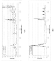
図6Aは、構造材料の一例であるABSが酸化していないとき(200℃、1分加熱)の吸収スペクトル(破線)と、酸化したとき(255℃、5分加熱)の吸収スペクトル(実線)を比較した図である。同様に、図6Bは、PP(ポリプロピレン)が酸化していないとき(160℃、1分加熱)の吸収スペクトル(破線)と、酸化したとき(255℃、5分加熱)の吸収スペクトル(実線)を比較した図である。
吸収スペクトルは、加熱後のABS又はPPの表面をSpectrum One(PerkinElmer社製;FT−IR Spectrometer)を用いて測定した。図6A,6Bから分かるように、ABS又はPPが酸化したとき、1700cm−1付近に吸収ピークが現れる。これはABS又はPPが酸化したことにより、新たに炭素と酸素の二重結合(C=O)が生成されたことに起因する。
Here, the oxidation start threshold value of the modeling material will be described.
FIG. 6A is an absorption spectrum (broken line) when ABS, which is an example of a structural material, is not oxidized (200° C., 1 minute heating) and an absorption spectrum (solid line) when oxidized (255° C., 5 minutes heating). It is the figure which compared. Similarly, FIG. 6B shows an absorption spectrum (dotted line) when PP (polypropylene) is not oxidized (160° C., 1 minute heating) and an absorption spectrum (solid line) when oxidized (255° C., 5 minutes heating). It is the figure which compared.
The absorption spectrum was measured on the surface of ABS or PP after heating using Spectrum One (manufactured by PerkinElmer; FT-IR Spectrometer). As can be seen from FIGS. 6A and 6B, when ABS or PP is oxidized, an absorption peak appears near 1700 cm −1. This is due to the formation of a new carbon-oxygen double bond (C=O) due to the oxidation of ABS or PP.
図7Aは、ABSの表面温度(加熱温度)と加熱時間を振ったときの酸化度合いを示す図である。図7Bは、PPの表面温度(加熱温度)と加熱時間を振ったときの酸化度合いを示す図である。
ABSに関しては図6Aにおいて、C=Oの吸収スペクトルのピーク値(1700cm−1付近)と、耐熱性が高く分解し難いアクリロニトリルの炭素と酸素の三重結合の吸収スペクトルのピーク値(2230cm−1付近)の比を取り、酸化度合いとして評価した。PPに関しては図6Bにおいて、C=Oの吸収スペクトルのピーク値(1700cm−1付近)と、PPを構成する炭素と水素の結合(C−H)の吸収スペクトルのピーク値(3000cm−1付近)の比を取り、酸化度合いとして評価した。
図7A,7Bから、ABSもPPも表面温度が高いほど短い加熱時間で酸化が進行していることが分かる。一方で、例えばABSやPPを215℃で加熱した場合は、ある加熱時間までは酸化が進行しないが、その後、急激に酸化が進行していることが分かる。
図8は、ABS(実線)とPP(破線)の表面温度を振ったときの、酸化が急激に進行する直前の表面温度と加熱時間の関係テーブルを示した図であり、この関係テーブルが記憶部に記憶されている。つまり、図8は、ABS(実線)とPP(破線)の酸化開始閾値を示す図であり、図8の曲線より低温側・短時間側では酸化が進行せず、高温側・超時間側では酸化が進行することを示している。ここで、本明細書では、説明の便宜上、図8に示す関係テーブル上において、造形材料のある表面温度に対する加熱時間を示す座標点を関係値という。
FIG. 7A is a diagram showing the surface temperature (heating temperature) of ABS and the degree of oxidation when the heating time is varied. FIG. 7B is a diagram showing the surface temperature (heating temperature) of PP and the degree of oxidation when the heating time is varied.
Regarding ABS, in FIG. 6A, the peak value of the absorption spectrum of C═O (around 1700 cm −1) and the peak value of the absorption spectrum of the triple bond of carbon and oxygen of acrylonitrile, which has high heat resistance and is difficult to decompose (around 2230 cm −1) ) Was taken and evaluated as the degree of oxidation. Regarding PP, in FIG. 6B, the peak value of the absorption spectrum of C═O (around 1700 cm −1) and the peak value of the absorption spectrum of the carbon-hydrogen bond (C—H) constituting PP (around 3000 cm −1). Was taken and evaluated as the degree of oxidation.
It can be seen from FIGS. 7A and 7B that the oxidation progresses in both ABS and PP in a shorter heating time as the surface temperature is higher. On the other hand, when ABS or PP is heated at 215° C., for example, the oxidation does not proceed until a certain heating time, but after that, the oxidation rapidly progresses.
FIG. 8 is a diagram showing a relation table between the surface temperature and the heating time immediately before the oxidation rapidly progresses when the surface temperatures of ABS (solid line) and PP (broken line) are changed, and this relation table is stored. It is stored in the department. That is, FIG. 8 is a diagram showing the oxidation start thresholds of ABS (solid line) and PP (broken line). Oxidation does not proceed on the low temperature side/short time side of the curve of FIG. It shows that oxidation progresses. Here, in this specification, for convenience of description, on the relation table shown in FIG. 8, a coordinate point indicating a heating time with respect to a certain surface temperature of the modeling material is referred to as a relation value.
ステップS406の薄膜化プロセスについて引き続き説明する。
制御ユニットU1は、図8に示した造形材料の酸化開始閾値を参照し、造形材料が酸化するタイミングを推測して、造形材料の関係値が酸化開始閾値に到達する前に、中間担持搬送ベルト30を駆動させる(S4063)。そして、材料層を薄膜化ユニットU4の領域外に搬送する(S4064)。一例として、ABSとPPの材料からなる材料層を薄膜化ユニットU4において200℃で加熱する場合について説明する。この場合には、図8に示した通り、ABSよりもPPの方が酸化開始閾値が短時間側である為、PPの酸化開始閾値に到達する前に、材料層を薄膜化ユニットU4の領域外に搬送する。中間担持搬送ベルト30上(搬送体上)の材料層が、加熱部材40に対向する領域から離れて、薄膜化ユニットU4の領域外に搬送されると、材料層が加熱部材40から受ける加熱の影響が低減される。このことで、中間担持搬送ベルト30上の材料層の表面温度が低下する。
The thinning process in step S406 will be continuously described.
The control unit U1 refers to the oxidation starting threshold value of the modeling material shown in FIG. 8, estimates the timing at which the modeling material oxidizes, and before the relational value of the modeling material reaches the oxidation starting threshold value, the intermediate carrying conveyor belt. 30 is driven (S4063). Then, the material layer is transported to the outside of the area of the thinning unit U4 (S4064). As an example, a case will be described in which a material layer made of ABS and PP materials is heated at 200° C. in the thinning unit U4. In this case, as shown in FIG. 8, since the oxidation start threshold of PP is shorter than that of ABS, the material layer is formed in the region of the thinning unit U4 before reaching the oxidation start threshold of PP. Transport it outside. When the material layer on the intermediate carrying belt 30 (on the carrier) is moved away from the area facing the
(積層プロセス)
その後、中間担持搬送ベルト30は同じプロセス速度のまま回転を続け、材料層を図1の矢印A方向に搬送する。そして、画像検知センサ32によってベルト上の材料層の位置を検知すると、制御ユニットU1はその検知結果を基に材料層を所定の積層位置まで搬送する(S407)。材料層が積層位置に到達するタイミングで制御ユニットU1は中間担持搬送ベルト30を停止し、材料層を積層位置に位置決めする(S408)。その後、制御ユニットU1はステージ34を上昇させ(ベルト面に近づけ)、ステージ面(1層目の場合)又はステージ表面上に形成された造形物の上面(2層目以降の場合)を中間担持搬送ベルト30上の材料層に接触させる(S409)。
(Lamination process)
After that, the intermediate carrying and conveying
この状態のまま、制御ユニットU1は、所定の温度制御シーケンスにしたがって、ヒータ33の温度を制御する。具体的には、最初に、第1の目標温度までヒータ33を加熱する第1の温度制御モードを所定時間行って、材料層を構成する造形材料を熱溶融させる(S410)。これにより材料層が軟化し、ステージ表面又はステージ上の造形物上面と、シート状の材料層とが密着する。
このとき、ステージ表面又はステージ上の造形物と材料層との間は密着した状態となっている為、空気が非常に少ない状態(酸素が少ない状態)にあり、材料層を加熱しても酸化が進行することはない。その後、第1の目標温度よりも低い第2の目標温度となるようにヒータ33を制御する第2の温度制御モードを所定時間行い、軟化した材料層を固化させる(S411)。
In this state, the control unit U1 controls the temperature of the
At this time, the surface of the stage or the modeled object on the stage and the material layer are in close contact with each other, so that there is a very small amount of air (a state where oxygen is small), and even if the material layer is heated, it is oxidized. Never progresses. Then, the second temperature control mode in which the
ここで、温度制御シーケンス、目標温度、加熱時間などは、材料画像の形成に用いられる造形材料、すなわち構造材料及びサポート材料の特性に応じて設定される。例えば、第1の温度制御モードにおける第1の目標温度は、材料画像の形成に用いられる各造形材料の融点又はガラス転移点のうち最も高い温度よりも高い値に設定される。一方、第2の温度制御モードにおける第2の目標温度は、材料画像の形成に用いられる各造形材料の結晶化温度又は非晶質材のガラス転移点のうち最も低い温度よりも低い値に設定される。
このような温度制御を行うことにより、異なる熱溶融特性をもつ複数種類の造形材料が混在した材料層の全体を共通の溶融温度領域で熱可塑化(軟化)させた後、共通の固化温度領域で材料層全体を固化させることができる。したがって、複数種類の造形材料が混在した材料層の溶融・固着を安定して行うことが可能になる。
Here, the temperature control sequence, the target temperature, the heating time, etc. are set according to the characteristics of the modeling material used for forming the material image, that is, the structural material and the support material. For example, the first target temperature in the first temperature control mode is set to a value higher than the highest temperature of the melting points or glass transition points of the respective modeling materials used for forming the material image. On the other hand, the second target temperature in the second temperature control mode is set to a value lower than the lowest temperature of the crystallization temperature of each modeling material used for forming the material image or the glass transition point of the amorphous material. To be done.
By performing such temperature control, the entire material layer in which multiple types of modeling materials having different heat melting characteristics are mixed is plasticized (softened) in the common melting temperature range, and then the common solidification temperature range is set. The entire material layer can be solidified with. Therefore, it becomes possible to stably melt and fix the material layer in which a plurality of types of modeling materials are mixed.
なお、第1の温度制御モード及び第2の温度制御モードにおいては、温度の制御域が広過ぎると、温度制御を安定化させるのに時間がかかり、積層プロセス時間が必要以上にかかってしまう。それゆえ、第1の目標温度の制御域は、材料画像の形成に用いられる各造形材料の融点又はガラス転移点のうち最も高い温度を下限温度とし、上限温度は下限温度の+50℃程度に設定するとよい。同じように、第2の目標温度の制御域は、材料画像の
形成に用いられる各造形材料の結晶化温度又は非晶質材のガラス転移点のうち最も低い温度を上限温度とし、下限温度は上限温度の−50℃程度に設定するとよい。例えば、構造材料としてABS(ガラス転移点:130℃)を用い、サポート材料としてマルトテトラオース(ガラス転移点:156℃)を用いた場合には、次のように設定するとよい。すなわち、第1の目標温度の制御域を下限156℃以上、上限206℃以下とし、第2の目標温度の制御域を下限80℃以上、上限130℃以下に設定するとよい。
第2の温度制御モード終了後、制御ユニットU1はステージ34を下降させる(S412)。以上の一連の動作により、積層プロセスは終了する。その後、次層の画像形成プロセスの実行が開始される(S401〜)。
In the first temperature control mode and the second temperature control mode, if the temperature control range is too wide, it takes time to stabilize the temperature control, and the lamination process time becomes longer than necessary. Therefore, in the control range of the first target temperature, the highest temperature of the melting points or glass transition points of the respective molding materials used for forming the material image is set as the lower limit temperature, and the upper limit temperature is set to about +50° C. of the lower limit temperature. Good to do. Similarly, in the control range of the second target temperature, the lowest temperature of the crystallization temperature of each modeling material used for forming the material image or the glass transition point of the amorphous material is the upper limit temperature, and the lower limit temperature is It is preferable to set the upper limit temperature to about -50°C. For example, when ABS (glass transition point: 130° C.) is used as the structural material and maltotetraose (glass transition point: 156° C.) is used as the support material, the following settings may be made. That is, the control range of the first target temperature may be set to the lower limit of 156° C. or more and the upper limit of 206° C. or less, and the control range of the second target temperature may be set to the lower limit of 80° C. or more and the upper limit of 130° C. or less.
After the end of the second temperature control mode, the control unit U1 lowers the stage 34 (S412). The stacking process is completed by the series of operations described above. Then, the execution of the image forming process for the next layer is started (S401-).
以上述べた画像形成プロセスと積層プロセスを必要回数繰り返すことで、ステージ34上に所望の造形物が形成される。
最後に、ステージ34から造形物を取り外し、温水などで水溶性のサポート体を除去することで、所望の造形対象物を得ることができる。サポート体を除去した後、さらに、造形対象物に対して表面処理や組立等の所定の処理を施すことにより、最終製品を得てもよい。
By repeating the image forming process and the laminating process described above a required number of times, a desired modeled object is formed on the
Finally, by removing the modeled object from the
[本実施例の利点]
以上述べた本実施例の造形装置によれば、造形材料の関係値が酸化開始閾値に到達する前に、材料層を薄膜化ユニットU4の領域外に搬送することで、材料層の表面温度を低下させることができる。材料層のうち主として空気が触れる部分である表面部分の温度を低下させることができるので、これにより、材料層の酸化を抑制することができる。材料層の酸化を抑制することで、造形材料の物性の低下や色味の変化、造形材料が中間担持搬送ベルト30にこびりつくことによって生じる積層不良を抑制することができる。
また、造形中において造形装置のキャリブレーション動作やエラー停止等が生じた場合においても、材料層が酸化する前に薄膜化ユニットU4の領域外に搬送することで酸化を抑制することができる。このため、加熱された材料層を、造形装置の動作再開時に除去することなく、そのまま積層することができる利点もある。
[Advantages of this embodiment]
According to the modeling apparatus of the present embodiment described above, the material layer is conveyed to the outside of the region of the thinning unit U4 before the relational value of the modeling material reaches the oxidation start threshold value, so that the surface temperature of the material layer is reduced. Can be lowered. Since it is possible to lower the temperature of the surface portion of the material layer that is mainly in contact with air, it is possible to suppress the oxidation of the material layer. By suppressing the oxidation of the material layer, it is possible to suppress the deterioration of the physical properties of the molding material, the change in the color tone, and the stacking failure caused by the molding material sticking to the intermediate carrying
Further, even when a calibration operation of the modeling apparatus or an error stop occurs during modeling, the material layer is transported to the outside of the thinning unit U4 before being oxidized, so that the oxidation can be suppressed. Therefore, there is also an advantage that the heated material layer can be laminated as it is without being removed when the operation of the modeling apparatus is restarted.
<実施例2>
図9は、本実施例に係る造形装置の薄膜化ユニットU4の周囲を拡大して示す概略斜視図である。
実施例1では、造形材料の関係値が酸化開始閾値に到達する前に、中間担持搬送ベルト30を駆動させて薄膜化ユニットU4の領域外に材料層を搬送した。これに対して本実施例では、造形材料の関係値が酸化開始閾値に到達する前に、薄膜化ユニットU4の加熱部材40を駆動させ、加熱部材40を材料層から離すことで、材料層の表面の温度を低下させ、酸化を抑制する点で異なる。以下、実施例1と共通する部分の説明は割愛し、本実施例に特有の構成についてのみ説明を行う。
<Example 2>
FIG. 9 is a schematic perspective view showing the periphery of the thinning unit U4 of the modeling apparatus according to this embodiment in an enlarged manner.
In Example 1, the intermediate supporting and conveying
本実施例に係る造形装置の加熱部材40は、駆動装置401により中間担持搬送ベルト30の表面に対して垂直方向に移動可能に構成されている。そして加熱部材40は、駆動装置401の駆動により中間担持搬送ベルト30上の材料層を加熱する通常位置(図9に40aで示す位置)と、中間担持搬送ベルト30上の材料層に対し通常位置よりも離れた離間位置(図9に40bで示す位置)との間を移動する。
駆動装置401はアクチュエータであり、制御部U1からの指示に従って、中間担持搬送ベルト30の表面に対して垂直方向に加熱部材40を移動させる。駆動装置401としては、圧電素子、ネジ機構、シリンダ機構、ピストン機構、モータ等を使用することができる。
The
The
本実施例では、制御部U1は、薄膜化ユニットU4に搬送された材料層の表面温度と加
熱時間を測定し、造形材料の酸化開始閾値を参照して、造形材料の関係値が酸化開始閾値に到達する前に駆動装置401を駆動して、加熱部材40を移動させる。このとき、制御部U1は、駆動装置401を駆動して、中間担持搬送ベルト30の表面に対して垂直方向に加熱部材40を移動させる。
これにより、加熱部材40は、図9に40aで示す通常位置(材料層を加熱する位置)から、図9に40bで示す離間位置に移動する。
その後、材料層が薄膜化ユニットU4の領域外に搬送されると、加熱部材40は、図9に40aで示す通常位置に戻る。
以上述べた本実施例の構成によっても、実施例1と同様の作用効果を奏することができる。
In the present embodiment, the control unit U1 measures the surface temperature and the heating time of the material layer conveyed to the thinning unit U4, refers to the oxidation start threshold of the modeling material, and refers to the oxidation start threshold of the modeling material. The
As a result, the
Then, when the material layer is conveyed to the outside of the area of the thinning unit U4, the
With the configuration of the present embodiment described above, the same operational effect as that of the first embodiment can be obtained.
<実施例3>
図10は、本実施例に係る造形装置の薄膜化ユニットU4の周囲を拡大して示す概略断面図である。実施例2では、造形材料の関係値が酸化開始閾値に到達する前に、加熱部材40を材料層から離間させることで、材料層の表面温度を低下させた。これに対して本実施例では、造形材料の関係値が酸化開始閾値に到達する前に、冷却機構44を駆動させて、材料層の表面の温度を低下させる点で異なる。以下、実施例1,2と共通する部分の説明は割愛し、本実施例に特有の構成についてのみ説明を行う。
<Example 3>
FIG. 10 is an enlarged schematic cross-sectional view showing the periphery of the thinning unit U4 of the modeling apparatus according to this embodiment. In Example 2, the surface temperature of the material layer was lowered by separating the
制御部U1は、薄膜化ユニットU4に搬送された材料層の表面温度と加熱時間を測定し、造形材料の酸化開始閾値を参照して、造形材料の関係値が酸化開始閾値に到達する前に、冷却機構44を駆動させる。冷却機構としては、空冷方式を用いることができ、ファンによって外気を材料層に向けて送るものであるとよく、冷媒等によって冷却された空気を材料層に向けて送るものであってもよい。
その後、材料層が薄膜化ユニットU4の領域外に搬送されると、冷却機構44の駆動は停止される。
以上述べた本実施例の造形装置によれば、造形材料の関係値が酸化開始閾値に到達する前に、空冷方式によって材料層の表面の温度を低下させることができ、材料層の酸化を抑制することができる。したがって、実施例1,2と同様の作用効果を奏することができる。
The control unit U1 measures the surface temperature and the heating time of the material layer conveyed to the thinning unit U4, refers to the oxidation start threshold of the modeling material, and before the relational value of the modeling material reaches the oxidation start threshold. , Drive the
After that, when the material layer is conveyed to the outside of the area of the thinning unit U4, the driving of the
According to the modeling apparatus of the present embodiment described above, the temperature of the surface of the material layer can be lowered by the air cooling method before the relational value of the modeling material reaches the oxidation start threshold value, and the oxidation of the material layer is suppressed. can do. Therefore, the same effects as those of the first and second embodiments can be obtained.
<実施例4>
図11A,11Bは、本実施例に係る造形装置の薄膜化ユニットU4の周囲を拡大して示す概略断面図である。本実施例では、材料層を冷却する冷却部材45を、中間担持搬送ベルト30上の材料層に対して接離可能に備えることを特徴とする。以下、実施例1〜3と共通する部分の説明は割愛し、本実施例に特有の構成についてのみ説明を行う。
図11A,11Bに示すように、本実施例では、薄膜化ユニットU4は、冷却部材45と、駆動装置451を備える。駆動装置451はアクチュエータであり、制御部U1からの指示に従って、冷却部材45を中間担持搬送ベルト30の表面に対して垂直方向に駆動する。駆動装置451としては、圧電素子、ネジ機構、シリンダ機構、ピストン機構、モータ等を使用することができる。
<Example 4>
11A and 11B are schematic cross-sectional views showing the periphery of the thinning unit U4 of the modeling apparatus according to this embodiment in an enlarged manner. The present embodiment is characterized in that a cooling
As shown in FIGS. 11A and 11B, in this embodiment, the thinning unit U4 includes a cooling
冷却部材45は、金属等からなる板状の部材であり、駆動装置451に駆動されることで、中間担持搬送ベルト30上の材料層に対して接離可能に配置されている。冷却部材45は、駆動装置451の駆動により中間担持搬送ベルト30の表面に対して垂直方向に移動可能であり、図11Aに示す待機位置と、図11Bに示す、材料層に当接する当接位置(冷却位置)との間を移動する。冷却部材45は、材料層に当接したときに、冷却部材45の平面部分が材料層に当接するように配置されている。造形装置の動作時において、冷却部材45は、材料層に当接したときに材料層の表面温度を低下させることができるように冷却された状態にある。このとき、冷却部材45は、放熱によって冷却された状態にあ
るとよいが、冷却機構を備え、空冷又は冷媒によって冷却されるものであってもよい。冷却部材45の表面は、耐熱性と高離型性を備えた材料であることが好ましく、パーフルオロアルコキシアルカン(PFA)やポリテトラフルオロエチレン(PTFE)等のフッ素
樹脂を用いることができる。
The cooling
制御部U1は、薄膜化ユニットU4に搬送された材料層の表面温度と加熱時間を測定し、造形材料の酸化開始閾値を参照して、造形材料の関係値が酸化開始閾値に到達する前に、冷却部材45を図11Aに示す待機位置から、図11Bに示す当接位置に移動させる。
その後、(制御部U1)は、中間担持搬送ベルト30を駆動する前に、冷却部材45を図11Aに示す待機位置に戻す。冷却部材45と材料層が離間した後、制御部U1は、中間担持搬送ベルト30を駆動させ、材料層を積層位置に搬送する。
以上述べた本実施例の構成によっても、造形材料の関係値が酸化開始閾値に到達する前に、材料層を冷却部材45によって冷却することで、材料層の表面温度を低下させ、材料層の酸化を抑制することができる。したがって、実施例1〜3と同様の作用効果を奏することができる。
The control unit U1 measures the surface temperature and the heating time of the material layer conveyed to the thinning unit U4, refers to the oxidation start threshold of the modeling material, and before the relational value of the modeling material reaches the oxidation start threshold. , The cooling
After that, the (control unit U1) returns the cooling
Also with the configuration of the present embodiment described above, the surface temperature of the material layer is lowered by cooling the material layer with the cooling
以上、本発明の好ましい実施例1〜4について説明したが、本発明はこれらの実施例に限定されず、その要旨の範囲内で種々の変形および変更が可能である。
例えば、上述の実施例では、複数の中間担持搬送ベルトを使用したが、これに限るものではなく、画像形成ユニットU2で中間担持搬送ベルト30に材料層を直接形成するように構成して、中間担持搬送ベルト11を省く構成にしてもよい。
また、上述の実施例においては、薄膜化ユニットU4において、中間担持搬送ベルト30上の材料層を薄膜化するために加熱する際に、材料層が酸化してしまうことを抑制する構成について説明した。しかし、ヒータ33により加熱する前の材料層を予備加熱する形態であれば、薄膜化を目的とする加熱に限らず、本発明を適用することで、材料層の酸化を抑制することができる。すなわち、中間担持搬送ベルト30上の材料層をステージ34上に積層するときに当該材料層に対して行われるヒータ33による加熱の前に、当該材料層を予備加熱する構成において、本発明を好適に適用することができる。なお、予備加熱部における設定温度は、装置の仕様(造形物の作製スピード等)に応じて適宜設定されている。
The
For example, although a plurality of intermediate carrying belts are used in the above-described embodiments, the present invention is not limited to this, and the image forming unit U2 is configured to directly form a material layer on the
In addition, in the above-described embodiment, the configuration in which the material layer on the intermediate carrying and conveying
また、上述の実施例1では、中間担持搬送ベルト30の駆動を停止した状態で、薄膜化プロセスを行うものであったが、これに限るものではない。実施例2〜4において薄膜化プロセスを行う場合、中間担持搬送ベルト30の駆動を停止した状態であってもよいし、中間担持搬送ベルト30を駆動させたままの状態であってもよい。例えば造形装置が次のような構成の場合に、中間担持搬送ベルト30を駆動させたままの状態で薄膜化プロセスを行うとよい。それは、造形装置が、材料層の積層時に、ステージ34と中間担持搬送ベルト30との間に材料層を挟んだ状態で、ステージ34が中間担持搬送ベルト30とともに移動可能に構成されている場合である。中間担持搬送ベルト30を駆動させたままの状態で薄膜化プロセスを行う場合には、予備加熱部を通過する時間を加熱時間とすることができる。
また、上述の実施例では、材料層の表面温度を温度測定部41により測定したが、これに限るものではない。例えば、加熱部材40の設定温度と、材料層の加熱時間と、材料層の表面温度との関係を制御部U1の記憶部に記憶させ、加熱時間を測定することで、材料層の表面温度を取得するように構成されるものであってもよい。
なお、加熱部材40の設定温度は、適宜変更されるものであってもよい。例えば、薄膜化プロセスにおいて、造形材料の関係値が酸化開始閾値に到達する前に、上述の各実施例における、材料層の表面温度を低下させる動作とともに、加熱部材40の設定温度を下げるか、加熱部材40の加熱動作を停止させてもよい。これにより、材料層の表面温度をより効率よく低下させることができる。
Further, in the above-described first embodiment, the thinning process is performed with the driving of the intermediate carrying
Further, in the above-mentioned embodiment, the surface temperature of the material layer is measured by the
The set temperature of the
また、上述の実施例では、造形材料が2種類の場合について説明したが、これに限るものではない。造形材料は造形装置の仕様に応じて複数種類用いることができる。この場合には、複数種類の造形材料にそれぞれ応じて、図8の酸化開始閾値を示す関係テーブルが記憶部に記憶される。そして、造形装置の動作時には、材料層の形成に用いる造形材料の種類に応じた関係テーブルの酸化開始閾値を参照して、造形材料が酸化するタイミングを推測し、造形材料の関係値が酸化開始閾値に到達する前に、材料層の表面温度を低下させる上述の動作を行う。1層分の材料層が、複数の造形材料で形成されている場合には、当該複数の造形材料のなかで酸化するタイミングが最も早いと推測される造形材料の関係値が酸化開始閾値に到達する前に、材料層の表面温度を低下させる上述の動作を行う。
このような造形材料の種類に応じた関係テーブルは、造形材料が収容されたカートリッジを交換したときに、カートリッジ内の造形材料の種類に応じて自動的に切り替えられて設定されるものであるとよい。また、図8に示す関係テーブルは、制御ユニットU1の記憶部に記憶されるものであるが、これに限らず、カートリッジ側に設けられた記憶部に記憶されるものであってもよい。
また、上述した各実施例を可能な限り組み合わせることができる。例えば、上述した実施例1〜3を組み合わせてもよく、実施例2〜4を組み合わせてもよい。
Further, in the above-described embodiment, the case where there are two types of molding materials has been described, but the present invention is not limited to this. Plural kinds of molding materials can be used according to the specifications of the molding apparatus. In this case, the relationship table indicating the oxidation start threshold value of FIG. 8 is stored in the storage unit for each of the plurality of types of modeling materials. When the modeling apparatus is operating, the oxidation start threshold of the relationship table corresponding to the type of modeling material used to form the material layer is referred to, the timing at which the modeling material oxidizes is estimated, and the relationship value of the modeling material starts to oxidize. Before reaching the threshold value, the above-mentioned operation of lowering the surface temperature of the material layer is performed. When the material layer for one layer is formed of a plurality of modeling materials, the relation value of the modeling material that is estimated to be the earliest to be oxidized among the plurality of modeling materials reaches the oxidation start threshold value. Before this, the above-mentioned operation of lowering the surface temperature of the material layer is performed.
Such a relationship table according to the type of modeling material is set to be automatically switched according to the type of modeling material in the cartridge when the cartridge containing the modeling material is replaced. Good. Further, the relationship table shown in FIG. 8 is stored in the storage unit of the control unit U1, but not limited to this, and may be stored in the storage unit provided on the cartridge side.
Further, the above-described respective embodiments can be combined as much as possible. For example, the first to third embodiments described above may be combined, or the second to fourth embodiments may be combined.
1…造形装置、10…画像形成部、30…中間担持搬送ベルト、34…ステージ、40…加熱部材、U1…制御ユニット、U141…薄膜温度取得部、U142…薄膜加熱時間取得部
DESCRIPTION OF
Claims (6)
造形対象物のスライス形状データに基づいて前記搬送体の上に造形材料を配置する材料配置工程と、
前記搬送体上の前記造形材料が前記積層位置に到達する前に、酸素を含む雰囲気中で前記造形材料を加熱する加熱工程と、
加熱された前記造形材料を前記積層位置に移動させ、前記造形材料を前記搬送体と前記ステージとで挟んで前記ステージの上に転写する転写工程と、
を有し、
前記加熱工程において、前記造形材料の加熱状態は、前記造形材料が酸化しない様に、前記造形材料の温度および加熱時間に基づいて制御される、
ことを特徴とする立体物の製造方法。 A method of manufacturing a three-dimensional object , wherein a modeling material arranged on a carrier is conveyed to a stacking position by the carrier and laminated on a stage ,
A material placement step of placing a shaping material on the carrier based on the slice shape data of the shaping target ,
A heating step of heating the modeling material in an atmosphere containing oxygen before the modeling material on the carrier reaches the stacking position ;
A transfer step of moving the heated modeling material to the stacking position, sandwiching the modeling material between the carrier and the stage, and transferring the molding material onto the stage ;
Have
In the heating step, the heating state of the molding material is controlled based on the temperature and the heating time of the molding material so that the molding material is not oxidized.
A method for manufacturing a three-dimensional object characterized by the above.
造形対象物のスライス形状データに基づいて前記搬送体の上に前記造形材料を配置する材料配置部と、
前記材料配置部と前記積層位置との間に設けられ、前記搬送体の上の前記造形材料を加熱する加熱部と、
前記加熱部によって加熱された前記造形材料の温度を取得する温度取得部と、
前記造形材料の温度が所定の時間に達してからの加熱時間を計測する時間測定部と、
前記搬送体により前記積層位置に搬送された前記造形材料が転写されるステージと、
前記加熱部および前記搬送体を制御する制御部と、
を有し、
前記制御部は、前記造形材料が酸化しない様に、前記温度取得部で取得した前記造形材料の温度および前記時間測定部で計測した加熱時間に基づいて、前記加熱部または前記搬送体を制御して前記加熱部による前記造形材料の加熱状態を制御する、
ことを特徴とする造形装置。 A modeling apparatus for manufacturing a three-dimensional object by transporting a modeling material arranged on a carrier to a stacking position by the carrier and stacking on a stage ,
A material placement portion for positioning the build material on the transfer body on the basis of the slice shape data of the shaped object,
A heating unit which is provided between the material placement unit and the stacking position and heats the modeling material on the carrier.
A temperature acquisition unit for acquiring the temperature of the modeling material heated by the heating unit,
A time measuring unit that measures the heating time after the temperature of the molding material reaches a predetermined time,
A stage to which the modeling material transferred to the stacking position by the transfer body is transferred,
A control unit for controlling the heating unit and the carrier ,
Have
Wherein, as the building material is not oxidized, on the basis of the heating time measured by the temperature and the time measuring unit of the said building material obtained by the temperature acquiring unit, to control the heating unit or the carrier Control the heating state of the modeling material by the heating unit ,
A modeling device characterized in that
前記制御部は、前記温度取得部で取得した前記造形材料の温度と、前記酸化特性と、前記加熱時間と、に基づいて、前記加熱部または前記搬送体を制御する、 The control unit controls the heating unit or the carrier based on the temperature of the modeling material acquired by the temperature acquisition unit, the oxidation property, and the heating time,
ことを特徴とする請求項3または4に記載の造形装置。The modeling apparatus according to claim 3 or 4, characterized in that.
前記制御部は、前記造形材料の酸化が始まる前に、前記造形材料と前記加熱部材との距離が長くなるように前記加熱部材を移動させる、
ことを特徴とする請求項3から5のいずれか1項に記載の造形装置。
The molding device further comprises a moving mechanism for moving the heating member for the heating unit is provided,
Wherein, before the oxidation of the build material begins, the distance between the heating member and the build material to move said heating element to be longer,
The modeling apparatus according to any one of claims 3 to 5, wherein:
Priority Applications (2)
| Application Number | Priority Date | Filing Date | Title |
|---|---|---|---|
| JP2016025809A JP6732466B2 (en) | 2016-02-15 | 2016-02-15 | Modeling apparatus and modeling method |
| US15/427,405 US10357956B2 (en) | 2016-02-15 | 2017-02-08 | Shaping apparatus and shaping method |
Applications Claiming Priority (1)
| Application Number | Priority Date | Filing Date | Title |
|---|---|---|---|
| JP2016025809A JP6732466B2 (en) | 2016-02-15 | 2016-02-15 | Modeling apparatus and modeling method |
Publications (3)
| Publication Number | Publication Date |
|---|---|
| JP2017144573A JP2017144573A (en) | 2017-08-24 |
| JP2017144573A5 JP2017144573A5 (en) | 2019-03-28 |
| JP6732466B2 true JP6732466B2 (en) | 2020-07-29 |
Family
ID=59560051
Family Applications (1)
| Application Number | Title | Priority Date | Filing Date |
|---|---|---|---|
| JP2016025809A Expired - Fee Related JP6732466B2 (en) | 2016-02-15 | 2016-02-15 | Modeling apparatus and modeling method |
Country Status (2)
| Country | Link |
|---|---|
| US (1) | US10357956B2 (en) |
| JP (1) | JP6732466B2 (en) |
Families Citing this family (6)
| Publication number | Priority date | Publication date | Assignee | Title |
|---|---|---|---|---|
| JP6922653B2 (en) * | 2017-10-27 | 2021-08-18 | 株式会社リコー | Modeling method and modeling system |
| DE102017219795A1 (en) * | 2017-11-08 | 2019-05-09 | Robert Bosch Gmbh | Apparatus and method for generatively manufacturing an object composed of a plurality of cross-sections and a three-dimensional object |
| US11951679B2 (en) | 2021-06-16 | 2024-04-09 | General Electric Company | Additive manufacturing system |
| US11731367B2 (en) | 2021-06-23 | 2023-08-22 | General Electric Company | Drive system for additive manufacturing |
| US11826950B2 (en) | 2021-07-09 | 2023-11-28 | General Electric Company | Resin management system for additive manufacturing |
| US11813799B2 (en) | 2021-09-01 | 2023-11-14 | General Electric Company | Control systems and methods for additive manufacturing |
Family Cites Families (7)
| Publication number | Priority date | Publication date | Assignee | Title |
|---|---|---|---|---|
| DE102005015870B3 (en) * | 2005-04-06 | 2006-10-26 | Eos Gmbh Electro Optical Systems | Device and method for producing a three-dimensional object |
| JP5408207B2 (en) * | 2011-08-25 | 2014-02-05 | コニカミノルタ株式会社 | Solid object shaping apparatus and control program |
| US20130053995A1 (en) * | 2011-08-25 | 2013-02-28 | Konica Minolta Business Technologies, Inc. | Three-dimensional object molding apparatus and control program |
| WO2013044047A1 (en) * | 2011-09-23 | 2013-03-28 | Stratasys, Inc. | Layer transfusion for additive manufacturing |
| US8879957B2 (en) * | 2011-09-23 | 2014-11-04 | Stratasys, Inc. | Electrophotography-based additive manufacturing system with reciprocating operation |
| JP2015182425A (en) | 2014-03-26 | 2015-10-22 | セイコーエプソン株式会社 | Method for manufacturing three-dimensional molded article and three-dimensional molded article |
| JP2015229315A (en) * | 2014-06-06 | 2015-12-21 | シャープ株式会社 | Lamination molding device and lamination molding method |
-
2016
- 2016-02-15 JP JP2016025809A patent/JP6732466B2/en not_active Expired - Fee Related
-
2017
- 2017-02-08 US US15/427,405 patent/US10357956B2/en not_active Expired - Fee Related
Also Published As
| Publication number | Publication date |
|---|---|
| JP2017144573A (en) | 2017-08-24 |
| US20170232673A1 (en) | 2017-08-17 |
| US10357956B2 (en) | 2019-07-23 |
Similar Documents
| Publication | Publication Date | Title |
|---|---|---|
| JP6732466B2 (en) | Modeling apparatus and modeling method | |
| WO2016084350A1 (en) | Forming apparatus, three-dimensional forming method, and object formed by using the method | |
| US9423756B2 (en) | Electrophotography-based additive manufacturing system with reciprocating operation | |
| US11052609B2 (en) | Molding system, data processing device for generating molding data, and method of manufacturing three-dimensional object | |
| JP5831740B2 (en) | Fixing device and image forming apparatus | |
| US20170173874A1 (en) | Electrophotography-based additive manufacturing with support structure and boundary | |
| WO2016084367A1 (en) | Three-dimensional shaping apparatus and three-dimensional shaped article manufacturing method | |
| US10005230B2 (en) | Electrostatic 3-D printer controlling layer thickness using feedback loop to transfer device | |
| JP2017105088A (en) | Molding apparatus | |
| WO2016084348A1 (en) | Three-dimensional modeling apparatus, three-dimensional modeling method, and article manufacturing method | |
| JP2018016005A (en) | Molding apparatus | |
| US10996602B2 (en) | Height control in selective deposition based additive manufacturing of parts | |
| JP2016107629A (en) | Three-dimensional molding apparatus and method for manufacturing three-dimensional molded object | |
| WO2016084913A1 (en) | Shaping device and method for fabricating three-dimensional object | |
| JP2016107630A (en) | Molding device, production method, and molded object molded by the same | |
| JP2018176428A (en) | Three-dimensional shaping apparatus | |
| JP6700958B2 (en) | Modeling apparatus and modeling method | |
| JP2018020474A (en) | Molding device and molding method | |
| JP2016107634A (en) | Molding device and three-dimensional object production method | |
| JP2017177813A (en) | Molding apparatus | |
| US20190056688A1 (en) | Forming apparatus, and manufacturing method of three-dimensional object | |
| US20220227040A1 (en) | Selective deposition-based additive manufacturing device and method of printing 3d parts with semi-crystalline materials | |
| JP6758899B2 (en) | Modeling equipment | |
| US11446862B2 (en) | Sacrificial layers in selective deposition-based additive manufacturing of parts | |
| JP7322117B2 (en) | Modeling apparatus, data processing apparatus for generating modeling data, and method for manufacturing three-dimensional object |
Legal Events
| Date | Code | Title | Description |
|---|---|---|---|
| RD02 | Notification of acceptance of power of attorney |
Free format text: JAPANESE INTERMEDIATE CODE: A7422 Effective date: 20181116 |
|
| A521 | Request for written amendment filed |
Free format text: JAPANESE INTERMEDIATE CODE: A523 Effective date: 20190214 |
|
| A621 | Written request for application examination |
Free format text: JAPANESE INTERMEDIATE CODE: A621 Effective date: 20190214 |
|
| A977 | Report on retrieval |
Free format text: JAPANESE INTERMEDIATE CODE: A971007 Effective date: 20191216 |
|
| A131 | Notification of reasons for refusal |
Free format text: JAPANESE INTERMEDIATE CODE: A131 Effective date: 20200114 |
|
| A521 | Request for written amendment filed |
Free format text: JAPANESE INTERMEDIATE CODE: A523 Effective date: 20200313 |
|
| TRDD | Decision of grant or rejection written | ||
| A01 | Written decision to grant a patent or to grant a registration (utility model) |
Free format text: JAPANESE INTERMEDIATE CODE: A01 Effective date: 20200609 |
|
| A61 | First payment of annual fees (during grant procedure) |
Free format text: JAPANESE INTERMEDIATE CODE: A61 Effective date: 20200708 |
|
| R151 | Written notification of patent or utility model registration |
Ref document number: 6732466 Country of ref document: JP Free format text: JAPANESE INTERMEDIATE CODE: R151 |
|
| LAPS | Cancellation because of no payment of annual fees |