EP4344529A1 - Harvesting machine with a harvesting device and method for operating the harvesting machine - Google Patents
Harvesting machine with a harvesting device and method for operating the harvesting machine Download PDFInfo
- Publication number
- EP4344529A1 EP4344529A1 EP23196004.8A EP23196004A EP4344529A1 EP 4344529 A1 EP4344529 A1 EP 4344529A1 EP 23196004 A EP23196004 A EP 23196004A EP 4344529 A1 EP4344529 A1 EP 4344529A1
- Authority
- EP
- European Patent Office
- Prior art keywords
- mulching
- harvesting
- unit
- overload
- harvesting machine
- Prior art date
- Legal status (The legal status is an assumption and is not a legal conclusion. Google has not performed a legal analysis and makes no representation as to the accuracy of the status listed.)
- Pending
Links
- 238000003306 harvesting Methods 0.000 title claims abstract description 191
- 238000000034 method Methods 0.000 title claims description 11
- 239000002689 soil Substances 0.000 claims abstract description 27
- 238000005520 cutting process Methods 0.000 claims abstract description 23
- 230000005540 biological transmission Effects 0.000 claims description 34
- 238000003754 machining Methods 0.000 claims description 20
- 241000196324 Embryophyta Species 0.000 description 16
- 239000004575 stone Substances 0.000 description 7
- 238000001514 detection method Methods 0.000 description 6
- 238000004364 calculation method Methods 0.000 description 5
- 230000007423 decrease Effects 0.000 description 5
- 239000000463 material Substances 0.000 description 4
- 238000012423 maintenance Methods 0.000 description 3
- 238000011144 upstream manufacturing Methods 0.000 description 3
- 240000008042 Zea mays Species 0.000 description 2
- 230000003247 decreasing effect Effects 0.000 description 2
- 235000005940 Centaurea cyanus Nutrition 0.000 description 1
- 241000208818 Helianthus Species 0.000 description 1
- 235000003222 Helianthus annuus Nutrition 0.000 description 1
- 206010061217 Infestation Diseases 0.000 description 1
- 241000346285 Ostrinia furnacalis Species 0.000 description 1
- 241000607479 Yersinia pestis Species 0.000 description 1
- 235000005824 Zea mays ssp. parviglumis Nutrition 0.000 description 1
- 235000002017 Zea mays subsp mays Nutrition 0.000 description 1
- 238000004026 adhesive bonding Methods 0.000 description 1
- 238000010276 construction Methods 0.000 description 1
- 235000005822 corn Nutrition 0.000 description 1
- 230000001419 dependent effect Effects 0.000 description 1
- 239000000428 dust Substances 0.000 description 1
- 239000004459 forage Substances 0.000 description 1
- 230000007774 longterm Effects 0.000 description 1
- 230000007257 malfunction Effects 0.000 description 1
- 239000002184 metal Substances 0.000 description 1
- 238000012544 monitoring process Methods 0.000 description 1
- 238000001556 precipitation Methods 0.000 description 1
- 238000003825 pressing Methods 0.000 description 1
- 238000003466 welding Methods 0.000 description 1
Images


Classifications
-
- A—HUMAN NECESSITIES
- A01—AGRICULTURE; FORESTRY; ANIMAL HUSBANDRY; HUNTING; TRAPPING; FISHING
- A01D—HARVESTING; MOWING
- A01D34/00—Mowers; Mowing apparatus of harvesters
- A01D34/835—Mowers; Mowing apparatus of harvesters specially adapted for particular purposes
- A01D34/8355—Mowers; Mowing apparatus of harvesters specially adapted for particular purposes for cutting up or crushing remaining standing stalks, e.g. stubble
-
- A—HUMAN NECESSITIES
- A01—AGRICULTURE; FORESTRY; ANIMAL HUSBANDRY; HUNTING; TRAPPING; FISHING
- A01D—HARVESTING; MOWING
- A01D43/00—Mowers combined with apparatus performing additional operations while mowing
- A01D43/08—Mowers combined with apparatus performing additional operations while mowing with means for cutting up the mown crop, e.g. forage harvesters
- A01D43/081—Mowers combined with apparatus performing additional operations while mowing with means for cutting up the mown crop, e.g. forage harvesters specially adapted for ensilage of maize
-
- A—HUMAN NECESSITIES
- A01—AGRICULTURE; FORESTRY; ANIMAL HUSBANDRY; HUNTING; TRAPPING; FISHING
- A01D—HARVESTING; MOWING
- A01D45/00—Harvesting of standing crops
- A01D45/02—Harvesting of standing crops of maize, i.e. kernel harvesting
- A01D45/021—Cornheaders
Definitions
- mulching devices are often used to shred the plant stems that remain in the ground. Crushing promotes rotting. Furthermore, the shredded plant stems can be better mixed in during subsequent soil cultivation. In addition, pest infestation, such as corn borers, can be prevented.
- Such mulching devices are regularly arranged on a harvesting device, in particular a harvesting header, and are arranged downstream of a cutting tool of the harvesting device provided for harvesting the crop in a crop flow direction. They are arranged close to the ground and therefore repeatedly come into contact with obstacles such as stones or uneven ground. By hitting Such obstacles not only put a strain on the processing tool of the mulching devices, but also on their drive train, in particular the gearbox and/or clutches of the drive train, so that damage can occur or at least wear and tear occurs.
- EP 3 881 665 A1 an overload protection for a mulching device, in which a connecting means is provided with which the processing tool is attached to the mulching device. If an overload occurs, it is intended that the connecting means will tear. This predetermined break does not damage the components of the drive train of the mulcher, but the mulcher needs to be repaired in order to continue driving in the field. In addition, the tool and its drive train are loaded until the connecting means breaks, so that wear still occurs on the tool and the drive train.
- the publication EP 3 391 724 B1 discloses a self-propelled harvester with a harvest header on which a mulching device is arranged.
- the harvester has a speed sensor for detecting the advance speed. It is designed to move the mulching device into a non-operational position when the forward speed falls below a minimum forward speed or when the harvester moves backwards. This means that the mulcher is less likely to get caught in the field soil.
- the object of the present invention is to create a harvesting machine with a harvesting device on which a mulching unit is arranged, in which wear on the mulching unit, the drive train of the mulching unit and / or the harvesting device is reduced and / or a service life of the mulching unit drivetrain and/or the harvesting device is increased, and which is easy to handle for the driver, the mulching unit being inexpensive to produce and/or operate.
- the harvesting machine is characterized in that the sensor is provided for detecting an overload acting on the processing tool, and the control unit is configured to pivot the mulching unit into a raised position relative to the working position when the overload is detected, and/or the sensor is provided for detecting a crop flow in the harvesting machine, and the control unit is configured to pivot the mulching unit into the raised position relative to the working position when the crop flow is reduced or absent.
- the processing tool of the mulching unit can be lifted over the obstacle when it comes into contact with an obstacle, such as a stone or an uneven ground. This will automatically lift it out of the blockage area. Since the mulching unit is automatically lifted out of the blockage area, the overload is eliminated very quickly and the harvesting device is only loaded for a very short time. In addition, the driver does not have to intervene, can focus his attention on the further harvesting process and is not stressed or distracted by watching the mulching unit.
- the processing tool If the processing tool has already penetrated the field soil, it will be lifted out of it very quickly. As a result, wear on the machining tool only occurs for a very short time, the wear is therefore low and the service life of the machining tool is long. In addition, the overload does not require any maintenance work in the field, as the mulching unit can continue to operate after the overload occurs.
- the mulching unit By detecting a decreasing or lacking crop flow, the mulching unit is only pivoted into the working position during field operation as long as crops are being harvested. When no crops are being harvested, the mulching unit is pivoted into the raised position relative to the working position, for example when the harvester is at a standstill or during turning maneuvers, particularly on headlands and/or when reversing. Since the mulching unit is pivoted from the working position into the raised position when the crop flow decreases or fails, unnecessary operation of the mulching unit is avoided, so that no overload can occur on the processing tool. It can also be provided that the processing tool is not operated when the mulching unit is in the raised position. This reduces the power requirement of the harvester.
- the extended service life also reduces the (maintenance) costs for the mulching unit, at least in the long term or even in the medium term.
- the harvesting device is a harvesting attachment for a harvesting machine, in particular a self-propelled one. As such, it is preferably arranged at the front of the harvester.
- the mulching unit can also be used for other harvesting devices that can be attached to a tractor or mounted on the rear, for example.
- the sensor is provided for detecting the overload and is designed as a speed sensor or as a torque sensor which is arranged on the mulching unit.
- the overload can then be detected directly on the mulching unit, in particular on or near the processing tool. Due to the large number of speed sensors and torque sensors used in technical devices, such sensors are available very inexpensively and the detection of the overload in the mulching unit can therefore be implemented very cost-effectively.
- the mulching unit comprises a transmission which is connected on the input side to a drive train of the harvesting device and/or the harvesting machine, and which comprises a tool-side output for driving the processing tool, the sensor being arranged in the transmission. Due to the arrangement of the sensor in the gearbox, the sensor is arranged close to the processing tool. In a preferred embodiment, a sensor that is already provided for detecting the drive speed of the transmission or the mulching unit is used as the sensor. This means there are no costs for an additional sensor.
- the harvesting machine preferably has a plurality of mulching units, with a gearbox being provided for each of the mulching units, with each of the mulching units comprising a sensor for detecting the overload. This means that any overload that occurs can be recorded separately in each mulching unit.
- the transmissions of two or more of the mulching units are connected to one another by means of cardan shafts. This means they are arranged in a row one behind the other.
- the gearboxes of the mulching units preferably each have an output for driving an adjacent gearbox of an adjacent mulching unit.
- the gears are each designed as a T-gear.
- they each preferably have a transmission shaft passing through them, which can be driven at one end and which is used at the other end to drive the adjacent transmission.
- the ends of the transmission shaft are preferably connected to the cardan shafts by means of a cardan joint in order to enable a spatial offset between the transmissions.
- a mulching unit can be arranged spatially offset relative to its adjacent mulching unit or units, in particular offset in height.
- the cardan shafts therefore enable each of the mulching units to be raised and/or lowered independently of an adjacent mulching unit.
- the harvesting device can have one or more drive trains to drive the mulching units.
- at least two mulching units that are connected to the same drive train and interconnected form a group.
- the mulching units of the same group in particular in In relation to the torque and/or the speed of their processing tools, they are monitored together. Since the mulching units in the group are connected to one another by drive, even if the sensor in one of the mulching units fails, overload detection can be carried out by the other, particularly neighboring, mulching units that are connected by drive. This essentially enables redundant overload detection.
- This type of monitoring can also detect a failure or malfunction of a mulching unit in the group or one of the sensors in the mulching units.
- the mulching units can be raised separately, in particular depending on the hydraulic power available, or the mulching units of a group can be raised together from the working position to the raised position.
- only one sensor can be provided to monitor the overload of the mulching units of such a group, with the mulching units being pivoted together from the working position to the raised position when the overload occurs.
- the harvesting device of the harvesting machine preferably comprises at least two sections, with each of the sections being assigned at least two mulching units, preferably more, in particular of the same group.
- the mulching units of the sections are preferably arranged evenly distributed over a width of the sections.
- the sections of the harvesting device can be provided so that they can be adjusted relative to one another, so that they can be reversibly moved from a working position to a transport position, for example by an adjustment mechanism.
- at least one drive train is provided for each of the sections of the harvesting device to drive the mulching units.
- the mulching units of each section also particularly preferably form a group.
- the harvesting device also preferably has a main transmission which connects the drive trains to a power take-off shaft of the harvesting machine in a way that receives power.
- control unit is set up to, when an overload occurs on a mulching unit, this mulching unit separately or together the mulching units of the section in which it is arranged, or together the mulching units of the group to which it belongs, from the working position to pivot into the raised position.
- the transmission has an overload clutch which is designed to drive-separate the tool-side output of the transmission from the rest of the drive train.
- the overload clutch therefore not only serves to protect the overloaded mulching unit. At the same time, it also protects all other drive trains and/or transmissions of the harvesting device and/or the harvesting machine that are connected to it. As a result, the processing tool of the mulching unit and/or the harvesting device is less likely to be damaged than with conventional mulching units.
- the overload causes wear on the overload clutch.
- the overload clutch can be designed in such a way that the wear caused by lifting the mulching unit is very minimal.
- the processing tool can start up automatically once the overload or blockage has been overcome. This also means that the driver is not burdened by an overload that occurs on one of the mulching units.
- the harvesting machine preferably also has a read-only memory in which the threshold value is stored.
- the threshold value is adjustable, in particular by the driver of the harvesting machine or a technician, in particular on an operator console.
- the control unit can also be set up to detect obstacles and to store this data in the read-only memory. Preferably, at least the type of obstacle, in particular stone or uneven ground, and its position are detected.
- the sensor is provided for detecting the crop flow.
- a crop flow sensor that is already present in the harvesting machine or the harvesting device is particularly preferably used.
- the sensor is arranged on the input side of the harvesting device or the harvesting machine in the crop flow direction.
- the sensor is preferably arranged in the harvesting device. It can be designed, for example, as an NIR sensor (near-infrared sensor) or as an optoelectric sensor.
- the sensor is also preferably arranged in a feed arrangement of the harvester. In this embodiment, it can be provided, for example, for measuring a deflection of a feed roller.
- the sensor is preferably arranged in an ejection arch of the harvester. For example, it is designed as an NIR sensor.
- the control unit is designed to raise the mulching unit when pivoting into the raised position to a height above the field ground that is determined depending on an amount of overload and/or an operation-relevant parameter, or to a preset height above the field ground.
- the preset height can, for example, be a a height above the field ground determined from experience, or a height above the field ground determined depending on the harvesting height of the harvesting device.
- the height above the field ground can be determined, for example, by a rotation angle of the mulching unit about its pivot axis. It is preferably detected by means of a rotation angle sensor on a pivot bearing of the mulching unit, on which it is mounted on the harvesting device.
- the preset height is preferably stored in the read-only memory and is also preferably adjustable by the driver of the harvesting machine or a mechanic, in particular on the operator console.
- the height of the mulching unit in the raised position can be adjustable depending on an amount of overload and/or an operationally relevant parameter.
- the control unit is intended to calculate it when the overload occurs.
- Operationally relevant parameters are, for example, weather parameters, crop parameters, machine parameters and/or other parameters.
- Weather parameters include, for example, temperature, precipitation, soil moisture and/or air humidity
- crop parameters include the crop type, crop flow and/or crop moisture
- machine parameters include an operating state, a speed, a power consumption or the like.
- the set height of the mulching unit can be lower, for example, at a low amount of overload than at a high amount of overload.
- the mulching unit can be pivoted back from the raised position into the working position more quickly after overcoming an overload with a small amount compared to lowering from a greater height in the event of an overload with a larger amount.
- control unit is preferably set up to pivot the mulching unit back from the raised position into the working position in a time-controlled and/or path-controlled manner. This will cause the mulching unit to be captured the overload is held in the raised position for a predetermined time and/or a predetermined distance. After the time has elapsed and/or after the route has been traveled, the control unit pivots the mulching unit back into the working position.
- a position sensor in particular a satellite-based one, can be used. By storing the position of the obstacle in the read-only memory and/or at a remote location, the obstacles in the processed field can be evaluated subsequently.
- the harvesting machine preferably has a transmitting and/or receiving unit with which these are transmitted to the remote location, in particular a remote computing unit, in order to be queried and/or or to be processed.
- the harvesting device has an actuator that is designed to pivot the mulching unit from the working position to the raised position and back.
- the actuator can advantageously be designed as a single-acting cylinder. In this embodiment, it can be obtained inexpensively.
- the mulching unit can preferably be raised by the cylinder by applying pressure to it. By removing the pressure from the cylinder, the raised mulching unit in this embodiment can be lowered again. If there is no pressure in the cylinder, it is advantageously possible to guide the mulching unit to the ground by articulated on the pivot axis so that it swings freely.
- the object is further achieved with a harvesting device for such a harvesting machine.
- the harvesting device has a cutting and/or conveying device for harvesting crops. It has at least one drive train for connecting at least one mulching unit, preferably several mulching units.
- the drive train is preferably connected to a main transmission of the harvesting device.
- the at least one mulching unit can be connected to the main transmission of the harvesting device in a power-receiving manner.
- the harvesting device has a frame to which the mulching unit can be attached, in particular a (cross) support.
- the at least one mulching unit is preferably arranged detachably on the harvesting device. This means that it can be retrofitted and/or removed from the harvesting device, for example for maintenance purposes.
- the problem is further solved with a mulching unit for such a harvesting device.
- the mulching unit has a processing tool for processing plant stems that remain in the field soil during harvesting. It also has a sensor that is designed to detect an overload on the processing tool.
- the sensor is preferably arranged in a gear of the mulching unit. It can be designed, for example, as a speed sensor or a torque sensor.
- the transmission can preferably be connected to a drive train of the harvesting device in a way that receives power.
- the mulching unit also preferably has attachment means, in particular a bracket, with which it can be attached to a frame, in particular to a (cross) support of the frame, of the harvesting device.
- the attachment means, in particular the bracket can also be arranged on the frame of the harvesting device.
- the mulching unit preferably also has an actuator with which the mulching unit can be raised from a working position to a raised position when an overload occurs and/or when the flow of material decreases or fails. It is preferred that the actuator extends between the attachment, in particular the console, and a mulching frame of the mulching unit.
- An overload of the processing tool can occur if it penetrates the field soil or hits an obstacle such as a stone.
- the method causes the mulching unit affected by the overload to be lifted out of the field soil or over the obstacle causing the overload. Loading on the machining tool and its drive components only occurs for a very short time. The resulting wear is therefore only minimal.
- the method thus enables the overload to be reduced or ended very quickly by raising the mulching unit.
- the service life of the processing tool and/or the mulching unit is therefore extended compared to conventional mulching units.
- the mulching unit in field operation is only swiveled into the working position as long as the crop is being harvested. Since the mulching unit is pivoted from the working position to the raised position when the crop flow decreases or ceases, unnecessary operation of the mulching unit is avoided. Since more obstacles occur in the headlands and/or when reversing and/or the processing tool can penetrate the ground, raising the mulching unit depending on the crop flow also leads to reduced wear and an increased service life of the processing tool and/or the drive train.
- the harvesting machine has at least two mulching units, wherein the occurrence of the overload is further preferably detected if either a speed difference between a highest of the currently detected speeds of the mulching units and a lowest of the currently recorded speeds of the mulching units falls below a threshold value, and/or a torque difference between a highest of the currently recorded torques of the mulching units and a lowest of the currently recorded torques of the mulching units exceeds a threshold value.
- a variety of other calculation methods for detecting the overload are possible.
- the speeds and/or torques of all mulching units assigned to each other can be taken into account when detecting the overload.
- the mulching unit or units can be pivoted back in a time-controlled and/or distance-controlled manner.
- this mulching unit or the mulching units of the section in which it is arranged and/or the group to which it is assigned are pivoted from the working position into the raised position.
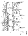
- Fig. 1 shows a rear side of a harvesting device 1 for harvesting crops in a perspective view.
- the harvesting device 1 is designed here as a harvesting attachment and is designed in the manner of a corn header.
- the terms harvesting device 1 and harvesting header are used synonymously.
- the harvesting attachment 1 can be attached to the front of a harvesting machine (not shown) in a manner known per se, for example a forage harvester or a combine harvester, and is guided over a field (not shown) during field operation.
- the harvesting machine has a lifting mechanism that is designed to adjust a height and/or an inclination of the harvesting attachment 1 relative to the field.
- the harvesting attachment 1 can also have one or more detection means, for example sensors, for detecting its height and/or inclination relative to the field.
- the lifting mechanism of the harvesting machine can be controlled based on the detected height and/or inclination.
- the harvesting header 1 comprises several sections 13, 14.
- a left section 13 (in the drawing plane) and a right section 14 (in the drawing plane) are arranged in a field position during field operation in which they are aligned approximately horizontally to the field ground.
- Fig.1 shows the harvesting attachment 1 in the field position intended for field operation.
- the harvesting attachment 1 can be transferred from the field position to a transport position (not shown).
- the left section 13 and the right section 14 are designed to be adjustable relative to one another and to a frame (not shown) of the harvesting attachment 1.
- the harvest header 1 is guided over the field ground in a direction of travel 91, with a cutting and/or conveying device 2 cutting stalk-like crops and feeding them to a feed arrangement (not shown) of the harvesting machine.
- the harvesting attachment 1 has at least one mulching unit 4, which is intended to chop the plant stems remaining in the field soil.
- the mulching unit 4 is arranged downstream of the cutting and/or conveying device 2 in a material flow direction 11.
- the mulching unit 4 processes the plant stems with a processing tool 41 (see. Fig. 2 (b) and (c) ) mechanically after the cutting and/or conveying device 2 has cut the crop, in particular close to the ground.
- the harvesting attachment 1 has a plurality of mulching units 4 which are arranged evenly distributed over a width of the harvesting attachment 1 in a transverse direction 92 which extends transversely to the direction of travel 91.
- a drive train 3 is provided for each of the sections 13, 14, within which the drive shafts 31, 32, 33, 34, 35, 36, 37, 38, 39, 40, 41, 42, 43, 44, 45, 46, 47, 48, 49, 50, 51, 52, 53 14 arranged mulching units 4.
- the drive train 3 comprises a drive shaft 31 in the harvesting attachment 1. It also comprises a gear 7 for each of the mulching units 4.
- it comprises cardan shafts 72 with which the gears 7 of adjacent mulching units 4 are connected to one another in an articulated manner.
- dust and/or splash protection means are arranged around the cardan shafts 72, which are not shown in the left-hand section 13 for clarity.
- the harvesting attachment 1 with the mulching units 4 is driven via a main gearbox 8.
- the main gearbox 8 has a power take-off shaft connection 81 with which it can be connected to the harvesting machine to receive power.
- On the output side it is connected to the two drive shafts 31 of the drive trains 3 for driving the mulching units 4.
- Further drive trains (not shown) can be provided for driving further components of the harvesting attachment 1.
- the harvest header has sensors 6 (see also Fig. 3 ), which are intended to detect an overload occurring on one of the mulching units 4.
- each of the gearboxes 7 provided for driving one of the mulching units 4 has a sensor 6.
- the harvesting machine and/or the harvesting attachment 1 can have a sensor 6' designed as a crop flow sensor for detecting a crop flow in the harvesting attachment 1 and/or in the harvesting machine.
- the sensor 6' is arranged in the harvesting attachment 1. It can be designed as an NIR sensor or as an optoelectric sensor.
- a sensor for detecting a deflection of a feed roller, which is arranged in a feed arrangement of the harvesting machine can also be used as a crop flow sensor.
- a sensor which is arranged in a discharge arch of the harvesting machine and is designed, for example, as an NIR sensor can also be used to detect the crop flow.
- the sensors 6, 6' are connected to a control unit 5, which is designed to pivot the mulching units 4 from a working position S1 into a raised position S2 when the overload is detected and/or when the crop flow is reduced or absent.
- the mulching units 4 each have an actuator 44 for this purpose.
- the mulching units 4 rest on the field ground, in particular with their weight, while in the raised position S2 they are spaced from it.
- a mulching unit 4 or several mulching units 4 are guided at a height above the field floor. This allows uneven ground and/or obstacles to be overcome without overloading the harvesting header 1, the mulching units 4 and/or the drive train 3.
- Fig.1 the mulching units 4 in the left section 13 are all shown in the working position S1, while in the right section 14 one of the mulching units 4 is shown in the raised position S2 relative to the others.
- the pivoting of the mulching unit 4 is explained below using the Fig.2 explained in more detail.
- Fig. 2 (a) shows a section of the right section 14 of the harvesting attachment 1 of the Fig.1 in a perspective view.
- the mulching unit 4 is supported on the field floor by means of a skid 45.
- the mulching unit 4 rests on the field ground with its weight. It is then arranged in the working position S1.
- the mulching unit 4 is pivotally connected to the frame 12 of the harvesting attachment 1 about a pivot axis S. Pivoting the mulching unit 4 about the pivot axis S enables the mulching unit 4 to be lifted from the field ground.
- the pivot axis S extends in a transverse direction 92 transverse to the direction of travel 91. By lifting, the mulching unit 4 is spaced from the field ground in the raised position S2 in a vertical direction 93 that extends transverse to the transverse direction 92 and transverse to the direction of travel 91.
- the mulching unit 4 has the actuator 44 for lifting.
- the actuator 44 extends between the harvesting attachment 1 and the mulching unit 4. This is in Fig. 2 (c) described in more detail.
- the drive of the mulching unit 4, in particular of the processing tool 41 can be provided so that it can be switched off in the raised position S2, in particular automatically.
- the mulching unit 4 has the processing tool 41 for processing the plant stems.
- the processing tool 41 is arranged below a cover 47 of the mulching unit 4 when viewed in the vertical direction 93 (see Fig. 2 (b) and (c) ).
- the cover 47 prevents the machining tool 41 (see Fig. 2 (b) and (c) ) treated plant stems are thrown up.
- the universal joint shaft 72 of the drive train 3 extends between the mulching unit 4 arranged in the raised position S2 and the adjacent mulching unit 4 arranged in the working position S1 at an angle (not designated) to the transverse direction 92.
- the gears 7 of these mulching units 4 are therefore arranged offset from one another in the vertical direction 93. This is possible in that the universal joint shafts 72 between the gears 7 of the mulching units 4 are each connected to gear shafts 76 of the gears 7 by means of cardan joints 78.
- the gears 7 are arranged in series (not designated) one behind the other and are connected to one another by the cardan shafts 72.
- the gears 7 are designed as T-gears and each have the gear shaft 76 (see Fig.3 ) that passes through it.
- the gear shaft 76 of the first gear 7 in the series is connected to the drive shaft 31 of the harvesting attachment 1 or to a spur gear (not designated) connected upstream of the gear 7.
- the gear shafts 76 of the downstream gears 7 are each connected on the drive side to the gear shaft 76 of the adjacent, upstream gear 7 is connected.
- the gear shafts 76 of the gears 7, with the exception of the last gear 7 in the row, are each intended to drive the adjacent, subsequent gear 7.
- the cardan shafts 72 are also linked to the gear shafts 76 of the subsequent gear 7 by means of cardan joints 78. This linkage enables the spatial offset between the gears 7, so that the mulching units 4 can be raised relative to their adjacent mulching units 4.
- Fig. 2 (b) shows a section of the harvest header 1 Fig. 2 (a) in a perspective view in which an underside (not labeled) of the header 1 with several mulching units 4 is visible.
- the drive axles 42 of the processing tools 41 are aligned transversely to the transmission shaft 76 of the transmission 7 (see also Fig. 3 ).
- the machining tool 41 is connected to a tool-side output 71 (see Fig.3 ) of the gear 7 in a rotationally fixed manner, for example screwed, so that the impact body 43 can rotate about the drive axis 42.
- It has a blunt impact body 43 that is intended to work the plant stems in the field soil.
- a plurality of impact bodies 43 are arranged evenly distributed around the drive axis 42.
- An embodiment with two impact bodies 43 is shown here.
- three or more impact bodies 43 can also be used.
- knives can also be provided instead of the impact bodies 43.
- the mulching unit 4 has a mulcher frame 48 and the cover 47.
- the cover 47 is arranged above the processing tool 41. It prevents processed plant stems or disturbed field soil from being thrown upwards by the rotating processing tool 41. This can the cover 47 can be designed as a sheet metal.
- the cover is attached to the mulcher frame 48, which is formed in particular from webs and ribs.
- the gear 7 is arranged on the top side of the mulching unit, on a side of the cover 47 facing away from the processing tool 41. The cover 47 extends in the crop flow direction 11 towards an end to which the skid 45 is attached.
- the skid 45 can be adjusted relative to the cover 47 and/or relative to the processing tool 41 by means of a hole pattern and/or an elongated hole.
- the skid 45 can also be designed to be adjustable by means of an adjustment actuator (not shown), wherein the adjustment actuator is articulated at one end to the mulcher frame 48 and/or the cover 47 of the mulching unit 4 and at another end to the skid 45.
- the cutting and/or conveying device 2 is also shown.
- the cutting and/or conveying device 2 here comprises a plurality of cutting elements 22 and a plurality of conveying elements 23.
- the cutting elements 22 are designed as rotating cutting disks and are arranged evenly distributed over the working width of the harvest header 1.
- a knife bar or the like can also be used instead of these cutting elements 22.
- a continuously driven endless conveyor (not designated) is used to convey the crop.
- Each section 13, 14 of the header 1 has at least one such endless conveyor.
- the conveying elements 23 are arranged on the endless conveyor.
- Each of the conveying elements 23 has a plurality of conveying tines 24, which are intended to carry the crop cut by the cutting element 23.
- a cross conveyor in the form of a screw, rotating conveyor drums or the like can also be used as the conveying element 23.
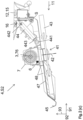
- Fig. 2(c) shows a side view of a sectional view of the mulching unit 4 arranged on the harvesting header 1.
- the linkage of the mulching unit 4 to the frame 12 of the harvesting header 1 can be seen.
- the frame 12 of the harvest header 1 comprises a cross member 15 which extends in the transverse direction 92 and to which a console 16 is screwed.
- the console is therefore detachably attached to the cross member 15 and can be removed by unscrewing it.
- Other fastening means can also be provided with which the console is fastened to the frame 12 of the harvest header 1 in a detachable manner, for example by snapping or clamping, or in a non-detachable manner, for example by gluing, welding or riveting.
- the mulcher frame 48 is mounted on the bracket 16 so that it can pivot about the pivot axis S.
- the pivot axis S can, for example, extend along a pivot shaft (not designated) formed by a pin joint.
- the mulching unit 4 In the working position S1, the mulching unit 4 is suspended so that it swings freely on the pivot axis S, is guided over the field soil by its weight and can therefore follow the contours of the field soil.
- the skid 45 is provided for support on the field soil.
- the actuator 44 for pivoting the mulching unit 4 extends between the harvesting attachment 1, here the bracket 16, and the mulcher frame 48. It is fastened to the bracket 16 and to the mulcher frame 48, for example by means of a bolt 441, 442, in particular about the respective bolt axes (not designated), so as to be rotatable.
- the actuator 44 here is a pneumatic and/or hydraulic cylinder, and in particular is designed to be single-acting. By retracting a piston rod 443 of the actuator 44, the mulching unit 4 is raised relative to the field ground from the working position S1 to the raised position S2.
- the gear 7 is attached to an upper side (not designated) of the cover 47, in particular to the mulcher frame 48 and/or the cover 47. It is Therefore, when the mulching unit 4 is pivoted about the pivot axis S, it is lifted together with the mulching unit.
- the gear shaft 76 of the gear 7 is visible.
- the gear 7 has an output 71 (see Fig. Fig. 3 ), which extends in the direction of the drive axis of the machining tool 41 and can be driven in rotation by the gear shaft 76.
- the machining tool 41 is attached to the output 71 in a rotationally fixed manner and is therefore driven around the drive axle 42 when the transmission 1 is driven.
- the sensor 6 for detecting the overload is arranged in the transmission 7. This will be done as part of the Fig. 3 described.
- the overload occurs when the processing tool 41 hits an obstacle such as a stone or the field soil on the processing tool 41 of the mulching unit 4.
- the processing tool 41 is then braked or blocked.
- the torque acting on the processing tool increases and the speed decreases.
- the sensor 6 By designing the sensor 6 as a speed sensor 61 or as a torque sensor 62, such an impact on the obstacle and the resulting overload can therefore be measured.
- the sensor 6 sends a signal to the control unit 5, which causes the actuator 44 to pivot the mulching unit 4 from the working position S1 into the raised position S2. In the raised position S2, the processing tool 41 is lifted over the obstacle causing the overload and/or lifted out of the field soil.
- the control unit 5 is designed to raise the mulching unit 4 to a preset overload height.
- a height to which the mulching unit 4 is raised in the raised position S2 can also be set depending on an amount of overload.
- the control unit 5 is further configured to move the mulching unit 4 in a time-controlled and/or distance-controlled manner from the raised position S2 to the Working position S1 to be swung back.
- the time control and/or the path control when the mulching unit 4 is swung back from the raised position S2 to the working position S1 can be carried out with preset or presettable amounts for the time and/or the path, or depending on the amount of the overload.
- mulching units 4 can also be assigned to a group.
- the control unit 5 pivots all mulching units 4 of the group from the working position S1 into the raised position S2 when the overload on one of the mulching units 4 of the group is detected.
- the mulching units 4 of one of the sections 13, 14 of the front harvesting attachment 1 and/or those mulching units 4 that are connected to the same drive train 3 can be assigned to a group and pivoted together from the working position S1 into the raised position S2.
- Fig. 3 shows in (a) and (b) various embodiments of a transmission 7 for such a mulching unit 4.
- the gears 7 are each designed as T-gears. They each have a housing 77 through which the gear shaft 76 passes.
- the gear shafts have open ends 761, 762 opposite one another.
- the open ends 761, 762 can each be connected, in particular by means of the universal joints 78 and universal shafts 72, on the drive side to the drive shaft 31 of the front harvesting attachment 1 or to the gear 7 of the mulching unit 4 arranged upstream of them, and on the output side to the gear 7 of the mulching unit 4 arranged downstream of them.
- Each of the gears 7 includes a pair of bevel gears 74, 75 with a first bevel gear 74, which completely surrounds the gear shaft 76, and a second bevel gear 75, which forms an output 71 on the tool side.
- the two bevel gears 74, 75 each have teeth (not designated) which engage with one another, so that the second bevel gear 75 is driven when the first bevel gear 74 is driven.
- the processing tool 41 is on, in particular at a fastening point 49 the tool-side output 71 is mounted. As a result, the machining tool 41 is also driven when the first bevel gear 74 is driven.
- the drive axle 42 (see Fig. 2 (c) ) of the machining tool 41 is aligned transversely to the transmission shaft 76.
- the transmission 7 has an overload clutch 73, which is designed here as a ratchet clutch, for example.
- the overload clutch 73 is intended to drive-disconnect the drive train 3 from the tool-side output 71 of the mulching unit 4 when an overload occurs on the mulching unit 4.
- it has engagement means (not shown) which, in an engaged state (not designated) of the overload clutch 73, are spring-loaded into engagement with counter-engagement means (not shown) of the transmission shaft 76, in particular with recesses in the transmission shaft 76, and which, when an engagement force is exceeded, come out of engagement with the counter-engagement means, so that the overload clutch 73 is uncoupled from the transmission shaft 76.
- the overload clutch 73 then slips on the transmission shaft 76.
- the first bevel gear 74 is mounted on the overload clutch 73 in a rotationally fixed manner. When the overload clutch 73 is engaged, it therefore rotates with the transmission shaft 76. When the overload occurs on the machining tool 41, it is braked or even blocked, so that the second bevel gear 75 is braked. As a result, the first bevel gear 74 is also braked. Depending on the force acting on the first bevel gear 74, that is to say when the engagement force is exceeded, the overload clutch 73 slips, so that the machining tool 41 is operationally separated from the transmission shaft 76, and thus the drive train 3. This protects the drive train 3 from damage if the processing tool 41 is overloaded.
- the sensor 6 is designed as a speed sensor 61.
- the speed sensor 61 is mounted in the housing 77 and detects a speed of the first bevel gear 74. Since the two bevel gears 74, 75 are in mesh with each other, the speed of the tool-side output 71 is also measured. The occurrence of the overload is detected when the speed of the tool-side output 71 falls below a threshold value.
- the occurrence of the overload can alternatively be detected when a speed difference between a highest of the currently detected speeds of the mulching units 4 of the group and a lowest of the currently detected speeds of the mulching units 4 of the group falls below a threshold value.
- the speed sensor 61 or the speed sensors 61 send their measured value to the control unit 5, which carries out the threshold value comparison and, when an overload is detected, pivots the mulching unit 4 or the mulching units 4 of the group from the working position S1 to the raised position S2.
- Fig. 3 (b) shows an embodiment of the transmission 7 in which the sensor 6 for detecting the overload is designed as a torque sensor 62.
- the torque sensor 62 is designed here in the form of a torque measuring hub 62. Therefore, the terms torque sensor 62 and torque measuring hub 62 are used synonymously below.
- the two bevel gears 74, 75 each have a toothing (not designated) that mesh with one another, so that the second bevel gear 75 is driven when the first bevel gear 74 is driven.
- no overload clutch 73 is visible here.
- the gear 7 preferably has the overload clutch 73 here too in order to separate the tool-side output 71 from the drive train 3.
- the overload clutch can be integrated into the torque measuring hub 62, for example.
- the torque sensor 62 detects the torque applied to the first bevel gear 74. Since the first and second bevel gears 74, 75 are in engagement with one another, the torque applied to the machining tool 41 is thereby detected. The occurrence of the overload is detected by a threshold value comparison, namely when the torque exceeds a threshold value.
- the overload can also be detected alternatively in the case of grouped mulching units 4 if a torque difference between a highest of the currently detected torques of the mulching units 4 of the group and a lowest of the currently detected torques of the mulching units 4 of the group exceeds a threshold value.
- the torque sensor 61 or the torque sensors 61 send their measured value to the control unit 5, which carries out the threshold value comparison and, if an overload is detected, pivots the mulching unit 4 or the mulching units 4 of the group from the working position S1 to the raised position S2.
- the mulching unit 4 or mulching units 4 are pivoted back from the raised position S2 into the working position S1 automatically, in particular time-controlled and / or distance-controlled. It is also conceivable for the mulching unit 4 or mulching units 4 to be automatically lowered depending on the speed or torque on the processing tool 41 or on the processing tools 41.
- the currently recorded measured values, in particular speed or torque, of the sensor 6 and/or the occurrence of the overload can be displayed to the operator on an operator console, for example in a driver's cab of the harvester 1. If an overload occurs, an acoustic signal can alternatively or additionally be issued to the driver.
- navigation data in particular from a GPS receiver (not shown) of the harvesting machine 1, can be stored in order to be able to subsequently process the field soil in a targeted manner.
Abstract
Die vorliegende Erfindung betrifft eine Erntemaschine mit einem Erntegerät (1), an dem wenigstens eine Mulcheinheit (4) angeordnet ist, wobei• das Erntegerät (1) eine Schneid- (2) und/oder Fördereinrichtung (3) zum Ernten von stängelartigem Erntegut aufweist, und• die Mulcheinheit (4) ein um eine Antriebsachse (42) rotierend antreibbares Bearbeitungswerkzeug (41) zum Bearbeiten von bei der Ernte in einem Feldboden verbleibenden Pflanzenstängeln aufweist, der Schneid- (2) und/oder Fördereinrichtung (3) in einer Gutflussrichtung (11) nachgeordnet ist, sich in einem Feldbetrieb in einer Arbeitsstellung (S1) auf dem Feldboden abstützt, und um eine Schwenkachse (S) an einem Rahmen (12) des Erntegerätes (1) relativ zu diesem schwenkbar gelagert ist, wobei die Erntemaschine eine Steuerungseinheit (5) und wenigstens einen Sensor (6, 6') umfasst, wobei der Sensor (6) zur Erfassung einer auf das Bearbeitungswerkzeug (41) wirkenden Überlast vorgesehen ist, und die Steuerungseinheit (5) dazu eingerichtet ist, die Mulcheinheit (4) bei Erfassen der Überlast relativ zur Arbeitsstellung (S1) in eine angehobene Stellung (S2) zu verschwenken, und/oderder Sensor (6') zur Erfassung eines Gutflusses in der Erntemaschine vorgesehen ist, und die Steuerungseinheit (5) dazu eingerichtet ist, die Mulcheinheit (4) bei Erfassung eines verringerten oder ausbleibenden Gutflusses relativ zur Arbeitsstellung (S1) in die angehobene Stellung (S2) zu verschwenken.The present invention relates to a harvesting machine with a harvesting device (1) on which at least one mulching unit (4) is arranged, wherein • the harvesting device (1) has a cutting (2) and/or conveying device (3) for harvesting stalk-like crops, and • the mulching unit (4) has a processing tool (41) that can be driven in rotation about a drive axis (42) for processing plant stems that remain in a field soil during harvesting, which is arranged downstream of the cutting (2) and/or conveying device (3) in a crop flow direction (11), is supported on the field soil in a working position (S1) during field operation, and is pivotably mounted about a pivot axis (S) on a frame (12) of the harvesting device (1) relative to the latter, wherein the harvesting machine comprises a control unit (5) and at least one sensor (6, 6'), wherein the sensor (6) is provided for detecting an overload acting on the processing tool (41), and the control unit (5) is designed to pivot the mulching unit (4) into a raised position (S2) relative to the working position (S1) when the overload is detected, and/orthe sensor (6') is provided for detecting a crop flow in the harvesting machine, and the control unit (5) is designed to pivot the mulching unit (4) into the raised position (S2) relative to the working position (S1) when a reduced or lacking crop flow is detected.
Description
Die vorliegende Erfindung betrifft eine Erntemaschine mit einem Erntegerät, an dem wenigstens eine Mulcheinheit angeordnet ist, wobei
- das Erntegerät eine Schneid- und/oder Fördereinrichtung zum Ernten von stängelartigem Erntegut aufweist, und
- die Mulcheinheit ein um eine Antriebsachse rotierend antreibbares Bearbeitungswerkzeug zum Bearbeiten von bei der Ernte in einem Feldboden verbleibenden Pflanzenstängeln aufweist, der Schneid- und/oder Fördereinrichtung in einer Gutflussrichtung nachgeordnet ist, sich in einem Feldbetrieb in einer Arbeitsstellung auf dem Feldboden abstützt, und um eine Schwenkachse an einem Rahmen des Erntegerätes relativ zu diesem schwenkbar gelagert ist,
- the harvesting device has a cutting and/or conveying device for harvesting stalk-like crops, and
- the mulching unit has a processing tool that can be driven in rotation about a drive axis for processing plant stems remaining in a field soil during harvesting, is arranged downstream of the cutting and/or conveying device in a crop flow direction, is supported in a working position on the field soil in a field operation, and a The pivot axis is mounted on a frame of the harvesting device so that it can pivot relative to the latter,
Bei der Ernte von stängeligem Erntegut wie beispielsweise Mais oder Sonnenblumen werden oftmals Mulchgeräte eingesetzt, um die im Boden verbleibenden Pflanzenstängel zu zerkleinern. Das Zerkleinern fördert die Verrottung. Weiterhin lassen sich die zerkleinerten Pflanzenstängel bei einer anschließenden Bodenbearbeitung besser einmischen. Zudem kann so einem Schädlingsbefall, beispielsweise durch Maiszünsler, vorgebeugt werden.When harvesting stalky crops such as corn or sunflowers, mulching devices are often used to shred the plant stems that remain in the ground. Crushing promotes rotting. Furthermore, the shredded plant stems can be better mixed in during subsequent soil cultivation. In addition, pest infestation, such as corn borers, can be prevented.
Solche Mulchgeräte sind regelmäßig an einem Erntegerät, insbesondere einem Erntevorsatzgerät, angeordnet und einem zum Ernten des Erntegutes vorgesehenen Schneidwerkzeug des Erntegerätes in einer Gutflussrichtung nachgeordnet. Sie sind bodennah angeordnet und kommen daher immer wieder mit Hindernissen wie beispielsweise Steinen oder Bodenunebenheiten in Kontakt. Durch das Auftreffen auf solche Hindernisse werden nicht nur jeweils das Bearbeitungswerkzeug der Mulchgeräte, sondern auch ihr Antriebsstrang, insbesondere Getriebe und/oder Kupplungen des Antriebsstrangs, belastet, so dass Beschädigungen auftreten können oder zumindest Verschleiß auftritt.Such mulching devices are regularly arranged on a harvesting device, in particular a harvesting header, and are arranged downstream of a cutting tool of the harvesting device provided for harvesting the crop in a crop flow direction. They are arranged close to the ground and therefore repeatedly come into contact with obstacles such as stones or uneven ground. By hitting Such obstacles not only put a strain on the processing tool of the mulching devices, but also on their drive train, in particular the gearbox and/or clutches of the drive train, so that damage can occur or at least wear and tear occurs.
Um bei einem ungünstigen Auftreffen eines Bearbeitungswerkzeugs eines Mulchgerätes auf ein Hindernis wie einen Stein erhebliche Beschädigungen im Antriebsstrang des Mulchgerätes zu verhindern, offenbart die Druckschrift
Solche Hindernisse treten im Vorgewende vermehrt auf. Zudem kann ein Mulchgerät aufgrund seiner bodennahen Anordnung bei Rückwärtsfahrt in den Feldboden eindringen.Such obstacles occur more frequently in headlands. In addition, due to its location close to the ground, a mulcher can penetrate the field soil when reversing.
Die Druckschrift
Aufgabe der vorliegenden Erfindung ist es, eine Erntemaschine mit einem Erntegerät, an dem eine Mulcheinheit angeordnet ist, zu schaffen, bei dem ein Verschleiß an der Mulcheinheit, dem Antriebsstrang der Mulcheinheit und/oder dem Erntegerät verringert und/oder eine Standzeit der Mulcheinheit, des Antriebsstrangs und/oder des Erntegerätes erhöht ist, und die für den Fahrer leicht handhabbar ist, wobei die Mulcheinheit kostengünstig herstellbar und/oder betreibbar ist.The object of the present invention is to create a harvesting machine with a harvesting device on which a mulching unit is arranged, in which wear on the mulching unit, the drive train of the mulching unit and / or the harvesting device is reduced and / or a service life of the mulching unit drivetrain and/or the harvesting device is increased, and which is easy to handle for the driver, the mulching unit being inexpensive to produce and/or operate.
Die Aufgabe wird gelöst mit einer Erntemaschine mit den Merkmalen des unabhängigen Patentanspruchs 1, einem Erntegerät mit den Merkmalen des unabhängigen Patentanspruchs 15, einer Mulcheinheit mit den Merkmalen des unabhängigen Patentanspruchs 16 sowie einem Verfahren mit den Merkmalen des unabhängigen Patentanspruchs 17. Vorteilhafte Ausführungsformen sind den abhängigen Ansprüchen entnehmbar.The object is achieved with a harvesting machine having the features of
Dafür wird eine Erntemaschine mit einem Erntegerät geschaffen, wobei am Erntegerät wenigstens eine Mulcheinheit angeordnet ist, wobei
- das Erntegerät eine Schneid- und/oder Fördereinrichtung zum Ernten von stängelartigem Erntegut aufweist, und
- die Mulcheinheit ein um eine Antriebsachse rotierend antreibbares Bearbeitungswerkzeug zum Bearbeiten von bei der Ernte in einem Feldboden verbleibenden Pflanzenstängeln aufweist, der Schneid- und/oder Fördereinrichtung in einer Gutflussrichtung nachgeordnet ist, sich in einem Feldbetrieb in einer Arbeitsstellung auf dem Feldboden abstützt, und um eine Schwenkachse an einem Rahmen des Erntegerätes relativ zu diesem schwenkbar gelagert ist,
- the harvesting device has a cutting and/or conveying device for harvesting stalk-like crops, and
- the mulching unit has a processing tool that can be driven in rotation about a drive axis for processing plant stems remaining in a field soil during harvesting, is arranged downstream of the cutting and/or conveying device in a material flow direction, is supported on the field soil in a working position during field operation, and is mounted pivotably about a pivot axis on a frame of the harvesting device relative to the latter,
Die Erntemaschine zeichnet sich dadurch aus, dass der Sensor zur Erfassung einer auf das Bearbeitungswerkzeug wirkenden Überlast vorgesehen ist, und die Steuerungseinheit dazu eingerichtet ist, die Mulcheinheit bei Erfassen der Überlast relativ zur Arbeitsstellung in eine angehobene Stellung zu verschwenken, und/oder der Sensor zur Erfassung eines Gutflusses in der Erntemaschine vorgesehen ist, und die Steuerungseinheit dazu eingerichtet ist, die Mulcheinheit bei verringertem oder ausbleibendem Gutfluss relativ zur Arbeitsstellung in die angehobene Stellung zu verschwenken.The harvesting machine is characterized in that the sensor is provided for detecting an overload acting on the processing tool, and the control unit is configured to pivot the mulching unit into a raised position relative to the working position when the overload is detected, and/or the sensor is provided for detecting a crop flow in the harvesting machine, and the control unit is configured to pivot the mulching unit into the raised position relative to the working position when the crop flow is reduced or absent.
Durch das Anheben der Mulcheinheit bei Erfassung der Überlast kann das Bearbeitungswerkzeug der Mulcheinheit bei Kontakt mit einem Hindernis, wie beispielsweise einem Stein oder einer Bodenunebenheit, über das Hindernis hinweggehoben werden. Dadurch wird es automatisch aus dem Blockadebereich gehoben. Da die Mulcheinheit automatisch aus dem Blockadebereich gehoben wird, wird die Überlast sehr schnell behoben und das Erntegerät nur sehr kurzzeitig belastet. Außerdem muss der Fahrer dabei nicht eingreifen, kann seine Aufmerksamkeit auf den weiteren Erntevorgang richten und wird durch die Beobachtung der Mulcheinheit nicht beansprucht oder abgelenkt.By raising the mulching unit when the overload is detected, the processing tool of the mulching unit can be lifted over the obstacle when it comes into contact with an obstacle, such as a stone or an uneven ground. This will automatically lift it out of the blockage area. Since the mulching unit is automatically lifted out of the blockage area, the overload is eliminated very quickly and the harvesting device is only loaded for a very short time. In addition, the driver does not have to intervene, can focus his attention on the further harvesting process and is not stressed or distracted by watching the mulching unit.
Sofern das Bearbeitungswerkzeug bereits in den Feldboden eingedrungen ist, wird es sehr schnell aus diesem herausgehoben. Dadurch tritt am Bearbeitungswerkzeug nur sehr kurzzeitig Verschleiß auf, der Verschleiß ist somit gering, und die Standzeit des Bearbeitungswerkzeugs hoch. Außerdem tritt durch die Überlast kein Wartungsaufwand auf dem Feld auf, da die Mulcheinheit nach Auftreten der Überlast weiter betrieben werden kann.If the processing tool has already penetrated the field soil, it will be lifted out of it very quickly. As a result, wear on the machining tool only occurs for a very short time, the wear is therefore low and the service life of the machining tool is long. In addition, the overload does not require any maintenance work in the field, as the mulching unit can continue to operate after the overload occurs.
Durch die Erfassung eines sich verringernden oder ausbleibenden Gutflusses wird erreicht, dass die Mulcheinheit im Feldbetrieb nur so lange in die Arbeitsstellung verschwenkt ist, wie Erntegut geerntet wird. Wenn kein Erntegut geerntet wird, wird die Mulcheinheit relativ zur Arbeitsstellung in die angehobene Stellung verschwenkt, beispielsweise bei Stillstand der Erntemaschine oder bei Wendemanövern, insbesondere im Vorgewende und/oder bei Rückwärtsfahrt. Da die Mulcheinheit bei sich verringernden oder ausbleibenden Gutfluss von der Arbeitsstellung in die angehobene Stellung verschwenkt ist, wird ein unnötiger Betrieb der Mulcheinheit vermieden, so dass erst gar keine Überlast am Bearbeitungswerkzeug auftreten kann. Dabei kann weiterhin vorgesehen sein, dass das Bearbeitungswerkzeug in der angehobenen Stellung der Mulcheinheit nicht betrieben wird. Dadurch ist der Leistungsbedarf der Erntemaschine verringert.By detecting a decreasing or lacking crop flow, the mulching unit is only pivoted into the working position during field operation as long as crops are being harvested. When no crops are being harvested, the mulching unit is pivoted into the raised position relative to the working position, for example when the harvester is at a standstill or during turning maneuvers, particularly on headlands and/or when reversing. Since the mulching unit is pivoted from the working position into the raised position when the crop flow decreases or fails, unnecessary operation of the mulching unit is avoided, so that no overload can occur on the processing tool. It can also be provided that the processing tool is not operated when the mulching unit is in the raised position. This reduces the power requirement of the harvester.
Da im Vorgewende und/oder bei Rückwärtsfahrt vermehrt mit einem Auftreffen des Bearbeitungswerkzeugs auf ein Hindernis wie beispielsweise auf einen Stein oder eine Bodenunebenheit zu rechnen ist, führt auch das Anheben in Abhängigkeit vom Gutfluss zu einem verringerten Verschleiß und einer erhöhten Standzeit des Bearbeitungswerkzeugs und/oder des Antriebsstrangs. Durch die verlängerte Standzeit sind zudem wenigstens langfristig oder sogar mittelfristig die (Wartungs-) Kosten für die Mulcheinheit verringert.Since the working tool is more likely to hit an obstacle such as a stone or an uneven ground when turning at the headland and/or reversing, lifting the machine, depending on the Crop flow leads to reduced wear and an increased service life of the processing tool and/or the drive train. The extended service life also reduces the (maintenance) costs for the mulching unit, at least in the long term or even in the medium term.
Das Erntegerät ist in einer bevorzugten Ausführungsform ein Erntevorsatzgerät für eine, insbesondere selbstfahrende, Erntemaschine. Als solches ist es vorzugsweise frontseitig der Erntemaschine angeordnet. Die Mulcheinheit ist aber auch für andere Erntegeräte verwendbar, die beispielsweise an einen Schlepper anhängbar oder heckseitig anbaubar sind.In a preferred embodiment, the harvesting device is a harvesting attachment for a harvesting machine, in particular a self-propelled one. As such, it is preferably arranged at the front of the harvester. The mulching unit can also be used for other harvesting devices that can be attached to a tractor or mounted on the rear, for example.
In einer bevorzugten Ausführungsform ist der Sensor zur Erfassung der Überlast vorgesehen, und als Drehzahlsensor oder als Drehmomentsensor ausgebildet, der an der Mulcheinheit angeordnet ist. Die Überlast kann dann unmittelbar an der Mulcheinheit, insbesondere am oder nahe dem Bearbeitungswerkzeug, erfasst werden. Aufgrund der Vielzahl eingesetzter Drehzahlsensoren und Drehmomentsensoren in technischen Vorrichtungen sind solche Sensoren sehr kostengünstig erhältlich und die Erfassung der Überlast in der Mulcheinheit ist daher sehr kostengünstig realisierbar.In a preferred embodiment, the sensor is provided for detecting the overload and is designed as a speed sensor or as a torque sensor which is arranged on the mulching unit. The overload can then be detected directly on the mulching unit, in particular on or near the processing tool. Due to the large number of speed sensors and torque sensors used in technical devices, such sensors are available very inexpensively and the detection of the overload in the mulching unit can therefore be implemented very cost-effectively.
Dabei ist es bevorzugt, dass die Mulcheinheit ein Getriebe umfasst, das eingangsseitig an einen Antriebsstrang des Erntegerätes und/oder der Erntemaschine angeschlossen ist, und das einen werkzeugseitigen Abtrieb zum Antrieb des Bearbeitungswerkzeugs umfasst, wobei der Sensor im Getriebe angeordnet ist. Durch die Anordnung des Sensors im Getriebe ist der Sensor nahe dem Bearbeitungswerkzeug angeordnet. In einer bevorzugten Ausführungsform wird als Sensor ein ohnehin für die Erfassung der Antriebsdrehzahl des Getriebes oder der Mulcheinheit vorgesehener Sensor genutzt. Dadurch fallen keine Kosten für einen zusätzlichen Sensor an.It is preferred that the mulching unit comprises a transmission which is connected on the input side to a drive train of the harvesting device and/or the harvesting machine, and which comprises a tool-side output for driving the processing tool, the sensor being arranged in the transmission. Due to the arrangement of the sensor in the gearbox, the sensor is arranged close to the processing tool. In a preferred embodiment, a sensor that is already provided for detecting the drive speed of the transmission or the mulching unit is used as the sensor. This means there are no costs for an additional sensor.
Dabei ist es weiterhin bevorzugt, dass der Sensor zum Erfassen der Überlast
- am werkzeugseitigen Abtrieb des Getriebes eine Drehzahl des Bearbeitungswerkzeugs erfasst, oder
- als Drehmomentmessnabe ausgebildet ist und antriebsseitig des Getriebes oder am werkzeugseitigen Abtrieb des Getriebes ein Drehmoment erfasst.
- a speed of the machining tool is recorded at the tool-side output of the gearbox, or
- is designed as a torque measuring hub and measures a torque on the drive side of the gearbox or on the tool-side output of the gearbox.
Vorzugsweise weist die Erntemaschine eine Vielzahl Mulcheinheiten auf, wobei für jede der Mulcheinheiten jeweils ein Getriebe vorgesehen ist, wobei jede der Mulcheinheiten einen Sensor zum Erfassen der Überlast umfasst. Dadurch kann in jeder Mulcheinheit jeweils eine auftretende Überlast separat erfasst werden.The harvesting machine preferably has a plurality of mulching units, with a gearbox being provided for each of the mulching units, with each of the mulching units comprising a sensor for detecting the overload. This means that any overload that occurs can be recorded separately in each mulching unit.
In einer bevorzugten Ausführungsform sind die Getriebe von zwei oder mehr der Mulcheinheiten mittels Gelenkwellen miteinander verbunden. Dadurch sind sie in einer Reihe hintereinander angeordnet. Dafür weisen die Getriebe der Mulcheinheiten bevorzugt jeweils einen Abtrieb zum Antrieb eines benachbarten Getriebes einer benachbarten Mulcheinheit auf. In einer besonders bevorzugten Ausführungsform sind die Getriebe jeweils als T- Getriebe ausgebildet. Dafür weisen sie bevorzugt jeweils eine sie durchsetzende, einenends antreibbare Getriebewelle auf, die anderenends zum Antrieb des benachbarten Getriebes genutzt wird. Die Getriebewelle ist an ihren Enden bevorzugt jeweils mittels eines Kardangelenks an die Gelenkwellen angebunden, um einen räumlichen Versatz zwischen den Getrieben zu ermöglichen. Dadurch kann eine Mulcheinheit relativ zu ihrer benachbarten Mulcheinheit oder ihren benachbarten Mulcheinheiten räumlich versetzt angeordnet werden, insbesondere höhenversetzt. Die Gelenkwellen ermöglichen daher, dass jede der Mulcheinheiten jeweils unabhängig von einer benachbarten Mulcheinheit anhebbar und/oder absenkbar ist.In a preferred embodiment, the transmissions of two or more of the mulching units are connected to one another by means of cardan shafts. This means they are arranged in a row one behind the other. For this purpose, the gearboxes of the mulching units preferably each have an output for driving an adjacent gearbox of an adjacent mulching unit. In a particularly preferred embodiment, the gears are each designed as a T-gear. For this purpose, they each preferably have a transmission shaft passing through them, which can be driven at one end and which is used at the other end to drive the adjacent transmission. The ends of the transmission shaft are preferably connected to the cardan shafts by means of a cardan joint in order to enable a spatial offset between the transmissions. As a result, a mulching unit can be arranged spatially offset relative to its adjacent mulching unit or units, in particular offset in height. The cardan shafts therefore enable each of the mulching units to be raised and/or lowered independently of an adjacent mulching unit.
Das Erntegerät kann zum Antrieb der Mulcheinheiten einen oder mehrere Antriebsstränge aufweisen. In einer bevorzugten Ausführungsform bilden jeweils mindestens zwei Mulcheinheiten, die an denselben Antriebsstrang angeschlossen und miteinander verbunden sind, eine Gruppe. Durch eine solche Gruppierung der Mulcheinheiten können die Mulcheinheiten derselben Gruppe, insbesondere in Bezug auf das Drehmoment und/oder die Drehzahl ihrer Bearbeitungswerkzeuge, gemeinsam überwacht werden. Da die Mulcheinheiten der Gruppe trieblich miteinander verbunden sind, kann selbst bei einem Ausfall des Sensors einer der Mulcheinheiten eine Überlasterkennung durch die trieblich verbundenen weiteren, insbesondere benachbarten, Mulcheinheiten erfolgen. Dadurch ist quasi eine redundante Überlasterkennung möglich. Anhand einer solchen Überwachung kann auch ein Ausfall oder eine Fehlfunktion einer Mulcheinheit der Gruppe oder eines der Sensoren der Mulcheinheiten erfasst werden.The harvesting device can have one or more drive trains to drive the mulching units. In a preferred embodiment, at least two mulching units that are connected to the same drive train and interconnected form a group. By grouping the mulching units in this way, the mulching units of the same group, in particular in In relation to the torque and/or the speed of their processing tools, they are monitored together. Since the mulching units in the group are connected to one another by drive, even if the sensor in one of the mulching units fails, overload detection can be carried out by the other, particularly neighboring, mulching units that are connected by drive. This essentially enables redundant overload detection. This type of monitoring can also detect a failure or malfunction of a mulching unit in the group or one of the sensors in the mulching units.
Bei Auftreten der Überlast an einer oder an mehreren Mulcheinheiten können die Mulcheinheiten, insbesondere in Abhängigkeit von der zur Verfügung stehenden hydraulischen Leistung, separat, oder können die Mulcheinheiten einer Gruppe gemeinsam von der Arbeitsstellung in die angehobene Stellung angehoben werden.If the overload occurs on one or more mulching units, the mulching units can be raised separately, in particular depending on the hydraulic power available, or the mulching units of a group can be raised together from the working position to the raised position.
Alternativ kann für die Überwachung der Überlast der Mulcheinheiten einer solchen Gruppe nur ein Sensor vorgesehen sein, wobei die Mulcheinheiten bei Auftreten der Überlast gemeinsam von der Arbeitsstellung in die angehobene Stellung verschwenkt werden.Alternatively, only one sensor can be provided to monitor the overload of the mulching units of such a group, with the mulching units being pivoted together from the working position to the raised position when the overload occurs.
Das Erntegerät der Erntemaschine umfasst bevorzugt wenigstens zwei Abschnitte, wobei jedem der Abschnitte mindestens zwei Mulcheinheiten, vorzugsweise mehr, insbesondere derselben Gruppe, zugeordnet sind. Vorzugsweise sind die Mulcheinheiten der Abschnitte jeweils über eine Breite der Abschnitte gleichmäßig verteilt angeordnet. Die Abschnitte des Erntegerätes können zueinander verstellbar vorgesehen sein, so dass sie beispielsweise durch eine Verstellmechanik reversibel von einer Arbeitsposition in eine Transportposition verbringbar sind. In dieser Ausführungsform ist es besonders bevorzugt, dass für jeden der Abschnitte des Erntegerätes jeweils wenigstens ein Antriebsstrang zum Antrieb der Mulcheinheiten vorgesehen ist. Besonders bevorzugt bilden die Mulcheinheiten jedes Abschnitts außerdem eine Gruppe. Das Erntegerät weist zudem vorzugsweise ein Hauptgetriebe auf, das die Antriebsstränge leistungsempfangend mit einer Zapfwelle der Erntemaschine verbindet.The harvesting device of the harvesting machine preferably comprises at least two sections, with each of the sections being assigned at least two mulching units, preferably more, in particular of the same group. The mulching units of the sections are preferably arranged evenly distributed over a width of the sections. The sections of the harvesting device can be provided so that they can be adjusted relative to one another, so that they can be reversibly moved from a working position to a transport position, for example by an adjustment mechanism. In this embodiment, it is particularly preferred that at least one drive train is provided for each of the sections of the harvesting device to drive the mulching units. The mulching units of each section also particularly preferably form a group. The harvesting device also preferably has a main transmission which connects the drive trains to a power take-off shaft of the harvesting machine in a way that receives power.
Dabei ist es bevorzugt, dass die Steuerungseinheit dazu eingerichtet ist, bei Auftreten der Überlast an einer Mulcheinheit diese Mulcheinheit separat oder gemeinsam die Mulcheinheiten des Abschnittes, in dem sie angeordnet ist, oder gemeinsam die Mulcheinheiten der Gruppe, zu der sie gehört, von der Arbeitsstellung in die angehobene Stellung zu verschwenken.It is preferred that the control unit is set up to, when an overload occurs on a mulching unit, this mulching unit separately or together the mulching units of the section in which it is arranged, or together the mulching units of the group to which it belongs, from the working position to pivot into the raised position.
In einer weiteren bevorzugten Ausführungsform weist das Getriebe eine Überlastkupplung auf, die dazu eingerichtet ist, den werkzeugseitigen Abtrieb des Getriebes vom übrigen Antriebsstrang trieblich zu trennen. Dadurch wird das Bearbeitungswerkzeug bei Auftreten der Überlast an der Überlastkupplung trieblich auch von allen anderen Antriebssträngen des Erntegerätes und/oder der Erntemaschine getrennt. Die Überlastkupplung dient daher nicht nur dem Schutz der überlasteten Mulcheinheit. Sondern gleichzeitig werden auch alle anderen trieblich mit ihr verbundenen Antriebsstränge und/oder Getriebe des Erntegerätes und/oder der Erntemaschine durch sie geschützt. Dadurch treten am Bearbeitungswerkzeug der Mulcheinheit und/oder am Erntegerät im Vergleich zu herkömmlichen Mulcheinheiten weniger häufig Beschädigungen auf. Dabei tritt durch die Überlast Verschleiß an der Überlastkupplung auf. Die Überlastkupplung kann aber so ausgelegt sein, dass der Verschleiß durch Anheben der Mulcheinheit nur sehr gering ist.In a further preferred embodiment, the transmission has an overload clutch which is designed to drive-separate the tool-side output of the transmission from the rest of the drive train. As a result, when an overload occurs on the overload clutch, the processing tool is also drive-separated from all other drive trains of the harvesting device and/or the harvesting machine. The overload clutch therefore not only serves to protect the overloaded mulching unit. At the same time, it also protects all other drive trains and/or transmissions of the harvesting device and/or the harvesting machine that are connected to it. As a result, the processing tool of the mulching unit and/or the harvesting device is less likely to be damaged than with conventional mulching units. The overload causes wear on the overload clutch. However, the overload clutch can be designed in such a way that the wear caused by lifting the mulching unit is very minimal.
Bei Nutzung einer drehmomenterhaltenden Überlastkupplung kann der Anlauf des Bearbeitungswerkzeugs nach Überwinden der Überlast oder Blockade automatisch erfolgen. Auch dadurch wird der Fahrer bei einer an einer der Mulcheinheiten auftretenden Überlast nicht durch diese belastet.When using a torque-maintaining overload clutch, the processing tool can start up automatically once the overload or blockage has been overcome. This also means that the driver is not burdened by an overload that occurs on one of the mulching units.
Eine zuverlässige Erfassung der Überlast kann anhand einer Vielzahl von Berechnungen erfolgen. Vorzugsweise wird die Überlast anhand eines Schwellwertvergleiches erfasst. Die Steuerungseinheit ist bevorzugt dazu eingerichtet, die Überlast zu erfassen, wenn
- a) die aktuell erfasste Drehzahl des Bearbeitungswerkzeugs, oder
- b) eine Drehzahldifferenz zwischen einer höchsten der aktuell erfassten Drehzahlen von mindestens zwei Mulcheinheiten, insbesondere derselben Gruppe, und einer niedrigsten der aktuell erfassten Drehzahlen der mindestens zwei Mulcheinheiten, einen Schwellwert unterschreitet, und/oder wenn
- c) das aktuell erfasste Drehmoment des Bearbeitungswerkzeugs, oder
- d) eine Drehmomentdifferenz zwischen einem höchsten der aktuell erfassten Drehmomente von mindestens zwei Mulcheinheiten, insbesondere derselben Gruppe, und einem niedrigsten der aktuell erfassten Drehmomente der mindestens zwei Mulcheinheiten,
einen Schwellwert überschreitet, und/oder wenn - e) eine Differenz aus einer Antriebsdrehzahl des Erntegerätes oder der Erntemaschine und der aktuell erfassten Drehzahl des Bearbeitungswerkzeugs einen Schwellwert unterschreitet, oder
- f) eine Differenz aus einem Antriebsdrehmoment des Erntegerätes oder der Erntemaschine und dem Drehmoment des Bearbeitungswerkzeugs einen Schwellwert überschreitet.
- a) the currently recorded speed of the machining tool, or
- b) a speed difference between a highest of the currently recorded speeds of at least two mulching units, in particular of the same group, and a lowest of the currently recorded speeds of the at least two mulching units falls below a threshold value, and/or if
- c) the currently measured torque of the machining tool, or
- d) a torque difference between a highest of the currently recorded torques of at least two mulching units, in particular of the same group, and a lowest of the currently recorded torques of the at least two mulching units,
exceeds a threshold, and/or if - e) a difference between a drive speed of the harvesting device or harvesting machine and the currently recorded speed of the processing tool falls below a threshold value, or
- f) a difference between a drive torque of the harvesting device or harvesting machine and the torque of the processing tool exceeds a threshold value.
Alternativ oder zusätzlich kann die Steuerungseinheit auch dazu eingerichtet sein, die Überlast zu erfassen, wenn
- g) eine Durchschnittsdrehzahl aus den aktuell erfassten Drehzahlen von mindestens zwei Mulcheinheiten, insbesondere derselben Gruppe, oder
- h) eine Durchschnittsdrehzahl oder eine Drehzahldifferenz aus mindestens zwei zeitlich aufeinanderfolgenden Drehzahlen derselben Mulcheinheit, oder
- i) eine Durchschnittsdrehzahl aus jeweils mindestens zwei zeitlich aufeinanderfolgenden Drehzahlen von mindestens zwei Mulcheinheiten, insbesondere derselben Gruppe,
- j) ein Durchschnittsdrehmoment aus den aktuell erfassten Drehmomenten von mindestens zwei Mulcheinheiten, insbesondere derselben Gruppe, oder
- k) ein Durchschnittsdrehmoment oder eine Drehmomentdifferenz aus mindestens zwei zeitlich aufeinanderfolgenden Drehmomenten derselben Mulcheinheit, oder
- I) ein Durchschnittsdrehmoment aus jeweils mindestens zwei zeitlich aufeinanderfolgenden Drehmomenten von mindestens zwei Mulcheinheiten, insbesondere derselben Gruppe,
- g) an average speed from the currently recorded speeds of at least two mulching units, in particular from the same group, or
- h) an average speed or a speed difference of at least two consecutive speeds of the same mulching unit, or
- (i) an average speed of at least two successive speeds of at least two mulching units, in particular of the same group,
- j) an average torque from the currently recorded torques of at least two mulching units, in particular of the same group, or
- k) an average torque or a torque difference of at least two consecutive torques of the same mulching unit, or
- I) an average torque from at least two consecutive torques from at least two mulching units, in particular from the same group,
Die Erntemaschine weist weiterhin bevorzugt einen Festwertspeicher auf, in dem der Schwellwert hinterlegt ist. In einer bevorzugten Ausführungsform ist der Schwellwert, insbesondere durch den Fahrer der Erntemaschine oder einen Monteur, insbesondere an einer Bedienerkonsole, einstellbar vorgesehen. Die Steuerungseinheit kann zudem zur Erfassung der Hindernisse und zum Ablegen dieser Daten im Festwertspeicher eingerichtet sein. Dabei werden bevorzugt zumindest der Typ des Hindernisses, insbesondere Stein oder Bodenunebenheit, und seine Position erfasst.The harvesting machine preferably also has a read-only memory in which the threshold value is stored. In a preferred embodiment, the threshold value is adjustable, in particular by the driver of the harvesting machine or a technician, in particular on an operator console. The control unit can also be set up to detect obstacles and to store this data in the read-only memory. Preferably, at least the type of obstacle, in particular stone or uneven ground, and its position are detected.
Alternativ oder zusätzlich ist der Sensor zur Erfassung des Gutflusses vorgesehen. Dabei wird besonders bevorzugt ein bereits in der Erntemaschine oder dem Erntegerät vorhandener Gutflusssensor genutzt. Um die Verringerung und/oder das Ausbleiben des Gutflusses schnellstmöglich zu erfassen, ist es bevorzugt, dass der Sensor in Gutflussrichtung eingangsseitig des Erntegerätes oder der Erntemaschine angeordnet ist. Bevorzugt ist der Sensor im Erntegerät angeordnet. Er kann beispielsweise als NIR- Sensor (Nahinfrarot- Sensor) oder als optoelektrischer Sensor ausgebildet sein. Ebenfalls bevorzugt ist der Sensor in einer Einzugsanordnung der Erntemaschine angeordnet. In dieser Ausführungsform kann er beispielsweise zur Messung einer Auslenkung einer Einzugswalze vorgesehen sein. Weiterhin bevorzugt ist der Sensor in einem Auswurfbogen der Erntemaschine angeordnet. Dabei ist er beispielsweise als NIR- Sensor ausgebildet.Alternatively or additionally, the sensor is provided for detecting the crop flow. A crop flow sensor that is already present in the harvesting machine or the harvesting device is particularly preferably used. In order to detect the reduction and/or the absence of crop flow as quickly as possible, it is preferred that the sensor is arranged on the input side of the harvesting device or the harvesting machine in the crop flow direction. The sensor is preferably arranged in the harvesting device. It can be designed, for example, as an NIR sensor (near-infrared sensor) or as an optoelectric sensor. The sensor is also preferably arranged in a feed arrangement of the harvester. In this embodiment, it can be provided, for example, for measuring a deflection of a feed roller. Furthermore, the sensor is preferably arranged in an ejection arch of the harvester. For example, it is designed as an NIR sensor.
In einer bevorzugten Ausführungsform ist die Steuerungseinheit dazu eingerichtet, die Mulcheinheit beim Schwenken in die angehobene Stellung in eine in Abhängigkeit von einem Betrag der Überlast und/oder einem betriebsrelevanten Parameter bestimmte Höhe über dem Feldboden, oder in eine voreingestellte Höhe über dem Feldboden anzuheben. Die voreingestellte Höhe kann beispielsweise eine aus Erfahrungswerten bestimmte Höhe über dem Feldboden, oder eine in Abhängigkeit von der Erntehöhe des Erntegerätes bestimmte Höhe über dem Feldboden sein. Dabei ist die Höhe über dem Feldboden beispielsweise durch einen Drehwinkel der Mulcheinheit um ihre Schwenkachse bestimmbar. Vorzugsweise wird sie mittels eines Drehwinkelsensors an einem Schwenklager der Mulcheinheit, an dem diese am Erntegerät gelagert ist, erfasst. Die voreingestellte Höhe ist bevorzugt im Festwertspeicher hinterlegt und weiterhin bevorzugt durch den Fahrer der Erntemaschine oder einen Monteur, insbesondere an der Bedienerkonsole, einstellbar vorgesehen.In a preferred embodiment, the control unit is designed to raise the mulching unit when pivoting into the raised position to a height above the field ground that is determined depending on an amount of overload and/or an operation-relevant parameter, or to a preset height above the field ground. The preset height can, for example, be a a height above the field ground determined from experience, or a height above the field ground determined depending on the harvesting height of the harvesting device. The height above the field ground can be determined, for example, by a rotation angle of the mulching unit about its pivot axis. It is preferably detected by means of a rotation angle sensor on a pivot bearing of the mulching unit, on which it is mounted on the harvesting device. The preset height is preferably stored in the read-only memory and is also preferably adjustable by the driver of the harvesting machine or a mechanic, in particular on the operator console.
Alternativ kann die Höhe der Mulcheinheit in der angehobenen Stellung in Abhängigkeit von einem Betrag der Überlast und/oder einem betriebsrelevanten Parameter einstellbar sein. In dieser Ausführungsform ist die Steuerungseinheit dazu vorgesehen, sie bei Auftreten der Überlast zu berechnen. Betriebsrelevante Parameter sind beispielsweise Witterungsparameter, Erntegutparameter, Maschinenparameter und/oder sonstige Parameter. Witterungsparameter umfassen beispielsweise Temperatur, Niederschlag, Bodenfeuchte und/oder Luftfeuchte, Erntegutparameter die Erntegutart, Erntegutfluss und/oder Erntegutfeuchte, und Maschinenparameter einen Betriebszustand, eine Drehzahl, einen Leistungsverbrauch oder dergleichen.Alternatively, the height of the mulching unit in the raised position can be adjustable depending on an amount of overload and/or an operationally relevant parameter. In this embodiment, the control unit is intended to calculate it when the overload occurs. Operationally relevant parameters are, for example, weather parameters, crop parameters, machine parameters and/or other parameters. Weather parameters include, for example, temperature, precipitation, soil moisture and/or air humidity, crop parameters include the crop type, crop flow and/or crop moisture, and machine parameters include an operating state, a speed, a power consumption or the like.
Indem die Höhe der Mulcheinheit in der angehobenen Stellung in Abhängigkeit von dem Betrag der Überlast und/oder dem betriebsrelevanten Parameter einstellbar ist, kann die eingestellte Höhe der Mulcheinheit beispielsweise bei einem niedrigen Betrag der Überlast niedriger als bei einem hohen Betrag der Überlast sein. Dadurch kann die Mulcheinheit nach Überwinden einer Überlast mit niedrigem Betrag im Vergleich zu einem Absenken aus größerer Höhe bei einer Überlast mit größerem Betrag schneller aus der angehobenen Stellung in die Arbeitsstellung zurück verschwenkt werden.Since the height of the mulching unit can be adjusted in the raised position depending on the amount of overload and/or the operationally relevant parameter, the set height of the mulching unit can be lower, for example, at a low amount of overload than at a high amount of overload. As a result, the mulching unit can be pivoted back from the raised position into the working position more quickly after overcoming an overload with a small amount compared to lowering from a greater height in the event of an overload with a larger amount.
Weiterhin bevorzugt ist die Steuerungseinheit dazu eingerichtet, die Mulcheinheit zeitgesteuert und/oder weggesteuert aus der angehobenen Stellung in die Arbeitsstellung zurück zu verschwenken. Dadurch wird die Mulcheinheit bei Erfassen der Überlast für eine vorgegebene Zeit und/oder eine vorgegebene Strecke in der angehobenen Stellung gehalten. Nach Verstreichen der Zeit und/oder nach Abfahren der Strecke verschwenkt die Steuerungseinheit die Mulcheinheit zurück in die Arbeitsstellung. Zur Erfassung der Position der Überlast und/oder der abgefahrenen Strecke kann dabei ein, insbesondere satellitengestützter, Positionssensor verwendet werden. Durch Hinterlegen der Position des Hindernisses im Festwertspeicher und/oder an einem entfernten Ort kann zeitlich nachfolgend eine Auswertung der Hindernisse des bearbeiteten Feldes erfolgen. Eine später durchgeführte Bodenbearbeitung kann das Hindernis bereits vorausschauend berücksichtigen oder der Feldboden kann zu einem späteren Zeitpunkt gezielt nachbearbeitet werden. Zur Erfassung der Hindernisse und zum Ablegen dieser Daten an dem entfernten Ort weist die Erntemaschine bevorzugt eine Sende- und/oder Empfangseinheit auf, mit der diese an den entfernten Ort, insbesondere eine entfernte Recheneinheit, übermittelt werden, um zu einem späteren Zeitpunkt abgefragt und/oder verarbeitet zu werden.Furthermore, the control unit is preferably set up to pivot the mulching unit back from the raised position into the working position in a time-controlled and/or path-controlled manner. This will cause the mulching unit to be captured the overload is held in the raised position for a predetermined time and/or a predetermined distance. After the time has elapsed and/or after the route has been traveled, the control unit pivots the mulching unit back into the working position. To detect the position of the overload and/or the route traveled, a position sensor, in particular a satellite-based one, can be used. By storing the position of the obstacle in the read-only memory and/or at a remote location, the obstacles in the processed field can be evaluated subsequently. If the soil is worked later, the obstacle can be taken into account in advance or the field soil can be specifically worked on at a later point in time. To detect the obstacles and store this data at the remote location, the harvesting machine preferably has a transmitting and/or receiving unit with which these are transmitted to the remote location, in particular a remote computing unit, in order to be queried and/or or to be processed.
Weiterhin ist es bevorzugt, dass das Erntegerät einen Aktor aufweist, der dazu vorgesehen ist, die Mulcheinheit von der Arbeitsstellung in die angehobene Stellung und zurück zu verschwenken. Der Aktor kann dabei vorteilhaft als einfachwirkender Zylinder ausgeführt sein. In dieser Ausführungsform ist er kostengünstig beschaffbar. Die Mulcheinheit ist bevorzugt vom Zylinder anhebbar, indem dieser mit Druck beaufschlagt wird. Durch Wegnahme des Drucks des Zylinders ist die angehobene Mulcheinheit dieser Ausführungsform wieder absenkbar. Vorteilhaft ist bei fehlendem Druck im Zylinder eine Bodenführung der Mulcheinheit möglich, indem diese frei pendelnd an der Schwenkachse angelenkt ist.It is also preferred that the harvesting device has an actuator that is designed to pivot the mulching unit from the working position to the raised position and back. The actuator can advantageously be designed as a single-acting cylinder. In this embodiment, it can be obtained inexpensively. The mulching unit can preferably be raised by the cylinder by applying pressure to it. By removing the pressure from the cylinder, the raised mulching unit in this embodiment can be lowered again. If there is no pressure in the cylinder, it is advantageously possible to guide the mulching unit to the ground by articulated on the pivot axis so that it swings freely.
Die Aufgabe wird weiterhin gelöst mit einem Erntegerät für eine solche Erntemaschine. Das Erntegerät weist eine Schneid- und/oder Fördereinrichtung zum Ernten von Erntegut auf. Es weist wenigstens einen Antriebsstrang zum Anschließen zumindest einer Mulcheinheit, vorzugsweise mehrerer Mulcheinheiten, auf. Der Antriebsstrang ist bevorzugt an ein Hauptgetriebe des Erntegerätes angeschlossen. Dadurch ist die zumindest eine Mulcheinheit leistungsempfangend an das Hauptgetriebe des Erntegerätes anschließbar. Weiterhin bevorzugt weist das Erntegerät einen Rahmen auf, an den die Mulcheinheit befestigbar ist, insbesondere einen (Quer-) Träger.The object is further achieved with a harvesting device for such a harvesting machine. The harvesting device has a cutting and/or conveying device for harvesting crops. It has at least one drive train for connecting at least one mulching unit, preferably several mulching units. The drive train is preferably connected to a main transmission of the harvesting device. As a result, the at least one mulching unit can be connected to the main transmission of the harvesting device in a power-receiving manner. The The harvesting device has a frame to which the mulching unit can be attached, in particular a (cross) support.
Die zumindest eine Mulcheinheit ist bevorzugt lösbar am Erntegerät angeordnet. Dadurch ist sie nachrüstbar und/oder, beispielsweise zu Wartungszwecken, vom Erntegerät abbaubar.The at least one mulching unit is preferably arranged detachably on the harvesting device. This means that it can be retrofitted and/or removed from the harvesting device, for example for maintenance purposes.
Die Aufgabe wird weiterhin gelöst mit einer Mulcheinheit für ein solches Erntegerät. Die Mulcheinheit weist ein Bearbeitungswerkzeug zum Bearbeiten von bei der Ernte im Feldboden verbleibenden Pflanzenstängeln auf. Weiterhin weist sie einen Sensor auf, der dazu vorgesehen ist, eine Überlast am Bearbeitungswerkzeug zu erfassen. Vorzugsweise ist der Sensor in einem Getriebe der Mulcheinheit angeordnet. Er kann beispielsweise als Drehzahlsensor oder als Drehmomentsensor ausgebildet sein.The problem is further solved with a mulching unit for such a harvesting device. The mulching unit has a processing tool for processing plant stems that remain in the field soil during harvesting. It also has a sensor that is designed to detect an overload on the processing tool. The sensor is preferably arranged in a gear of the mulching unit. It can be designed, for example, as a speed sensor or a torque sensor.
Das Getriebe ist bevorzugt leistungsempfangend an einen Antriebsstrang des Erntegerätes anschließbar. Weiterhin bevorzugt weist die Mulcheinheit Anbaumittel, insbesondere eine Konsole, auf, mit der sie an einen Rahmen, insbesondere an einen (Quer-) Träger des Rahmens, des Erntegerätes anbaubar ist. Alternativ kann das Anbaumittel, insbesondere die Konsole, auch am Rahmen des Erntegerätes angeordnet sein.The transmission can preferably be connected to a drive train of the harvesting device in a way that receives power. The mulching unit also preferably has attachment means, in particular a bracket, with which it can be attached to a frame, in particular to a (cross) support of the frame, of the harvesting device. Alternatively, the attachment means, in particular the bracket, can also be arranged on the frame of the harvesting device.
Die Mulcheinheit weist weiterhin bevorzugt einen Aktor auf, mit dem die Mulcheinheit bei Auftreten einer Überlast und/oder sich verringerndem oder ausbleibendem Gutfluss von einer Arbeitsstellung in eine angehobene Stellung anhebbar ist. Dabei ist es bevorzugt, dass sich der Aktor zwischen dem Anbaumittel, insbesondere der Konsole, und einem Mulcherrahmen der Mulcheinheit erstreckt.The mulching unit preferably also has an actuator with which the mulching unit can be raised from a working position to a raised position when an overload occurs and/or when the flow of material decreases or fails. It is preferred that the actuator extends between the attachment, in particular the console, and a mulching frame of the mulching unit.
Die Aufgabe wird weiterhin gelöst mit einem Verfahren zum Betreiben einer solchen Erntemaschine, bei dem
- wenigstens eine Drehzahl und/oder wenigstens ein Drehmoment eines Bearbeitungswerkzeugs einer Mulcheinheit der Erntemaschine gemessen wird, und eine am Bearbeitungswerkzeug auftretende Überlast, insbesondere durch einen Schwellwertvergleich, erfasst wird, und/oder
- ein Gutfluss in der Erntemaschine gemessen wird, und ein verringerter oder ausbleibender Gutfluss, insbesondere durch einen Schwellwertvergleich, erfasst wird, und
- at least one rotational speed and/or at least one torque of a processing tool of a mulching unit of the harvesting machine is measured, and an overload occurring on the machining tool is detected, in particular by a threshold value comparison, and/or
- a crop flow is measured in the harvesting machine and a reduced or lacking crop flow is detected, in particular by a threshold comparison, and
Eine Überlastung des Bearbeitungswerkzeugs kann auftreten, wenn dieses in den Feldboden eindringt oder auf ein Hindernis wie beispielsweise einen Stein trifft. Durch das Verfahren wird die von der Überlast betroffene Mulcheinheit aus dem Feldboden angehoben oder über das die Überlast verursachende Hindernis hinweggehoben. Eine Belastung des Bearbeitungswerkzeugs und ihrer Antriebskomponenten findet nur sehr kurzzeitig statt. Der dabei auftretende Verschleiß ist daher nur gering. Das Verfahren ermöglicht durch Anheben der Mulcheinheit somit, die Überlastung sehr schnell zu verringern oder zu beenden. Die Standzeit des Bearbeitungswerkzeugs und/oder der Mulcheinheit ist daher gegenüber herkömmlichen Mulcheinheiten verlängert.An overload of the processing tool can occur if it penetrates the field soil or hits an obstacle such as a stone. The method causes the mulching unit affected by the overload to be lifted out of the field soil or over the obstacle causing the overload. Loading on the machining tool and its drive components only occurs for a very short time. The resulting wear is therefore only minimal. The method thus enables the overload to be reduced or ended very quickly by raising the mulching unit. The service life of the processing tool and/or the mulching unit is therefore extended compared to conventional mulching units.
Durch die Erfassung des sich verringernden oder ausbleibenden Gutflusses ist die Mulcheinheit im Feldbetrieb nur so lange in die Arbeitsstellung verschwenkt, solange Erntegut geerntet wird. Da die Mulcheinheit bei sich verringernden oder ausbleibenden Gutfluss von der Arbeitsstellung in die angehobene Stellung verschwenkt wird, wird ein unnötiger Betrieb der Mulcheinheit vermieden. Da im Vorgewende und/oder bei Rückwärtsfahrt vermehrt Hindernisse auftreten und/oder das Bearbeitungswerkzeug in den Boden eindringen kann, führt auch das Anheben der Mulcheinheit in Abhängigkeit vom Gutfluss zu einem verringerten Verschleiß und einer erhöhten Standzeit des Bearbeitungswerkzeugs und/oder des Antriebsstrangs.By detecting the decreasing or no crop flow, the mulching unit in field operation is only swiveled into the working position as long as the crop is being harvested. Since the mulching unit is pivoted from the working position to the raised position when the crop flow decreases or ceases, unnecessary operation of the mulching unit is avoided. Since more obstacles occur in the headlands and/or when reversing and/or the processing tool can penetrate the ground, raising the mulching unit depending on the crop flow also leads to reduced wear and an increased service life of the processing tool and/or the drive train.
Bevorzugt weist die Erntemaschine mindestens zwei Mulcheinheiten auf, wobei das Auftreten der Überlast weiterhin bevorzugt erfasst wird, wenn entweder eine Drehzahldifferenz zwischen einer höchsten der aktuell erfassten Drehzahlen der Mulcheinheiten und einer niedrigsten der aktuell erfassten Drehzahlen der Mulcheinheiten einen Schwellwert unterschreitet, und/oder eine Drehmomentdifferenz zwischen einem höchsten der aktuell erfassten Drehmomente der Mulcheinheiten und einem niedrigsten der aktuell erfassten Drehmomente der Mulcheinheiten einen Schwellwert überschreitet. Es sind noch eine Vielzahl weiterer Berechnungsmethoden zur Erfassung der Überlast möglich.Preferably, the harvesting machine has at least two mulching units, wherein the occurrence of the overload is further preferably detected if either a speed difference between a highest of the currently detected speeds of the mulching units and a lowest of the currently recorded speeds of the mulching units falls below a threshold value, and/or a torque difference between a highest of the currently recorded torques of the mulching units and a lowest of the currently recorded torques of the mulching units exceeds a threshold value. A variety of other calculation methods for detecting the overload are possible.
Insbesondere können bei der Erfassung der Überlast die Drehzahlen und/oder Drehmomente aller einander zugeordneten Mulcheinheiten berücksichtigt werden. Ein Zurückschwenken der Mulcheinheit oder der Mulcheinheiten kann zeitgesteuert und/oder weggesteuert erfolgen.In particular, the speeds and/or torques of all mulching units assigned to each other can be taken into account when detecting the overload. The mulching unit or units can be pivoted back in a time-controlled and/or distance-controlled manner.
In einer bevorzugten Ausführungsform werden bei Auftreten der Überlast an einer Mulcheinheit diese Mulcheinheit oder die Mulcheinheiten des Abschnittes, in dem sie angeordnet ist, und/oder der Gruppe, der sie zugeordnet ist, von der Arbeitsstellung in die angehobene Stellung verschwenkt.In a preferred embodiment, when an overload occurs on a mulching unit, this mulching unit or the mulching units of the section in which it is arranged and/or the group to which it is assigned are pivoted from the working position into the raised position.
Die Aufgabe wird weiterhin gelöst mit einem Verfahren zum Betreiben einer solchen Erntemaschine mit einem Erntegerät, an dem wenigstens zwei oder mehr Mulcheinheiten angeordnet sind, die in einem Abschnitt des Erntegerätes angeordnet und/oder einer Gruppe von Mulcheinheiten zugeordnet sind, bei dem
- die Sensoren der Mulcheinheiten jeweils eine Drehzahl oder ein Drehmoment messen,
- das Auftreten einer Überlast, insbesondere mit einer der unter den Unterpunkten a) - m) vorgenannten Berechnungsmethoden, erfasst wird, insbesondere wenn entweder eine Drehzahldifferenz zwischen einer höchsten der aktuell erfassten Drehzahlen der Mulcheinheiten und einer niedrigsten der aktuell erfassten Drehzahlen der Mulcheinheiten einen Schwellwert unterschreitet, oder eine Drehmomentdifferenz zwischen einem höchsten der aktuell erfassten Drehmomente der Mulcheinheiten und einem niedrigsten der aktuell erfassten Drehmomente der Mulcheinheiten einen Schwellwert überschreitet, und
- the sensors of the mulching units each measure a speed or a torque,
- the occurrence of an overload is detected, in particular using one of the calculation methods mentioned under sub-points a) - m), in particular if either a speed difference between a highest of the currently detected speeds of the mulching units and a lowest of the currently detected speeds of the mulching units falls below a threshold value, or a torque difference between a highest of the currently detected torques of the mulching units and a lowest of the currently detected torques of the mulching units exceeds a threshold value, and
Im Folgenden wird die Erfindung anhand von Figuren beschrieben. Die Figuren sind lediglich beispielhaft und schränken den allgemeinen Erfindungsgedanken nicht ein. Es zeigen
- Fig. 1
- schematisch ein Erntegerät für eine Erntemaschine gemäß der Erfindung in einer perspektivischen Ansicht;
- Fig. 2
- schematisch in (a) und (b) jeweils einen Ausschnitt des Erntegerätes der
Fig. 1 in verschiedenen perspektivischen Ansichten, und in (c) eine am Erntegerät angeordnete Mulcheinheit in einem Schnittbild; und - Fig. 3
- in (a) und (b) jeweils ein Schnittbild verschiedener Ausführungsformen eines Getriebes für die Mulcheinheit der
Fig. 2 (c) .
- Fig.1
- schematically a harvesting device for a harvesting machine according to the invention in a perspective view;
- Fig.2
- schematically in (a) and (b) each a section of the harvesting device of the
Fig.1 in different perspective views, and in (c) a mulching unit arranged on the harvesting device in a sectional view; and - Fig.3
- in (a) and (b) each show a sectional view of different embodiments of a gearbox for the mulching unit of the
Fig. 2 (c) .
Das Erntevorsatzgerät 1 ist in an sich bekannter Weise frontseitig an eine Erntemaschine (nicht gezeigt), beispielsweise einen Feldhäcksler oder einen Mähdrescher, anbaubar und wird in einem Feldbetrieb über einen Feldboden (nicht gezeigt) geführt. Die Erntemaschine weist ein Hubwerk auf, das dazu eingerichtet ist, eine Höhe und/oder eine Neigung des Erntevorsatzgerätes 1 gegenüber dem Feldboden einzustellen. Das Erntevorsatzgerät 1 kann ferner einen oder mehrere Erfassungsmittel, beispielsweise Taster, zur Erfassung seiner Höhe und/oder Neigung gegenüber dem Feldboden aufweisen. Anhand der erfassten Höhe und/oder Neigung ist das Hubwerk der Erntemaschine ansteuerbar.The
Weiterhin umfasst das Erntevorsatzgerät 1 mehrere Abschnitte 13, 14. Ein (in der Zeichenebene) linker Abschnitt 13 und ein (in der Zeichenebene) rechter Abschnitt 14 sind im Feldbetrieb in einer Feldstellung angeordnet, in der sie etwa waagrecht zum Feldboden ausgerichtet sind.
Im Feldbetrieb wird das Erntevorsatzgerät 1 in einer Fahrtrichtung 91 über den Feldboden geführt, wobei eine Schneid- und/oder Fördereinrichtung 2 halmartiges Erntegut schneidet und es einer Einzugsanordnung (nicht gezeigt) der Erntemaschine zufördert.During field operation, the
Es hat sich als vorteilhaft erwiesen, die nach dem Schnitt im Feldboden verbliebenen Pflanzenstängel zu zerkleinern, zu zerstampfen und/oder zu zerfasern, beispielsweise um eine Verrottung der Pflanzenstängel zu fördern. Zur Bearbeitung der Pflanzenstängel weist das Erntevorsatzgerät 1 mindestens eine Mulcheinheit 4 auf, die dazu vorgesehen ist, die im Feldboden verbleibenden Pflanzenstängel zu zerkleinern. Die Mulcheinheit 4 ist der Schneid- und/oder Fördereinrichtung 2 in einer Gutflussrichtung 11 nachgeordnet. Die Mulcheinheit 4 bearbeitet die Pflanzenstängel mit einem Bearbeitungswerkzeug 41 (s.
Damit die Pflanzenstängel über eine gesamte Arbeitsbreite des Erntevorsatzgerätes 1 bearbeitbar sind, weist das Erntevorsatzgerät 1 eine Vielzahl Mulcheinheiten 4 auf, die in einer Querrichtung 92, die sich quer zur Fahrtrichtung 91 erstreckt, über eine Breite des Erntevorsatzgeräts 1 gleichmäßig verteilt angeordnet sind.In order to enable the plant stems to be processed over an entire working width of the
Zum Antreiben der Mulcheinheiten 4 ist für jeden der Abschnitte 13, 14 jeweils ein Antriebsstrang 3 vorgesehen, innerhalb dessen die an dem jeweiligen Abschnitt 13, 14 angeordneten Mulcheinheiten 4 antreibbar sind. Der Antriebsstrang 3 umfasst im Erntevorsatzgerät 1 eine Antriebswelle 31. Weiterhin umfasst er für jede der Mulcheinheiten 4 ein Getriebe 7. Zudem umfasst er Gelenkwellen 72, mit denen die Getriebe 7 benachbarter Mulcheinheiten 4 gelenkig miteinander verbunden sind. In
Das Erntevorsatzgerät 1 mit den Mulcheinheiten 4 wird über ein Hauptgetriebe 8 angetrieben. Das Hauptgetriebe 8 weist einen Zapfwellenanschluss 81 auf, mit dem es leistungsempfangend an die Erntemaschine anschließbar ist. Abtriebsseitig ist es an die beiden Antriebswellen 31 der Antriebsstränge 3 zum Antrieb der Mulcheinheiten 4 angeschlossen. Weiterhin ist es abtriebsseitig an einen Antriebsstrang (nicht gezeigt) zum Antrieb der Schneid- und/oder Fördereinrichtung 2 angeschlossen. Es können noch weitere Antriebsstränge (nicht gezeigt) zum Antrieb weiterer Komponenten des Erntevorsatzgerätes 1 vorgesehen sein.The
Um die Mulcheinheiten 4, die Getriebe 7, 8 und/oder die Antriebsstränge 3 vor Überlastung zu schützen, weist das Erntevorsatzgerät Sensoren 6 (siehe auch
Weiterhin kann die Erntemaschine und/oder das Erntevorsatzgerät 1 einen als Gutflusssensor ausgebildeten Sensor 6' zur Erfassung eines Erntegutflusses im Erntevorsatzgerät 1 und/oder in der Erntemaschine aufweisen. Der Sensor 6' ist hier im Erntevorsatzgerät 1 angeordnet. Er kann als NIR- Sensor oder als optoelektrischer Sensor ausgebildet sein. Alternativ oder zusätzlich kann auch ein Sensor zur Erfassung einer Auslenkung einer Einzugswalze, der in einer Einzugsanordnung der Erntemaschine angeordnet ist, als Gutflusssensor genutzt werden. Zudem kann alternativ oder zusätzlich auch ein Sensor, der in einem Auswurfbogen der Erntemaschine angeordnet und beispielsweise als NIR-Sensor ausgebildet ist, zur Erfassung des Gutflusses genutzt werden.Furthermore, the harvesting machine and/or the
Die Sensoren 6, 6` sind mit einer Steuerungseinheit 5 verbunden, die dazu eingerichtet ist, die Mulcheinheiten 4 bei Erfassen der Überlast und/oder bei verringertem oder ausbleibendem Gutfluss von einer Arbeitsstellung S1 in eine angehobene Stellung S2 zu verschwenken. Dafür weisen die Mulcheinheiten 4 jeweils einen Aktor 44 auf.The
In der Arbeitsstellung S1 liegen die Mulcheinheiten 4, insbesondere mit ihrer Gewichtskraft, auf dem Feldboden auf, während sie in der angehobenen Stellung S2 von diesem beabstandet sind. Durch das Anheben wird eine Mulcheinheit 4 oder werden mehrere Mulcheinheiten 4 in einer Höhe über den Feldboden geführt. Dadurch können Bodenunebenheiten und/oder Hindernisse überwunden werden, ohne das Erntevorsatzgerät 1, die Mulcheinheiten 4 und/oder den Antriebsstrang 3 zu überlasten.In the working position S1, the
Im Falle eines verringerten oder ausbleibenden Gutflusses werden alle Mulcheinheiten 4 des Erntevorsatzgerätes 1 angehoben. Dadurch wird ein unnötiger Betrieb der Mulcheinheiten 4 vermieden, so dass erst gar keine Überlast am Bearbeitungswerkzeug 41 auftreten kann.In the event of a reduced or lacking crop flow, all mulching
In
Im Feldbetrieb stützt sich die Mulcheinheit 4 mittels einer Gleitkufe 45 auf dem Feldboden ab. Die Mulcheinheit 4 liegt dabei mit ihrer Gewichtskraft auf dem Feldboden auf. Sie ist dann in der Arbeitsstellung S1 angeordnet.During field operation, the
Die Mulcheinheit 4 ist um eine Schwenkachse S schwenkbar am Rahmen 12 des Erntevorsatzgeräts 1 angelenkt. Das Schwenken der Mulcheinheit 4 um die Schwenkachse S ermöglicht das Anheben der Mulcheinheit 4 vom Feldboden. Die Schwenkachse S erstreckt sich in eine Querrichtung 92 quer zur Fahrtrichtung 91. Durch das Anheben ist die Mulcheinheit 4 in der angehobenen Stellung S2 in eine Hochrichtung 93, die sich quer zur Querrichtung 92 und quer zur Fahrtrichtung 91 erstreckt, vom Feldboden beabstandet. Zum Anheben weist die Mulcheinheit 4 den Aktor 44 auf. Der Aktor 44 erstreckt sich dafür zwischen dem Erntevorsatzgerät 1 und der Mulcheinheit 4. Dies ist in
Zur Bearbeitung der Pflanzenstängel weist die Mulcheinheit 4 das Bearbeitungswerkzeug 41 auf. Das Bearbeitungswerkzeug 41 ist in Hochrichtung 93 gesehen unterhalb einer Abdeckung 47 der Mulcheinheit 4 angeordnet (s.
Sichtbar ist, dass sich die Gelenkwelle 72 des Antriebsstrangs 3 zwischen der in der angehobenen Stellung S2 angeordneten Mulcheinheit 4 und der benachbarten, in der Arbeitsstellung S1 angeordneten Mulcheinheit 4 in einem Winkel (nicht bezeichnet) zur Querrichtung 92 erstreckt. Die Getriebe 7 dieser Mulcheinheiten 4 sind dadurch in Hochrichtung 93 zueinander versetzt angeordnet. Dies ist möglich, indem die Gelenkwellen 72 zwischen den Getrieben 7 der Mulcheinheiten 4 jeweils mittels Kardangelenke 78 an Getriebewellen 76 der Getriebe 7 angebunden sind.It is visible that the universal
Im Antriebsstrang 3 sind die Getriebe 7 in Reihe (nicht bezeichnet) hintereinander angeordnet und durch die Gelenkwellen 72 miteinander verbunden. Dafür sind die Getriebe 7 hier als T- Getriebe ausgebildet und weisen jeweils die Getriebewelle 76 (s.
Das Bearbeitungswerkzeug 41 ist an einen werkzeugseitigen Abtrieb 71 (s.
Es weist hier einen stumpfen Schlagkörper 43 auf, der dazu vorgesehen ist, die Pflanzenstängel im Feldboden zu bearbeiten. Um eine Unwucht zu vermeiden, sind eine Mehrzahl insbesondere baugleicher Schlagkörper 43 auf um die Antriebsachse 42 gleichmäßig verteilt angeordnet. Hier ist eine Ausführungsform mit zwei Schlagkörpern 43 dargestellt. Es können jedoch auch drei oder mehr Schlagkörper 43 verwendet werden. Zudem können anstelle der Schlagkörper 43 auch Messer vorgesehen sein.It has a
Weiterhin weist die Mulcheinheit 4 einen Mulcherrahmen 48 und die Abdeckung 47 auf. Die Abdeckung 47 ist oberhalb des Bearbeitungswerkzeugs 41 angeordnet. Sie verhindert, dass bearbeitete Pflanzenstängel oder aufgewühlter Feldboden durch das rotierende Bearbeitungswerkzeug 41 nach oben geschleudert werden. Dabei kann die Abdeckung 47 als Blech ausgebildet sein. Die Abdeckung ist an dem Mulcherrahmen 48 befestigt, der insbesondere aus Stegen und Rippen gebildet ist. Zudem ist oberseitig der Mulcheinheit, an einer dem Bearbeitungswerkzeug 41 abgewandten Seite der Abdeckung 47, das Getriebe 7 angeordnet. Die Abdeckung 47 erstreckt sich in Gutflussrichtung 11 zu einem Ende hin, an dem die Gleitkufe 45 angebracht ist.Furthermore, the
Die Gleitkufe 45 kann mittels eines Lochbildes und/oder eines Langlochs relativ zu der Abdeckung 47 und/oder relativ zu dem Bearbeitungswerkzeug 41 verstellt werden. Hier nicht dargestellt, jedoch auch im Rahmen der Erfindung, kann die Gleitkufe 45 auch mittels eines Verstellaktors (nicht gezeigt) verstellbar ausgebildet sein, wobei der Verstellaktor mit einem Ende am Mulcherrahmen 48 und/oder der Abdeckung 47 der Mulcheinheit 4 angelenkt und mit einem weiteren Ende an der Gleitkufe 45 angelenkt ist. Durch Verstellen der Gleitkufe 45 ist in der Arbeitsstellung S1 eine Höhe des Bearbeitungswerkzeugs 41 gegenüber dem Feldboden einstellbar.The
In
Zum Fördern des Erntegutes wird hier ein umlaufend angetriebener Endlosförderer (nicht bezeichnet) genutzt. Jeder Abschnitt 13, 14 des Erntevorsatzgerätes 1 weist zumindest einen solchen Endlosförderer auf. Am Endlosförderer sind die Förderelemente 23 angeordnet. Jedes der Förderelemente 23 weist eine Vielzahl Förderzinken 24 auf, die zur Mitnahme des von dem Schneidelement 23 geschnittenen Erntegutes vorgesehen sind. Alternativ kann als Förderelement 23 auch ein Querförderer in Form einer Schnecke, rotierende Fördertrommeln oder dergleichen verwendet werden.A continuously driven endless conveyor (not designated) is used to convey the crop. Each
Der Rahmen 12 des Erntevorsatzgerätes 1 umfasst einen sich in Querrichtung 92 erstreckenden Querträger 15, an den eine Konsole 16 angeschraubt ist. Die Konsole ist daher lösbar am Querträger 15 befestigt und durch Abschrauben demontierbar. Es können auch andere Befestigungsmittel (nicht dargestellt) vorgesehen sein, mit denen die Konsole lösbar, beispielsweise durch Rasten oder Klemmen, oder unlösbar, beispielsweise durch Kleben, Schweißen oder Nieten, am Rahmen 12 des Erntevorsatzgerätes 1 befestigt ist.The
Der Mulcherrahmen 48 ist um die Schwenkachse S schwenkbar an der Konsole 16 gelagert. Die Schwenkachse S kann sich beispielsweise entlang einer durch ein Bolzengelenk gebildeten Schwenkwelle (nicht bezeichnet) erstrecken. Dabei ist die Mulcheinheit 4 in der Arbeitsstellung S1 an der Schwenkachse S frei schwingend aufgehängt, wird mit ihrer Gewichtskraft über den Feldboden geführt und kann einer Bodenkontur des Feldbodens daher folgen. Zur Abstützung auf dem Feldboden ist die Gleitkufe 45 vorgesehen.The
Der Aktor 44 zum Verschwenken der Mulcheinheit 4 erstreckt sich zwischen dem Erntevorsatzgerät 1, hier der Konsole 16, und dem Mulcherrahmen 48. Er ist beispielsweise jeweils mittels eines Bolzens 441, 442, insbesondere um die jeweilige Bolzenachsen (nicht bezeichnet), drehbar an der Konsole 16 und an dem Mulcherrahmen 48 befestigt.The
Der Aktor 44 ist hier ein pneumatischer und/oder hydraulischer Zylinder, und insbesondere einfachwirkend ausgeführt. Durch Einfahren einer Kolbenstange 443 des Aktors 44 wird die Mulcheinheit 4 gegenüber dem Feldboden von der Arbeitsstellung S1 in die angehobene Stellung S2 angehoben.The
Das Getriebe 7 ist an einer Oberseite (nicht bezeichnet) der Abdeckung 47, insbesondere am Mulcherrahmen 48 und/oder der Abdeckung 47, befestigt. Es wird daher beim Verschwenken der Mulcheinheit 4 um die Schwenkachse S mit dieser gemeinsam angehoben.The
Sichtbar ist die Getriebewelle 76 des Getriebes 7. Werkzeugseitig weist das Getriebe 7 einen Abtrieb 71 (s.
Der Sensor 6 zur Erfassung der Überlast ist im Getriebe 7 angeordnet. Dies wird im Rahmen der
Die Überlast tritt bei Auftreffen des Bearbeitungswerkzeugs 41 auf ein Hindernis wie beispielsweise einen Stein oder den Feldboden am Bearbeitungswerkzeug 41 der Mulcheinheit 4 auf. Dabei wird das Bearbeitungswerkzeug 41 abgebremst oder blockiert. Dabei vergrößert sich das auf das Bearbeitungswerkzeug wirkende Drehmoment und die Drehzahl verringert sich. Durch Ausbilden des Sensors 6 als Drehzahlsensor 61 oder als Drehmomentsensor 62 sind ein solches Auftreffen auf das Hindernis und die dabei auftretende Überlast daher messbar.The overload occurs when the
Bei Erfassen der Überlast sendet der Sensor 6 ein Signal an die Steuerungseinheit 5, die den Aktor 44 veranlasst, die Mulcheinheit 4 von der Arbeitsstellung S1 in die angehobene Stellung S2 zu verschwenken. In der angehobenen Stellung S2 wird das Bearbeitungswerkzeug 41 über das die Überlast verursachende Hindernis hinweggehoben und/oder aus dem Feldboden herausgehoben.When the overload is detected, the
Dabei ist die Steuerungseinheit 5 dazu eingerichtet, die Mulcheinheit 4 in eine voreingestellte Überlasthöhe anzuheben. Alternativ kann eine Höhe, in die die Mulcheinheit 4 in der angehobenen Stellung S2 angehoben wird, auch in Abhängigkeit von einem Betrag der Überlast eingestellt werden.The
Die Steuerungseinheit 5 ist weiterhin dazu eingerichtet, die Mulcheinheit 4 danach zeitgesteuert und/oder weggesteuert von der angehobenen Stellung S2 in die Arbeitsstellung S1 zurück zu verschwenken. Auch dabei kann die Zeitsteuerung und/oder die Wegsteuerung beim Zurückschwenken der Mulcheinheit 4 von der angehobenen Stellung S2 in die Arbeitsstellung S1 mit voreingestellten oder voreinstellbaren Beträgen für die Zeit und/oder den Weg erfolgen, oder in Abhängigkeit vom Betrag der Überlast.The
Es können auch mehrere Mulcheinheiten 4 einer Gruppe zugeordnet sein. Bei dieser Ausführungsform kann vorgesehen sein, dass die Steuerungseinheit 5 die bei Erfassen der Überlast an einer der Mulcheinheiten 4 der Gruppe alle Mulcheinheit 4 der Gruppe von der Arbeitsstellung S1 in die angehobene Stellung S2 verschwenkt. Insbesondere können die Mulcheinheiten 4 jeweils eines der Abschnitte 13, 14 des Erntevorsatzgerätes 1 und/oder diejenigen Mulcheinheiten 4, die an denselben Antriebsstrang 3 angeschlossen sind, einer Gruppe zugeordnet sein und gemeinsam von der Arbeitsstellung S1 in die angehobene Stellung S2 verschwenkt werden.
Die Getriebe 7 sind jeweils als T-Getriebe ausgebildet. Sie weisen jeweils ein Gehäuse 77 auf, das von der Getriebewelle 76 durchsetzt ist. Die Getriebewellen weisen einander gegenüberliegende offene Enden 761, 762 auf. Die offenen Enden 761, 762 sind jeweils, insbesondere mittels der Kardangelenke 78 und Gelenkwellen 72, antriebsseitig an die Antriebswelle 31 des Erntevorsatzgerätes 1 oder an das ihnen vorgeordnete Getriebe 7 der ihnen vorgeordneten Mulcheinheit 4 anschließbar, und abtriebsseitig an das ihnen jeweils nachgeordnete Getriebe 7 der ihnen nachgeordneten Mulcheinheit 4.The
Jedes der Getriebe 7 umfasst ein Kegelradpaar 74, 75 mit einem ersten Kegelrad 74, das die Getriebewelle 76 vollumfänglich umgibt, und einem zweiten Kegelrad 75, das einen werkzeugseitigen Abtrieb 71 bildet. Die beiden Kegelräder 74, 75 weisen jeweils eine Verzahnung (nicht bezeichnet) auf, die miteinander in Eingriff sind, so dass das zweite Kegelrad 75 bei Antrieb des ersten Kegelrades 74 angetrieben wird. Das Bearbeitungswerkzeug 41 ist, insbesondere an einer Befestigungsstelle 49, an den werkzeugseitigen Abtrieb 71 montiert. Dadurch wird auch das Bearbeitungswerkzeug 41 bei Antrieb des ersten Kegelrades 74 angetrieben. Die Antriebsachse 42 (s.
Das Getriebe 7 weist eine Überlastkupplung 73 auf, die hier beispielhaft als Ratschenkupplung ausgebildet ist. Die Überlastkupplung 73 ist dazu vorgesehen, bei Auftreten der Überlast an der Mulcheinheit 4 den Antriebsstrang 3 vom werkzeugseitigen Abtrieb 71 der Mulcheinheit 4 trieblich zu trennen. Sie weist dafür Eingriffsmittel (nicht gezeigt) auf, die in einem eingekuppelten Zustand (nicht bezeichnet) der Überlastkupplung 73 federbelastet in Eingriff mit Gegeneingriffsmitteln (nicht gezeigt) der Getriebewelle 76 sind, insbesondere mit Ausnehmungen der Getriebewelle 76, und die bei Überschreiten einer Eingriffskraft außer Eingriff mit den Gegeneingriffsmitteln geraten, so dass die Überlastkupplung 73 von der Getriebewelle 76 abgekuppelt wird. Die Überlastkupplung 73 rutscht dann auf der Getriebewelle 76 durch.The
Das erste Kegelrad 74 ist drehfest an der Überlastkupplung 73 gelagert. Im eingekuppelten Zustand der Überlastkupplung 73 dreht es sich daher mit der Getriebewelle 76. Bei Auftreten der Überlast am Bearbeitungswerkzeug 41 wird dieses abgebremst oder blockiert sogar, so dass das zweite Kegelrad 75 abgebremst wird. Dadurch wird auch das erste Kegelrad 74 abgebremst. In Abhängigkeit von der auf das erste Kegelrad 74 wirkenden Kraft, das heißt bei Überschreiten der Eingriffskraft, rutscht die Überlastkupplung 73 durch, so dass das Bearbeitungswerkzeug 41 trieblich von der Getriebewelle 76, und somit dem Antriebsstrang 3, getrennt wird. Dadurch wird der Antriebsstrang 3 bei Überlastung des Bearbeitungswerkzeugs 41 vor einer Beschädigung geschützt.The
Bei dem Getriebe 7 der
Sofern mehrere Mulcheinheiten 4 einer Gruppe zugeordnet sind, kann das Auftreten der Überlast alternativ dann erfasst werden, wenn eine Drehzahldifferenz zwischen einer höchsten der aktuell erfassten Drehzahlen der Mulcheinheiten 4 der Gruppe und einer niedrigsten der aktuell erfassten Drehzahlen der Mulcheinheiten 4 der Gruppe einen Schwellwert unterschreitet.If
Der Drehzahlsensor 61 oder die Drehzahlsensoren 61 senden ihren Messwert an die Steuerungseinheit 5, die den Schwellwertvergleich durchführt und bei erfasster Überlast die Mulcheinheit 4 oder die Mulcheinheiten 4 der Gruppe von der Arbeitsstellung S1 in die angehobene Stellung S2 verschwenkt.The speed sensor 61 or the speed sensors 61 send their measured value to the
Auch bei dieser Ausführungsform weisen die beiden Kegelräder 74, 75 jeweils eine Verzahnung (nicht bezeichnet) auf, die miteinander in Eingriff sind, so dass das zweite Kegelrad 75 bei Antrieb des ersten Kegelrades 74 angetrieben wird. Jedoch ist hier keine Überlastkupplung 73 sichtbar. Dennoch weist das Getriebe 7 auch hier bevorzugt die Überlastkupplung 73 auf, um den werkzeugseitigen Abtrieb 71 vom Antriebsstrang 3 zu trennen. Die Überlastkupplung kann dabei beispielsweise in die Drehmomentmessnabe 62 integriert sein.In this embodiment, the two
Der Drehmomentsensor 62 erfasst das am ersten Kegelrad 74 anliegende Drehmoment. Da das erste und zweite Kegelrad 74, 75 miteinander in Eingriff sind, wird dadurch das am Bearbeitungswerkzeug 41 anliegende Drehmoment erfasst. Dabei wird das Auftreten der Überlast durch einen Schwellwertvergleich erfasst, und zwar, wenn das Drehmoment einen Schwellwert überschreitet.The torque sensor 62 detects the torque applied to the
Auch bei dieser Ausführungsform des Sensors 6 kann bei gruppierten Mulcheinheiten 4 die Überlast alternativ erfasst werden, wenn eine Drehmomentdifferenz zwischen einer höchsten der aktuell erfassten Drehmomente der Mulcheinheiten 4 der Gruppe und einer niedrigsten der aktuell erfassten Drehmomente der Mulcheinheiten 4 der Gruppe einen Schwellwert überschreitet.In this embodiment of the
Der Drehmomentsensor 61 oder die Drehmomentsensoren 61 senden ihren Messwert an die Steuerungseinheit 5, die den Schwellwertvergleich durchführt und bei erfasster Überlast die Mulcheinheit 4 oder die Mulcheinheiten 4 der Gruppe von der Arbeitsstellung S1 in die angehobene Stellung S2 verschwenkt.The torque sensor 61 or the torque sensors 61 send their measured value to the
Bei beiden in
Die aktuell erfassten Messwerte, insbesondere Drehzahl oder Drehmoment, des Sensors 6 und/oder das Auftreten der Überlast können dem Bediener, beispielsweise in einer Fahrerkabine der Erntemaschine 1, an einer Bedienerkonsole angezeigt werden. Bei Auftreten der Überlast kann alternativ oder zusätzlich ein akustisches Signal für den Fahrer ausgegeben werden.The currently recorded measured values, in particular speed or torque, of the
Zudem können bei auftreten der Überlast gezielt Navigationsdaten, insbesondere eines GPS- Empfängers (nicht gezeigt) der Erntemaschine 1, gespeichert werden, um den Feldboden später gezielt nachbearbeiten zu können.In addition, if an overload occurs, navigation data, in particular from a GPS receiver (not shown) of the harvesting
Claims (17)
dadurch gekennzeichnet, dass
characterized in that
Applications Claiming Priority (1)
| Application Number | Priority Date | Filing Date | Title |
|---|---|---|---|
| DE102022125382.1A DE102022125382A1 (en) | 2022-09-30 | 2022-09-30 | Harvesting machine with a harvesting device and method for operating the harvesting machine |
Publications (1)
| Publication Number | Publication Date |
|---|---|
| EP4344529A1 true EP4344529A1 (en) | 2024-04-03 |
Family
ID=87971831
Family Applications (1)
| Application Number | Title | Priority Date | Filing Date |
|---|---|---|---|
| EP23196004.8A Pending EP4344529A1 (en) | 2022-09-30 | 2023-09-07 | Harvesting machine with a harvesting device and method for operating the harvesting machine |
Country Status (2)
| Country | Link |
|---|---|
| EP (1) | EP4344529A1 (en) |
| DE (1) | DE102022125382A1 (en) |
Citations (5)
| Publication number | Priority date | Publication date | Assignee | Title |
|---|---|---|---|---|
| EP3272199A1 (en) * | 2016-07-20 | 2018-01-24 | Deere & Company | Mulching device for processing plant stumps on a field |
| EP3391724A1 (en) * | 2017-04-19 | 2018-10-24 | Deere & Company | Mulching device for processing plant stumps on a field with adjustable position and/or ground pressure force |
| EP3881665A1 (en) | 2020-03-18 | 2021-09-22 | Deere & Company | Mulching apparatus for processing plant stubble |
| DE102021114960A1 (en) * | 2020-06-30 | 2021-12-30 | Deere & Company | Harvesting attachment for harvesting stem-like plants with a variable-speed driven mulching device |
| DE102021120012A1 (en) * | 2020-08-25 | 2022-03-03 | Deere & Company | Arrangement for controlling the height of a header for harvesting stem-like crops |
-
2022
- 2022-09-30 DE DE102022125382.1A patent/DE102022125382A1/en active Pending
-
2023
- 2023-09-07 EP EP23196004.8A patent/EP4344529A1/en active Pending
Patent Citations (6)
| Publication number | Priority date | Publication date | Assignee | Title |
|---|---|---|---|---|
| EP3272199A1 (en) * | 2016-07-20 | 2018-01-24 | Deere & Company | Mulching device for processing plant stumps on a field |
| EP3391724A1 (en) * | 2017-04-19 | 2018-10-24 | Deere & Company | Mulching device for processing plant stumps on a field with adjustable position and/or ground pressure force |
| EP3391724B1 (en) | 2017-04-19 | 2020-01-29 | Deere & Company | Mulching device for processing plant stumps on a field with adjustable position and/or ground pressure force |
| EP3881665A1 (en) | 2020-03-18 | 2021-09-22 | Deere & Company | Mulching apparatus for processing plant stubble |
| DE102021114960A1 (en) * | 2020-06-30 | 2021-12-30 | Deere & Company | Harvesting attachment for harvesting stem-like plants with a variable-speed driven mulching device |
| DE102021120012A1 (en) * | 2020-08-25 | 2022-03-03 | Deere & Company | Arrangement for controlling the height of a header for harvesting stem-like crops |
Also Published As
| Publication number | Publication date |
|---|---|
| DE102022125382A1 (en) | 2024-04-04 |
Similar Documents
| Publication | Publication Date | Title |
|---|---|---|
| BE1025479B1 (en) | Agricultural harvester for processing and conveying crop with a sensor assembly for detecting unwanted hazardous substances and ingredients in the crop | |
| EP3391724B1 (en) | Mulching device for processing plant stumps on a field with adjustable position and/or ground pressure force | |
| EP3272199B1 (en) | Mulching device for processing plant stumps on a field | |
| DE102017222587B4 (en) | Mulcher for processing plant stumps standing on a field with adjustable position and/or ground pressure | |
| EP3269223B1 (en) | Harvesting attachment with a mulching device | |
| EP1927277B1 (en) | Agricultural harvester with a transfer device | |
| DE102018215616A1 (en) | Arrangement for controlling the height and / or inclination of a header for harvesting stalk-like crop | |
| EP1932416B1 (en) | Device comprising a first and a second work unit | |
| EP1566092B1 (en) | Harvester with chopper | |
| DE102007009587A1 (en) | Device for adjusting the position of the Nachbeschleunigungsorgans in an agricultural harvester | |
| DE102005025319B4 (en) | Additional cutting device for use on a high-cut mode operated combine harvester | |
| EP3016494B1 (en) | Agricultural implement and method for processing plant stubble | |
| DE102016212621A1 (en) | Harvest header with a mulching device | |
| DE102021120012A1 (en) | Arrangement for controlling the height of a header for harvesting stem-like crops | |
| EP3964046A1 (en) | Harvesting attachment | |
| DE102016214323A1 (en) | Mulching device for mechanical processing of plant stubble | |
| EP3881665B1 (en) | Mulching apparatus for processing plant stubble | |
| EP4344529A1 (en) | Harvesting machine with a harvesting device and method for operating the harvesting machine | |
| EP2692222B1 (en) | Harvesting device for harvesting maize | |
| DE102007033952A1 (en) | Agricultural device for attaching to an agricultural vehicle comprises an adjusting unit for linearly translating the working units | |
| DE202006019070U1 (en) | Agricultural device for attaching to an agricultural vehicle comprises an adjusting unit for linearly translating the working units | |
| EP1932415B1 (en) | Device comprising a first and a second work unit | |
| DE102019216223A1 (en) | Mulcher for cultivating stubble of plants standing in a field with pendulum angle limitation | |
| BE1027108B1 (en) | Header with a mulcher | |
| BE1027694B1 (en) | Drive arrangement for an agricultural implement with mechanical overload clutch and automatic adjustment of the switch-off torque |
Legal Events
| Date | Code | Title | Description |
|---|---|---|---|
| PUAI | Public reference made under article 153(3) epc to a published international application that has entered the european phase |
Free format text: ORIGINAL CODE: 0009012 |
|
| STAA | Information on the status of an ep patent application or granted ep patent |
Free format text: STATUS: THE APPLICATION HAS BEEN PUBLISHED |
|
| AK | Designated contracting states |
Kind code of ref document: A1 Designated state(s): AL AT BE BG CH CY CZ DE DK EE ES FI FR GB GR HR HU IE IS IT LI LT LU LV MC ME MK MT NL NO PL PT RO RS SE SI SK SM TR |