EP4344366A1 - Elektrische vorrichtung - Google Patents
Elektrische vorrichtung Download PDFInfo
- Publication number
- EP4344366A1 EP4344366A1 EP21940548.7A EP21940548A EP4344366A1 EP 4344366 A1 EP4344366 A1 EP 4344366A1 EP 21940548 A EP21940548 A EP 21940548A EP 4344366 A1 EP4344366 A1 EP 4344366A1
- Authority
- EP
- European Patent Office
- Prior art keywords
- external
- external handle
- handle
- electrical apparatus
- box
- Prior art date
- Legal status (The legal status is an assumption and is not a legal conclusion. Google has not performed a legal analysis and makes no representation as to the accuracy of the status listed.)
- Withdrawn
Links
Images
Classifications
-
- H—ELECTRICITY
- H05—ELECTRIC TECHNIQUES NOT OTHERWISE PROVIDED FOR
- H05K—PRINTED CIRCUITS; CASINGS OR CONSTRUCTIONAL DETAILS OF ELECTRIC APPARATUS; MANUFACTURE OF ASSEMBLAGES OF ELECTRICAL COMPONENTS
- H05K7/00—Constructional details common to different types of electric apparatus
- H05K7/14—Mounting supporting structure in casing or on frame or rack
- H05K7/1422—Printed circuit boards receptacles, e.g. stacked structures, electronic circuit modules or box like frames
- H05K7/1427—Housings
- H05K7/1432—Housings specially adapted for power drive units or power converters
- H05K7/14322—Housings specially adapted for power drive units or power converters wherein the control and power circuits of a power converter are arranged within the same casing
-
- H—ELECTRICITY
- H05—ELECTRIC TECHNIQUES NOT OTHERWISE PROVIDED FOR
- H05K—PRINTED CIRCUITS; CASINGS OR CONSTRUCTIONAL DETAILS OF ELECTRIC APPARATUS; MANUFACTURE OF ASSEMBLAGES OF ELECTRICAL COMPONENTS
- H05K5/00—Casings, cabinets or drawers for electric apparatus
- H05K5/02—Details
- H05K5/0217—Mechanical details of casings
- H05K5/023—Handles; Grips
Definitions
- the present application relates to the field of electrical technology, and in particular to an electrical apparatus.
- a handle is generally arranged on the electrical apparatus.
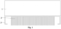
- the handle is generally arranged externally on the back of a box and occupies a certain space on the back of the box, which increases the volume and the cost of the box.
- a handle and a radiator are arranged side by side on the back of the box. Since the radiator is attached to the box, the width of the box is generally greater than the width of the radiator for the sake of appearance.
- the handle increases the size of the box in the width direction, and also increases the volume and the cost of the box.
- the object of present application is to provide an electrical apparatus, and an external handle does not additionally increase the space of the box, so as to reduce the cost of the box and improve the market competitiveness of the electrical apparatus.
- An electrical apparatus includes:
- the external handle does not occupy additional space of the box, which reduces the occupation of the area of the box after the external handle is mounted, realizes a small box, and reduces the cost of the box, thereby reducing the cost of the entire electrical apparatus and improving the market competitiveness of the entire electrical apparatus.
- the external handle is detachably fixed to the external device.
- the electrical apparatus further includes: a fastener, where a first mounting hole is provided in the external handle, a second mounting hole is correspondingly provided in the external device, and the fastener is configured to sequentially pass through the first mounting hole and the second mounting hole to fix the external handle to the external device.
- a detachable connection between the external handle and the external device is realized through the fastener, and is more stable and reliable.
- the external handle is fixed to the external device by bonding or welding.
- the external handle and the external device are connected into an integrated structure, to prevent the external handle from falling off from the external device and enhance the stability and reliability of the connection between the external handle and the external device.
- the external device includes a first device and a second device arranged side by side, the number of the external handle is two, and the two external handles are symmetrically arranged on a side face of the first device and a side face of the second device.
- a closed structure is enclosed by the external handle and the external device.
- the operator holds the external handle in the closed structure without slipping out of the external handle, so that it is stable for holding the external handle and is stable and reliable for carrying the electrical apparatus.
- the external handle is U-shaped, and each of two side walls of the external handle is arranged on the external device.
- the external handle is designed in a U-shape, which makes the structure simple and easy to realize, and ensures the closed structure enclosed by the external handle and the external device.
- an anti-skid rubber sleeve is sleeved on the external handle, and anti-skid is protrusions are provided on an outer surface of the anti-skid rubber sleeve.
- the friction between the operator and the external handle can be increased by the anti-skid protrusions, avoiding slipping on the external handle and ensuring that the operator holds the external handle more stably and reliably.
- the anti-skid rubber sleeve and the anti-skid protrusions on the outer surface of the anti-skid rubber sleeve have a certain degree of elasticity, which can avoid rigid contact between the operator and the external handle, increase the comfort of the operator when holding the external handle, and improve the protection for a hand of the operator.
- anti-skid threads are provided on a circumferential surface of the external handle.
- the friction between the operator and the external handle is increased, avoiding slipping on the external handle, thereby ensuring that the operator holds the external handle more stably and reliably.
- the external handle is made of metal.
- the external handle is made of metal, which can prevent deformation of the external handle and ensure the service life of the external handle.
- the electrical apparatus is an inverter
- the external device is a radiator or a reactor.
- the electrical apparatus includes the box, the external device and the external handle.
- the external device is fixed on the outer side of the box, and the external handle is arranged on the external device.
- the external handle is configured for carrying of the electrical apparatus.
- connection to may be a fixed connection, a detachable connection, or a connection to be integrated; may be a mechanical connection or an electric connection; may be a direct connection, or an indirect connection through an intermediary, and may be an internal connection of two components or an interaction relationship between two components.
- connection to may be a fixed connection, a detachable connection, or a connection to be integrated
- connection to be integrated may be a mechanical connection or an electric connection
- a first feature being “on” or “under” a second feature may include the first feature directly contacting the second feature, and may also include the first feature not directly contacting the second feature but contacting through another feature between the first and second features.
- the first feature being “on”, “above” and “over” the second feature includes that the first feature is directly above and obliquely above the second feature, or simply indicates that the first feature is higher than the second feature in height with reference to a horizontal line.
- the first feature being “below”, “under” and “beneath” the second feature includes that the first feature is directly below and obliquely below the second feature, or simply indicates that the first feature is lower than the second feature in height with reference to a horizontal line.
- an electrical apparatus is provided according to an embodiment of the present application.
- the electrical apparatus may be an inverter or a combiner box, but is not limited to this, and may also be other electrical apparatuses.
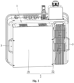
- the electrical apparatus mainly includes a box 1 and an external device 2.
- the box 1 is configured to protect and support internal electrical components, and the external device 2 may be a reactor, a radiator, an air duct, or an assembly of a radiator and an air duct.
- the external device 2 is detachably fixed to the box 1, and is electrically connected to the electrical components inside the box 1, thereby achieving the corresponding function of the external device 2.
- the electrical apparatus in order to facilitate the carrying of the electrical apparatus, further includes an external handle 3.
- the external handle 3 can be configured for carrying of the electrical apparatus, and provide a force application point for carrying the electrical apparatus for easy operation.
- a handle 3' is generally externally mounted on the back of a box 1 and occupies a certain space on the back of the box 1, which increases the volume and the cost of the box 1.
- the handle 3' and a radiator 2' are arranged side by side on the back of the box 1. Since the radiator 2' is attached to the box 1, the width of the box 1 is generally larger than the width of radiator 2' for the sake of appearance.
- the handle 3' increases the size of the box 1 in the width direction, and also increases the volume and the cost of the box 1.
- the external handle 3 is arranged on the external device 2, so that the external handle 3 does not occupy additional space of the box 1, which reduces the occupation of the area of the box 1 after the external handle 3 is mounted, realizes a small box 1, and reduces the cost of the box 1, thereby reducing the cost of the entire electrical apparatus and improving the market competitiveness of the entire electrical apparatus.
- the external handle 3 is detachably fixed to the external device 2. When the external handle 3 is damaged, it is convenient to disassemble the external handle 3 from the external device 2 for maintenance and replace the external handle 3 with a new external handle 3.
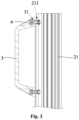
- the electrical apparatus further includes a fastener 4, and the fastener 4 is configured to detachably fix the external handle 3 to the external device 2.
- a first mounting hole 31 is provided in the external handle 3, and a second mounting hole 211 is correspondingly provided in the external device 2.
- the fastener 4 is configured to sequentially pass through the first mounting hole 31 and the second mounting hole 211 to fix the external handle 3 to the external device 2, thereby realizing a detachable connection between the external handle 3 and the external device 2.
- the fastener 4 may be a bolt, and the bolt is detachably connected.
- the bolt has advantages of high reliability and low cost.
- the external handle 3 may be detachably connected to the external device 2 through a nut. Specifically, the external device 2 passes through the first mounting hole 31 in the external handle 3. The external handle 3 is detachably connected to the external device 2 by screwing the nut on the external device 2 and abutting the nut against a side of the external handle 3.
- the external handle 3 may be fixed to the external device 2 by bonding or welding, so that the external handle 3 and the external device 2 are connected as an integrated structure, avoiding the external handle 3 from falling off from the external device 2, and enhancing the stability and reliability of the connection between the external handle 3 and the external device 2.
- the external device 2 includes a first device 21 and a second device 22 arranged side by side.
- the number of the external handle 3 is two, and the two external handles 3 are arranged symmetrically on a side face of the first device 21 and a side face of the second device 22.
- multiple external handles 3 may be provided according to actual needs, and the number is not limited to two, and may be three, four, and so on.
- a closed structure is enclosed by the external handle 3 and the external device 2.
- the operator holds the external handle 3 in the closed structure without slipping out of the external handle 3, so that it is stable for holding the external handle 3, and is stable and reliable for carrying the electrical apparatus.
- the external handle 3 is U-shaped, and each of two side walls of the external handle 3 is arranged on the external device 2, so that the structure of the external handle 3 is simple, which is convenient for processing and production, and the closed structure is enclosed by the external handle 3 and the external device 2.
- an anti-skid rubber sleeve is sleeved on the external handle 3, and anti-skid protrusions are provided on an outer surface of the anti-skid rubber sleeve.
- the anti-skid rubber sleeve and the anti-skid protrusions on the outer surface of the anti-skid rubber sleeve have a certain degree of elasticity, which can avoid rigid contact between the operator and the external handle 3, increase the comfort of the operator to hold the external handle 3, and improve the protection for a hand of the operator.
- anti-skid threads may be provided on a circumferential surface of the external handle 3, so as to increase the friction between the operator and the external handle 3, avoid slipping on the external handle 3, thereby ensuring that the operator holds the external handle 3 more stably and reliably.
- the external handle 3 is made of metal, which can prevent deformation of the external handle 3 and ensure the service life of the external handle 3.
Landscapes
- Engineering & Computer Science (AREA)
- Microelectronics & Electronic Packaging (AREA)
- Casings For Electric Apparatus (AREA)
- Surgical Instruments (AREA)
- Beans For Foods Or Fodder (AREA)
- Control And Other Processes For Unpacking Of Materials (AREA)
Applications Claiming Priority (2)
| Application Number | Priority Date | Filing Date | Title |
|---|---|---|---|
| CN202121090998.0U CN216217877U (zh) | 2021-05-20 | 2021-05-20 | 一种电气设备 |
| PCT/CN2021/134977 WO2022242105A1 (zh) | 2021-05-20 | 2021-12-02 | 一种电气设备 |
Publications (2)
| Publication Number | Publication Date |
|---|---|
| EP4344366A1 true EP4344366A1 (de) | 2024-03-27 |
| EP4344366A4 EP4344366A4 (de) | 2025-04-23 |
Family
ID=80858477
Family Applications (1)
| Application Number | Title | Priority Date | Filing Date |
|---|---|---|---|
| EP21940548.7A Withdrawn EP4344366A4 (de) | 2021-05-20 | 2021-12-02 | Elektrische vorrichtung |
Country Status (5)
| Country | Link |
|---|---|
| US (1) | US20240244776A1 (de) |
| EP (1) | EP4344366A4 (de) |
| CN (1) | CN216217877U (de) |
| AU (1) | AU2021446451A1 (de) |
| WO (1) | WO2022242105A1 (de) |
Family Cites Families (7)
| Publication number | Priority date | Publication date | Assignee | Title |
|---|---|---|---|---|
| JP5538460B2 (ja) * | 2011-04-06 | 2014-07-02 | パナソニック株式会社 | 拡張機器、およびそれを備えた情報処理システム |
| CN202354009U (zh) * | 2011-11-22 | 2012-07-25 | 无锡盛莱得新能源科技有限公司 | 散热器 |
| CN205451970U (zh) * | 2015-12-28 | 2016-08-10 | 艾威姆(天津)电气有限公司 | 一种带把手的电抗器 |
| CN208095031U (zh) * | 2018-04-09 | 2018-11-13 | 周永闯 | 一种便于安装的电气设备用散热装置 |
| KR102066917B1 (ko) * | 2018-12-24 | 2020-01-16 | 주식회사 고그린테크 | 캐리어 타입의 휴대용 전원공급 장치 |
| CN209766944U (zh) * | 2019-04-29 | 2019-12-10 | 江苏佑能实业有限公司 | 一种电气设备除湿系统 |
| CN211481825U (zh) * | 2020-03-31 | 2020-09-11 | 南昌工程学院 | 一种方便安装的电气设备散热结构 |
-
2021
- 2021-05-20 CN CN202121090998.0U patent/CN216217877U/zh active Active
- 2021-12-02 EP EP21940548.7A patent/EP4344366A4/de not_active Withdrawn
- 2021-12-02 WO PCT/CN2021/134977 patent/WO2022242105A1/zh not_active Ceased
- 2021-12-02 US US18/276,626 patent/US20240244776A1/en active Pending
- 2021-12-02 AU AU2021446451A patent/AU2021446451A1/en not_active Abandoned
Also Published As
| Publication number | Publication date |
|---|---|
| US20240244776A1 (en) | 2024-07-18 |
| EP4344366A4 (de) | 2025-04-23 |
| AU2021446451A1 (en) | 2023-08-31 |
| CN216217877U (zh) | 2022-04-05 |
| WO2022242105A1 (zh) | 2022-11-24 |
Similar Documents
| Publication | Publication Date | Title |
|---|---|---|
| EP4344366A1 (de) | Elektrische vorrichtung | |
| EP3770991B1 (de) | Batteriepack | |
| CN210290055U (zh) | 减振垫、安装结构及设备 | |
| CN113421812A (zh) | 半导体工艺设备及其承载装置 | |
| CN214578126U (zh) | 一种连接件 | |
| CN219068671U (zh) | 具有卧式继电器的bdu及电池包 | |
| CN208111940U (zh) | 具有防尘功能的低压开关柜 | |
| CN208331611U (zh) | 一种安检机的悬臂机构 | |
| CN214898713U (zh) | 一种电池柜连接安装结构 | |
| EP4568436A1 (de) | Leistungswandler | |
| CN220871605U (zh) | 一种新型千分尺恒测力装置 | |
| CN223991804U (zh) | 一种尾气处理装置的支撑结构 | |
| CN214217859U (zh) | 一种电梯轿顶用的固定结构 | |
| CN217331616U (zh) | 一种推力器测试装置 | |
| CN218041884U (zh) | 一种双束层流等离子发生器 | |
| CN218935881U (zh) | 一种显示器支架用升降锁定机构以及具有其的显示器支架 | |
| CN213536812U (zh) | 一种不锈钢盘丝输送调节支撑架 | |
| CN212647394U (zh) | 一种固定便捷的高承载显卡 | |
| CN218526552U (zh) | 一种新型音频信号发生器 | |
| CN217359961U (zh) | 电能质量监控装置 | |
| CN220051539U (zh) | 手机中框表面加工用固定装置 | |
| CN211239028U (zh) | 一种具有高承重性能的户外配电箱 | |
| CN218181429U (zh) | 一种电脑主板用快拆支架 | |
| CN215445849U (zh) | 一种计算机用可调节底座 | |
| CN212031569U (zh) | 一种电表箱内电路板的限位结构 |
Legal Events
| Date | Code | Title | Description |
|---|---|---|---|
| STAA | Information on the status of an ep patent application or granted ep patent |
Free format text: STATUS: THE INTERNATIONAL PUBLICATION HAS BEEN MADE |
|
| PUAI | Public reference made under article 153(3) epc to a published international application that has entered the european phase |
Free format text: ORIGINAL CODE: 0009012 |
|
| STAA | Information on the status of an ep patent application or granted ep patent |
Free format text: STATUS: REQUEST FOR EXAMINATION WAS MADE |
|
| 17P | Request for examination filed |
Effective date: 20230808 |
|
| AK | Designated contracting states |
Kind code of ref document: A1 Designated state(s): AL AT BE BG CH CY CZ DE DK EE ES FI FR GB GR HR HU IE IS IT LI LT LU LV MC MK MT NL NO PL PT RO RS SE SI SK SM TR |
|
| DAV | Request for validation of the european patent (deleted) | ||
| DAX | Request for extension of the european patent (deleted) | ||
| A4 | Supplementary search report drawn up and despatched |
Effective date: 20250321 |
|
| RIC1 | Information provided on ipc code assigned before grant |
Ipc: H05K 5/02 20060101AFI20250317BHEP |
|
| STAA | Information on the status of an ep patent application or granted ep patent |
Free format text: STATUS: THE APPLICATION IS DEEMED TO BE WITHDRAWN |
|
| 18D | Application deemed to be withdrawn |
Effective date: 20251009 |