EP4344262B1 - Gemeinsame nutzung von umgebungsinformationen über ein beleuchtungssteuerungsnetzwerk - Google Patents
Gemeinsame nutzung von umgebungsinformationen über ein beleuchtungssteuerungsnetzwerk Download PDFInfo
- Publication number
- EP4344262B1 EP4344262B1 EP22197270.6A EP22197270A EP4344262B1 EP 4344262 B1 EP4344262 B1 EP 4344262B1 EP 22197270 A EP22197270 A EP 22197270A EP 4344262 B1 EP4344262 B1 EP 4344262B1
- Authority
- EP
- European Patent Office
- Prior art keywords
- sensor
- lighting system
- sensor data
- external apparatus
- indication messages
- Prior art date
- Legal status (The legal status is an assumption and is not a legal conclusion. Google has not performed a legal analysis and makes no representation as to the accuracy of the status listed.)
- Active
Links
Images


Classifications
-
- H—ELECTRICITY
- H05—ELECTRIC TECHNIQUES NOT OTHERWISE PROVIDED FOR
- H05B—ELECTRIC HEATING; ELECTRIC LIGHT SOURCES NOT OTHERWISE PROVIDED FOR; CIRCUIT ARRANGEMENTS FOR ELECTRIC LIGHT SOURCES, IN GENERAL
- H05B47/00—Circuit arrangements for operating light sources in general, i.e. where the type of light source is not relevant
- H05B47/10—Controlling the light source
- H05B47/105—Controlling the light source in response to determined parameters
-
- H—ELECTRICITY
- H04—ELECTRIC COMMUNICATION TECHNIQUE
- H04L—TRANSMISSION OF DIGITAL INFORMATION, e.g. TELEGRAPHIC COMMUNICATION
- H04L12/00—Data switching networks
- H04L12/02—Details
- H04L12/12—Arrangements for remote connection or disconnection of substations or of equipment thereof
-
- H—ELECTRICITY
- H04—ELECTRIC COMMUNICATION TECHNIQUE
- H04L—TRANSMISSION OF DIGITAL INFORMATION, e.g. TELEGRAPHIC COMMUNICATION
- H04L67/00—Network arrangements or protocols for supporting network services or applications
- H04L67/01—Protocols
- H04L67/12—Protocols specially adapted for proprietary or special-purpose networking environments, e.g. medical networks, sensor networks, networks in vehicles or remote metering networks
-
- H—ELECTRICITY
- H04—ELECTRIC COMMUNICATION TECHNIQUE
- H04W—WIRELESS COMMUNICATION NETWORKS
- H04W4/00—Services specially adapted for wireless communication networks; Facilities therefor
- H04W4/30—Services specially adapted for particular environments, situations or purposes
- H04W4/38—Services specially adapted for particular environments, situations or purposes for collecting sensor information
-
- H—ELECTRICITY
- H05—ELECTRIC TECHNIQUES NOT OTHERWISE PROVIDED FOR
- H05B—ELECTRIC HEATING; ELECTRIC LIGHT SOURCES NOT OTHERWISE PROVIDED FOR; CIRCUIT ARRANGEMENTS FOR ELECTRIC LIGHT SOURCES, IN GENERAL
- H05B47/00—Circuit arrangements for operating light sources in general, i.e. where the type of light source is not relevant
- H05B47/10—Controlling the light source
- H05B47/175—Controlling the light source by remote control
- H05B47/19—Controlling the light source by remote control via wireless transmission
-
- H—ELECTRICITY
- H04—ELECTRIC COMMUNICATION TECHNIQUE
- H04W—WIRELESS COMMUNICATION NETWORKS
- H04W4/00—Services specially adapted for wireless communication networks; Facilities therefor
- H04W4/06—Selective distribution of broadcast services, e.g. multimedia broadcast multicast service [MBMS]; Services to user groups; One-way selective calling services
-
- H—ELECTRICITY
- H04—ELECTRIC COMMUNICATION TECHNIQUE
- H04W—WIRELESS COMMUNICATION NETWORKS
- H04W4/00—Services specially adapted for wireless communication networks; Facilities therefor
- H04W4/70—Services for machine-to-machine communication [M2M] or machine type communication [MTC]
-
- H—ELECTRICITY
- H04—ELECTRIC COMMUNICATION TECHNIQUE
- H04W—WIRELESS COMMUNICATION NETWORKS
- H04W4/00—Services specially adapted for wireless communication networks; Facilities therefor
- H04W4/80—Services using short range communication, e.g. near-field communication [NFC], radio-frequency identification [RFID] or low energy communication
Definitions
- the present invention relates to sharing of environmental data captured by one or more sensors that are coupled to a lighting control network.
- Many lighting systems applied for illuminating an indoor space and/or an outdoor space at least partially rely on autonomous control of light output of luminaires illuminating of the lighting system based on environmental characteristics determined via usage of one or more sensors provided in the illuminated space.
- sensors applicable for capturing control data for controlling the light output include an occupancy sensor and a light sensor: while an occupancy sensor may be applied to switch on (and keep on) lights in response to detecting occupancy in the space and to switch off (and keep off) lights in response to detecting non-occupancy in the space, a light sensor may be applied to control the light output in view of the ambient light in the space such that a desired overall light level is provided.
- occupancy sensors and light sensors enable at least partially autonomous lighting control that ensures user comfort while minimizing energy consumption.
- the illuminated space is provided with one or more sensor units that report respective sensor data captured therein over a lighting control network to a control entity, which makes use of the sensor data to control at least some aspects of respective light outputs of luminaires applied for illuminating the space e.g. issuing lighting control commands to the respective luminaires over the lighting control network
- luminaires applied for illuminating the space are provided with respective sensor units and each luminaire may apply the sensor data captured locally by the sensor unit provided therein to control at least some aspects of its light output.
- at least part of the sensor data captured at the sensor units provided at the luminaires may be shared with other entities coupled to the lighting control network.
- the sensor units may include one or more sensor of other type that are arranged for monitoring environmental characteristics such as temperature, humidity, carbon dioxide (CO 2 ) level, etc. and this data may be likewise shared with other entities coupled to the lighting control network.
- Such sensor information may be likewise applicable for assisting control of light output of the luminaires of the lighting system and/or for assisting control of building automation systems such as heating, ventilation and air-conditioning (HVAC) systems.
- HVAC heating, ventilation and air-conditioning
- availability of the sensor data that is descriptive of environmental conditions in the space via entities of the lighting control network provides interesting possibilities for making further use of such information.
- US 2015/369618 A1 discloses a system and method for interactive applications that use location-based information from a light sensor network.
- data indicating a destination location inside a geofence is received.
- the geofence represents a boundary around multiple private beacon nodes, which are associated with a light sensor network, and their associated beacon communications ranges.
- Navigation and tracking outside the geofence is based on at least one of global positioning system (GPS) signals and beacon signals received by the mobile device from at least one public beacon device within a beacon communications range of the mobile device located outside the geofence.
- Navigation and tracking inside the geofence is based on the beacon signals received by the mobile device from at least one private beacon node within the beacon communications range of the mobile device located inside the geofence and a virtual map including an area within the geofence.
- GPS global positioning system
- WO 2020/144108 A1 discloses an improved controller for providing a location-based service to an area, wherein the controller comprises a memory and a transceiver, wherein the controller is configured to: obtain a location of a mobile device associated with a person; obtain sensor data from at least one sensor arranged for monitoring the person in the area when the obtained location of the mobile device is within the area; store the sensor data in the memory; forward, via the transceiver, the stored sensor data to the mobile device when the obtained location of the mobile device is no longer within the area, and subsequently delete the sensor data from the memory.
- the invention further provides related systems for providing a location-based service to an area and related methods.
- Xiaoyu Tong & al. "A Ubiquitous Publish/Subscribe Platform for Wireless Sensor Networks with Mobile Mules", IEEE 8th International Conference on Distributed Computing in Sensor Systems (DCOSS) discloses a ubiquitous publish/subscribe system that supports data access from both mobile sensors and stationary sensors.
- the system utilizes mobile phones as data mules to relay subscriptions and published data between broker and remote sensors. It provides content-based publish/subscribe services from sensors deployed anywhere without depending on any network infrastructure.
- the application allows users to subscribe for sensing data from both stationary sensors and mobile sensors along hiking trails.
- the invention is defined by a method for distributing sensor data in accordance with claim 1, and by a sensor unit in accordance with claim 8. Further preferred embodiments are defined in the dependent claims.
- a method for distributing sensor data captured at a plurality of sensor units that are coupled to each other via a lighting control network comprising: transmitting, from the plurality of sensor units, respective sensor data captured therein over the lighting control network to a lighting system server; deriving, at the lighting system server, aggregate sensor data based on respective sensor data received from the plurality of sensor units for delivery to the plurality of sensor units and/or to an external apparatus; and transmitting, from a sensor unit of the plurality of sensor units via an external communication channel that is separate from the lighting control network, one or more sensor indication messages comprising information that provide the external apparatus receiving the one or more sensor indication messages with access to the local sensor data captured at the respective sensor unit and to at least part of the aggregate sensor data, wherein the one or more sensor indication messages include information that is descriptive of the local sensor data captured at the respective sensor unit, and the one or more sensor indication messages are transmitted together with an access token for requesting the aggregate sensor data from the lighting system server based on the access token.
- a sensor unit for operating as one of a plurality of sensor units that are coupled to each other via a lighting control network
- the sensor unit comprises: a sensor portion comprising one or more sensors for observing respective environmental characteristics at a location of the sensor unit; and a sensor control portion arranged to: derive local sensor data based on respective sensor signals received from said one or more sensors; transmit the local sensor data over the lighting control network to a lighting system server for derivation of aggregate sensor based on respective local sensor data from the plurality of sensor units therein, and transmit, via an external communication channel that is separate from the lighting control network, one or more sensor indication messages for reception by an external apparatus, the one or more sensor indication messages comprising information that provides the external apparatus receiving the one or more sensor indication messages with access to the local sensor data captured at the respective sensor unit and to at least part of the aggregate sensor data, wherein the one or more sensor indication messages include information that is descriptive of the local sensor data captured at the respective sensor unit, and the one or more sensor indication messages are transmitted together with an access token for
- a lighting system comprising a plurality of sensor units according to the example embodiment described in the foregoing; and a lighting system server wherein the lighting system server is arranged to derive aggregate sensor data based on respective local sensor data received from the plurality of sensor units for delivery to the plurality of sensor units and/or to an external apparatus.
- Figure 1 illustrates a block diagram of some components of a lighting system 100 according to an example.
- the lighting system 100 may be arranged for illuminating a space or area, which may comprise e.g. one or more indoor spaces or areas and/or one or more outdoor areas.
- the lighting system 100 is shown with luminaires 120-1, 120-2, 120-3 and 120-4 for illuminating a space or area and sensor units 140-1 and 140-2 for observing environmental characteristics in said space or area.
- the luminaires 120-1 to 120-4 represent a plurality of luminaires 120, whereas any individual luminaire may be referred to via a reference number 120-k.
- the sensor units 140-1 and 140-2 represent a plurality of sensor units 140, while any individual sensor unit may be referred to via a reference number 140-j.
- the plurality of luminaires 120 may be arranged for illuminating respective locations of the space, whereas the plurality of sensor units 140 may be arranger for observing one or more environmental characteristics in respective locations of the space illuminated by the plurality of luminaires 120. It is worth noting that the example of Figure 1 serves to illustrate the plurality of luminaires 120 and the plurality of sensor units 140 as respective operational elements of the lighting system 100, while on the other hand the illustration of Figure 1 does not serve to illustrate any physical characteristics of these elements of the lighting system 100 and/or any aspects of spatial relationship between these elements of the lighting system 100.
- the plurality of luminaires 120 and the plurality of sensor units 140 may be communicatively coupled to each other via respective wireless communication links or via a wireless communication network provided using a suitable wireless communication technique known in the art, each of the plurality of luminaires 120 and the plurality of sensor units 140 hence serving as a respective node of a lighting control network.
- the lighting system 100 may include one or more further luminaires in addition to the plurality of luminaires 120 described herein and/or one or more further sensor units in addition to the plurality of sensor units 140 described herein, which may be likewise connected to each other and to other nodes of the lighting control network.
- the lighting system 100 may further comprise a lighting system gateway 102 and a lighting system server 103.
- the lighting system gateway 102 may be communicatively coupled to the plurality of luminaires 120 and to the plurality of sensor units 140, the lighting system gateway 102 hence constituting a node of the lighting control network.
- the lighting system gateway 102 may be communicatively coupled to the lighting system server 103, where the communitive coupling between these two entities may be provided via a communication network such as the Internet.
- the lighting control network may be communicatively coupled to the lighting system server 103 via the lighting system gateway 102.
- Each of the lighting system gateway 102 and the lighting system server 103 is to be construed as a respective logical entity that may be implemented by one or more computer apparatuses.
- the lighting system gateway 102 may be implemented by a single computer apparatus and/or the lighting system server 103 may be implemented by one or more computer apparatuses that may be arranged to provide a cloud computing service.
- Figure 2 illustrates a block diagram of some (logical) components of a sensor unit 140-j according to an example, comprising a sensor portion 142-j for observing one or more environmental characteristics in the space illuminated by the plurality of luminaires 120, a communication portion 143-j for wireless communication with other elements of the lighting control network and a sensor control portion 144-j for controlling at least one aspect of operation of the sensor unit 140-j and/or for processing sensor data captured at the sensor portion 142-j.
- the sensor unit 140-j may comprise an apparatus comprising a processor and a memory, where the memory is arranged to store computer program code that, when executed by the processor, causes the apparatus to operate as the sensor control portion 144-j, thereby implementing operations of the sensor control portion 144-j. More detailed examples of using the processor and the memory for implementing the sensor unit 140-j are described later in this text with references to Figure 9 .
- the communication portion 143-j may enable wireless communication with other apparatuses to allow for exchange of data and/or control information between the sensor unit 140-j and other elements of the lighting control network, while the communication portion 143-j may further enable wireless communication with other apparatuses that may not constitute nodes of lighting control network.
- the communication portion 143-j may comprise a respective communication apparatus, e.g. a wireless transceiver, that is capable of communicating with respective communication apparatuses provided in other elements of the lighting control network using one or more predefined wireless communication techniques or protocols.
- the wireless communication may be carried out via using a suitable short-range wireless communication technique known in the art that enables communication over ranges from a few meters up to a few hundred meters.
- suitable short-range wireless communication techniques include Bluetooth, Bluetooth Low-Energy (BLE), ZigBee, WLAN/Wi-Fi according to an IEEE 802.11 family of standards, etc.
- BLE Bluetooth Low-Energy
- ZigBee ZigBee
- WLAN/Wi-Fi WLAN/Wi-Fi according to an IEEE 802.11 family of standards, etc.
- the choice of the wireless communication technique and network topology applied for a specific implementation of the lighting control network may depend e.g. on the required communication range and/or requirements with respect to energy-efficiency of the communication apparatuses.
- the sensor unit 140-j or an element thereof may have a device ID, e.g. an address, a serial number, a name, etc. assigned thereto, where the device ID assigned to the sensor unit 140-j may be referred to as a sensor unit ID of the sensor unit 140-j.
- the sensor unit ID may be stored, for example, in the memory provided in the sensor unit 140-j and it may be applied, for example, to identify the respective sensor unit 140-j in communication between elements of the lighting control network.
- the sensor portion 142-j may comprise one or more sensors arranged to observe respective environmental characteristics in the space illuminated by the plurality of luminaires 120.
- the one or more sensors of the sensor portion 142-j may be communicatively coupled, e.g. via respective electrical wires, to the sensor control portion 144-j in order to provide respective sensor signals thereto.
- the one or more sensors of the sensor portion 142-j may comprise respective sensors of different type, e.g. one or more of the following sensors:
- the sensor control portion 144-j may record or derive respective sensor indications based on respective sensor signals received from the sensor portion 142-j, which may be referred to as respective local sensor indications since they are based on sensor data captured locally at the sensor unit 140-j, whereas the local sensor indications recorded or derived at the sensor unit 140-j may be jointly referred to as local sensor data.
- the sensor control portion 144-j may transfer the local sensor indications recorded or derived therein over the lighting control network to the lighting system gateway 102 for centralized lighting control implemented therein, whereas the lighting system gateway 102 may further transfer at least part of the sensor indications obtained from the sensor unit 140-j to the lighting system server 103 for processing therein.
- the sensor control portion 144-j may further store the local sensor indications into the memory provided in the sensor unit 140-j for subsequent use.
- Examples of local sensor indications recorded or derived in the sensor control portion 144-j include deriving local occupancy state indications (i.e. respective indications of one of occupancy or non-occupancy) based on a motion sensor signal received from a motion sensor of the sensor portion 142-j, recording or deriving local light level indications based on a light sensor signal received from the sensor portion 142-j, deriving one or more local sound parameters (e.g.
- any of the plurality of luminaires 120 are described via references to the single luminaire 120-k, whereas these characteristics pertain to each of the plurality of luminaires 120, unless explicitly described otherwise.
- certain characteristic of structure and operation of the luminaire 120-k are described herein for completeness of the description, whereas details of luminaire characteristics and operation are outside the scope of the present invention.
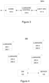
- Figure 3 illustrates a block diagram of some (logical) components of a luminaire 120-k according to an example, where the luminaire 120-k may comprise at least one light source 121-k for providing light output of the luminaire 120-k, a communication portion 123-k for wireless communication with other elements of the lighting control network, and a luminaire control portion 124-k for controlling at least one aspect of operation of the luminaire 120-k.
- the luminaire 120-k may comprise at least one light source 121-k for providing light output of the luminaire 120-k, a communication portion 123-k for wireless communication with other elements of the lighting control network, and a luminaire control portion 124-k for controlling at least one aspect of operation of the luminaire 120-k.
- the at least one light source 121-k may comprise one or more light emitting diodes (LEDs) and the luminaire control portion 124-k may comprise or it may be provided as a LED driver device, whereas in another non-limiting example the at least one light source 121-k may comprise one or more fluorescent lamps and the luminaire control portion 124-k may comprise or it may be provided as an electronic ballast.
- the communication portion 123-k may be similar to the communication portion 143-j described in the foregoing, thereby enabling exchange of data and/or control information between the luminaire 120-k and other elements of the lighting control network.
- the luminaire control portion 124-k may control one or more aspects of light output provided from the at least one light source 121-k in accordance with lighting control commands received over the lighting control network from the lighting system gateway 102.
- the luminaire 120-k may comprise an apparatus comprising a processor and a memory, where the memory is arranged to store computer program code that, when executed by the processor, causes the apparatus to operate as the luminaire control portion 124-k according to the present disclosure. More detailed examples of using the processor and the memory for implementing the luminaire control portion 124-k are described later in this text with references to Figure 9 .
- the luminaire 120-k or an element thereof may have a device ID, e.g. an address, a serial number, a name, etc. assigned thereto, where the device ID assigned to the luminaire 120-k may be referred to as a luminaire ID of the luminaire 120-k.
- the luminaire ID may be stored, for example, in the memory provided in the luminaire 120-k and it may be applied, for example, to identify the respective luminaire 120-k in communication between elements of the lighting control network.
- the lighting system gateway 102 may comprise a lighting control means (e.g. a lighting control portion) for controlling one or more aspects of respective light outputs of the plurality of luminaires based at least in part on the respective sensor indications received from the plurality of sensor units 140.
- a lighting control means e.g. a lighting control portion
- the collection of respective sensor indications received from the plurality of sensor units 140 may be referred to as sensor data and the lighting control means may apply a preprogrammed lighting control logic that defines a manner of controlling the respective light outputs from the plurality of luminaires 120 based on the sensor data.
- the preprogrammed lighting control logic may define switching on the light output of a luminaire 120-k as a response to the sensor data associated with the luminaire 120-k indicating occupancy (after a period of non-occupancy) and define switching off the light output of the luminaire 120-k as a response to the sensor data associated with the luminaire 120-k indicating non-occupancy (after a period of occupancy).
- the preprogrammed lighting control logic may include one or more predefined lighting control rules, where each lighting control rule may define a respective pair of a triggering condition and a lighting control action to be carried out as a response to an occurrence of the triggering condition, where the triggering condition may directly or indirectly pertain to sensor indications included in the sensor data received at the lighting system gateway 102 from the plurality of sensor units 140.
- the control means may enforce the lighting control actions occurring from application of the lighting control logic therein via transmitting respective lighting control commands over the lighting control network to the respective luminaire 120-k, where the lighting control portion 120-k adjusts the light output from the at least light source 121-k in accordance with lighting control commands received from the lighting system gateway 102.
- the lighting control means in the lighting system gateway 102 may transfer the sensor data received from the plurality of sensor units 140 to the lighting system server 103 for further processing and/or analysis therein.
- the respective sensor control portion 144-j in each sensor unit 140-j may implement respective preprogrammed lighting control logic (instead of the lighting system gateway 102 implementing the lighting control logic therein) to control the respective light outputs of a respective subset of the plurality of luminaires 120. Consequently, in such a scenario the lighting control pertaining to a luminaire 120-k may involve the sensor unit 140-j transmitting lighting control commands corresponding to the lighting control actions arising from application of the respective lighting control logic therein over the lighting control network to the luminaire 120-k. In another variation of the lighting control approach described above, the lighting control logic pertaining to a luminaire 120-k may be implemented by the lighting control portion 124-k of the respective luminaire 120.
- each sensor unit 140-j may (also) transfer at least part of the respective local sensor indications recorded or derived therein to those ones of the plurality luminaires 120 that are associated with the respective sensor unit 140-j. Consequently, lighting control actions arising from application of the lighting control logic in a luminaire 120-k may be directly applied at the respective luminaire 120-k.
- Figure 4 illustrates a block diagram of some components of a lighting system 200 according to an example, which is similar to the lighting system 100 apart from a different arrangement of the sensor units in relation to the luminaires.
- the lighting system 200 is shown with luminaires 220-1, 220-1, 220-3 and 220-4 for illuminating said space, whereas respective sensor units 240-1, 240-2, 240-3 and 240-4 for observing environmental characteristics in said space or area are integrated to the respective ones of the luminaires 220-1, 220-1, 220-3 and 220-4.
- the luminaires 220-1 to 220-4 represent a plurality of luminaires 220, where any individual luminaire may be referred to via a reference number 220-k.
- the sensor units 240-1 to 240-4 represent a plurality of sensor units 240, where any individual sensor unit may be referred to via a reference number 240-k.
- Each of the luminaires 220-k may be arranged for illuminating a respective location of said area or space, whereas the respective sensor unit 240-k may be arranged for observing one or more environmental characteristics in the respective location.
- the example of Figure 4 serves to illustrate the plurality of luminaires 220 and the plurality of sensor units 240 integrated thereto as respective operational elements of the lighting system 200, while on the other hand the illustration of Figure 4 does not serve to illustrate any physical characteristics of these elements of the lighting system 200 and/or any aspects of spatial relationship between these elements of the lighting system 200.
- FIG. 5 illustrates a block diagram of some (logical) components of a luminaire 220-k with the sensor unit 240-k integrated thereto according to an example.
- the sensor unit 240-k comprises a sensor portion 142-k for observing one or more environmental characteristics in the space illuminated by the luminaire 220-k, a communication portion 143-k for wireless communication with other elements of the lighting control network and a sensor control portion 144-k for controlling at least one aspect of operation of the sensor unit 240-k and/or for processing sensor data captured at the sensor portion 142-k.
- the luminaire 220-k comprises the at least one light source 121-k for providing light output of the luminaire 220-k and the luminaire control portion 124-k for controlling at least one aspect of operation of the luminaire 220-k.
- the sensor portion 142-k, the communication portion 143-k and the sensor control portion 144-k may be similar to the corresponding elements described in the foregoing with references to the sensor unit 140-j with the exception that the sensor control portion 144-k may further transfer at least part of the local sensor data to the luminaire control portion 124-k e.g. via one or more electrical wires to enable lighting control therein.
- the sensor data passed from the sensor control portion 144-k to the luminaire control portion 124-k may comprise local occupancy indications and/or local light level indications.
- the at least one light source 121-k and the luminaire control portion 124-k at the luminaire 220-k may be similar to the corresponding elements described in the foregoing with references to the luminaire 120-k, where the luminaire control portion 124-k may apply the preprogrammed lighting control logic for the luminaire 220-k based on the local sensor indications obtained from the sensor control portion 144-k of the sensor unit 240-k integrated to the luminaire 220-k and the luminaire control portion 124-k may further apply the lighting control actions arising from application of the lighting control logic at the luminaire 220-k, thereby providing at least partially autonomous lighting control at the luminaire 220-k.
- the luminaire 220-k as illustrated in the example of Figure 5 does not include a dedicated communication portion but the luminaire control 124-k may be able to apply the communication portion 143-k of the sensor unit 240-k for wireless communication with the other nodes of the lighting control network.
- the communication portion 143-k in the sensor unit 240-k may be omitted and the luminaire 220-k may include a communication portion similar to the communication portion 123-k described in the foregoing with references to the luminaire 120-k, whereas the sensor control portion 144-k in the sensor unit 240-k may be able to apply the communication portion provided in the luminaire 220-k for wireless communication with other elements of the lighting control network.
- the lighting control network that serves to connect the plurality of luminaires 120, 220 and/or the plurality of sensor units 140, 240 to each other and to the lighting system gateway 102 may be implemented as a wired communication network or as a wired communication bus.
- Figure 6 illustrates a block diagram of some components of a lighting system 100' according to an example, which is similar to the lighting system 100 apart from the communicative coupling between the plurality of luminaires 120 and the plurality of sensor units 140.
- the luminaires 120-1, 120-2, 120-3 and 120-4 represent the plurality of luminaires 120 and the sensor units 140-1 and 140-2 represent the plurality of sensor units 140, and the plurality of luminaires 120, the plurality of sensor units 140 and the lighting system gateway 102 are coupled to each other via a wired communication network or a wired communication bus.
- the respective sensor control portion 144-j in each sensor unit 140-j may implement respective preprogrammed lighting control logic for controlling the respective light outputs of a respective subset of the plurality of luminaires 120. Consequently, in such a scenario the lighting control pertaining to a luminaire 120-k may involve the sensor unit 140-j transmitting lighting control commands corresponding to the lighting control actions arising from application of the respective lighting control logic therein over the lighting control network to the luminaire 120-k.
- the lighting control logic pertaining to a luminaire 120-k may be implemented by the lighting control portion 124-k of the respective luminaire 120, whereas each sensor unit 140-j may transfer at least part of the respective local sensor indications recorded or derived therein to those ones of the plurality luminaires 120 that are associated with the respective sensor unit 140-j. Consequently, lighting control actions arising from application of the lighting control logic in a luminaire 120-k may be directly applied at the respective luminaire 120-k.
- the lighting control network may be provided using a predefined lighting control protocol, such as the Digital Addressable Lighting Interface (DALI) specified in a series of technical standards IEC 62386, whereas the respective communication portions 123-k, 143-j, 143-k in the nodes of the lighting control network may be arranged to provide communication over the lighting control network in accordance with the applicable lighting control protocol. Also in such variants of the lighting system 100, 200 the respective communication portions 123-k, 143-j, 143-k may be also capable of wireless communication with other apparatuses that may not constitute nodes of lighting control network.
- DALI Digital Addressable Lighting Interface
- the lighting control means in the lighting system gateway 102 may transfer at least part of the sensor data received from the sensor units 140, 240 to the lighting system server 103 for further processing and/or analysis therein.
- the respective sensor data originating from a certain sensor unit 140-j, 240-k may be considered as respective local sensor data in viewpoint of the respective sensor unit 140-j, 240-k, in viewpoint of the lighting system server 103 this sensor data may be considered as respective remote sensor data.
- respective local sensor indications originating from a certain sensor unit 140-j, 240-k may be considered at the lighting system server 103 as respective remote sensor indications.
- the lighting system server 103 includes analysis means for processing and/or analyzing at least part of the respective remote sensor data originating from the plurality of sensor units 140, 240 in order to estimate overall environmental characteristics across the space or area illuminated by the lighting system 100, 100', 200.
- the analysis means is arranged to derive one or more aggregate sensor indications based on respective remote sensor indications originating from sensors of certain type provided at respective sensor portions 143-j, 143-k of the sensor units 140-j, 240-k, where the one or more aggregate sensor indications derived via operation of the analysis means may be jointly referred to as aggregate sensor data and the one or more aggregate sensor values may include one or more of the following:
- each aggregate sensor indication may be derived based on respective remote sensor indications originating from respective sensors of a certain type at the plurality of sensor units 140, 240 (or at a predefined subset thereof), e.g. from respective motion sensors, from respective light sensors, from respective temperature sensors, from respective humidity sensors, from respective sound sensors, from respective CO 2 sensors, from respective VOC sensors, etc.
- the global sensor indication may be derived as a predefined function of respective remote sensor indications originating from sensors of a certain type at the plurality of sensor units 140, 240, whereas a zone-specific sensor indication may be derived as a predefined function of respective remote sensor indications originating from sensors of a certain type at a respective predefined subset of the plurality of sensor units 140, 240.
- the predefined function may include an average, a median, a minimum or a maximum of the remote sensor indications under consideration or another statistical value derivable based on the remote sensor indications under consideration.
- Concrete non-limiting examples of aggregate sensor indications derivable via the analysis means in the lighting system server 103 include the following:
- the analysis means may derive the one or more aggregate sensor indications, for example, according to a predefined schedule and it may transmit information that is descriptive of the derived one or more aggregate sensor indications to the plurality of sensors units 140, 240 via the lighting system gateway 102.
- the information that is descriptive of the derived one or more aggregate sensor indications may be transferred from the lighting system server 103 to the lighting system gateway 102 via the communication network connecting these two entities, whereas the lighting system gateway 102 may transmit (e.g. broadcast) this information over the lighting control network to the plurality of sensor units 140, 240.
- the sensor unit 140-j, 240-k further shares at least part of the sensor data available therein with an external apparatus over a wireless link or a wireless network.
- the wireless connection applied for sharing the sensor data may be the same applied for connecting to the lighting control network or it may be different from the one applied for connecting to the lighting control network.
- the sharing of sensor data may be carried out via the communication portion 143-j, 143-k of the sensor unit 140-j, 240-k.
- the sharing of sensor data is provided via one or more sensor indication messages transmitted from the sensor unit 140-j, 240-k and the sharing of sensor data is carried out using the following approach: the sensor unit 140-j, 240-k transmits one or more sensor indication messages that include information that is descriptive of the local sensor data recorded or derived at the sensor unit 140-j, 240-k and the one or more sensor indication messages are transmitted together with access information for obtaining the one or more aggregate sensor indications from the lighting system server 103.
- sharing of the sensor data may be carried out e.g. one of the following approaches:
- the one or more sensor indication messages transmitted from the sensor unit 140-j, 240-k may include information that is descriptive of one or more local sensor indications recorded or derived via operation of the sensor control portion 144-j, 144-k at the sensor unit 140-j, 240-k based on the respective sensor signal received from the sensor portion 142-j, 142-k.
- While the local sensor data acquired at the sensor unit 140-j, 240-k may be primarily intended to serve as basis for lighting control within the lighting system 100, 100', 200, such sharing of the local sensor data may be applied to make at least part of this sensor data available for external apparatuses locally at proximity of the sensor unit 140-j, 240-k.
- the information delivered in the one or more sensor indication messages may include information that is descriptive of local sensor data captured at the sensor unit 140-j, 240-k.
- this information may include respective local sensor indications recorded or derived based on respective sensor signals obtained from all sensors provided in the sensor portion 142-j, 142-k
- the information delivered in the one or more sensor indication messages may include information that is descriptive of respective local sensor indications recorded or derived based on respective sensor signals obtained from a predefined subset of the sensors provided in the sensor portion 142-j, 142-k.
- the latter approach may be applicable as a straightforward approach for limiting access to information that may be considered sensitive (such as occupancy information) and/or to avoid allocating transmission bandwidth for conveying information that is considered to provide limited added value for user(s) of the external apparatus 150.
- the local sensor data serving as basis for the information included in the one or more sensor indication messages may include a predefined number of local sensor indications most recently recorded or derived at the sensor unit 140-j, 240-k.
- the information transmitted in the one or more sensor indication messages may include these local sensor indications as such or one or more values derived based on these local sensor indications.
- the information transmitted in the one or more sensor indication messages may be descriptive of an aspect of current environmental conditions at the location of the sensor unit 140-j, 240-k, such as occupancy, light level, temperature, humidity, sound level, CO 2 level, respective levels of one or more VOCs, etc.
- the sensor unit 140-j, 240-k may transmit the one or more sensor indication messages according to a predefined schedule, e.g. at predefined time intervals. If such periodical transmission at predefined time intervals is applied, the time interval may be chosen according to circumstances and the interval may be chosen e.g. from a range from a few seconds to a few minutes. Consequently, the sensor unit 140-j, 240-k may transmit a set of one or more sensor indication messages according to the predefined schedule, where the number of sensor indication messages may depend on the amount of information to be transmitted in relation to the information transfer capacity enabled by an underlying data transmission mechanism.
- the information included in the one or more sensor indication messages may be formatted according to any suitable manner known by the sensor unit 140-j, 240-k transmitting the one or more sensor indication messages and the external apparatus 150 receiving the one or more sensor indication messages.
- the sensor control portion 144-j, 144-k may arrange the information to be conveyed in the one or more sensor indication messages into respective sensor data elements that are suited for transport in one or more protocol data units (PDUs) of an underlying data transport protocol, whereas the external apparatus is provided with a capability to extract the information from the sensor data elements from the received PDUs. This may involve providing the external apparatus with an executable program (provided e.g.
- the one or more sensor indication messages may be conveyed using advertising messages of the BLE advertising channel PDUs, which may be also referred to as BLE advertising packets, as BLE advertisements or as BLE adverts.
- the one or more sensor indication messages may be transmitted (e.g. broadcast) in a respective user-definable data fields of one or more BLE advertising packets.
- the external apparatus 150 may comprise a user device such as a mobile phone (e.g. a smartphone), a smartwatch, a tablet computer, a laptop computer, a desktop computer, etc. that is able to display the information conveyed in the one or more sensor indication messages to a user of the user device.
- the external apparatus 150 may comprise a display apparatus provided in a respective location of the space illuminated by the lighting system 100, 100', 200.
- the one or more sensor indication messages transmitted from the sensor unit 140-j, 240-k may further include information that is descriptive of at least part of the aggregate sensor data available at the sensor unit 140-j, 240-k.
- the one or more sensor indication messages transmitted from the sensor unit 140-j, 240-k may include information that is descriptive of the local sensor data captured at the sensor unit 140-j, 240-k together with one or more aggregate sensor indications available at the sensor unit 140-j, 240-k.
- the one or more sensor indication messages may include information that is descriptive of respective aggregate sensor indications originating from sensors of any type, whereas in another example the one or more sensor indication messages may include information that is descriptive of aggregate sensor indications that pertain to sensor data originating from sensors of a predefined subset of sensor types.
- the latter approach may be applicable as a straightforward approach for limiting access to information that may be considered sensitive (such as occupancy information) and/or to avoid allocating transmission bandwidth for conveying information that is considered to provide limited added value for user(s) of the external apparatus 150.
- the aggregate sensor data serving as basis for the information included in the one or more sensor indication messages may include a predefined number of aggregate sensor indications most recently received from the lighting system server 103.
- the information transmitted in the one or more sensor indication messages may include these aggregate sensor indications as such or one or more values derived based on these aggregate sensor indications.
- the aggregate sensor indications that pertain to sensors of a certain type and that are available at the sensor unit 140-j, 240-k may comprise a global sensor indication that is descriptive of respective environmental condition across the space or area illuminated by the lighting system 100, 100', 200 and/or one or more zone-specific sensor indications that are descriptive of the respective environmental condition at respective portions of the space or area illuminated by the lighting system 100, 100', 200.
- the one or more sensor indication messages according to the second example may convey information that is may descriptive of an aspect of current environmental conditions at the location of the sensor unit 140-j, 240-k, such as occupancy, light level, temperature, humidity, sound level, CO 2 level, respective levels of one or more VOCs, etc.
- the one or more sensor indication messages according to the second example may provide the external apparatus 150 with access to the data that is descriptive of environmental characteristics at or close to its location together with access to data that is descriptive of the corresponding environmental characteristics elsewhere in the space or area illuminated by the lighting system 100, 100', 200.
- the information displayed to the user(s) via the display of the user apparatus 150 may include e.g. respective indications of one or more of the occupancy level, the temperature, the humidity, the sound level (e.g. a noise level), the CO 2 level, the VOC levels at or close to the current location of the user apparatus together with respective indications obtained for one or more sub-portions of the space illuminated by the lighting system 100, 100', 200 and/or to the space illuminated by the lighting system 100, 100', 200 in its entirety. Consequently, the user(s) may make use of the displayed information, for example, to identify a location or a sub-portion of said space where the environmental conditions of interest have the best match with her/his preferences.
- Figure 7B illustrates a block diagram showing the components of the lighting system 100 also shown in the illustration of Figure 1 together with the external apparatus 150, where the arrangement illustrated via the example of Figure 7B may serve as the framework for a third example regarding delivery of the sensor data from the sensor unit 140-j, 240-k to the external apparatus 150.
- the external apparatus 150 may receive the one or more sensor indication messages from the sensor unit 140-2 of the lighting system 100, whereas in general case the one or more sensor indication messages may originate from any sensor unit 140-j of the lighting system 100 or 100' or from any sensor unit 240-k of the lighting system 200.
- the external apparatus 150 may be communicatively coupled to the lighting system server 103 via a communication network such as the Internet or the external apparatus 150 may be capable of establishing a communicative coupling to the lighting system server 103 via such communication network for transfer of control information and (sensor) data.
- the access token may comprise the sensor unit ID assigned to the respective sensor unit 140-j, 240-k.
- the PDUs applied for transferring the one or more sensor indication messages may further include the sensor unit ID assigned to the respective sensor unit 140-j, 240-k and, consequently, the external apparatus 150 may receive the sensor unit ID of the respective sensor unit 140-j, 240-k together with the one or more sensor indication messages.
- the sensor unit ID may be (additionally or alternatively) included in the one or more sensor indication messages transmitted from the respective sensor unit 140-j, 240-k.
- the external apparatus 150 may request the aggregate sensor data from the lighting system server 103 based on the sensor unit ID received from the sensor unit 140-j, 240-k.
- the external apparatus 150 may send a request for the aggregate sensor data to the lighting system server 103, where the request includes the sensor unit ID received from the respective sensor unit 140-j, 240-k.
- the external apparatus 150 may have a priori knowledge of the address of the lighting system server 103 or the external apparatus 150 may receive the address of the lighting system server 103 via a user interface of the external apparatus.
- the one or more sensor indication messages may further include the address of the lighting system server 103 and, consequently, the external apparatus 150 may receive the address of the lighting system server 103 together with the local sensor data from the sensor unit 140-j, 240-k.
- the lighting system server 103 finds the sensor unit ID received in the request originating from the external apparatus 150 to be a valid one (e.g. one of one or more predefined sensor unit IDs), the lighting system server 103 may respond to the request by transmitting the aggregate sensor data to the external apparatus 150, whereas in case of the request including an invalid sensor unit ID, no data may be transmitted from the lighting system server 103 to the external apparatus 103.
- the external apparatus 150 may be authorized to access only a predefined subset of the aggregate sensor data available at the lighting system server 103 in dependence of the sensor unit ID included in the request, e.g.
- a respective predefined subset of global sensor indications e.g. ones that pertain to a respective predefined subset of sensor types
- a respective predefined subset of zone-specific sensor indications e.g. ones that pertain to respective sub-area(s) of the space illuminated by the lighting system 100, 100', 200.
- knowledge of the sensor unit ID of the sensor unit 140-j, 240-k having provided the one or more sensor indication messages serves as an indication of the external apparatus 150 being located in relatively close proximity of the respective sensor unit 140-j, 240-k, which may be considered in the third example as a sufficient prerequisite for the external apparatus 150 being allowed to receive at least part of the aggregate sensor data from the lighting system server 103.
- the access token may comprise an ID associated with the external apparatus 150, such as a user ID assigned to a user of the external apparatus 150 or a device ID assigned to the external apparatus 150.
- the request for the aggregate sensor data sent from the external apparatus 150 may further include the user ID, whereas the lighting system server 103 may respond to the request by transmitting the aggregate sensor data to the external apparatus 150 only in case the user ID received in the request matches one of predefined user IDs that represent users that are authorized to access the aggregate sensor data.
- the one or more sensor indication messages may be transmitted from the sensor unit 140-j, 240-k in response to an activation message received from the external apparatus 150.
- the external apparatus 150 may transmit (e.g. broadcast) the activation message as an indication of a wish to receive the one or more sensor indication messages from the sensor unit 140-j, 240-k in its vicinity.
- the activation message may comprise an activation token to be verified by the sensor unit 140-j, 240-k and the sensor unit 140-j, 240-k may initiate transmission of the one or more sensor indication messages in response to determining that the activation token received in the activation message is a valid one.
- the lighting system server 103 may determine the location of external apparatus 150 with respect to these multiple sensor units 140-j, 240 and, consequently, with a priori knowledge of the respective locations of these multiple sensor units 140-j, 240-k (e.g. based on their respective sensor unit IDs) the lighting system server 103 may estimate the location of the external apparatus 150 within the space or area illuminated by the lighting system 100, 100', 200, which may enable estimation of environmental conditions at the location of the external apparatus 150 at improved accuracy and/or reliability.
- the operations described with reference to block 306 may be omitted e.g. in a scenario where the external apparatus 150 requests the aggregate sensor data from the lighting system server 130 (e.g. in accordance with the third and fourth examples described in the foregoing).
- the computer program code 425 may comprise computer-executable instructions that implement at least some aspects of controlling operation of the respective one of the luminaire 120-k, the sensor unit 140-j, 240-k, the external apparatus 150, the lighting system gateway 102 or the lighting system server 103 when loaded into the processor 410.
- the computer program code 425 may include a computer program consisting of one or more sequences of one or more instructions.
- the processor 410 is able to load and execute the computer program by reading the one or more sequences of one or more instructions included therein from the memory 420.
- the apparatus 400 may comprise at least one processor 410 and at least one memory 420 including the computer program code 425 for one or more programs, the at least one memory 420 and the computer program code 425 configured to, with the at least one processor 410, cause the apparatus 400 to perform at least some aspects of controlling operation of the respective one of the luminaire 120-k, the sensor unit 140-j, 240-k, the external apparatus 150, the lighting system gateway 102 or the lighting system server 103.
- references(s) to a processor herein should not be understood to encompass only programmable processors, but also dedicated circuits such as field-programmable gate arrays (FPGA), application specific circuits (ASIC), signal processors, etc.
- FPGA field-programmable gate arrays
- ASIC application specific circuits
- signal processors etc.
Landscapes
- Engineering & Computer Science (AREA)
- Computer Networks & Wireless Communication (AREA)
- Signal Processing (AREA)
- Health & Medical Sciences (AREA)
- Computing Systems (AREA)
- General Health & Medical Sciences (AREA)
- Medical Informatics (AREA)
- Circuit Arrangement For Electric Light Sources In General (AREA)
Claims (10)
- Verfahren (300) zum Verteilen von Sensordaten, die an einer Vielzahl von Sensoreinheiten (140, 240), die über ein Beleuchtungssteuerungsnetzwerk miteinander gekoppelt sind, erfasst werden, wobei das Verfahren (300) umfasst:Übertragen (302), von der Vielzahl von Sensoreinheiten (140, 240), jeweiliger darin erfasster lokaler Sensordaten über das Beleuchtungssteuerungsnetzwerk an einen Beleuchtungssystemserver (103);Ableiten (304), an dem Beleuchtungssystemserver (103), aggregierter Sensordaten basierend auf jeweiligen Sensordaten, die von der Vielzahl von Sensoreinheiten (140, 240) empfangen werden, zur Lieferung an die Vielzahl von Sensoreinheiten (140, 240) und/oder an eine externe Einrichtung (150) undÜbertragen (308), von einer Sensoreinheit (140-j, 240-k) der Vielzahl von Sensoreinheiten (140, 240) über einen externen Kommunikationskanal, der vom Beleuchtungssteuerungsnetzwerk getrennt ist, einer oder mehrerer Sensorangabenachricht(en), die Informationen umfasst/umfassen, die der externen Einrichtung (150), die die eine oder die mehreren Sensorangabenachricht(en) empfängt, Zugriff auf die lokalen Sensordaten, die an der jeweiligen Sensoreinheit (140-j, 240-k) erfasst werden, und auf mindestens einen Teil der aggregierten Sensordaten bereitstellen,dadurch gekennzeichnet, dass die eine oder die mehreren Sensorangabenachricht(en) Informationen einschließt/einschließen, die die lokalen Sensordaten beschreiben, die an der jeweiligen Sensoreinheit (140-j, 240-k) erfasst werden, und die eine oder die mehreren Sensorangabenachricht(en) zusammen mit einem Zugriffs-Token zum Anfordern der aggregierten Sensordaten von dem Beleuchtungssystemserver (103) basierend auf dem Zugriffs-Token übertragen werden.
- Verfahren (300) nach Anspruch 1, wobei das Übertragen (308) der einen oder der mehreren Sensorangabenachricht(en) das Rundsenden einer oder mehrerer Protokolldateneinheit(en), die die eine oder die mehreren Sensorangabenachricht(en) trägt/tragen, umfasst.
- Verfahren (300) nach Anspruch 2, wobei die eine oder die mehreren Protokolldateneinheit(en) eine oder mehrere Bluetooth-Low-Energy-Ankündigungsprotokolldateneinheit(en) umfasst/umfassen.
- Verfahren nach einem der Ansprüche 1 bis 3, wobei das Zugriffs-Token eine Vorrichtungs-ID der jeweiligen Sensoreinheit (140-j, 240-k) umfasst.
- Verfahren (300) nach einem der Ansprüche 1 bis 4, wobei die eine oder die mehreren Sensorangabenachricht(en) eine Adresse des Beleuchtungssystemservers (103) einschließt/einschließen.
- Verfahren (300) nach einem der Ansprüche 1 bis 5, das ferner umfasst:Übertragen, von der externen Einrichtung (150) an den Beleuchtungssystemserver (103), einer Anforderung zum Empfangen der aggregierten Sensordaten von dem Beleuchtungssystemserver (103), wobei die Anforderung das Zugriffs-Token einschließt; undÜbertragen, von dem Beleuchtungssystemserver (103) an die externe Einrichtung (150), mindestens eines Teils der aggregierten Sensordaten als Reaktion auf das Bestimmen, dass das Zugriffs-Token ein gültiges ist.
- Verfahren (300) nach einem der Ansprüche 1 bis 6, das ferner umfasst:Übertragen, von der externen Einrichtung (150) an die jeweilige Sensoreinheit (140-j, 240-k), einer Aktivierungsnachricht, die ein Aktivierungs-Token umfasst; undÜbertragen der einen oder der mehreren Sensorangabenachricht(en) von der jeweiligen Sensoreinheit (140-j, 240-k) als Reaktion auf das Bestimmen, dass das Aktivierungs-Token, das in der Aktivierungsnachricht empfangen wird, ein gültiges ist.
- Sensoreinheit (140-j, 240-k) zum Arbeiten als eine einer Vielzahl von Sensoreinheiten (140, 240), die über ein Beleuchtungssteuerungsnetzwerk miteinander gekoppelt sind, wobei die Sensoreinheit (140-j, 240-k) umfasst:einen Sensorabschnitt (142-j, 142-k), der einen oder mehrere Sensor(en) zum Beobachten jeweiliger Umgebungscharakteristiken an einem Ort der Sensoreinheit (140-j, 240-k) umfasst; undeinen Sensorsteuerabschnitt (144-j, 144-k), der angeordnet ist zum:Ableiten lokaler Sensordaten basierend auf jeweiligen Sensorsignalen, die von dem einen oder den mehreren Sensoren empfangen werden,Übertragen der lokalen Sensordaten über das Beleuchtungssteuerungsnetzwerk an einen Beleuchtungssystemserver (103) zur Ableitung aggregierter Sensordaten basierend auf jeweiligen lokalen Sensordaten von der Vielzahl von Sensoreinheiten (140, 240) darin undÜbertragen, über einen externen Kommunikationskanal, der von dem Beleuchtungssteuerungsnetzwerk getrennt ist, einer oder mehrerer Sensorangabenachricht(en) zum Empfang durch eine externe Einrichtung (150), wobei die eine oder die mehreren Sensorangabenachricht(en) Informationen umfasst/umfassen, die der externen Einrichtung (150), die die eine oder die mehreren Sensorangabenachricht(en) empfängt, Zugriff auf die lokalen Sensordaten, die an der jeweiligen Sensoreinheit (140-j, 240-k) erfasst werden, und auf mindestens einen Teil der aggregierten Sensordaten bereitstellen,dadurch gekennzeichnet, dass die eine oder die mehreren Sensorangabenachricht(en) Informationen einschließt/einschließen, die die lokalen Sensordaten beschreiben, die an der jeweiligen Sensoreinheit (140-j, 240-k) erfasst werden, und die eine oder die mehreren Sensorangabenachricht(en) zusammen mit einem Zugriffs-Token zum Anfordern der aggregierten Sensordaten von dem Beleuchtungssystemserver (103) basierend auf dem Zugriffs-Token übertragen werden.
- Beleuchtungssystem (100, 100', 200), das umfasst:eine Vielzahl von Sensoreinheiten (140, 240) nach Anspruch 8 undden Beleuchtungssystemserver (103),wobei der Beleuchtungssystemserver (103) zum Ableiten der aggregierten Sensordaten basierend auf jeweiligen Sensordaten, die von der Vielzahl von Sensoreinheiten (140, 240) empfangen werden, zur Lieferung an die Vielzahl von Sensoreinheiten (140, 240) und/oder an eine externe Einrichtung (150) angeordnet ist.
- Beleuchtungssystem (100, 100', 200) nach Anspruch 9,
das ferner die externe Einrichtung (150) umfasst, die angeordnet ist zum:Empfangen der jeweiligen einen oder mehreren Sensorangabenachricht(en), die von einer der Vielzahl von Sensoreinheiten (140, 240) übertragen wird/werden, und Übertragen, an den Beleuchtungssystemserver (103), einer Anforderung zum Empfangen der aggregierten Sensordaten von dem Beleuchtungssystemserver (103), wobei die Anforderung das Zugriffs-Token einschließt,wobei der Beleuchtungssystemserver (103) zum Übertragen, an die externe Einrichtung (150), mindestens eines Teils der aggregierten Sensordaten als Reaktion auf das Bestimmen, dass das Zugriffs-Token ein gültiges ist, angeordnet ist.
Priority Applications (1)
| Application Number | Priority Date | Filing Date | Title |
|---|---|---|---|
| EP22197270.6A EP4344262B1 (de) | 2022-09-23 | 2022-09-23 | Gemeinsame nutzung von umgebungsinformationen über ein beleuchtungssteuerungsnetzwerk |
Applications Claiming Priority (1)
| Application Number | Priority Date | Filing Date | Title |
|---|---|---|---|
| EP22197270.6A EP4344262B1 (de) | 2022-09-23 | 2022-09-23 | Gemeinsame nutzung von umgebungsinformationen über ein beleuchtungssteuerungsnetzwerk |
Publications (3)
| Publication Number | Publication Date |
|---|---|
| EP4344262A1 EP4344262A1 (de) | 2024-03-27 |
| EP4344262B1 true EP4344262B1 (de) | 2025-06-25 |
| EP4344262C0 EP4344262C0 (de) | 2025-06-25 |
Family
ID=83438775
Family Applications (1)
| Application Number | Title | Priority Date | Filing Date |
|---|---|---|---|
| EP22197270.6A Active EP4344262B1 (de) | 2022-09-23 | 2022-09-23 | Gemeinsame nutzung von umgebungsinformationen über ein beleuchtungssteuerungsnetzwerk |
Country Status (1)
| Country | Link |
|---|---|
| EP (1) | EP4344262B1 (de) |
Family Cites Families (2)
| Publication number | Priority date | Publication date | Assignee | Title |
|---|---|---|---|---|
| US10422650B2 (en) * | 2014-06-18 | 2019-09-24 | Verizon Patent And Licensing Inc. | Application framework for interactive wireless sensor networks |
| JP7446315B2 (ja) * | 2019-01-07 | 2024-03-08 | シグニファイ ホールディング ビー ヴィ | エリアにロケーションベースのサービスを提供するためのコントローラ、システム及び方法 |
-
2022
- 2022-09-23 EP EP22197270.6A patent/EP4344262B1/de active Active
Also Published As
| Publication number | Publication date |
|---|---|
| EP4344262C0 (de) | 2025-06-25 |
| EP4344262A1 (de) | 2024-03-27 |
Similar Documents
| Publication | Publication Date | Title |
|---|---|---|
| US20220239622A1 (en) | Efficient Network Stack for Wireless Application Protocols | |
| US10685194B2 (en) | Asset tracking using active wireless tags that report via a local network of connected beacons | |
| US10230466B2 (en) | System and method for communication with a mobile device via a positioning system including RF communication devices and modulated beacon light sources | |
| US10205606B2 (en) | Mesh over-the-air (OTA) luminaire firmware update | |
| CA2982946C (en) | Mesh over-the-air (ota) driver update using site profile based multiple platform image | |
| US9325827B2 (en) | Method and apparatus for providing services via a modular smart illumination device | |
| KR20200043543A (ko) | 메시 네트워크 어드레싱 | |
| JP5962349B2 (ja) | 無線通信システム、無線通信方法、及び無線通信装置 | |
| JP2014049003A (ja) | 情報管理サーバ、コンテンツ管理システム及びコンテンツ管理プログラム | |
| CA2970362A1 (en) | Mesh over-the-air (ota) luminaire firmware update | |
| EP4344262B1 (de) | Gemeinsame nutzung von umgebungsinformationen über ein beleuchtungssteuerungsnetzwerk | |
| GB2553798A (en) | Automation system | |
| EP4054295A1 (de) | Gemeinsame verwendung von statusinformationen für ein beleuchtungssteuerungsnetzwerk | |
| KR20100051423A (ko) | 싱크 노드와 소스 노드를 포함하는 근거리 무선 통신 시스템, 방법 및 그 싱크 노드 |
Legal Events
| Date | Code | Title | Description |
|---|---|---|---|
| PUAI | Public reference made under article 153(3) epc to a published international application that has entered the european phase |
Free format text: ORIGINAL CODE: 0009012 |
|
| STAA | Information on the status of an ep patent application or granted ep patent |
Free format text: STATUS: THE APPLICATION HAS BEEN PUBLISHED |
|
| AK | Designated contracting states |
Kind code of ref document: A1 Designated state(s): AL AT BE BG CH CY CZ DE DK EE ES FI FR GB GR HR HU IE IS IT LI LT LU LV MC MK MT NL NO PL PT RO RS SE SI SK SM TR |
|
| STAA | Information on the status of an ep patent application or granted ep patent |
Free format text: STATUS: REQUEST FOR EXAMINATION WAS MADE |
|
| 17P | Request for examination filed |
Effective date: 20240927 |
|
| RBV | Designated contracting states (corrected) |
Designated state(s): AL AT BE BG CH CY CZ DE DK EE ES FI FR GB GR HR HU IE IS IT LI LT LU LV MC MK MT NL NO PL PT RO RS SE SI SK SM TR |
|
| GRAP | Despatch of communication of intention to grant a patent |
Free format text: ORIGINAL CODE: EPIDOSNIGR1 |
|
| STAA | Information on the status of an ep patent application or granted ep patent |
Free format text: STATUS: GRANT OF PATENT IS INTENDED |
|
| RIC1 | Information provided on ipc code assigned before grant |
Ipc: H04W 4/06 20090101ALI20250220BHEP Ipc: H04L 67/12 20220101ALI20250220BHEP Ipc: H04L 12/12 20060101ALI20250220BHEP Ipc: H05B 47/19 20200101ALI20250220BHEP Ipc: H05B 47/105 20200101ALI20250220BHEP Ipc: H04W 4/80 20180101ALI20250220BHEP Ipc: H04W 4/38 20180101AFI20250220BHEP |
|
| INTG | Intention to grant announced |
Effective date: 20250310 |
|
| GRAS | Grant fee paid |
Free format text: ORIGINAL CODE: EPIDOSNIGR3 |
|
| GRAA | (expected) grant |
Free format text: ORIGINAL CODE: 0009210 |
|
| STAA | Information on the status of an ep patent application or granted ep patent |
Free format text: STATUS: THE PATENT HAS BEEN GRANTED |
|
| AK | Designated contracting states |
Kind code of ref document: B1 Designated state(s): AL AT BE BG CH CY CZ DE DK EE ES FI FR GB GR HR HU IE IS IT LI LT LU LV MC MK MT NL NO PL PT RO RS SE SI SK SM TR |
|
| REG | Reference to a national code |
Ref country code: GB Ref legal event code: FG4D |
|
| REG | Reference to a national code |
Ref country code: CH Ref legal event code: EP |
|
| REG | Reference to a national code |
Ref country code: DE Ref legal event code: R096 Ref document number: 602022016364 Country of ref document: DE |
|
| REG | Reference to a national code |
Ref country code: CH Ref legal event code: EP |
|
| REG | Reference to a national code |
Ref country code: IE Ref legal event code: FG4D |
|
| U01 | Request for unitary effect filed |
Effective date: 20250717 |
|
| U07 | Unitary effect registered |
Designated state(s): AT BE BG DE DK EE FI FR IT LT LU LV MT NL PT RO SE SI Effective date: 20250724 |
|
| PG25 | Lapsed in a contracting state [announced via postgrant information from national office to epo] |
Ref country code: NO Free format text: LAPSE BECAUSE OF FAILURE TO SUBMIT A TRANSLATION OF THE DESCRIPTION OR TO PAY THE FEE WITHIN THE PRESCRIBED TIME-LIMIT Effective date: 20250925 Ref country code: GR Free format text: LAPSE BECAUSE OF FAILURE TO SUBMIT A TRANSLATION OF THE DESCRIPTION OR TO PAY THE FEE WITHIN THE PRESCRIBED TIME-LIMIT Effective date: 20250926 |
|
| PG25 | Lapsed in a contracting state [announced via postgrant information from national office to epo] |
Ref country code: HR Free format text: LAPSE BECAUSE OF FAILURE TO SUBMIT A TRANSLATION OF THE DESCRIPTION OR TO PAY THE FEE WITHIN THE PRESCRIBED TIME-LIMIT Effective date: 20250625 |
|
| PG25 | Lapsed in a contracting state [announced via postgrant information from national office to epo] |
Ref country code: RS Free format text: LAPSE BECAUSE OF FAILURE TO SUBMIT A TRANSLATION OF THE DESCRIPTION OR TO PAY THE FEE WITHIN THE PRESCRIBED TIME-LIMIT Effective date: 20250925 |
|
| U20 | Renewal fee for the european patent with unitary effect paid |
Year of fee payment: 4 Effective date: 20250929 |
|
| PG25 | Lapsed in a contracting state [announced via postgrant information from national office to epo] |
Ref country code: IS Free format text: LAPSE BECAUSE OF FAILURE TO SUBMIT A TRANSLATION OF THE DESCRIPTION OR TO PAY THE FEE WITHIN THE PRESCRIBED TIME-LIMIT Effective date: 20251025 |
|
| PG25 | Lapsed in a contracting state [announced via postgrant information from national office to epo] |
Ref country code: SM Free format text: LAPSE BECAUSE OF FAILURE TO SUBMIT A TRANSLATION OF THE DESCRIPTION OR TO PAY THE FEE WITHIN THE PRESCRIBED TIME-LIMIT Effective date: 20250625 |
|
| PG25 | Lapsed in a contracting state [announced via postgrant information from national office to epo] |
Ref country code: CZ Free format text: LAPSE BECAUSE OF FAILURE TO SUBMIT A TRANSLATION OF THE DESCRIPTION OR TO PAY THE FEE WITHIN THE PRESCRIBED TIME-LIMIT Effective date: 20250625 |
|
| PG25 | Lapsed in a contracting state [announced via postgrant information from national office to epo] |
Ref country code: PL Free format text: LAPSE BECAUSE OF FAILURE TO SUBMIT A TRANSLATION OF THE DESCRIPTION OR TO PAY THE FEE WITHIN THE PRESCRIBED TIME-LIMIT Effective date: 20250625 |
|
| PG25 | Lapsed in a contracting state [announced via postgrant information from national office to epo] |
Ref country code: SK Free format text: LAPSE BECAUSE OF FAILURE TO SUBMIT A TRANSLATION OF THE DESCRIPTION OR TO PAY THE FEE WITHIN THE PRESCRIBED TIME-LIMIT Effective date: 20250625 |
|
| PG25 | Lapsed in a contracting state [announced via postgrant information from national office to epo] |
Ref country code: ES Free format text: LAPSE BECAUSE OF FAILURE TO SUBMIT A TRANSLATION OF THE DESCRIPTION OR TO PAY THE FEE WITHIN THE PRESCRIBED TIME-LIMIT Effective date: 20250625 |