EP4343926A1 - Cooling structure, battery unit, and cooling structure manufacturing method - Google Patents
Cooling structure, battery unit, and cooling structure manufacturing method Download PDFInfo
- Publication number
- EP4343926A1 EP4343926A1 EP22804484.8A EP22804484A EP4343926A1 EP 4343926 A1 EP4343926 A1 EP 4343926A1 EP 22804484 A EP22804484 A EP 22804484A EP 4343926 A1 EP4343926 A1 EP 4343926A1
- Authority
- EP
- European Patent Office
- Prior art keywords
- flow path
- cooling structure
- upper lid
- forming member
- press forming
- Prior art date
- Legal status (The legal status is an assumption and is not a legal conclusion. Google has not performed a legal analysis and makes no representation as to the accuracy of the status listed.)
- Pending
Links
Images







Classifications
-
- H—ELECTRICITY
- H01—ELECTRIC ELEMENTS
- H01M—PROCESSES OR MEANS, e.g. BATTERIES, FOR THE DIRECT CONVERSION OF CHEMICAL ENERGY INTO ELECTRICAL ENERGY
- H01M10/00—Secondary cells; Manufacture thereof
- H01M10/60—Heating or cooling; Temperature control
- H01M10/65—Means for temperature control structurally associated with the cells
- H01M10/655—Solid structures for heat exchange or heat conduction
- H01M10/6556—Solid parts with flow channel passages or pipes for heat exchange
-
- B—PERFORMING OPERATIONS; TRANSPORTING
- B23—MACHINE TOOLS; METAL-WORKING NOT OTHERWISE PROVIDED FOR
- B23K—SOLDERING OR UNSOLDERING; WELDING; CLADDING OR PLATING BY SOLDERING OR WELDING; CUTTING BY APPLYING HEAT LOCALLY, e.g. FLAME CUTTING; WORKING BY LASER BEAM
- B23K26/00—Working by laser beam, e.g. welding, cutting or boring
- B23K26/20—Bonding
- B23K26/206—Laser sealing
-
- B—PERFORMING OPERATIONS; TRANSPORTING
- B23—MACHINE TOOLS; METAL-WORKING NOT OTHERWISE PROVIDED FOR
- B23K—SOLDERING OR UNSOLDERING; WELDING; CLADDING OR PLATING BY SOLDERING OR WELDING; CUTTING BY APPLYING HEAT LOCALLY, e.g. FLAME CUTTING; WORKING BY LASER BEAM
- B23K26/00—Working by laser beam, e.g. welding, cutting or boring
- B23K26/20—Bonding
- B23K26/21—Bonding by welding
-
- B—PERFORMING OPERATIONS; TRANSPORTING
- B23—MACHINE TOOLS; METAL-WORKING NOT OTHERWISE PROVIDED FOR
- B23K—SOLDERING OR UNSOLDERING; WELDING; CLADDING OR PLATING BY SOLDERING OR WELDING; CUTTING BY APPLYING HEAT LOCALLY, e.g. FLAME CUTTING; WORKING BY LASER BEAM
- B23K26/00—Working by laser beam, e.g. welding, cutting or boring
- B23K26/20—Bonding
- B23K26/21—Bonding by welding
- B23K26/24—Seam welding
- B23K26/244—Overlap seam welding
-
- B—PERFORMING OPERATIONS; TRANSPORTING
- B23—MACHINE TOOLS; METAL-WORKING NOT OTHERWISE PROVIDED FOR
- B23K—SOLDERING OR UNSOLDERING; WELDING; CLADDING OR PLATING BY SOLDERING OR WELDING; CUTTING BY APPLYING HEAT LOCALLY, e.g. FLAME CUTTING; WORKING BY LASER BEAM
- B23K26/00—Working by laser beam, e.g. welding, cutting or boring
- B23K26/20—Bonding
- B23K26/32—Bonding taking account of the properties of the material involved
-
- H—ELECTRICITY
- H01—ELECTRIC ELEMENTS
- H01M—PROCESSES OR MEANS, e.g. BATTERIES, FOR THE DIRECT CONVERSION OF CHEMICAL ENERGY INTO ELECTRICAL ENERGY
- H01M10/00—Secondary cells; Manufacture thereof
- H01M10/04—Construction or manufacture in general
- H01M10/0481—Compression means other than compression means for stacks of electrodes and separators
-
- H—ELECTRICITY
- H01—ELECTRIC ELEMENTS
- H01M—PROCESSES OR MEANS, e.g. BATTERIES, FOR THE DIRECT CONVERSION OF CHEMICAL ENERGY INTO ELECTRICAL ENERGY
- H01M10/00—Secondary cells; Manufacture thereof
- H01M10/60—Heating or cooling; Temperature control
- H01M10/62—Heating or cooling; Temperature control specially adapted for specific applications
- H01M10/625—Vehicles
-
- H—ELECTRICITY
- H01—ELECTRIC ELEMENTS
- H01M—PROCESSES OR MEANS, e.g. BATTERIES, FOR THE DIRECT CONVERSION OF CHEMICAL ENERGY INTO ELECTRICAL ENERGY
- H01M10/00—Secondary cells; Manufacture thereof
- H01M10/60—Heating or cooling; Temperature control
- H01M10/65—Means for temperature control structurally associated with the cells
- H01M10/651—Means for temperature control structurally associated with the cells characterised by parameters specified by a numeric value or mathematical formula, e.g. ratios, sizes or concentrations
-
- H—ELECTRICITY
- H01—ELECTRIC ELEMENTS
- H01M—PROCESSES OR MEANS, e.g. BATTERIES, FOR THE DIRECT CONVERSION OF CHEMICAL ENERGY INTO ELECTRICAL ENERGY
- H01M10/00—Secondary cells; Manufacture thereof
- H01M10/60—Heating or cooling; Temperature control
- H01M10/65—Means for temperature control structurally associated with the cells
- H01M10/653—Means for temperature control structurally associated with the cells characterised by electrically insulating or thermally conductive materials
-
- H—ELECTRICITY
- H01—ELECTRIC ELEMENTS
- H01M—PROCESSES OR MEANS, e.g. BATTERIES, FOR THE DIRECT CONVERSION OF CHEMICAL ENERGY INTO ELECTRICAL ENERGY
- H01M10/00—Secondary cells; Manufacture thereof
- H01M10/60—Heating or cooling; Temperature control
- H01M10/65—Means for temperature control structurally associated with the cells
- H01M10/655—Solid structures for heat exchange or heat conduction
- H01M10/6554—Rods or plates
-
- H—ELECTRICITY
- H01—ELECTRIC ELEMENTS
- H01M—PROCESSES OR MEANS, e.g. BATTERIES, FOR THE DIRECT CONVERSION OF CHEMICAL ENERGY INTO ELECTRICAL ENERGY
- H01M10/00—Secondary cells; Manufacture thereof
- H01M10/60—Heating or cooling; Temperature control
- H01M10/65—Means for temperature control structurally associated with the cells
- H01M10/656—Means for temperature control structurally associated with the cells characterised by the type of heat-exchange fluid
- H01M10/6567—Liquids
- H01M10/6568—Liquids characterised by flow circuits, e.g. loops, located externally to the cells or cell casings
-
- H—ELECTRICITY
- H01—ELECTRIC ELEMENTS
- H01M—PROCESSES OR MEANS, e.g. BATTERIES, FOR THE DIRECT CONVERSION OF CHEMICAL ENERGY INTO ELECTRICAL ENERGY
- H01M50/00—Constructional details or processes of manufacture of the non-active parts of electrochemical cells other than fuel cells, e.g. hybrid cells
- H01M50/20—Mountings; Secondary casings or frames; Racks, modules or packs; Suspension devices; Shock absorbers; Transport or carrying devices; Holders
- H01M50/218—Mountings; Secondary casings or frames; Racks, modules or packs; Suspension devices; Shock absorbers; Transport or carrying devices; Holders characterised by the material
- H01M50/22—Mountings; Secondary casings or frames; Racks, modules or packs; Suspension devices; Shock absorbers; Transport or carrying devices; Holders characterised by the material of the casings or racks
- H01M50/222—Inorganic material
- H01M50/224—Metals
-
- B—PERFORMING OPERATIONS; TRANSPORTING
- B23—MACHINE TOOLS; METAL-WORKING NOT OTHERWISE PROVIDED FOR
- B23K—SOLDERING OR UNSOLDERING; WELDING; CLADDING OR PLATING BY SOLDERING OR WELDING; CUTTING BY APPLYING HEAT LOCALLY, e.g. FLAME CUTTING; WORKING BY LASER BEAM
- B23K2101/00—Articles made by soldering, welding or cutting
- B23K2101/04—Tubular or hollow articles
- B23K2101/14—Heat exchangers
-
- B—PERFORMING OPERATIONS; TRANSPORTING
- B23—MACHINE TOOLS; METAL-WORKING NOT OTHERWISE PROVIDED FOR
- B23K—SOLDERING OR UNSOLDERING; WELDING; CLADDING OR PLATING BY SOLDERING OR WELDING; CUTTING BY APPLYING HEAT LOCALLY, e.g. FLAME CUTTING; WORKING BY LASER BEAM
- B23K2101/00—Articles made by soldering, welding or cutting
- B23K2101/34—Coated articles ; Surface treated articles
-
- B—PERFORMING OPERATIONS; TRANSPORTING
- B23—MACHINE TOOLS; METAL-WORKING NOT OTHERWISE PROVIDED FOR
- B23K—SOLDERING OR UNSOLDERING; WELDING; CLADDING OR PLATING BY SOLDERING OR WELDING; CUTTING BY APPLYING HEAT LOCALLY, e.g. FLAME CUTTING; WORKING BY LASER BEAM
- B23K2101/00—Articles made by soldering, welding or cutting
- B23K2101/36—Electric or electronic devices
-
- B—PERFORMING OPERATIONS; TRANSPORTING
- B23—MACHINE TOOLS; METAL-WORKING NOT OTHERWISE PROVIDED FOR
- B23K—SOLDERING OR UNSOLDERING; WELDING; CLADDING OR PLATING BY SOLDERING OR WELDING; CUTTING BY APPLYING HEAT LOCALLY, e.g. FLAME CUTTING; WORKING BY LASER BEAM
- B23K2103/00—Materials to be soldered, welded or cut
- B23K2103/08—Non-ferrous metals or alloys
-
- B—PERFORMING OPERATIONS; TRANSPORTING
- B23—MACHINE TOOLS; METAL-WORKING NOT OTHERWISE PROVIDED FOR
- B23K—SOLDERING OR UNSOLDERING; WELDING; CLADDING OR PLATING BY SOLDERING OR WELDING; CUTTING BY APPLYING HEAT LOCALLY, e.g. FLAME CUTTING; WORKING BY LASER BEAM
- B23K2103/00—Materials to be soldered, welded or cut
- B23K2103/08—Non-ferrous metals or alloys
- B23K2103/10—Aluminium or alloys thereof
-
- B—PERFORMING OPERATIONS; TRANSPORTING
- B23—MACHINE TOOLS; METAL-WORKING NOT OTHERWISE PROVIDED FOR
- B23K—SOLDERING OR UNSOLDERING; WELDING; CLADDING OR PLATING BY SOLDERING OR WELDING; CUTTING BY APPLYING HEAT LOCALLY, e.g. FLAME CUTTING; WORKING BY LASER BEAM
- B23K2103/00—Materials to be soldered, welded or cut
- B23K2103/08—Non-ferrous metals or alloys
- B23K2103/12—Copper or alloys thereof
-
- B—PERFORMING OPERATIONS; TRANSPORTING
- B23—MACHINE TOOLS; METAL-WORKING NOT OTHERWISE PROVIDED FOR
- B23K—SOLDERING OR UNSOLDERING; WELDING; CLADDING OR PLATING BY SOLDERING OR WELDING; CUTTING BY APPLYING HEAT LOCALLY, e.g. FLAME CUTTING; WORKING BY LASER BEAM
- B23K2103/00—Materials to be soldered, welded or cut
- B23K2103/16—Composite materials
- B23K2103/166—Multilayered materials
-
- H—ELECTRICITY
- H01—ELECTRIC ELEMENTS
- H01M—PROCESSES OR MEANS, e.g. BATTERIES, FOR THE DIRECT CONVERSION OF CHEMICAL ENERGY INTO ELECTRICAL ENERGY
- H01M10/00—Secondary cells; Manufacture thereof
- H01M10/60—Heating or cooling; Temperature control
- H01M10/61—Types of temperature control
- H01M10/613—Cooling or keeping cold
-
- Y—GENERAL TAGGING OF NEW TECHNOLOGICAL DEVELOPMENTS; GENERAL TAGGING OF CROSS-SECTIONAL TECHNOLOGIES SPANNING OVER SEVERAL SECTIONS OF THE IPC; TECHNICAL SUBJECTS COVERED BY FORMER USPC CROSS-REFERENCE ART COLLECTIONS [XRACs] AND DIGESTS
- Y02—TECHNOLOGIES OR APPLICATIONS FOR MITIGATION OR ADAPTATION AGAINST CLIMATE CHANGE
- Y02E—REDUCTION OF GREENHOUSE GAS [GHG] EMISSIONS, RELATED TO ENERGY GENERATION, TRANSMISSION OR DISTRIBUTION
- Y02E60/00—Enabling technologies; Technologies with a potential or indirect contribution to GHG emissions mitigation
- Y02E60/10—Energy storage using batteries
Definitions
- the present invention relates to a cooling structure, a battery unit, and a manufacturing method of the cooling structure.
- the outer wall portion and the cooling structure of the water-cooling type battery pack are often made of aluminum having high corrosion resistance to a cooling liquid.
- aluminum has a problem in terms of cost.
- since aluminum is soft, it is difficult to reduce the weight of the outer wall by thinning the outer wall while securing the outer wall strength in a cooling structure formed of an aluminum plate.
- the material of these members is a steel sheet, it is possible to provide a water-cooling type battery pack at low cost and reduce the weight thereof.
- the battery pack and the cooling structure are disposed on the bottom surface of the automobile, the battery pack and the cooling structure are exposed to an external environment. Therefore, the members constituting the battery pack and the cooling structure are required to have a corrosion resistance equivalent to that of the suspension parts of the automobile.
- corrosion resistance to a cooling liquid is referred to as cooling liquid corrosion resistance or inner surface corrosion resistance
- corrosion resistance to an external environment is referred to as outer surface corrosion resistance.
- corrosion resistance is simply referred to, this refers to both cooling liquid corrosion resistance and outer surface corrosion resistance.
- Plating is one of means for enhancing corrosion resistance of a steel sheet. For example, by forming plating such as Al-based plating on the surface of the steel sheet, both cooling liquid corrosion resistance and outer surface corrosion resistance can be enhanced.
- the cooling structure is required to have high cooling efficiency.
- liquid tightness of the flow path is also required to maintain cooling efficiency and suppress LLC leakage.
- Spot welding is usually used as means for firmly joining plated steel sheets.
- spot welding is point joining, it is difficult to ensure liquid tightness of the flow path.
- the sealer may be deteriorated by the LLC. Therefore, in manufacturing the cooling structure, a joining method capable of securing liquid tightness of the flow path while maintaining corrosion resistance is also required.
- Patent Document 3 a cooler is manufactured by brazing an aluminum-plated steel sheet.
- the technique of Patent Document 3 is assumed to be applied only to a small device, and it is difficult to cope with coolers of various sizes. Further, in Patent Document 3, it is a problem to prevent deformation of the exterior member, and it is difficult to change joining means of the exterior member.
- an object of the present invention is to provide a cooling structure having high cooling efficiency, excellent liquid tightness of a flow path, and further having high cooling liquid corrosion resistance and outer surface corrosion resistance, a battery unit, and a manufacturing method of the cooling structure.
- the gist of the present invention is as follows.
- the present invention it is possible to provide a cooling structure having high cooling efficiency, excellent liquid tightness of a flow path, and further having high cooling liquid corrosion resistance and outer surface corrosion resistance, a battery unit, and a manufacturing method of the cooling structure.
- a cooling structure 1 includes a press forming member 11, a flow path upper lid 12, and a laser weld 13 that joins these components.
- the laser weld is a joint portion formed of a linear bead (that is, a weld metal).
- FIG. 1 is a cross-sectional view of the cooling structure 1
- FIG. 2A is a plane view of the cooling structure 1 from the press forming member 11 side.
- the press forming member 11 is a member obtained by press forming a plated steel sheet, and includes a groove part 111 and a bank part 112 provided around the groove part 111.
- the bottom of the press forming member 11 and the periphery thereof are groove parts 111
- the top portion of the press forming member 11 and the periphery thereof are bank parts 112.
- the flow path upper lid 12 is a member forming a flat cooling surface, has a flat sheet shape, and is overlapped at a position covering the groove part 111 of the press forming member 11.
- the press forming member 11 and the flow path upper lid 12 are joined by a laser weld 13.
- the laser weld 13 joins opposing surfaces of the flow path upper lid 12 and the bank part 112 of the press forming member 11.
- the flow path upper lid 12 and the groove part 111 form a flow path 14 through which the cooling liquid is capable of flowing.
- any cooling liquid such as LLC introduced from a cooling liquid inlet 143 can flow to a cooling liquid outlet 144. Accordingly, it is possible to cool the flow path upper lid 12 as a cooling surface and an arbitrary object in contact with the flow path upper lid 12.
- FIG. 2A any cooling liquid such as LLC introduced from a cooling liquid inlet 143
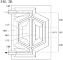
- the plurality of partial flow paths 1411 extending along the first direction includes a parallel flow path portion 141 arranged in the second direction orthogonal to the first direction, and a flow path connecting portion 142 that communicates these partial flow paths 1411.
- the first direction is, for example, a longitudinal direction or a lateral direction of the cooling structure 1. A specific configuration of the flow path 14 will be described later.
- Shapes of the bank part 112 and the groove part 111 are not particularly limited.
- the cross sections of the bank part 112 and the groove part 111 are substantially rectangular (trapezoidal).
- the cross-sectional shape of one or both of the bank part 112 and the groove part 111 of the press forming member 11 may be a partially circular shape or a substantially circular arc shape.
- the press forming member 11 in which the cross-sectional shapes of both the bank part 112 and the groove part 111 are partially circular or substantially arc is referred to as a corrugated plate.
- the radius of curvature of the bank part 112 at the contact section between the flow path upper lid 12 and the bank part 112, that is, at the laser weld 13 may be 15 mm or less, 13 mm or less, or 10 mm or less.
- the radius of curvature of the bank part 112 in the laser weld 13 is smaller, the width W of the partial flow path 1411 is widened, and the cooling efficiency of the cooling structure 1 is further enhanced.
- the radius of curvature of the bank part 112 at the contact section between the flow path upper lid 12 and the bank part 112 is measured in a cross section of the partial flow path 1411 parallel to the second direction orthogonal to the first direction that is the extending direction of the partial flow path 1411 and perpendicular to the surface of the flow path upper lid 12.
- the radius of a circle R including a total of three points including the center of the weld metal and two points 1 mm away from the center of the weld metal along the second direction at the center of the bank part 112 in the sheet thickness direction is the radius of curvature of the bank part 112 at the contact section between the flow path upper lid 12 and the bank part 112.
- the press forming member 11 and the flow path upper lid 12 are plated steel sheets having a base steel sheet and Al plating provided on the surface of the base steel sheet.
- the configuration of the Al plated steel sheet is not particularly limited, but a preferred configuration is as follows.
- the sheet thickness of the plated steel sheet forming the press forming member 11 and the flow path upper lid 12 may be 0.3 mm or more. By setting the sheet thickness to 0.3 mm or more, the press formability and the rigidity of the cooling structure 1 can be further improved.
- the sheet thickness of the plated steel sheet forming the press forming member 11 and the flow path upper lid 12 may be 0.4 mm or more, 0.6 mm or more, or 0.8 mm or more.
- the sheet thickness of the plated steel sheet forming the press forming member 11 and the flow path upper lid 12 may be 1.2 mm or less.
- the sheet thickness of the press forming member 11 By setting the sheet thickness of the press forming member 11 to 1.2 mm or less, it is easier to bring the press forming member 11 into close contact with the flow path upper lid 12, and the liquid tightness of the flow path is further improved.
- the cooling efficiency of the cooling structure 1 can be further improved.
- the sheet thicknesses of the press forming member 11 and the flow path upper lid 12 may be 1.1 mm or less, 1.0 mm or less, or 0.8 mm or less.
- the press forming member 11 and the flow path upper lid 12 may have different sheet thicknesses. Since the cooling efficiency increases as the sheet thickness decreases, it is preferable that the flow path upper lid 12 is thin.
- the base steel sheet of the plated steel sheet forming the press forming member 11 and the flow path upper lid 12 is not particularly limited.
- the base steel sheet of the flow path upper lid 12 may be a high strength steel sheet having a tensile strength of 980 MPa or more.
- the base steel sheet of the press forming member 11 may be a soft steel sheet having a tensile strength of about 270 MPa, for example, SPCC.
- Various forms according to the shape and application of the cooling structure 1 can be applied to the base steel sheet forming the press forming member 11 and the flow path upper lid 12.
- Examples of the base steel sheet include IF steel to which Ti, Nb, B, or the like is added, Al-k steel, Cr-added steel, stainless steel, high tensile strength steel sheets, low-carbon steel, medium-carbon steel, high-carbon steel, alloy steel, and the like.
- the Al-based plating of the plated steel sheet forming the press forming member 11 and the flow path upper lid 12 is, for example, two-component or multicomponent plating in which the Al content is 70 mass% or more. It is preferable that the Al-based plating is two-component or multicomponent plating in which Al content is 70 to 98 mass% and Si content is 2.0 to 15 mass%. Si content of the Al-based plating may be 3.0 mass% or more, 4.0 mass% or more, or 5.0 mass% or more. Si content of the Al-based plating may be 14 mass% or less, 12 mass% or less, or 10 mass% or less. By setting the Si content to be within the above range, the workability and corrosion resistance of the Al-based plated steel sheet can be extremely enhanced.
- a trace amount of Fe, Ni, Co, or the like may be interposed.
- Mg, Sn, mischmetal, Sb, Zn, Cr, W, V, Mo, and the like may be contained in the Al-based plating.
- the manufacturing method of the Al-based plated steel sheet is not particularly limited.
- the Al-based plating can be provided by hot-dip plating by a sendzimir method, an all-radiant method, or the like, melt flux plating, electro plating, or vapor deposition plating.
- the film thickness of the Al-based plating is not particularly limited.
- the film thickness of the Al-based plating may be 10 ⁇ m or more, 12 ⁇ m or more, 15 ⁇ m or more, or 20 ⁇ m or more.
- the film thickness of the Al-based plating may be 60 ⁇ m or less, 50 ⁇ m or less, or 40 ⁇ m or less.
- Al can be provided on a surface of the weld metal in the laser weld 13 by setting the film thickness of the Al-based plating, the conditions of laser welding, and the interval between the press forming member and the flow path upper lid within a prescribed range.
- chemical conversion treatment is performed on the surface of the Al-based plated steel sheet or the like.
- the chemical conversion treatment generally known chemical conversion treatment can be used.
- a chemical conversion coating film containing one or more selected from the group including a Zr-based component, a Ti-based component and a Si-based component as a main component (for example, 50 mass% or more in terms of mass%) is preferably formed.
- the chemical conversion coating film includes two or more of the Zr-based component, the Ti-based component and the Si-based component, a total content of the components may be 50 mass% or more.
- the chemical conversion coating film may contain an organic component.
- the "main component" of the chemical conversion coating film means a component having a proportion of 50 mass% or more in the chemical conversion coating film.
- Examples of the chemical conversion coating film include those listed in Japanese Unexamined Patent Application, First Publication No. 2008-115442 , Japanese Unexamined Patent Application, First Publication No. 2013-7108 , Japanese Unexamined Patent Application, First Publication No. 2004-232040 , Japanese Patent Publication No. 3302676 , Japanese Patent Publication No. 4776458 , and Japanese Patent Publication No. 5336002 . Therefore, the chemical conversion coating films listed in these publications can be suitably used as the chemical conversion coating film of the present embodiment. Here, an outline of the chemical conversion coating film will be described.
- a first example of the chemical conversion coating film is an example of a film containing a Zr-based component as a main component, and is composed of only Zr, F, P, C, O, N, and H, and does not contain an organic substance having a number average molecular weight of 200 or more.
- the components are adjusted so that, among the constituent elements of the chemical conversion coating film, a mass ratio Zr/F of Zr to F is 1.0 to 10.0 and a mass ratio Zr/P of Zr to P is 8.5 to 18.0, and a Zr content contained in the chemical conversion coating film is 23.0 mass% to 48.0 mass%.
- a source of each component of the chemical conversion coating film is composed of one or more inorganic acids selected from the group consisting of carbonic acid, phosphoric acid, and hydrofluoric acid and/or ammonium salts thereof, and a zirconium-containing complex compound excluding zirconium hydrofluoric acid.
- a second example of the chemical conversion coating film is an example of a film containing a Zr-based component as a main component, and contains (A) at least one or more among a titanium compound and a zirconium compound, (B) at least one or more among 2 to 6 bonded phosphate esters of myo-inositol, and alkali metal salts, alkaline earth metal salts, and ammonium salts thereof, and (C) silica.
- a mass ratio of (A) in terms of metal (Zr + Ti) : (B) : (C) is 1 : 0.2 to 1.7 : 0.2 to 5.
- titanium compound examples include potassium titanium oxalate, titanyl sulfate, titanium chloride, titanium lactate, titanium isopropoxide, isopropyl titanate, titanium ethoxide, titanium 2-ethyl-1-hexanolate, tetraisopropyl titanate, tetra-n-butyl titanate, and titania sol.
- zirconium compound examples include zirconyl nitrate, zirconyl acetate, zirconyl sulfate, zirconyl ammonium carbonate, potassium zirconium carbonate, sodium zirconium carbonate, and zirconium acetate.
- Examples of the 2 to 6 bonded phosphate esters of myo-inositol include myo-inositol diphosphate ester, myo-inositol triphosphate ester, myo-inositol tetraphosphate ester, myo-inositol pentane phosphate ester, and myo-inositol hexane phosphate ester.
- Examples of the silica include a water-dispersible silica compound.
- Examples of the water-dispersible silica compound include liquid-phase colloidal silica and gas-phase silica.
- the liquid-phase colloidal silica is not particularly limited, and examples thereof include SNOWTEX C, SNOWTEX O, SNOWTEX N, SNOWTEX S, SNOWTEX UP, SNOWTEX PS-M, SNOWTEX PS-L, SNOWTEX 20, SNOWTEX 30, SNOWTEX 40 (registered trademark) (all manufactured by Nissan Chemical Industries, Ltd.), ADELITE AT-20N, ADELITE AT-20A, and ADELITE AT-20Q (all manufactured by Asahi Denka Kogyo K.K.).
- the gas-phase silica is not particularly limited, and examples thereof include AEROSIL 50, AEROSIL 130, AEROSIL 200, AEROSIL 300, AEROSIL 380, AEROSIL TT600, AEROSIL MOX80, and AEROSIL MOX170 (all manufactured by NIPPON AEROSIL CO., LTD.).
- a third example of the chemical conversion coating film is an example of a film containing a Zr-based component as a main component, and is a composite film composed of a zirconium compound, a vanadium compound, a silica compound, a phosphoric acid compound, and an organic compound having at least one functional group among a hydroxyl group, a carbonyl group, and a carboxyl group.
- This chemical conversion coating film contains 2 to 1200 mg/m 2 of zirconium, 0.1 to 300 mg/m 2 of vanadium, and 0.3 to 450 mg/m 2 of a phosphoric acid compound in terms of PO 4 3- per one side of an Al-based plated steel sheet.
- a content of chromium or a chromium compound is 0.1 mg/m 2 or less in terms of chromium, and a content of fluorine or a fluorine compound is 0.1 mg/m 2 or less in terms of fluorine.
- zirconium compound examples include zirconyl nitrate, zirconyl acetate, zirconyl sulfate, zirconyl ammonium carbonate, potassium zirconium carbonate, sodium zirconium carbonate, and zirconium acetate.
- vanadium compound examples include vanadium pentoxide, metavanadic acid, ammonium metavanadate, sodium metavanadate, vanadium oxytrichloride, vanadium trioxide, vanadium dioxide, vanadium oxysulfate, vanadium oxyacetylacetonate, vanadium acetylacetonate, vanadium trichloride, phosphovanadomolybdic acid, vanadium sulfate, vanadium dichloride, and vanadium oxide.
- Examples of the silica compound include a water-dispersible silica compound.
- Examples of the water-dispersible silica compound include colloidal silica and gas-phase silica, and examples of the colloidal silica include, but are not particularly limited to, SNOWTEX C, SNOWTEX O, SNOWTEX N, SNOWTEX S, SNOWTEX UP, SNOWTEX PS-M, SNOWTEX PS-L, SNOWTEX 20, SNOWTEX 30, SNOWTEX 40 (all manufactured by Nissan Chemical Industries, Ltd.), ADELITE AT-20N, ADELITE AT-20A, and ADELITE AT-20Q (all manufactured by Asahi Denka Kogyo K.K.).
- the gas-phase silica is not particularly limited, and examples thereof include AEROSIL 50, AEROSIL 130, AEROSIL 200, AEROSIL 300, AEROSIL 380, AEROSIL TT600, AEROSIL MOX80, and AEROSIL MOX170 (all manufactured by NIPPON AEROSIL CO., LTD.).
- the phosphoric acid compound may contain a phosphate ion.
- a phosphate ion for example, orthophosphoric acid (phosphoric acid), metaphosphoric acid, pyrophosphoric acid, and salts such as an ammonium salt, a sodium salt, a calcium salt, and a potassium salt in which some or all of hydrogen ions of these substances are replaced can be used alone or in combination.
- Examples of the organic compound having at least one functional group of a hydroxyl group, a carbonyl group, and a carboxyl group include alcohols such as methanol, ethanol, isopropanol, and ethylene glycol; carbonyl compounds such as formaldehyde, acetaldehyde, furfural, acetylacetone, ethyl acetoacetate, dipivaloylmethane, and 3-methylpentanedione; organic acids such as formic acid, acetic acid, propionic acid, tartaric acid, ascorbic acid, gluconic acid, citric acid, and malic acid; monosaccharides such as glucose, mannose, and galactose; oligosaccharides such as maltose and sucrose; natural polysaccharides such as starch and cellulose; aromatic compounds such as tannic acid, humic acid, lignin sulfonic acid, and polyphenol; and synthetic polymers such as polyvinyl
- the chemical conversion coating film may contain a lubricity-imparting component composed of at least one of a polyolefin-based wax and a paraffin-based wax as an additional component.
- a fourth example of the chemical conversion coating film is an example of a film containing a Ti-based component as a main component, and is a film in which an oxide or a hydroxide of a valve metal and a fluoride coexist.
- the valve metal include Ti and V.
- a tetravalent compound of Ti is a stable compound, and is preferable because a film having excellent characteristics can be formed.
- the film containing a Ti-based component as a main component include a film in which an oxide [TiO 2] , a hydroxide [Ti(OH) 4 ], or the like is combined.
- a fifth example of the chemical conversion coating film is an example of a film containing a Si-based component as a main component, and is a chemical conversion coating film containing an organosilicon compound (silane coupling agent) as a main component.
- the organosilicon compound is obtained by blending a silane coupling agent (A) containing one amino group in the molecule and a silane coupling agent (B) containing one glycidyl group in the molecule at a solid content mass ratio [(A)/(B)] of 0.5 to 1.7.
- the organosilicon compound contains, in the molecule, two or more functional groups (a) represented by the formula -SiR 1 R 2 R 3 (wherein R 1 , R 2 , and R 3 each independently represent an alkoxy group or a hydroxyl group, and at least one represents an alkoxy group) and one or more of at least one type of hydrophilic functional groups (b) selected from a hydroxyl group (which is separate from those that can be contained in the functional group (a)) and an amino group, and has an average molecular weight of 1000 to 10000.
- a sixth example of the chemical conversion coating film is an example of a film containing a Si-based component as a main component, and is a chemical conversion coating film containing an organosilicon compound (silane coupling agent) as a main component.
- the organosilicon compound has a cyclic siloxane structure in its structure.
- cyclic siloxane bond refers to a cyclic structure having a configuration in which Si-O-Si bonds are continuous and composed only of Si and O bonds and having a Si-O repetition number of 3 to 8.
- the organosilicon compound is obtained by blending a silane coupling agent (A) containing at least one amino group in the molecule and a silane coupling agent (B) containing at least one glycidyl group in the molecule at a solid content mass ratio [(A)/(B)] of 0.5 to 1.7.
- the organosilicon compound (W) thus obtained contains, in the molecule, two or more functional groups (a) represented by the formula -SiR 1 R 2 R 3 (wherein R 1 , R 2 , and R 3 each independently represent an alkoxy group or a hydroxyl group, and at least one of R 1 , R 2 , and R 3 represents an alkoxy group) and one or more of at least one type of hydrophilic functional groups (b) selected from the group consisting of a hydroxyl group (which is separate from hydroxyl groups that can be contained in the functional group (a)) and an amino group, and has an average molecular weight of 1000 to 10000.
- Examples of the chemical conversion coating film of the present embodiment are not limited to the above.
- a method of forming the chemical conversion coating film described above is not particularly limited, and a chemical conversion coating solution (film coating solution) corresponding to each composition described above may be applied to a Al-based plated steel sheet by a known method, and baked and dried.
- the flow path 14 has a parallel flow path portion 141 in which a plurality of partial flow paths 1411 extending along the first direction are arranged in the second direction orthogonal to the first direction.
- the first direction is, for example, a longitudinal direction or a lateral direction of the cooling structure 1.
- the width W of the partial flow path 1411 As means for further increasing the contact area between the cooling liquid and the flow path upper lid 12, it has been considered to increase the width W of the partial flow path 1411.
- the larger the width W of the partial flow path 1411 the larger the stress applied to the laser weld 13, and the life of the cooling structure 1 may be reduced.
- the width W of the partial flow path 1411 is too wide, the cooling liquid does not stably flow in the extending direction of the partial flow path 1411, that is, along the first direction, and there is a possibility that cooling unevenness occurs.
- the interval D between the adjacent partial flow paths 1411 is set to 20 mm or less in a part or a whole of the parallel flow path portion 141.
- the interval D between the partial flow paths 1411 may be 18 mm or less, 16 mm or less, or 15 mm or less.
- the lower limit of the interval D between the partial flow paths 1411 is not particularly limited, but the interval D may be 0.8 mm or more, 1 mm or more, 3 mm or more, 5 mm or more, or 8 mm or more from the viewpoint of preventing joining failure.
- the interval D between the partial flow paths 1411 is preferably within the above-described range in the entire parallel flow path portion 141.
- the interval D between the partial flow paths 1411 may be more than 20 mm in a part of the parallel flow path portion 141.
- the interval D between the partial flow paths 1411 may be within the above-described range in a part of the parallel flow path portion 141.
- the width W of the partial flow path 1411 is not particularly limited as long as the interval D between the partial flow paths 1411 is within the above range. From the viewpoint of further increasing the contact area between the flow path forming portion and the flow path upper lid 12, the width W of the partial flow path 1411 may be 6 mm or more, 8 mm or more, of 10 mm or more. Meanwhile, the width W of the partial flow path 1411 may be set to 60 mm or less, 30 mm or less, 25 mm or less, or 20 mm or less from the viewpoint of further enhancing the joining strength between the press forming member 11 and the flow path upper lid 12 and further enhancing the uniformity of cooling.
- the height of the partial flow path 1411 is also not particularly limited, but may be, for example, 1 mm or more in order to further improve the cooling efficiency. On the other hand, in order to reduce the weight of the cooling structure 1, the height of the partial flow path 1411 may be 10 mm or less.
- the shape of the partial flow path 1411 described above may be applied to the partial flow path forming the flow path connecting portion 142.
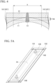
- the flow path 14 and the partial flow path 1411 included in the flow path mean a space through which a cooling liquid easily flows and which exhibits a substantial cooling effect. Therefore, as illustrated in FIG. 4 , the flow path 14 and the partial flow path 1411 are defined as spaces between the flow path upper lid 12 and the press forming member 11, the spaces having a thickness of 0.5 mm or more along a direction perpendicular to the flow path upper lid 12.
- the interval D between the partial flow paths 1411 is an interval between spaces defined above.
- the interval D between the partial flow paths 1411 is the total length of the laser weld 13, the width of the region where the flow path upper lid 12 and the press forming member 11 are in contact with each other, and the width of the region where the gap between the flow path upper lid 12 and the press forming member 11 is less than 0.5 mm.
- the width W of the partial flow path 1411 is the width of the space defined as described above. That is, the width W of the partial flow path 1411 is a width of a space having a thickness of 0.5 mm or more along a direction perpendicular to the flow path upper lid 12.
- the interval D between the partial flow paths 1411 and the width W of the partial flow path are values measured along a second direction perpendicular to the first direction which is the extending direction of the partial flow path 1141.
- a joint portion for forming the flow path 14 is the laser weld 13.
- the bead width can be reduced. Therefore, it is effective joining means for narrowing the interval D between the partial flow paths 1411.
- the laser welding forms a linear bead, it is possible to enhance the liquid tightness of the flow path 14 as compared with a point joining means such as spot welding.
- the configuration of the laser weld 13 is not particularly limited, and various configurations corresponding to the shape of the flow path 14 can be adopted. Hereinafter, a preferred aspect of the laser weld 13 will be described.
- the bead width on the laser radiation side that is, the wider one of the bead width of the surface of the laser weld 13 in the flow path upper lid 12 and the bead width of the surface of the laser weld 13 in the press forming member 11, may be set to 0.8 to 1.5 mm.
- the bead width By setting the bead width to 0.8 mm or more, the liquid tightness of the flow path 14 can be further enhanced.
- the bead width to 1.5 mm or less, evaporation of plating in the vicinity of the bead can be prevented, and corrosion resistance of the cooling structure 1 can be further enhanced.
- the laser weld 13 may be formed so as to satisfy all of the following three requirements:
- the bead width according to the above-described requirement (1) strongly correlates with the amount of heat input during laser welding. It is assumed that when the bead width is too large, the heat input during laser welding is too large so that Al-based plating vanishes in a wide range surrounding the weld metal, thereby the melted Al-based plating does not move to the surface of the weld metal. On the other hand, when the bead width is too small, the press forming member 11 and the flow path upper lid 12 may not be sufficiently joined.
- the interval of the plated steel sheet according to the above-described requirement (3) is an interval between the press forming member and the flow path upper lid measured in the vicinity of the laser weld 13.
- the vicinity of the laser weld 13 is an area within 0.1 mm from the weld metal included in the laser weld 13.
- the interval between the press forming member and the flow path upper lid is substantially uniform and the interval can measured in any places included in the area.
- the variation of the interval between the plated steel sheets is small in the range, and the value measured in the range can be recognized as the interval between the plated steel sheets.
- the interval between the press forming member 11 and the flow path upper lid 12 in the vicinity of the laser weld 13 is preferably 0.2 mm or less, 0.1 mm or less, or 0.05 mm or less.
- the laser weld 13 includes a start position 131, an end position 132, and a middle portion 133 therebetween.
- the start position 131 of the laser weld 13 is a portion corresponding to a portion where the laser welding is started, and the end position 132 of the laser weld 13 is a portion corresponding to a portion where the laser welding is finished.
- the middle portion 133 tends to have less welding defects than the start position 131 and the end position 132, and thus have more excellent corrosion resistance and liquid tightness. Therefore, it is preferable that the flow path 14 is formed using the middle portion 133 of the laser weld 13 and is separated from the start position 131 and the end position 132. In other words, as illustrated in FIG. 5A , it is preferable that laser welding is performed such that the middle portion 133 of the laser weld 13 is disposed between the start position 131 and the end position 132 of the laser weld 13 and the flow path 14. This makes it possible to prevent the start position 131 and the end position 132 from being exposed to the cooling liquid.
- start position 131 and end position 132 of the laser weld 13 are omitted from the cooling structure 1.
- a tab plate T is provided on the flow path upper lid 12 or the press forming member 11 before being laser welded, laser welding is performed so that the start position 131 and the end position 132 are formed on the tab plate T, and then the tab plate T is cut and removed, whereby the cooling structure 1 not including the start position 131 and the end position 132 of the laser weld 13 can be obtained.
- a configuration in which the start position 131 and the end position 132 are omitted only at a portion where liquid leakage is concerned may be applied.
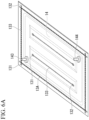
- the cooling structure 1 illustrated in FIGS. 6A and 6B when flow path upper lid 12 is peeled off from press forming member 11 at a portion (dark color portion denoted by reference numeral 13A) provided along the outer edge of press forming member 11 and flow path upper lid 12 in laser weld 13, the cooling liquid leaks to the outside of the cooling structure 1.
- the cooling structure 1 illustrated in FIG. 6A is obtained by manufacturing the flow path outer edge weld 13A using only the middle portion 133 of the laser weld 13. In this case, the start position and the end position are omitted from the flow path outer edge weld 13A, but are left in the cooling structure 1.
- the cooling structure 1 illustrated in FIG. 6B is obtained by providing the tab plate T on the flow path upper lid 12 or the press forming member 11 before being laser welded, performing laser welding so that the start position 131 and the end position 132 are formed on the tab plate T, and then cutting and removing the tab plate T.
- the start position and the end position generated at the time of forming the flow path outer edge weld 13A do not remain in the cooling structure 1.
- laser welding is performed, laser radiation is performed to a position in which the flow path upper lid 12 and the press forming member 11 are not exposed to the laser to run through, and laser radiation is then stopped, the start position and the end position in the formation of the flow path outer edge weld 13A do not remain in the cooling structure 1.
- a bead height of the laser weld 13 may be 0.3 mm or less.
- a gap between the flow path upper lid 12 and a cooling target for example, a battery pack or a battery cell
- the bead height of the laser weld 13 may be reduced, for example, through control of laser welding conditions.
- the bead height may be reduced by grinding the bead after the end of the laser welding.
- the flow path connecting portion 142 that communicates the plurality of partial flow paths 1411 may be further provided in the flow path 14.
- the cooling liquid inlet 143 and the cooling liquid outlet 144 for introducing a cooling liquid into the flow path may be further provided in the flow path 14.
- the flow path 14 forms one space.
- one cooling liquid inlet 143 and one cooling liquid outlet 144 may be provided in the cooling structure 1.
- the flow path connecting portion 142 may not be provided in the cooling structure 1.
- the cooling liquid inlet 143 and the cooling liquid outlet 144 may be provided in each of the plurality of partial flow paths 1411. Only a part of the plurality of partial flow paths 1411 may be communicated by the flow path connecting portion 142, and the flow path 14 may form two or more spaces.
- each of the two flow path connecting portions 142 is one straight flow path, and the flow path connecting portion 142 communicates with all the partial flow paths 1411 to be orthogonal thereto.
- the shape of the flow path connecting portion 142 and the arrangement of the flow path connecting portion 142 and the partial flow path 1411 are not limited thereto.
- the angle formed by the flow path connecting portion 142 and the partial flow path 1141 is not limited to 90°, and can be appropriately selected according to the use of the cooling structure 1.
- the flow path connecting portion 142 may have a branch structure. As shown in FIG.
- each of the two flow path connecting portions 142 may be branched in a fan shape starting from the cooling liquid inlet 143 or the cooling liquid outlet 144, and communicate with each of the partial flow paths 1411 at various angles at the branch destination.
- the laser weld 13 is omitted.
- the press forming member 11 and the flow path upper lid 12 30% or more of the surface of the laser weld 13 may be covered with the Al-based plating. Thereby, the cooling liquid corrosion resistance of the laser weld 13 is enhanced so that the cooling liquid corrosion resistance of the cooling structure 1 is further enhanced.
- the cover ratio of the Al-based plating with respect to the laser weld 13 is measured in accordance with the following procedures.
- any one of the partial flow paths 1411 included in the cooling structure is cut in a direction perpendicular to the first direction, i.e. perpendicular to the extending direction of the partial flow path 1411.
- the position which is cut is three points in total, including a middle point between the both ends of the partial flow path 1411, and two middle points between said middle point and the end portion of the partial flow path 1411.
- the both ends of the partial flow path 1411 are positions at which the partial flow path 1411 and the flow path connecting portion 142 join, and when the flow path connecting portion 142 is not included in the cooling structure 1, the both ends of the partial flow path 1411 are positions at which the cooling liquid inlet 143 and the cooling liquid outlet 144 are provided.
- the cover ratio in each cross sections is measured in which length a of the surface of the weld metal forming the laser weld 13 in the cross section is a denominator and a total of the length b along to the surface of the weld metal of the Al-based plating adhering on the surface of the weld metal is a numerator.
- the average of the cover ratio in three cross sections are calculated, and recognized as the cover ratio of the Al-based plating with respect to the laser weld 13.
- Laser weld is a joining method forming a weld metal which is uniform along with the weld direction. Therefore, the cover ratio in entire cooling structure 1 can be estimated based on the value obtained by the above-described method.
- the symbol 17 indicates the base steel sheet and the symbol 16 indicates the Al-based plating.
- the shape in a plane view of the press forming member 11 and the flow path upper lid 12 forming the cooling surface of the cooling structure 1 is not particularly limited.
- the plane view shape of the flow path upper lid 12 is desirably rectangular.
- the size of the flow path upper lid 12 in a plane view is preferably 1000 mm to 2300 mm in the longitudinal direction and 200 mm to 1500 mm in the lateral direction.
- the size of the press forming member 11 in a plane view is preferably 1000 mm to 2300 mm in the longitudinal direction and 200 mm to 1500 mm in the lateral direction.
- the size of the flow path upper lid 12 in the longitudinal direction in a plane view may be 1200 mm or more, 1400 mm or more, or 1600 mm or more.
- the size of the flow path upper lid 12 in the longitudinal direction in a plane view may be 2200 mm or less, 2000 mm or less, or 1800 mm or less.
- the size of the flow path upper lid 12 in the lateral direction in a plane view may be 250 mm or more, 500 mm or more, or 700 mm or more.
- the size of the flow path upper lid 12 in the lateral direction in a plane view may be 1400 mm or less, 1300 mm or less, or 1200 mm or less.
- the size of the press forming member 11 in the longitudinal direction in a plane view may be 1200 mm or more, 1400 mm or more, or 1600 mm or more.
- the size of the press forming member 11 in the longitudinal direction in a plane view may be 2200 mm or less, 2000 mm or less, or 1800 mm or less.
- the size of the press forming member 11 in the lateral direction in a plane view may be 250 mm or more, 500 mm or more, or 700 mm or more.
- the size of the press forming member 11 in the lateral direction in a plane view may be 1400 mm or less, 1300 mm or less, or 1200 mm or less.
- the outer surface corrosion resistance and the cooling liquid corrosion resistance can be enhanced by using the Al-based plated steel sheets as the press forming member 11 and the flow path upper lid 12. As a result, it is possible to suppress flow path corrosion and to suppress occurrence of contamination that causes a decrease in thermal conductivity and clogging.
- the interval D between the partial flow paths 1411 in the parallel flow path portion 141 is set to 20 mm or less, and the area where the cooling liquid and the flow path upper lid 12 are in contact with each other is increased, so that the cooling efficiency can be improved.
- the press forming member 11 and the flow path upper lid 12 are laser welded, whereby the liquid tightness of the flow path 14 can be enhanced.
- the battery unit 2 according to the present embodiment includes a battery cell 21, a battery pack 22 in which the battery cell 21 is housed, and the cooling structure 1 according to the first embodiment.
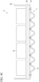
- the battery pack 22 can be used as the flow path upper lid 12 of the cooling structure 1.
- the bank part 112 of the press forming member 11 and the battery pack 22 can be laser welded.
- the battery unit 2 may be manufactured by joining the flow path upper lid 12 and the battery pack 22.
- a gap filler 23 may be disposed between the flow path upper lid 12 and the battery pack 22.
- the gap filler 23 is generally a resin containing a pigment having high thermal conductivity.
- the thermal conductivity of the gap filler 23 is preferably 3.5 W/m or more.
- An example of the gap filler 23 is "SDP-3540-A" manufactured by Shin-Etsu Chemical Co., Ltd.
- the thickness of the gap filler is preferably 0.1 mm to 8.0 mm, and more preferably 0.5 mm to 3.0 mm.
- the configuration of the battery pack 22 is not particularly limited.
- the battery pack 22 may have a substantially rectangular shape, and the cooling structure 1 may be disposed on the bottom surface portion thereof, or the bottom surface portion thereof may be used as the flow path upper lid 12 of the cooling structure 1.
- the steel sheet forming the battery pack 22 is preferably an Al-based plated steel sheet or a Zn-based plated steel sheet.
- the thickness of the Al-based plated steel sheet forming the bottom surface portion of the battery pack 22 is not particularly limited, but is, for example, preferably 0.2 to 1.2 mm or 0.3 to 1.2 mm, and more preferably 0.4 to 0.6 mm.
- the bottom surface portion can be formed thin while maintaining a strength of the bottom surface portion of the battery pack 22. Therefore, since a distance between a cooling liquid and an internal structure of the battery pack 22 can be narrowed, cooling efficiency of the battery pack 22 can be enhanced, and cooling responsiveness of the battery pack 22 can be enhanced.
- the manufacturing method of the cooling structure according to the third embodiment includes press-forming (S1) a plated steel sheet to obtain a press forming member 11, and laser welding (S2) the press forming member and the flow path upper lid. Details of these steps will be described below.
- the cooling structure according to the first embodiment can be suitably manufactured.
- the following description does not limit the manufacturing method of the cooling structure according to the first embodiment.
- the press forming member 11 having the groove part 111 and the bank part 112 provided around the groove part 111 is obtained.
- a plated steel sheet subjected to press forming includes a Al-based plating.
- a preferred aspect of the plated steel sheet is as described above.
- the flow path 14 includes the parallel flow path portion 141 in which the plurality of partial flow paths 1411 extending along the first direction are arranged in the second direction orthogonal to the first direction, and in the parallel flow path portion 141, the interval D between the adjacent partial flow paths 1411 is 20 mm or less. In order to achieve such a shape of the flow path 14, it is necessary to form the groove part 111 in press forming.
- the flow path upper lid 12 which is a flat sheet, is placed on a position covering the groove part 111 of the press forming member 11, and the flow path upper lid 12 and the bank part 112 of the press forming member 11 are laser welded. As a result, the laser weld 13 forming the flow path 14 through which the cooling liquid is capable of flowing is obtained.
- the laser welding conditions are not particularly limited, and suitable conditions according to the sheet thickness of the plated steel sheet and the like can be appropriately adopted. Examples of further preferred laser welding conditions are as follows. When the film thickness of the Al-based plating is 10.0 ⁇ m or more and the interval between the press forming member 11 and the flow path upper lid 12 in the vicinity of the laser weld is 0.3 mm or less, it is preferable that a beam diameter is set to 0.2 to 0.8 mm and a heat input per unit welding length is set to 30 to 120 kJ/m.
- the beam diameter is 0.4 to 0.6 mm and the heat input per unit welding length is set to 30 to 60 kJ/m.
- the Al-based plated steel sheet was press-formed to prepare a press forming member.
- the press forming member and a flow path upper lid formed of the flat sheet of the Al-based plated steel sheet were laser welded to produce a cooling structure.
- the flow path width and the flow path interval of the plurality of partial flow paths extending in parallel are shown in Table 1.
- the manufacture conditions not included in Table 1 were as follows. The flow path connecting portion communicating the partial flow paths was not created.
- FIG. 9 is a schematic diagram of a part of the manufactured cooling structure. For convenience, only two partial flow paths are illustrated in FIG. 9 , but actually, the number of partial flow paths capable of covering a battery having a width of 120 mm is provided in the cooling structure. In any of the examples shown in Table, the cooling structure could be assembled by laser welding.
- D/2 is a value obtained by dividing the interval D between the plurality of partial flow paths by 2. This value is the maximum distance along the flow path width direction at a location where the partial flow path and the partial flow path are not in direct contact with each other, and is preferably as small as possible. If the D/2 is too large, cooling of a portion not in contact with the flow path becomes insufficient, and there is a possibility that a sufficient function as a cooling structure cannot be exhibited.
- a sample having a D/2 of 7.5 mm or less was rated as "A”
- a sample having a D/2 of more than 7.5 mm and 10 mm or less was rated as "B”
- a sample having a D/2 of more than 10 mm was rated as "C”.
- a sample evaluated as Rank A or Rank B was determined to have a sufficiently narrow flow path interval.
- [Table 1] Flow path width W (mm) Flow path interval D (mm) D/2 (mm) Flow path width determination D/2 determination 60 25 12.5 B c 60 20 10.0 B B 60 15 7.5 B A 60 10 5.0 B A 60 5 2.5 B A 30 25 12.5 A c 30 20 10.0 A B 30 15 7.5 A A 30 10 5.0 A A 30 5 2.5 A A 20 25 12.5 S c 20 20 10.0 S B 20 15 7.5 S A 20 10 5.0 S A 20 5 2.5 S A 10 25 12.5 S c 10 20 10.0 S B 10 15 7.5 S A 10 10 5.0 S A 10 5 2.5 S A 10 5.0 S A 10 5 2.5 S A 10 25 12.5 S c 10 20 10.0 S B 10 15 7.5 S A 10 10 5.0 S A 10 5 2.5 S A
- cover ratio the ratio of the area of the Al-based plating covering the laser weld with respect to the surface area of the laser weld.
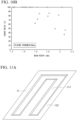
- FIG. 10A A relationship between the bead width and the cover ratio in a cooling structure manufactured from the steel sheet of which the film thickness of the plating was 10 ⁇ m is shown in FIG. 10A .
- FIG. 10A A relationship between the bead width and the cover ratio in a cooling structure manufactured from the steel sheet of which the film thickness of the plating was 60 ⁇ m is shown in FIG. 10A .
- the bead width was 1.5 mm or less
- the entire surface of the laser weld was covered with the Al-based plating. It is assumed that these examples have high inner surface corrosion resistance.
- the bead width was more than 1.5 mm, a trend was confirmed that the broader the bead width was, the smaller the cover ratio was.
- the shapes of the press forming member and the flow path upper lid before welding were as shown in FIGS. 11A and 11B , and the shape of the flow path was as illustrated in FIG. 11C .
- the cross-sectional shape of the partial flow path is the waveform shown in FIG. 3 , but the same shape as other examples was adopted except for this.
- the flow path shape in a plane view is a U shape, and two flow paths extending in the longitudinal direction correspond to the partial flow path.
- the flow path width was 20 mm in all cooling structures.
- the bead width of the manufactured cooling structures was measured and described in Table 3.
- the bead width described in Table 3 is the width of the wider one of the bead of the laser weld in the flow path upper lid and the bead of the laser weld in the press forming member.
- LLC long-life coolant
Landscapes
- Engineering & Computer Science (AREA)
- Chemical & Material Sciences (AREA)
- Electrochemistry (AREA)
- General Chemical & Material Sciences (AREA)
- Chemical Kinetics & Catalysis (AREA)
- Manufacturing & Machinery (AREA)
- Physics & Mathematics (AREA)
- Optics & Photonics (AREA)
- Mechanical Engineering (AREA)
- Plasma & Fusion (AREA)
- Algebra (AREA)
- General Physics & Mathematics (AREA)
- Mathematical Analysis (AREA)
- Mathematical Optimization (AREA)
- Pure & Applied Mathematics (AREA)
- Inorganic Chemistry (AREA)
- Sealing Battery Cases Or Jackets (AREA)
- Laser Beam Processing (AREA)
- Cooling Or The Like Of Electrical Apparatus (AREA)
Abstract
Description
- The present invention relates to a cooling structure, a battery unit, and a manufacturing method of the cooling structure.
- The present application claims priority based on
Japanese Patent Application No. 2021-085188 filed in Japan on May 20, 2021 - In order to reduce the amount of carbon dioxide emissions, with respect to automobiles, electric vehicles (EV) are being developed. In a battery box of an EV, it is necessary to provide a cooling structure in order to prevent deterioration of a battery due to a temperature rise. Hitherto, air-cooling types have been the mainstream for a cooling structure, but in recent years, with the increase in capacities of batteries, water-cooling types having a high cooling capacity have increasingly been adopted (for example,
Patent Documents -
- [Patent Document 1]
Japanese Unexamined Patent Application, First Publication No. 2020-107443 - [Patent Document 2]
Japanese Patent No. 6125624 - [Patent Document 3]
Japanese Unexamined Patent Application, First Publication No. 2012-17954 - The outer wall portion and the cooling structure of the water-cooling type battery pack are often made of aluminum having high corrosion resistance to a cooling liquid. However, aluminum has a problem in terms of cost. In addition, since aluminum is soft, it is difficult to reduce the weight of the outer wall by thinning the outer wall while securing the outer wall strength in a cooling structure formed of an aluminum plate. When the material of these members is a steel sheet, it is possible to provide a water-cooling type battery pack at low cost and reduce the weight thereof.
- A long-life coolant (LLC) aqueous solution containing an organic component flows as a cooling liquid in the water-cooling medium flow path. Therefore, the member water-cooling medium flow path is required to have high corrosion resistance against a cooling liquid. In addition, since the battery pack and the cooling structure are disposed on the bottom surface of the automobile, the battery pack and the cooling structure are exposed to an external environment. Therefore, the members constituting the battery pack and the cooling structure are required to have a corrosion resistance equivalent to that of the suspension parts of the automobile. Hereinafter, corrosion resistance to a cooling liquid is referred to as cooling liquid corrosion resistance or inner surface corrosion resistance, and corrosion resistance to an external environment is referred to as outer surface corrosion resistance. In addition, when "corrosion resistance", is simply referred to, this refers to both cooling liquid corrosion resistance and outer surface corrosion resistance.
- Plating is one of means for enhancing corrosion resistance of a steel sheet. For example, by forming plating such as Al-based plating on the surface of the steel sheet, both cooling liquid corrosion resistance and outer surface corrosion resistance can be enhanced.
- On the other hand, as a matter of course, the cooling structure is required to have high cooling efficiency. In addition, liquid tightness of the flow path is also required to maintain cooling efficiency and suppress LLC leakage. However, as of yet, there have been almost no examples of a cooling structure in which a flow path is formed using a plated steel sheet, and therefore, a method for joining plated steel sheets has not been studied. Spot welding is usually used as means for firmly joining plated steel sheets. However, since spot welding is point joining, it is difficult to ensure liquid tightness of the flow path. Although it is possible to secure the liquid tightness of the spot weld using a sealer, the sealer may be deteriorated by the LLC. Therefore, in manufacturing the cooling structure, a joining method capable of securing liquid tightness of the flow path while maintaining corrosion resistance is also required.
- In the technique of Patent Document 3, a cooler is manufactured by brazing an aluminum-plated steel sheet. However, the technique of Patent Document 3 is assumed to be applied only to a small device, and it is difficult to cope with coolers of various sizes. Further, in Patent Document 3, it is a problem to prevent deformation of the exterior member, and it is difficult to change joining means of the exterior member.
- In view of the above circumstances, an object of the present invention is to provide a cooling structure having high cooling efficiency, excellent liquid tightness of a flow path, and further having high cooling liquid corrosion resistance and outer surface corrosion resistance, a battery unit, and a manufacturing method of the cooling structure.
- The gist of the present invention is as follows.
-
- (1) A cooling structure according to an aspect of the present invention includes a press forming member having a groove part and a bank part provided around the groove part, a flow path upper lid which is a flat sheet overlapped at a position covering the groove part of the press forming member and forms a flat cooling surface, and a laser weld which joins opposing surfaces of the flow path upper lid and the bank part to form a flow path through which a cooling liquid is capable of flowing, in which the press forming member and the flow path upper lid are plated steel sheets each including a base steel sheet and a Al-based plating, the flow path includes a parallel flow path portion in which a plurality of partial flow paths extending along a first direction are arranged in a second direction orthogonal to the first direction, and in a part or all of the parallel flow path portions, an interval between the adjacent partial flow paths is 20 mm or less.
- (2) In the cooling structure described in (1) above, in the parallel flow path portion, an interval between the adjacent partial flow paths may be 0.8 to 15 mm.
- (3) In the cooling structure described in (1) of (2) above, the width of the partial flow path may be 6 to 60 mm.
- (4) In the cooling structure described in (1) or (2) above, the width of the partial flow path may be 6 to 20 mm.
- (5) In the cooling structure described in any one of (1) to (4) above, the Al-based plating may include Si.
- (6) In the cooling structure described in (5) above, the Si content of the Al-based plating may be 2.0 to 15 mass%.
- (7). In the cooling structure described in any one of (1) to (6) above, the cooling structure may include a chemical conversion coating film including 50 mass% or more of a Zr-based component, a Ti-based component or a Si-based component.
- (8) In the cooling structure described in any one of (1) to (7) above, a cross-sectional shape of the bank part may be substantially an arc, and the radius of curvature of the bank part at a contact section between the flow path upper lid and the bank part may be 15 mm or less.
- (9) In the cooling structure described in any one of (1) to (8) above, a film thickness of the Al-based plating may be 10.0 µm or more, in a vicinity of the laser weld, an interval between the press forming member and the flow path upper lid may be 0.3 mm or less, and a wider one of a bead width of a surface of the laser weld in the flow path upper lid and a bead width of a surface of the laser weld in the press forming member may be 0.8 to 1.5 mm.
- (10) In the cooling structure described in any one of (1) to (9) above, the plated steel sheet forming the press forming member and the flow path upper lid may have a sheet thickness of 0.3 to 1.2 mm.
- (11) In the cooling structure described in any one of (1) to (10) above, the laser weld may include a flow path outer edge weld surrounding all the flow paths, and a starting end and a terminating end of the laser weld may be excluded from the flow path outer edge weld.
- (12) In the cooling structure described in any one of (1) to (11) above, a start position and an end position of the laser weld may be omitted from the cooling structure.
- (13) In the cooling structure described in any one of (1) to (12) above, a part or a whole of a surface of the laser weld between the press forming member and the flow path upper lid may be covered with the Al-based plating.
- (14) In the cooling structure described in any one of (1) to (13) above, 30% or more of a surface of the laser weld between the press forming member and the flow path upper lid may be covered with the Al-based plating.
- (15) In the cooling structure described in any one of (1) to (14) above, the bead height of the laser weld in the flow path upper lid may be 0.3 mm or less.
- (16) A battery unit according to another aspect of the present invention includes a battery cell, a battery pack in which the battery cell is housed, and the cooling structure described in any one of (1) to (15) above, in which the flow path upper lid of the cooling structure is joined to the battery pack.
- (17) A battery unit according to another aspect of the present invention includes a battery cell, a battery pack in which the battery cell is housed, and the cooling structure described in any one of (1) to (15) above, in which the flow path upper lid of the cooling structure is the battery pack.
- (18) A manufacturing method of a cooling structure according to another aspect of the present invention includes press-forming a steel sheet to obtain a press forming member having a groove part and a bank part provided around the groove part, and overlapping a flow path upper lid which is a flat sheet at a position covering the groove part of the press forming member and laser welding the flow path upper lid and the bank part of the press forming member to obtain a laser weld which forms a flow path through which a cooling liquid is capable of flowing, in which the press forming member and the flow path upper lid are plated steel sheets each including a base steel sheet and an Al-based plating, the flow path includes a parallel flow path portion in which a plurality of partial flow paths extending along a first direction are arranged in a second direction orthogonal to the first direction, and in the parallel flow path portions, an interval between the adjacent partial flow paths is 20 mm or less.
- (19) In the manufacturing method of a cooling structure described in (18) above, a film thickness of the Al-based plating is 10.0 µm or more, in the laser welding, a beam diameter may be 0.2 to 0.8 mm and a heat input per unit welding length may be 30 to 120 kJ/m, and an interval between the press forming member and the flow path upper lid in the vicinity of the laser weld may be 0.3 mm or less.
- According to the present invention, it is possible to provide a cooling structure having high cooling efficiency, excellent liquid tightness of a flow path, and further having high cooling liquid corrosion resistance and outer surface corrosion resistance, a battery unit, and a manufacturing method of the cooling structure.
-
-
FIG. 1 is a cross-sectional view perpendicular to an extending direction of a partial flow path of a cooling structure in which a cross-sectional shape of a press forming member is rectangular. -
FIG. 2A is a plane view of the cooling structure in which a flow path connecting portion and a partial flow path are orthogonal to each other as viewed from a press forming member side. -
FIG. 2B is a plane view of the cooling structure in which a flow path connecting portion has a branch structure as viewed from a press forming member side. -
FIG. 3 is a cross-sectional view perpendicular to the extending direction of the partial flow path of the cooling structure in which the cross-sectional shape of the press forming member is corrugated. -
FIG. 4 is an enlarged cross-sectional view of the cooling structure showing an interval D between partial flow paths. -
FIG. 5A is a perspective view of a cooling structure in which a middle portion of a laser weld is disposed between a flow path and a start position and an end position of the laser weld. -
FIG. 5B is a perspective view of the cooling structure in which the start position and the end position of the laser weld are omitted. -
FIG. 6A is a schematic view of a cooling structure in which the start position and the end position of the laser weld are omitted from a flow path outer edge weld. -
FIG. 6B is a schematic view of a cooling structure in which the start position and the end position of the laser weld are omitted from the flow path outer edge weld. -
FIG. 7 is a schematic view of a method for measuring a cover ratio in a surface of the laser weld between the press forming member and the flow path upper lid. -
FIG. 8A is a perspective view of a battery unit. -
FIG. 8B is a cross-sectional view of a battery unit using a battery pack as a flow path upper lid. -
FIG. 8C is a cross-sectional view of the battery unit in which the battery pack and the flow path upper lid are joined. -
FIG. 9 is a perspective view of a cooling structure of Example 1. -
FIG. 10A is a graph showing a relationship between a bead width and a cover ratio in a cooling structure of Example 2 manufactured from a steel sheet of which the film thickness of a plating is 10 µm. -
FIG. 10B is a graph showing a relationship between a bead width and a cover ratio in a cooling structure of Example 2 manufactured from a steel sheet of which the film thickness of a plating is 60 µm. -
FIG. 11A is a perspective view of a press forming member before laser welding of a cooling structure of Example 3. -
FIG. 11B is a perspective view of the flow path upper lid before laser welding of the cooling structure of Example 3. -
FIG. 11C is a perspective view of the cooling structure of Example 3. - Hereinafter, preferred embodiments of the present invention will be described in detail with reference to the accompanying drawings.
- First, a cooling structure according to a first embodiment of the present invention will be described. As illustrated in
FIGS. 1 and 2A , acooling structure 1 according to the present embodiment includes apress forming member 11, a flow pathupper lid 12, and alaser weld 13 that joins these components. The laser weld is a joint portion formed of a linear bead (that is, a weld metal).FIG. 1 is a cross-sectional view of thecooling structure 1, andFIG. 2A is a plane view of thecooling structure 1 from thepress forming member 11 side. - The
press forming member 11 is a member obtained by press forming a plated steel sheet, and includes agroove part 111 and abank part 112 provided around thegroove part 111. InFIG. 1 , the bottom of thepress forming member 11 and the periphery thereof aregroove parts 111, and the top portion of thepress forming member 11 and the periphery thereof arebank parts 112. The flow pathupper lid 12 is a member forming a flat cooling surface, has a flat sheet shape, and is overlapped at a position covering thegroove part 111 of thepress forming member 11. - The
press forming member 11 and the flow pathupper lid 12 are joined by alaser weld 13. Specifically, thelaser weld 13 joins opposing surfaces of the flow pathupper lid 12 and thebank part 112 of thepress forming member 11. As a result, the flow pathupper lid 12 and thegroove part 111 form aflow path 14 through which the cooling liquid is capable of flowing. As indicated by a broken line inFIG. 2A , in theflow path 14, any cooling liquid such as LLC introduced from a coolingliquid inlet 143 can flow to a coolingliquid outlet 144. Accordingly, it is possible to cool the flow pathupper lid 12 as a cooling surface and an arbitrary object in contact with the flow pathupper lid 12. In the flow path illustrated inFIG. 2A , the plurality ofpartial flow paths 1411 extending along the first direction includes a parallelflow path portion 141 arranged in the second direction orthogonal to the first direction, and a flowpath connecting portion 142 that communicates thesepartial flow paths 1411. The first direction is, for example, a longitudinal direction or a lateral direction of thecooling structure 1. A specific configuration of theflow path 14 will be described later. - Shapes of the
bank part 112 and thegroove part 111 are not particularly limited. In thepress forming member 11 illustrated inFIG. 1 , the cross sections of thebank part 112 and thegroove part 111 are substantially rectangular (trapezoidal). On the other hand, the cross-sectional shape of one or both of thebank part 112 and thegroove part 111 of thepress forming member 11 may be a partially circular shape or a substantially circular arc shape. As illustrated inFIG. 3 , thepress forming member 11 in which the cross-sectional shapes of both thebank part 112 and thegroove part 111 are partially circular or substantially arc is referred to as a corrugated plate. - In a case where the cross-sectional shape of the
bank part 112 is substantially an arc, the radius of curvature of thebank part 112 at the contact section between the flow pathupper lid 12 and thebank part 112, that is, at thelaser weld 13 may be 15 mm or less, 13 mm or less, or 10 mm or less. As the radius of curvature of thebank part 112 in thelaser weld 13 is smaller, the width W of thepartial flow path 1411 is widened, and the cooling efficiency of thecooling structure 1 is further enhanced. - The radius of curvature of the
bank part 112 at the contact section between the flow pathupper lid 12 and thebank part 112 is measured in a cross section of thepartial flow path 1411 parallel to the second direction orthogonal to the first direction that is the extending direction of thepartial flow path 1411 and perpendicular to the surface of the flow pathupper lid 12. As illustrated inFIG. 3 , in this cross section, the radius of a circle R including a total of three points including the center of the weld metal and twopoints 1 mm away from the center of the weld metal along the second direction at the center of thebank part 112 in the sheet thickness direction is the radius of curvature of thebank part 112 at the contact section between the flow pathupper lid 12 and thebank part 112. - The
press forming member 11 and the flow pathupper lid 12 are plated steel sheets having a base steel sheet and Al plating provided on the surface of the base steel sheet. The configuration of the Al plated steel sheet is not particularly limited, but a preferred configuration is as follows. - The sheet thickness of the plated steel sheet forming the
press forming member 11 and the flow pathupper lid 12 may be 0.3 mm or more. By setting the sheet thickness to 0.3 mm or more, the press formability and the rigidity of thecooling structure 1 can be further improved. The sheet thickness of the plated steel sheet forming thepress forming member 11 and the flow pathupper lid 12 may be 0.4 mm or more, 0.6 mm or more, or 0.8 mm or more. On the other hand, the sheet thickness of the plated steel sheet forming thepress forming member 11 and the flow pathupper lid 12 may be 1.2 mm or less. By setting the sheet thickness of thepress forming member 11 to 1.2 mm or less, it is easier to bring thepress forming member 11 into close contact with the flow pathupper lid 12, and the liquid tightness of the flow path is further improved. By setting the sheet thickness of the flow pathupper lid 12 to 1.2 mm or less, the cooling efficiency of thecooling structure 1 can be further improved. The sheet thicknesses of thepress forming member 11 and the flow pathupper lid 12 may be 1.1 mm or less, 1.0 mm or less, or 0.8 mm or less. Thepress forming member 11 and the flow pathupper lid 12 may have different sheet thicknesses. Since the cooling efficiency increases as the sheet thickness decreases, it is preferable that the flow pathupper lid 12 is thin. - The base steel sheet of the plated steel sheet forming the
press forming member 11 and the flow pathupper lid 12 is not particularly limited. For example, in order to further increase the rigidity of thecooling structure 1, the base steel sheet of the flow pathupper lid 12 may be a high strength steel sheet having a tensile strength of 980 MPa or more. On the other hand, in order to further enhance the press formability, the base steel sheet of thepress forming member 11 may be a soft steel sheet having a tensile strength of about 270 MPa, for example, SPCC. Various forms according to the shape and application of thecooling structure 1 can be applied to the base steel sheet forming thepress forming member 11 and the flow pathupper lid 12. Examples of the base steel sheet include IF steel to which Ti, Nb, B, or the like is added, Al-k steel, Cr-added steel, stainless steel, high tensile strength steel sheets, low-carbon steel, medium-carbon steel, high-carbon steel, alloy steel, and the like. - The Al-based plating of the plated steel sheet forming the
press forming member 11 and the flow pathupper lid 12 is, for example, two-component or multicomponent plating in which the Al content is 70 mass% or more. It is preferable that the Al-based plating is two-component or multicomponent plating in which Al content is 70 to 98 mass% and Si content is 2.0 to 15 mass%. Si content of the Al-based plating may be 3.0 mass% or more, 4.0 mass% or more, or 5.0 mass% or more. Si content of the Al-based plating may be 14 mass% or less, 12 mass% or less, or 10 mass% or less. By setting the Si content to be within the above range, the workability and corrosion resistance of the Al-based plated steel sheet can be extremely enhanced. As impurity elements in the plating layer, a trace amount of Fe, Ni, Co, or the like may be interposed. In addition, if necessary, Mg, Sn, mischmetal, Sb, Zn, Cr, W, V, Mo, and the like may be contained in the Al-based plating. - The manufacturing method of the Al-based plated steel sheet is not particularly limited. For example, the Al-based plating can be provided by hot-dip plating by a sendzimir method, an all-radiant method, or the like, melt flux plating, electro plating, or vapor deposition plating.
- The film thickness of the Al-based plating is not particularly limited. For example, the film thickness of the Al-based plating may be 10 µm or more, 12 µm or more, 15 µm or more, or 20 µm or more. The film thickness of the Al-based plating may be 60 µm or less, 50 µm or less, or 40 µm or less. The larger the film thickness of the Al-based plating is, the higher the inner surface corrosion resistance of the
cooling structure 1 is. In addition, as described later, Al can be provided on a surface of the weld metal in thelaser weld 13 by setting the film thickness of the Al-based plating, the conditions of laser welding, and the interval between the press forming member and the flow path upper lid within a prescribed range. - In order to further enhance external corrosion resistance and cooling liquid corrosion resistance of the Al-based plated steel sheet or the like, it is preferable that chemical conversion treatment is performed on the surface of the Al-based plated steel sheet or the like. As the chemical conversion treatment, generally known chemical conversion treatment can be used. A chemical conversion coating film containing one or more selected from the group including a Zr-based component, a Ti-based component and a Si-based component as a main component (for example, 50 mass% or more in terms of mass%) is preferably formed. In a case in which the chemical conversion coating film includes two or more of the Zr-based component, the Ti-based component and the Si-based component, a total content of the components may be 50 mass% or more. The chemical conversion coating film may contain an organic component. Hereinafter, the "main component" of the chemical conversion coating film means a component having a proportion of 50 mass% or more in the chemical conversion coating film.
- Examples of the chemical conversion coating film include those listed in
Japanese Unexamined Patent Application, First Publication No. 2008-115442 Japanese Unexamined Patent Application, First Publication No. 2013-7108 Japanese Unexamined Patent Application, First Publication No. 2004-232040 Japanese Patent Publication No. 3302676 Japanese Patent Publication No. 4776458 Japanese Patent Publication No. 5336002 - A first example of the chemical conversion coating film is an example of a film containing a Zr-based component as a main component, and is composed of only Zr, F, P, C, O, N, and H, and does not contain an organic substance having a number average molecular weight of 200 or more. The components are adjusted so that, among the constituent elements of the chemical conversion coating film, a mass ratio Zr/F of Zr to F is 1.0 to 10.0 and a mass ratio Zr/P of Zr to P is 8.5 to 18.0, and a Zr content contained in the chemical conversion coating film is 23.0 mass% to 48.0 mass%. A source of each component of the chemical conversion coating film is composed of one or more inorganic acids selected from the group consisting of carbonic acid, phosphoric acid, and hydrofluoric acid and/or ammonium salts thereof, and a zirconium-containing complex compound excluding zirconium hydrofluoric acid.
- A second example of the chemical conversion coating film is an example of a film containing a Zr-based component as a main component, and contains (A) at least one or more among a titanium compound and a zirconium compound, (B) at least one or more among 2 to 6 bonded phosphate esters of myo-inositol, and alkali metal salts, alkaline earth metal salts, and ammonium salts thereof, and (C) silica. In this chemical conversion coating film, a mass ratio of (A) in terms of metal (Zr + Ti) : (B) : (C) is 1 : 0.2 to 1.7 : 0.2 to 5.
- Examples of the titanium compound include potassium titanium oxalate, titanyl sulfate, titanium chloride, titanium lactate, titanium isopropoxide, isopropyl titanate, titanium ethoxide, titanium 2-ethyl-1-hexanolate, tetraisopropyl titanate, tetra-n-butyl titanate, and titania sol.
- Examples of the zirconium compound include zirconyl nitrate, zirconyl acetate, zirconyl sulfate, zirconyl ammonium carbonate, potassium zirconium carbonate, sodium zirconium carbonate, and zirconium acetate.
- Examples of the 2 to 6 bonded phosphate esters of myo-inositol include myo-inositol diphosphate ester, myo-inositol triphosphate ester, myo-inositol tetraphosphate ester, myo-inositol pentane phosphate ester, and myo-inositol hexane phosphate ester.
- Examples of the silica include a water-dispersible silica compound. Examples of the water-dispersible silica compound include liquid-phase colloidal silica and gas-phase silica. The liquid-phase colloidal silica is not particularly limited, and examples thereof include SNOWTEX C, SNOWTEX O, SNOWTEX N, SNOWTEX S, SNOWTEX UP, SNOWTEX PS-M, SNOWTEX PS-L,
SNOWTEX 20,SNOWTEX 30, SNOWTEX 40 (registered trademark) (all manufactured by Nissan Chemical Industries, Ltd.), ADELITE AT-20N, ADELITE AT-20A, and ADELITE AT-20Q (all manufactured by Asahi Denka Kogyo K.K.). - The gas-phase silica is not particularly limited, and examples thereof include AEROSIL 50, AEROSIL 130, AEROSIL 200, AEROSIL 300, AEROSIL 380, AEROSIL TT600, AEROSIL MOX80, and AEROSIL MOX170 (all manufactured by NIPPON AEROSIL CO., LTD.).
- A third example of the chemical conversion coating film is an example of a film containing a Zr-based component as a main component, and is a composite film composed of a zirconium compound, a vanadium compound, a silica compound, a phosphoric acid compound, and an organic compound having at least one functional group among a hydroxyl group, a carbonyl group, and a carboxyl group. This chemical conversion coating film contains 2 to 1200 mg/m2 of zirconium, 0.1 to 300 mg/m2 of vanadium, and 0.3 to 450 mg/m2 of a phosphoric acid compound in terms of PO4 3- per one side of an Al-based plated steel sheet. Furthermore, in the chemical conversion coating film, a content of chromium or a chromium compound is 0.1 mg/m2 or less in terms of chromium, and a content of fluorine or a fluorine compound is 0.1 mg/m2 or less in terms of fluorine.
- Examples of the zirconium compound include zirconyl nitrate, zirconyl acetate, zirconyl sulfate, zirconyl ammonium carbonate, potassium zirconium carbonate, sodium zirconium carbonate, and zirconium acetate.
- Examples of the vanadium compound include vanadium pentoxide, metavanadic acid, ammonium metavanadate, sodium metavanadate, vanadium oxytrichloride, vanadium trioxide, vanadium dioxide, vanadium oxysulfate, vanadium oxyacetylacetonate, vanadium acetylacetonate, vanadium trichloride, phosphovanadomolybdic acid, vanadium sulfate, vanadium dichloride, and vanadium oxide.
- Examples of the silica compound include a water-dispersible silica compound. Examples of the water-dispersible silica compound include colloidal silica and gas-phase silica, and examples of the colloidal silica include, but are not particularly limited to, SNOWTEX C, SNOWTEX O, SNOWTEX N, SNOWTEX S, SNOWTEX UP, SNOWTEX PS-M, SNOWTEX PS-L,
SNOWTEX 20,SNOWTEX 30, SNOWTEX 40 (all manufactured by Nissan Chemical Industries, Ltd.), ADELITE AT-20N, ADELITE AT-20A, and ADELITE AT-20Q (all manufactured by Asahi Denka Kogyo K.K.). - The gas-phase silica is not particularly limited, and examples thereof include AEROSIL 50, AEROSIL 130, AEROSIL 200, AEROSIL 300, AEROSIL 380, AEROSIL TT600, AEROSIL MOX80, and AEROSIL MOX170 (all manufactured by NIPPON AEROSIL CO., LTD.).
- The phosphoric acid compound may contain a phosphate ion. As the phosphoric acid compound, for example, orthophosphoric acid (phosphoric acid), metaphosphoric acid, pyrophosphoric acid, and salts such as an ammonium salt, a sodium salt, a calcium salt, and a potassium salt in which some or all of hydrogen ions of these substances are replaced can be used alone or in combination.
- Examples of the organic compound having at least one functional group of a hydroxyl group, a carbonyl group, and a carboxyl group include alcohols such as methanol, ethanol, isopropanol, and ethylene glycol; carbonyl compounds such as formaldehyde, acetaldehyde, furfural, acetylacetone, ethyl acetoacetate, dipivaloylmethane, and 3-methylpentanedione; organic acids such as formic acid, acetic acid, propionic acid, tartaric acid, ascorbic acid, gluconic acid, citric acid, and malic acid; monosaccharides such as glucose, mannose, and galactose; oligosaccharides such as maltose and sucrose; natural polysaccharides such as starch and cellulose; aromatic compounds such as tannic acid, humic acid, lignin sulfonic acid, and polyphenol; and synthetic polymers such as polyvinyl alcohol, polyethylene glycol, polyacrylic acid, polyacrylamide, polyethyleneimine, and water-soluble nylon.
- The chemical conversion coating film may contain a lubricity-imparting component composed of at least one of a polyolefin-based wax and a paraffin-based wax as an additional component.
- A fourth example of the chemical conversion coating film is an example of a film containing a Ti-based component as a main component, and is a film in which an oxide or a hydroxide of a valve metal and a fluoride coexist. Examples of the valve metal include Ti and V. Among them, a tetravalent compound of Ti is a stable compound, and is preferable because a film having excellent characteristics can be formed. Examples of the film containing a Ti-based component as a main component include a film in which an oxide [TiO2], a hydroxide [Ti(OH)4], or the like is combined. In this film, a fluoride of Ti, for example, a fluoride such as XnTiF6 (X: alkali metal, alkaline earth metal, or NH4, n = 1 or 2) or TiF4 coexists.
- A fifth example of the chemical conversion coating film is an example of a film containing a Si-based component as a main component, and is a chemical conversion coating film containing an organosilicon compound (silane coupling agent) as a main component. The organosilicon compound is obtained by blending a silane coupling agent (A) containing one amino group in the molecule and a silane coupling agent (B) containing one glycidyl group in the molecule at a solid content mass ratio [(A)/(B)] of 0.5 to 1.7. The organosilicon compound contains, in the molecule, two or more functional groups (a) represented by the formula -SiR1R2R3 (wherein R1, R2, and R3 each independently represent an alkoxy group or a hydroxyl group, and at least one represents an alkoxy group) and one or more of at least one type of hydrophilic functional groups (b) selected from a hydroxyl group (which is separate from those that can be contained in the functional group (a)) and an amino group, and has an average molecular weight of 1000 to 10000.
- A sixth example of the chemical conversion coating film is an example of a film containing a Si-based component as a main component, and is a chemical conversion coating film containing an organosilicon compound (silane coupling agent) as a main component. The organosilicon compound has a cyclic siloxane structure in its structure. Here, the term "cyclic siloxane bond" refers to a cyclic structure having a configuration in which Si-O-Si bonds are continuous and composed only of Si and O bonds and having a Si-O repetition number of 3 to 8.
- The organosilicon compound is obtained by blending a silane coupling agent (A) containing at least one amino group in the molecule and a silane coupling agent (B) containing at least one glycidyl group in the molecule at a solid content mass ratio [(A)/(B)] of 0.5 to 1.7. It is preferable that the organosilicon compound (W) thus obtained contains, in the molecule, two or more functional groups (a) represented by the formula -SiR1R2R3 (wherein R1, R2, and R3 each independently represent an alkoxy group or a hydroxyl group, and at least one of R1, R2, and R3 represents an alkoxy group) and one or more of at least one type of hydrophilic functional groups (b) selected from the group consisting of a hydroxyl group (which is separate from hydroxyl groups that can be contained in the functional group (a)) and an amino group, and has an average molecular weight of 1000 to 10000.
- Examples of the chemical conversion coating film of the present embodiment are not limited to the above.
- A method of forming the chemical conversion coating film described above is not particularly limited, and a chemical conversion coating solution (film coating solution) corresponding to each composition described above may be applied to a Al-based plated steel sheet by a known method, and baked and dried.
- Next, a configuration of the
flow path 14 of thecooling structure 1 according to the present embodiment will be described. - In order to enhance the cooling efficiency of the
cooling structure 1, it is preferable to increase the contact area between the cooling liquid and the flow pathupper lid 12, that is, to increase the area of the region facing theflow path 14 in the flow pathupper lid 12. Therefore, theflow path 14 has a parallelflow path portion 141 in which a plurality ofpartial flow paths 1411 extending along the first direction are arranged in the second direction orthogonal to the first direction. The first direction is, for example, a longitudinal direction or a lateral direction of thecooling structure 1. By providing parallelflow path portions 141 in which a plurality ofpartial flow paths 1411 are arranged in parallel, it is possible to increase a contact area between the cooling liquid and the flow pathupper lid 12. However, in order to ensure more excellent cooling efficiency, the present inventors have made further investigations. - As means for further increasing the contact area between the cooling liquid and the flow path
upper lid 12, it has been considered to increase the width W of thepartial flow path 1411. However, the larger the width W of thepartial flow path 1411, the larger the stress applied to thelaser weld 13, and the life of thecooling structure 1 may be reduced. In addition, when the width W of thepartial flow path 1411 is too wide, the cooling liquid does not stably flow in the extending direction of thepartial flow path 1411, that is, along the first direction, and there is a possibility that cooling unevenness occurs. - Another means for further increasing the contact area between the cooling liquid and the flow path
upper lid 12 is to narrow an interval D between thepartial flow paths 1411. According to this means, it is possible to enhance cooling efficiency while preventing an increase in stress applied to thelaser weld 13 and occurrence of cooling unevenness. For the above reason, in thecooling structure 1 according to the present embodiment, the interval D between the adjacentpartial flow paths 1411 is set to 20 mm or less in a part or a whole of the parallelflow path portion 141. The interval D between thepartial flow paths 1411 may be 18 mm or less, 16 mm or less, or 15 mm or less. The lower limit of the interval D between thepartial flow paths 1411 is not particularly limited, but the interval D may be 0.8 mm or more, 1 mm or more, 3 mm or more, 5 mm or more, or 8 mm or more from the viewpoint of preventing joining failure. - The interval D between the
partial flow paths 1411 is preferably within the above-described range in the entire parallelflow path portion 141. However, for example, by disposing another component such as a screw hole between thepartial flow paths 1411, the interval D between thepartial flow paths 1411 may be more than 20 mm in a part of the parallelflow path portion 141. In other words, the interval D between thepartial flow paths 1411 may be within the above-described range in a part of the parallelflow path portion 141. - The width W of the
partial flow path 1411 is not particularly limited as long as the interval D between thepartial flow paths 1411 is within the above range. From the viewpoint of further increasing the contact area between the flow path forming portion and the flow pathupper lid 12, the width W of thepartial flow path 1411 may be 6 mm or more, 8 mm or more, of 10 mm or more. Meanwhile, the width W of thepartial flow path 1411 may be set to 60 mm or less, 30 mm or less, 25 mm or less, or 20 mm or less from the viewpoint of further enhancing the joining strength between thepress forming member 11 and the flow pathupper lid 12 and further enhancing the uniformity of cooling. The height of thepartial flow path 1411 is also not particularly limited, but may be, for example, 1 mm or more in order to further improve the cooling efficiency. On the other hand, in order to reduce the weight of thecooling structure 1, the height of thepartial flow path 1411 may be 10 mm or less. The shape of thepartial flow path 1411 described above may be applied to the partial flow path forming the flowpath connecting portion 142. - In the
cooling structure 1 according to the present embodiment, theflow path 14 and thepartial flow path 1411 included in the flow path mean a space through which a cooling liquid easily flows and which exhibits a substantial cooling effect. Therefore, as illustrated inFIG. 4 , theflow path 14 and thepartial flow path 1411 are defined as spaces between the flow pathupper lid 12 and thepress forming member 11, the spaces having a thickness of 0.5 mm or more along a direction perpendicular to the flow pathupper lid 12. The interval D between thepartial flow paths 1411 is an interval between spaces defined above. That is, the interval D between thepartial flow paths 1411 is the total length of thelaser weld 13, the width of the region where the flow pathupper lid 12 and thepress forming member 11 are in contact with each other, and the width of the region where the gap between the flow pathupper lid 12 and thepress forming member 11 is less than 0.5 mm. Although not illustrated inFIG. 4 , the width W of thepartial flow path 1411 is the width of the space defined as described above. That is, the width W of thepartial flow path 1411 is a width of a space having a thickness of 0.5 mm or more along a direction perpendicular to the flow pathupper lid 12. In addition, the interval D between thepartial flow paths 1411 and the width W of the partial flow path are values measured along a second direction perpendicular to the first direction which is the extending direction of the partial flow path 1141. - In order to set the interval D between the
partial flow paths 1411 within the above-described range, in thecooling structure 1 according to the present embodiment, a joint portion for forming theflow path 14 is thelaser weld 13. In the laser welding, the bead width can be reduced. Therefore, it is effective joining means for narrowing the interval D between thepartial flow paths 1411. In addition, since the laser welding forms a linear bead, it is possible to enhance the liquid tightness of theflow path 14 as compared with a point joining means such as spot welding. - The configuration of the
laser weld 13 is not particularly limited, and various configurations corresponding to the shape of theflow path 14 can be adopted. Hereinafter, a preferred aspect of thelaser weld 13 will be described. - For example, the bead width on the laser radiation side, that is, the wider one of the bead width of the surface of the
laser weld 13 in the flow pathupper lid 12 and the bead width of the surface of thelaser weld 13 in thepress forming member 11, may be set to 0.8 to 1.5 mm. By setting the bead width to 0.8 mm or more, the liquid tightness of theflow path 14 can be further enhanced. On the other hand, by setting the bead width to 1.5 mm or less, evaporation of plating in the vicinity of the bead can be prevented, and corrosion resistance of thecooling structure 1 can be further enhanced. - Moreover, the
laser weld 13 may be formed so as to satisfy all of the following three requirements: - (1) The width of the wider one of the bead in the
laser weld 13 is set to 0.8 to 1.5 mm as described above; - (2) The film thickness of the Al-based plating included in the plated steel sheet which forms the
press forming member 11 and the flow pathupper lid 12 is set to 10.0 µm or more as described above; and - (3) In the vicinity of the
laser weld 13, an interval between thepress forming member 11 and the flow pathupper lid 12 is set to 0.3 mm or less. - When the
laser weld 13 is formed with satisfying the requirements (1) to (3), a part of or whole of the surface of thelaser weld 13 between thepress forming member 11 and the flow pathupper lid 12 is covered with Al-based plating. Thereby, the cooling liquid corrosion resistance of the cooling structure is further enhanced. - In general, laser welding melts and solidifies the base steel sheet and Al-based plating, and thus, Al plating is not exist on a surface of the weld metal forming the laser weld. However, the present inventors welded the Al-based plated steel sheet under a various conditions and investigated the weld metal obtained thereby, and it was found that, in the weld metal obtained by laser welding satisfying all of the above-described requirements (1) to (3), the surface thereof between the
press forming member 11 and the flow pathupper lid 12 was covered with the Al-based plating. The cause is not clear, but it is assumed that the Al-based plating surrounding the laser weld is melted by the heat of the laser welding and moves to the surface of the weld metal in thelaser weld 13. - The presumed mechanism is specifically described as below. At first, the bead width according to the above-described requirement (1) strongly correlates with the amount of heat input during laser welding. It is assumed that when the bead width is too large, the heat input during laser welding is too large so that Al-based plating vanishes in a wide range surrounding the weld metal, thereby the melted Al-based plating does not move to the surface of the weld metal. On the other hand, when the bead width is too small, the
press forming member 11 and the flow pathupper lid 12 may not be sufficiently joined. - It is assumed that when the film thickness of the plating according to the above described requirement (2) is too small, the melted Al-based plating is insufficient, thereby the melted Al-based plating does not move to the surface of the weld metal. In addition, it is assumed that when the interval of the plated steel sheet according to the above-described requirement (3) is too large, the weld metal becomes too large, thereby the melted Al-based plating does not cover the weld metal.
- The interval of the plated steel sheet according to the above-described requirement (3) is an interval between the press forming member and the flow path upper lid measured in the vicinity of the
laser weld 13. The vicinity of thelaser weld 13 is an area within 0.1 mm from the weld metal included in thelaser weld 13. In the area within 0.1 mm from the weld metal, the interval between the press forming member and the flow path upper lid is substantially uniform and the interval can measured in any places included in the area. Moreover, even in a case of substantially arc shape, the variation of the interval between the plated steel sheets is small in the range, and the value measured in the range can be recognized as the interval between the plated steel sheets. - The interval between the
press forming member 11 and the flow pathupper lid 12 in the vicinity of thelaser weld 13 is preferably 0.2 mm or less, 0.1 mm or less, or 0.05 mm or less. - For example, as illustrated in
FIG. 5A , thelaser weld 13 includes astart position 131, anend position 132, and amiddle portion 133 therebetween. Thestart position 131 of thelaser weld 13 is a portion corresponding to a portion where the laser welding is started, and theend position 132 of thelaser weld 13 is a portion corresponding to a portion where the laser welding is finished. In the present embodiment, it is not necessary to distinguish thestart position 131 and theend position 132. Since thestart position 131 and theend position 132 are clearly different in width and the like from themiddle portion 133, thestart position 131 and theend position 132 can be clearly distinguished from themiddle portion 133. - The
middle portion 133 tends to have less welding defects than thestart position 131 and theend position 132, and thus have more excellent corrosion resistance and liquid tightness. Therefore, it is preferable that theflow path 14 is formed using themiddle portion 133 of thelaser weld 13 and is separated from thestart position 131 and theend position 132. In other words, as illustrated inFIG. 5A , it is preferable that laser welding is performed such that themiddle portion 133 of thelaser weld 13 is disposed between thestart position 131 and theend position 132 of thelaser weld 13 and theflow path 14. This makes it possible to prevent thestart position 131 and theend position 132 from being exposed to the cooling liquid. - As illustrated in
FIG. 5B , it is more preferable that startposition 131 andend position 132 of thelaser weld 13 are omitted from thecooling structure 1. For example, a tab plate T is provided on the flow pathupper lid 12 or thepress forming member 11 before being laser welded, laser welding is performed so that thestart position 131 and theend position 132 are formed on the tab plate T, and then the tab plate T is cut and removed, whereby thecooling structure 1 not including thestart position 131 and theend position 132 of thelaser weld 13 can be obtained. - In the
cooling structure 1, a configuration in which thestart position 131 and theend position 132 are omitted only at a portion where liquid leakage is concerned may be applied. For example, in thecooling structure 1 illustrated inFIGS. 6A and6B , when flow pathupper lid 12 is peeled off frompress forming member 11 at a portion (dark color portion denoted by reference numeral 13A) provided along the outer edge ofpress forming member 11 and flow pathupper lid 12 inlaser weld 13, the cooling liquid leaks to the outside of thecooling structure 1. On the other hand, in thecooling structure 1 illustrated inFIGS. 6A and6B , even if the flow pathupper lid 12 is peeled off from thepress forming member 11 at thelaser weld 13 provided in a region surrounded by theflow path 14, cooling water does not leak out of thecooling structure 1. Therefore, when a portion of thelaser weld 13 surrounding all of the flow paths 14 (dark color portion denoted by reference numeral 13A) is defined as a flow pathouter edge weld 13A, it is preferable that thestart position 131 and theend position 132 are omitted from the flow pathouter edge weld 13A. In this case, even if thelaser weld 13 excluding the flow pathouter edge weld 13A includes thestart position 131 and theend position 132, it is possible to sufficiently suppress a situation in which the cooling water leaks to the outside of thecooling structure 1. - Similarly to
FIG. 5A , thecooling structure 1 illustrated inFIG. 6A is obtained by manufacturing the flow pathouter edge weld 13A using only themiddle portion 133 of thelaser weld 13. In this case, the start position and the end position are omitted from the flow pathouter edge weld 13A, but are left in thecooling structure 1. On the other hand, as inFIG. 5B , thecooling structure 1 illustrated inFIG. 6B is obtained by providing the tab plate T on the flow pathupper lid 12 or thepress forming member 11 before being laser welded, performing laser welding so that thestart position 131 and theend position 132 are formed on the tab plate T, and then cutting and removing the tab plate T. In this case, the start position and the end position generated at the time of forming the flow pathouter edge weld 13A do not remain in thecooling structure 1. In addition, when laser radiation is started from a position in which the flow pathupper lid 12 and thepress forming member 11 are not exposed to the laser, laser welding is performed, laser radiation is performed to a position in which the flow pathupper lid 12 and thepress forming member 11 are not exposed to the laser to run through, and laser radiation is then stopped, the start position and the end position in the formation of the flow pathouter edge weld 13A do not remain in thecooling structure 1. - In the flow path
upper lid 12, a bead height of thelaser weld 13 may be 0.3 mm or less. By setting the bead height of thelaser weld 13 to 0.3 mm or less, a gap between the flow pathupper lid 12 and a cooling target (for example, a battery pack or a battery cell) can be reduced, and cooling efficiency can be further enhanced. The bead height of thelaser weld 13 may be reduced, for example, through control of laser welding conditions. In addition, the bead height may be reduced by grinding the bead after the end of the laser welding. - As illustrated in
FIG. 2A , the flowpath connecting portion 142 that communicates the plurality ofpartial flow paths 1411 may be further provided in theflow path 14. In addition, the coolingliquid inlet 143 and the coolingliquid outlet 144 for introducing a cooling liquid into the flow path may be further provided in theflow path 14. In a case where theflow path 14 has the flowpath connecting portion 142, theflow path 14 forms one space. In this case, one coolingliquid inlet 143 and one coolingliquid outlet 144 may be provided in thecooling structure 1. On the other hand, the flowpath connecting portion 142 may not be provided in thecooling structure 1. In this case, the coolingliquid inlet 143 and the coolingliquid outlet 144 may be provided in each of the plurality ofpartial flow paths 1411. Only a part of the plurality ofpartial flow paths 1411 may be communicated by the flowpath connecting portion 142, and theflow path 14 may form two or more spaces. - In
FIG. 2A and the like, each of the two flowpath connecting portions 142 is one straight flow path, and the flowpath connecting portion 142 communicates with all thepartial flow paths 1411 to be orthogonal thereto. However, the shape of the flowpath connecting portion 142 and the arrangement of the flowpath connecting portion 142 and thepartial flow path 1411 are not limited thereto. For example, the angle formed by the flowpath connecting portion 142 and the partial flow path 1141 is not limited to 90°, and can be appropriately selected according to the use of thecooling structure 1. The flowpath connecting portion 142 may have a branch structure. As shown inFIG. 2B , each of the two flowpath connecting portions 142 may be branched in a fan shape starting from the coolingliquid inlet 143 or the coolingliquid outlet 144, and communicate with each of thepartial flow paths 1411 at various angles at the branch destination. InFIG. 2B , thelaser weld 13 is omitted. - Between the
press forming member 11 and the flow pathupper lid laser weld 13 may be covered with the Al-based plating. Thereby, the cooling liquid corrosion resistance of thelaser weld 13 is enhanced so that the cooling liquid corrosion resistance of thecooling structure 1 is further enhanced. - The cover ratio of the Al-based plating with respect to the
laser weld 13 is measured in accordance with the following procedures. - At first, any one of the
partial flow paths 1411 included in the cooling structure is cut in a direction perpendicular to the first direction, i.e. perpendicular to the extending direction of thepartial flow path 1411. The position which is cut is three points in total, including a middle point between the both ends of thepartial flow path 1411, and two middle points between said middle point and the end portion of thepartial flow path 1411. When the above-described flowpath connecting portion 142 is included in thecooling structure 1, the both ends of thepartial flow path 1411 are positions at which thepartial flow path 1411 and the flowpath connecting portion 142 join, and when the flowpath connecting portion 142 is not included in thecooling structure 1, the both ends of thepartial flow path 1411 are positions at which the coolingliquid inlet 143 and the coolingliquid outlet 144 are provided. - Next, microphotographs of the
laser weld 13 in the cut surfaces of above-described three positions are taken. - And then, as shown in
FIG. 7 , the cover ratio in each cross sections is measured in which length a of the surface of the weld metal forming thelaser weld 13 in the cross section is a denominator and a total of the length b along to the surface of the weld metal of the Al-based plating adhering on the surface of the weld metal is a numerator. Moreover, the average of the cover ratio in three cross sections are calculated, and recognized as the cover ratio of the Al-based plating with respect to thelaser weld 13. Laser weld is a joining method forming a weld metal which is uniform along with the weld direction. Therefore, the cover ratio inentire cooling structure 1 can be estimated based on the value obtained by the above-described method. - In
FIG. 7 , the symbol 17 indicates the base steel sheet and thesymbol 16 indicates the Al-based plating. - The shape in a plane view of the
press forming member 11 and the flow pathupper lid 12 forming the cooling surface of thecooling structure 1 is not particularly limited. For example, in a case where the use of thecooling structure 1 is cooling of a battery of an EV, the plane view shape of the flow pathupper lid 12 is desirably rectangular. In this case, the size of the flow pathupper lid 12 in a plane view is preferably 1000 mm to 2300 mm in the longitudinal direction and 200 mm to 1500 mm in the lateral direction. Similarly, the size of thepress forming member 11 in a plane view is preferably 1000 mm to 2300 mm in the longitudinal direction and 200 mm to 1500 mm in the lateral direction. When thecooling structure 1 in which thepress forming member 11 and/or the flow pathupper lid 12 has a large area and the interval D between the flow paths is narrow is manufactured, a bonding failure between thebank part 112 and the flow pathupper lid 12 tends to be a problem. However, for example, according to a manufacturing method described later, a bonding failure can be easily avoided. - The size of the flow path
upper lid 12 in the longitudinal direction in a plane view may be 1200 mm or more, 1400 mm or more, or 1600 mm or more. The size of the flow pathupper lid 12 in the longitudinal direction in a plane view may be 2200 mm or less, 2000 mm or less, or 1800 mm or less. The size of the flow pathupper lid 12 in the lateral direction in a plane view may be 250 mm or more, 500 mm or more, or 700 mm or more. The size of the flow pathupper lid 12 in the lateral direction in a plane view may be 1400 mm or less, 1300 mm or less, or 1200 mm or less. - The size of the
press forming member 11 in the longitudinal direction in a plane view may be 1200 mm or more, 1400 mm or more, or 1600 mm or more. The size of thepress forming member 11 in the longitudinal direction in a plane view may be 2200 mm or less, 2000 mm or less, or 1800 mm or less. The size of thepress forming member 11 in the lateral direction in a plane view may be 250 mm or more, 500 mm or more, or 700 mm or more. The size of thepress forming member 11 in the lateral direction in a plane view may be 1400 mm or less, 1300 mm or less, or 1200 mm or less. - As described above, in order to enhance the cooling efficiency of the
cooling structure 1, it is preferable to increase the contact area of the cooling liquid and the flow pathupper lid 12. - As described above, in the cooling structure according to the first embodiment, the outer surface corrosion resistance and the cooling liquid corrosion resistance can be enhanced by using the Al-based plated steel sheets as the
press forming member 11 and the flow pathupper lid 12. As a result, it is possible to suppress flow path corrosion and to suppress occurrence of contamination that causes a decrease in thermal conductivity and clogging. - In the cooling structure according to the first embodiment, by laser welding the
press forming member 11 and the flow pathupper lid 12, the interval D between thepartial flow paths 1411 in the parallelflow path portion 141 is set to 20 mm or less, and the area where the cooling liquid and the flow pathupper lid 12 are in contact with each other is increased, so that the cooling efficiency can be improved. - In addition, in the cooling structure according to the first embodiment, the
press forming member 11 and the flow pathupper lid 12 are laser welded, whereby the liquid tightness of theflow path 14 can be enhanced. - Next, a battery unit according to a second embodiment of the present invention will be described. As illustrated in
FIGS. 8A to 8C , thebattery unit 2 according to the present embodiment includes abattery cell 21, abattery pack 22 in which thebattery cell 21 is housed, and thecooling structure 1 according to the first embodiment. - When the
cooling structure 1 is incorporated into thebattery unit 2, as shown inFIG. 8B , thebattery pack 22 can be used as the flow pathupper lid 12 of thecooling structure 1. In other words, thebank part 112 of thepress forming member 11 and thebattery pack 22 can be laser welded. By integrating thebattery pack 22 and thecooling structure 1, thebattery unit 2 can extremely efficiently cool thebattery cell 21. - On the other hand, a structure in which the
battery pack 22 and thecooling structure 1 are separated may be adopted. For example, thebattery unit 2 may be manufactured by joining the flow pathupper lid 12 and thebattery pack 22. In this case, as illustrated inFIG. 8C , agap filler 23 may be disposed between the flow pathupper lid 12 and thebattery pack 22. For some reason (dimensional accuracy error, complicated irregularity shape formed in thebattery pack 22, and the like), it may be difficult to join thebattery pack 22 and the flow pathupper lid 12 of thecooling structure 1 without a gap. In such a case, thegap filler 23 can be used. Thegap filler 23 is generally a resin containing a pigment having high thermal conductivity. By inserting thegap filler 23 between different substances, heat exchange efficiency can be improved. In the present embodiment, the thermal conductivity of thegap filler 23 is preferably 3.5 W/m or more. An example of thegap filler 23 is "SDP-3540-A" manufactured by Shin-Etsu Chemical Co., Ltd. The thickness of the gap filler is preferably 0.1 mm to 8.0 mm, and more preferably 0.5 mm to 3.0 mm. - The configuration of the
battery pack 22 is not particularly limited. For example, thebattery pack 22 may have a substantially rectangular shape, and thecooling structure 1 may be disposed on the bottom surface portion thereof, or the bottom surface portion thereof may be used as the flow pathupper lid 12 of thecooling structure 1. In addition, form the viewpoint of improving corrosion resistance, the steel sheet forming thebattery pack 22 is preferably an Al-based plated steel sheet or a Zn-based plated steel sheet. However, in a case where a structure in which thebattery pack 22 and thecooling structure 1 are separated as illustrated inFIG. 8C is adopted, it is not essential to impart cooling liquid corrosion resistance to a portion of thebattery pack 22 to which thecooling structure 1 is attached, for example, a bottom surface portion. - The thickness of the Al-based plated steel sheet forming the bottom surface portion of the
battery pack 22 is not particularly limited, but is, for example, preferably 0.2 to 1.2 mm or 0.3 to 1.2 mm, and more preferably 0.4 to 0.6 mm. In this case, the bottom surface portion can be formed thin while maintaining a strength of the bottom surface portion of thebattery pack 22. Therefore, since a distance between a cooling liquid and an internal structure of thebattery pack 22 can be narrowed, cooling efficiency of thebattery pack 22 can be enhanced, and cooling responsiveness of thebattery pack 22 can be enhanced. - Next, a manufacturing method of a cooling structure according to a third embodiment of the present invention will be described. The manufacturing method of the cooling structure according to the third embodiment includes press-forming (S1) a plated steel sheet to obtain a
press forming member 11, and laser welding (S2) the press forming member and the flow path upper lid. Details of these steps will be described below. According to this manufacturing method, the cooling structure according to the first embodiment can be suitably manufactured. However, the following description does not limit the manufacturing method of the cooling structure according to the first embodiment. - In the manufacturing method of the cooling structure according to the present embodiment, first, a plated steel sheet is press-formed. As a result, the
press forming member 11 having thegroove part 111 and thebank part 112 provided around thegroove part 111 is obtained. A plated steel sheet subjected to press forming includes a Al-based plating. A preferred aspect of the plated steel sheet is as described above. In thecooling structure 1 finally obtained, theflow path 14 includes the parallelflow path portion 141 in which the plurality ofpartial flow paths 1411 extending along the first direction are arranged in the second direction orthogonal to the first direction, and in the parallelflow path portion 141, the interval D between the adjacentpartial flow paths 1411 is 20 mm or less. In order to achieve such a shape of theflow path 14, it is necessary to form thegroove part 111 in press forming. - Next, the flow path
upper lid 12, which is a flat sheet, is placed on a position covering thegroove part 111 of thepress forming member 11, and the flow pathupper lid 12 and thebank part 112 of thepress forming member 11 are laser welded. As a result, thelaser weld 13 forming theflow path 14 through which the cooling liquid is capable of flowing is obtained. - The laser welding conditions are not particularly limited, and suitable conditions according to the sheet thickness of the plated steel sheet and the like can be appropriately adopted. Examples of further preferred laser welding conditions are as follows. When the film thickness of the Al-based plating is 10.0 µm or more and the interval between the
press forming member 11 and the flow pathupper lid 12 in the vicinity of the laser weld is 0.3 mm or less, it is preferable that a beam diameter is set to 0.2 to 0.8 mm and a heat input per unit welding length is set to 30 to 120 kJ/m. Thereby, a part or whole of the surface of thelaser weld 13 between thepress forming member 11 and the flow pathupper lid 12 can be covered with the Al-based plating by melting the Al-based plating surrounding the weld and moving the Al-based plating to the surface of thelaser weld 13. It is more preferable that the beam diameter is 0.4 to 0.6 mm and the heat input per unit welding length is set to 30 to 60 kJ/m. - The effect of one aspect of the present invention will be described more specifically with reference to examples. However, the conditions in the examples are merely one condition example adopted to confirm the operability and effects of the present invention. The present invention is not limited to this one condition example. The present invention can adopt various conditions as long as the object of the present invention is achieved without departing from the gist of the present invention.
- The Al-based plated steel sheet was press-formed to prepare a press forming member. The press forming member and a flow path upper lid formed of the flat sheet of the Al-based plated steel sheet were laser welded to produce a cooling structure. The flow path width and the flow path interval of the plurality of partial flow paths extending in parallel are shown in Table 1. The manufacture conditions not included in Table 1 were as follows. The flow path connecting portion communicating the partial flow paths was not created.
- · Type of plated steel sheet: Aluminum plated mild steel sheet having a sheet thickness of 0.5 mm (using Al - 9% Si plated steel sheet)
- · Laser welding machine: Fiber laser welding machine
- · Heat input condition during laser welding: 45000 J/m
- · Shape of cooling structure of examples: described in
FIG. 9 - · Partial flow path length: 200 mm
- · Partial flow path height: 10 mm
-
FIG. 9 is a schematic diagram of a part of the manufactured cooling structure. For convenience, only two partial flow paths are illustrated inFIG. 9 , but actually, the number of partial flow paths capable of covering a battery having a width of 120 mm is provided in the cooling structure. In any of the examples shown in Table, the cooling structure could be assembled by laser welding. - The evaluation results of the cooling structure created as described above are also shown in Table 1. The evaluation criteria were as described below.
- With respect to the flow path width W of the partial flow path, those having a width of 20 mm or less were rated as "S", those having a width of more than 20 mm and 30 mm or less were rated as "A", and those having a width of more than 30 mm were rated as "B". This is because the flow of the cooling liquid can be stabilized and the cooling efficiency can be further improved as the flow path width W is smaller.
- "D/2" is a value obtained by dividing the interval D between the plurality of partial flow paths by 2. This value is the maximum distance along the flow path width direction at a location where the partial flow path and the partial flow path are not in direct contact with each other, and is preferably as small as possible. If the D/2 is too large, cooling of a portion not in contact with the flow path becomes insufficient, and there is a possibility that a sufficient function as a cooling structure cannot be exhibited. A sample having a D/2 of 7.5 mm or less was rated as "A", a sample having a D/2 of more than 7.5 mm and 10 mm or less was rated as "B", and a sample having a D/2 of more than 10 mm was rated as "C". A sample evaluated as Rank A or Rank B was determined to have a sufficiently narrow flow path interval.
[Table 1] Flow path width W (mm) Flow path interval D (mm) D/2 (mm) Flow path width determination D/2 determination 60 25 12.5 B c 60 20 10.0 B B 60 15 7.5 B A 60 10 5.0 B A 60 5 2.5 B A 30 25 12.5 A c 30 20 10.0 A B 30 15 7.5 A A 30 10 5.0 A A 30 5 2.5 A A 20 25 12.5 S c 20 20 10.0 S B 20 15 7.5 S A 20 10 5.0 S A 20 5 2.5 S A 10 25 12.5 S c 10 20 10.0 S B 10 15 7.5 S A 10 10 5.0 S A 10 5 2.5 S A - All examples shown in Table 1 were manufacturable by laser welding. Therefore, it can be seen that, in the case of laser welding, it is possible to manufacture a partial flow path that can exhibit high cooling performance even when the partial flow path width is 10 mm, which is the narrowest among the prepared partial flow paths.
- Various cooling structures were manufactured in which heat input condition was varied within a range of 30 to 120 kJ/m by which the width of the wider one of the bead of the laser weld in the flow path upper lid and the bead of the laser weld in the press forming member (hereinafter, referred as "bead width") was within 1.2 mm to 2.2 mm. The interval between the flow path upper lid and the press forming member in the vicinity of the laser weld was within a range of 0 to 0.2 mm. The film thickness of the plating was 10 µm or 60 µm. In the laser welding, plated steel sheets having same film thickness were combined.
- Next, a cross section of the laser weld was observed, and it was determined whether or not the surface of the laser weld between the press forming member and the flow path upper lid was covered with the Al-based plating. Moreover, the ratio of the area of the Al-based plating covering the laser weld with respect to the surface area of the laser weld (hereinafter, referred as "cover ratio") was measured. The method for measuring the cover ratio was the method as described above by referring
FIG. 7 . - A relationship between the bead width and the cover ratio in a cooling structure manufactured from the steel sheet of which the film thickness of the plating was 10 µm is shown in
FIG. 10A . A relationship between the bead width and the cover ratio in a cooling structure manufactured from the steel sheet of which the film thickness of the plating was 60 µm is shown inFIG. 10A . In all examples in which the bead width was 1.5 mm or less, the entire surface of the laser weld was covered with the Al-based plating. It is assumed that these examples have high inner surface corrosion resistance. In addition, in a case in which the bead width was more than 1.5 mm, a trend was confirmed that the broader the bead width was, the smaller the cover ratio was. - Various cooling structures on which welding method, interval between partial flow paths, distance between steel sheets, film thickness of plating, and amount of heat input of laser welding shown in Table 2 were applied were manufactured. The distance between steel sheets was an interval between the flow path upper lid and the press forming member at a place at which laser welding is performed, and was adjusted by inserting a spacer having a thickness identical to the objective distance between steel sheets at a place in which the spacer did not disturb the welding. However, in manufacturing of the cooling structure No. 1, laser welding was not used but spot welding using typical welding electrode having ϕ16mm of electrode diameter was used. Regarding the cooling structure No. 1 manufactured by spot welding, description of an amount of heat input was omitted. In the examples other than No. 21, the shapes of the press forming member and the flow path upper lid before welding were as shown in
FIGS. 11A and11B , and the shape of the flow path was as illustrated inFIG. 11C . In the example No. 21, the cross-sectional shape of the partial flow path is the waveform shown inFIG. 3 , but the same shape as other examples was adopted except for this. In any example, the flow path shape in a plane view is a U shape, and two flow paths extending in the longitudinal direction correspond to the partial flow path. The flow path width was 20 mm in all cooling structures. The bead width of the manufactured cooling structures was measured and described in Table 3. The bead width described in Table 3 is the width of the wider one of the bead of the laser weld in the flow path upper lid and the bead of the laser weld in the press forming member. - In addition, a pump was connected with the cooling structure and long-life coolant (LLC) aqueous solution was circulated. A filter was connected between the pump and the cooling structure, and when the corrosion product caused, the corrosion product was prevented from intruding into the pump. Under a condition in which a pressure in the flow path was 1.5 atm and a temperature of LLC was 50°C, LLC was circulated by 100 hours. Then, state of inner plating, bead width, and inner surface corrosion resistance were evaluated in accordance with the following method and were described in Table 3.
- State of inner plating was evaluated by dismantling the flow paths made under identical condition, and observing the cross section of the weld. Observation of the cross section of the weld was performed at three points in total, including a middle point between the both ends of the partial flow path, and two middle points between said middle point and the end portion of the partial flow path. In a case in which an entire surface of the laser weld between the press forming member and the flow path upper lid was covered with Al-based plating, it was evaluated as lank "A", in a case in which a part of the surface of the laser weld was covered with the Al-based plating, it was evaluated as lank "B", and in a case in which none of the surface of the laser weld was covered, it was evaluated as "C". Samples evaluated as lank A or lank B were determined that the state of inner plating was good.
- Regarding inner surface corrosion resistance, in a case in which the filter was clogged and continuation of the circulation became impossible, it was evaluated as lank "C". The flow path through which LLC was capable of circulating by 100 hours was dismantled, and the state of inner corrosion was visually confirmed. In a case in which LLC was capable of circulating by 100 hours, but red rust occurred on the inner surface of the flow path, it was evaluated as lank "B", and in a case in which rust did not occur, it was evaluated as lank "A". Samples evaluated as lank A or lank B were determined that the inner surface corrosion resistance was good.
[Table 2] No. Welding method Interval between partial flow paths Distance between steel sheets Thickness of plating Heat input 1 Spot welding 5 mm 0.00 mm 10 µm - 2 Laser welding 5 mm 0.00 mm 60 µm 120 kJ/m 3 Laser welding 5 mm 0.00 mm 60 µm 60 kJ/m 4 Laser welding 5 mm 0.00 mm 60 µm 45 kJ/m 5 Laser welding 5 mm 0.00 mm 60 µm 30 kJ/m 6 Laser welding 5 mm 0.05 mm 60 µm 45 kJ/m 7 Laser welding 5 mm 0.10 mm 60 µm 45 kJ/m 8 Laser welding 5 mm 0.15 mm 60 µm 45 kJ/m 9 Laser welding 5 mm 0.20 mm 60 µm 45 kJ/m 10 Laser welding 5 mm 0.30 mm 60 µm 45 kJ/m 11 Laser welding 5 mm 0.00 mm 10 µm 120 kJ/m 12 Laser welding 5 mm 0.00 mm 10 µm 60 kJ/m 13 Laser welding 5 mm 0.00 mm 10 µm 45 kJ/m 14 Laser welding 5 mm 0.00 mm 10 µm 30 kJ/m 15 Laser welding 5 mm 0.05 mm 10 µm 45 kJ/m 16 Laser welding 5 mm 0.10 mm 10 µm 45 kJ/m 17 Laser welding 5 mm 0.10 mm 10 µm 30 kJ/m 18 Laser welding 5 mm 0.15 mm 10 µm 45 kJ/m 19 Laser welding 5 mm 0.20 mm 10 µm 45 kJ/m 20 Laser welding 5 mm 0.30 mm 10 µm 45 kJ/m 21 Laser welding 5 mm 0.00 mm 60 µm 45 kJ/m [Table 3] No. State of inner plating Bead width Inner surface corrosion resistance 1 - - - 2 A 1.77 mm A 3 A 1.44 mm A 4 A 1.28 mm A 5 A 1.17 mm A 6 A 1.29 mm A 7 A 1.51 mm A 8 A 1.57 mm A 9 B 1.70 mm B 10 B 1.76 mm B 11 A 1.74 mm A 12 A 1.45 mm A 13 A 1.31 mm A 14 A 1.28 mm A 15 A 1.37 mm A 16 A 1.48 mm A 17 A 1.40 mm A 18 B 1.55 mm B 19 B 1.68 mm B 20 C 1.78 mm B 21 A 1.11 mm A - In the example No. 1, spot welding could not be performed. The reason was that the electrode having ϕ16mm could not contact with a welding-planned portion when the flow path interval was 5 mm.
- On the other hand, in all examples manufactured using laser welding, even if the flow path interval was small, joining could be performed. In addition, in all examples, red rust was not confirmed in LLC after the above-described LLC circulation test. Therefore, all examples had excellent inner surface corrosion resistance. Moreover, in all examples, LCC leakage was not confirmed. Therefore, all examples had excellent liquid tightness. Furthermore, since the flow path intervals are narrowed in all the examples, high cooling efficiency can be exhibited when these are used for cooling of a battery cell or the like. Although outer surface corrosion resistance was not evaluated, it is expected that outer surface corrosion resistance was high similar to the inner surface corrosion resistance.
-
- 1 Cooling structure
- 11 Press forming member
- 111 Groove part
- 112 Bank part
- 12 Flow path upper lid
- 13 Laser weld
- 13A Flow path outer edge weld
- 131 Start position
- 132 End position
- 133 Middle portion
- 14 Flow path
- 141 Parallel flow path portion
- 1411 Partial flow path
- 142 Flow path connecting portion
- 143 Cooling liquid inlet
- 144 Cooling liquid outlet
- 15 Base steel sheet
- 16 Al-based plating
- 2 Battery unit
- 21 Battery cell
- 22 Battery pack
- 23 Gap filler
- R Circle indicating radius of curvature of bank part
- T Tab plate
- L Laser
- D Interval between flow paths
- W Width of flow path
Claims (19)
- A cooling structure comprising:a press forming member having a groove part and a bank part provided around the groove part;a flow path upper lid which is a flat sheet overlapped at a position covering the groove part of the press forming member and forms a flat cooling surface; anda laser weld which joins opposing surfaces of the flow path upper lid and the bank part to form a flow path through which a cooling liquid is capable of flowing, whereinthe press forming member and the flow path upper lid are plated steel sheets each including a base steel sheet and a Al-based plating,the flow path includes a parallel flow path portion in which a plurality of partial flow paths extending along a first direction are arranged in a second direction orthogonal to the first direction, andin a part or all of the parallel flow path portions, an interval between the adjacent partial flow paths is 20 mm or less.
- The cooling structure according to claim 1, wherein in the parallel flow path portion, an interval between the adjacent partial flow paths is 0.8 to 15 mm.
- The cooling structure according to claim 1 or 2, wherein a width of the partial flow path is 6 to 60 mm.
- The cooling structure according to claim 1 or 2, wherein a width of the partial flow path is 6 to 20 mm.
- The cooling structure according to any one of claims 1 to 4, wherein the Al-based plating includes Si.
- The cooling structure according to claim 5, wherein the Si content of the Al-based plating is 2.0 to 15 mass%.
- The cooling structure according to any one of claims 1 to 6, wherein the cooling structure includes a chemical conversion coating film including 50 mass% or more of a Zr-based component, a Ti-based component or a Si-based component.
- The cooling structure according to any one of claims 1 to 7, whereina cross-sectional shape of the bank part is substantially an arc, anda radius of curvature of the bank part at a contact section between the flow path upper lid and the bank part is 15 mm or less.
- The cooling structure according to any one of claims 1 to 8, whereina film thickness of the Al-based plating is 10.0 µm or more,in a vicinity of the laser weld, an interval between the press forming member and the flow path upper lid is 0.3 mm or less, anda wider one of a bead width of a surface of the laser weld in the flow path upper lid and a bead width of a surface of the laser weld in the press forming member is 0.8 to 1.5 mm.
- The cooling structure according to any one of claims 1 to 9, wherein the plated steel sheet forming the press forming member and the flow path upper lid has a sheet thickness of 0.3 to 1.2 mm.
- The cooling structure according to any one of claims 1 to 10, whereinthe laser weld includes a flow path outer edge weld surrounding all the flow paths, anda starting end and a terminating end of the laser weld are excluded from the flow path outer edge weld.
- The cooling structure according to any one of claims 1 to 11, wherein a start position and an end position of the laser weld are omitted from the cooling structure.
- The cooling structure according to any one of claims 1 to 12, wherein a part or a whole of a surface of the laser weld between the press forming member and the flow path upper lid is covered with the Al-based plating.
- The cooling structure according to any one of claims 1 to 13, wherein 30% or more of a surface of the laser weld between the press forming member and the flow path upper lid is covered with the Al-based plating.
- The cooling structure according to any one of claims 1 to 14, wherein a bead height of the laser weld in the flow path upper lid is 0.3 mm or less.
- A battery unit comprising:a battery cell;a battery pack in which the battery cell is housed; andthe cooling structure according to any one of claims 1 to 15, whereinthe flow path upper lid of the cooling structure is joined to the battery pack.
- A battery unit comprising:a battery cell;a battery pack in which the battery cell is housed; andthe cooling structure according to any one of claims 1 to 15, whereinthe flow path upper lid of the cooling structure is the battery pack.
- A manufacturing method of a cooling structure comprising:press-forming a steel sheet to obtain a press forming member having a groove part and a bank part provided around the groove part; andoverlapping a flow path upper lid which is a flat sheet at a position covering the groove part of the press forming member and laser welding the flow path upper lid and the bank part of the press forming member to obtain a laser weld which forms a flow path through which a cooling liquid is capable of flowing, whereinthe press forming member and the flow path upper lid are plated steel sheets each including a base steel sheet and a Al-based plating,the flow path includes a parallel flow path portion in which a plurality of partial flow paths extending along a first direction are arranged in a second direction orthogonal to the first direction, andin the parallel flow path portions, an interval between the adjacent partial flow paths is 20 mm or less.
- The manufacturing method of a cooling structure according to claim 18, whereina film thickness of the Al-based plating is 10.0 µm or more,in the laser welding, a beam diameter is 0.2 to 0.8 mm and a heat input per unit welding length is 30 to 120 kJ/m, andan interval between the press forming member and the flow path upper lid in the vicinity of the laser weld is 0.3 mm or less.
Applications Claiming Priority (2)
| Application Number | Priority Date | Filing Date | Title |
|---|---|---|---|
| JP2021085188 | 2021-05-20 | ||
| PCT/JP2022/017942 WO2022244570A1 (en) | 2021-05-20 | 2022-04-15 | Cooling structure, battery unit, and cooling structure manufacturing method |
Publications (2)
| Publication Number | Publication Date |
|---|---|
| EP4343926A1 true EP4343926A1 (en) | 2024-03-27 |
| EP4343926A4 EP4343926A4 (en) | 2025-08-20 |
Family
ID=84141324
Family Applications (1)
| Application Number | Title | Priority Date | Filing Date |
|---|---|---|---|
| EP22804484.8A Pending EP4343926A4 (en) | 2021-05-20 | 2022-04-15 | Cooling structure, battery unit and cooling structure manufacturing process |
Country Status (6)
| Country | Link |
|---|---|
| US (1) | US20240243386A1 (en) |
| EP (1) | EP4343926A4 (en) |
| JP (1) | JP7795117B2 (en) |
| KR (1) | KR102948172B1 (en) |
| CN (1) | CN117321836A (en) |
| WO (1) | WO2022244570A1 (en) |
Cited By (1)
| Publication number | Priority date | Publication date | Assignee | Title |
|---|---|---|---|---|
| WO2025237660A1 (en) * | 2024-05-17 | 2025-11-20 | TRUMPF Laser- und Systemtechnik SE | Method for welding components, and component assembly |
Family Cites Families (20)
| Publication number | Priority date | Publication date | Assignee | Title |
|---|---|---|---|---|
| JP3302676B2 (en) | 2000-11-07 | 2002-07-15 | 日新製鋼株式会社 | Chemical treated steel sheet with excellent corrosion resistance |
| JP4002517B2 (en) | 2003-01-31 | 2007-11-07 | 新日本製鐵株式会社 | Aluminum-plated steel sheet with excellent corrosion resistance, paintability and workability |
| KR100648720B1 (en) * | 2004-12-02 | 2006-11-23 | 삼성에스디아이 주식회사 | Case of secondary battery, secondary battery and secondary battery module using same |
| JP4776458B2 (en) | 2005-07-22 | 2011-09-21 | 新日本製鐵株式会社 | Chromate-free surface-treated metal material with excellent corrosion resistance, heat resistance, fingerprint resistance, conductivity, paintability, and black residue resistance during processing |
| JP5131893B2 (en) | 2006-11-07 | 2013-01-30 | 新日鐵住金株式会社 | An aluminum-plated steel material with excellent resistance to discoloration during heating and corrosion resistance after heating, and its aqueous treatment chemicals. |
| KR101065889B1 (en) * | 2009-08-25 | 2011-09-19 | 에스비리모티브 주식회사 | Secondary battery |
| US8877366B2 (en) * | 2010-01-04 | 2014-11-04 | GM Global Technology Operations LLC | Cooling plate for lithium-ion battery pack |
| JP2012019086A (en) * | 2010-07-08 | 2012-01-26 | Sony Corp | Heat sink and manufacturing method thereof, and semiconductor laser device |
| JP2012017954A (en) * | 2010-07-09 | 2012-01-26 | Nisshin Steel Co Ltd | Cooler |
| AU2012248254B2 (en) | 2011-04-27 | 2014-09-04 | Nippon Steel Corporation | Surface-treated metal material and aqueous metal surface treatment agent |
| JP5611128B2 (en) | 2011-06-27 | 2014-10-22 | 新日鐵住金株式会社 | Surface-treated aluminized steel sheet and its manufacturing method |
| GB2502977B (en) | 2012-06-11 | 2015-07-15 | Jaguar Land Rover Ltd | A vehicle battery pack, a system for cooling a battery pack and a cooling plate for use in the system |
| DE202018101235U1 (en) * | 2017-10-16 | 2019-02-28 | Reinz-Dichtungs-Gmbh | Electrochemical arrangement and electrochemical system |
| JP6978996B2 (en) * | 2018-09-06 | 2021-12-08 | 本田技研工業株式会社 | Manufacturing method and manufacturing equipment for bonded separators |
| WO2020126518A1 (en) * | 2018-12-19 | 2020-06-25 | Henkel Ag & Co. Kgaa | Forming coating agent, steel strip coated with said agent, and use thereof in the production of components by forming |
| JP2020107443A (en) | 2018-12-26 | 2020-07-09 | 株式会社デンソー | Battery cooling system |
| JP2021007085A (en) * | 2019-06-28 | 2021-01-21 | 株式会社デンソー | Heat exchanger and method of manufacturing the same |
| JP7033107B2 (en) * | 2019-07-09 | 2022-03-09 | 本田技研工業株式会社 | Fuel cell stack |
| JP7381307B2 (en) | 2019-11-26 | 2023-11-15 | 株式会社奥村組 | Column beam joint structure |
| CN111347160B (en) * | 2020-04-17 | 2022-06-10 | 苏州大学 | A kind of welding method of aluminized steel-aluminum alloy |
-
2022
- 2022-04-15 JP JP2023522337A patent/JP7795117B2/en active Active
- 2022-04-15 CN CN202280035590.4A patent/CN117321836A/en active Pending
- 2022-04-15 EP EP22804484.8A patent/EP4343926A4/en active Pending
- 2022-04-15 WO PCT/JP2022/017942 patent/WO2022244570A1/en not_active Ceased
- 2022-04-15 KR KR1020237039816A patent/KR102948172B1/en active Active
- 2022-04-15 US US18/289,564 patent/US20240243386A1/en active Pending
Cited By (1)
| Publication number | Priority date | Publication date | Assignee | Title |
|---|---|---|---|---|
| WO2025237660A1 (en) * | 2024-05-17 | 2025-11-20 | TRUMPF Laser- und Systemtechnik SE | Method for welding components, and component assembly |
Also Published As
| Publication number | Publication date |
|---|---|
| KR20230173707A (en) | 2023-12-27 |
| WO2022244570A1 (en) | 2022-11-24 |
| US20240243386A1 (en) | 2024-07-18 |
| JPWO2022244570A1 (en) | 2022-11-24 |
| KR102948172B1 (en) | 2026-04-03 |
| JP7795117B2 (en) | 2026-01-07 |
| CN117321836A (en) | 2023-12-29 |
| EP4343926A4 (en) | 2025-08-20 |
Similar Documents
| Publication | Publication Date | Title |
|---|---|---|
| CN111601911B (en) | Surface treatment solution composition, surface-treated alloyed hot-dip galvanized steel sheet, and method for producing same | |
| EP4343921B1 (en) | Cooling structure, battery unit, and manufacturing method for cooling structure | |
| EP4343926A1 (en) | Cooling structure, battery unit, and cooling structure manufacturing method | |
| JP6272207B2 (en) | Chemical conversion solution | |
| EP4343928A1 (en) | Cooling structure, battery unit, and manufacturing method for cooling structure | |
| US20240154208A1 (en) | Battery unit | |
| EP4273283A1 (en) | Battery unit | |
| CN107208278B (en) | steel sheet for fuel tank | |
| JP6884083B2 (en) | Chemical conversion steel sheet | |
| JP7836029B2 (en) | Cooling structure and battery unit | |
| CN116918141A (en) | battery device | |
| JP2025078965A (en) | cooling structure | |
| JP7791484B2 (en) | Surface-treated steel sheet and manufacturing method for parts | |
| CN116918142A (en) | battery device | |
| JP5014643B2 (en) | Stainless steel member with gap structure | |
| JP4419262B2 (en) | Steel plate for high corrosion resistant fuel tank | |
| CN222601085U (en) | Liquid cooling plate structure, battery pack and vehicle | |
| JP7476823B2 (en) | Metal products | |
| JP2015063713A (en) | Surface-treated steel sheet for fuel tank | |
| WO2025070596A1 (en) | Battery unit | |
| EP3222750B1 (en) | Surface treated steel sheet for fuel tank | |
| JP2003039185A (en) | Laser lap welding method of galvanized steel sheet and galvanized steel sheet for laser lap welding | |
| CN120651030A (en) | Heat exchanger and processing method |
Legal Events
| Date | Code | Title | Description |
|---|---|---|---|
| STAA | Information on the status of an ep patent application or granted ep patent |
Free format text: STATUS: THE INTERNATIONAL PUBLICATION HAS BEEN MADE |
|
| PUAI | Public reference made under article 153(3) epc to a published international application that has entered the european phase |
Free format text: ORIGINAL CODE: 0009012 |
|
| STAA | Information on the status of an ep patent application or granted ep patent |
Free format text: STATUS: REQUEST FOR EXAMINATION WAS MADE |
|
| 17P | Request for examination filed |
Effective date: 20231113 |
|
| AK | Designated contracting states |
Kind code of ref document: A1 Designated state(s): AL AT BE BG CH CY CZ DE DK EE ES FI FR GB GR HR HU IE IS IT LI LT LU LV MC MK MT NL NO PL PT RO RS SE SI SK SM TR |
|
| DAV | Request for validation of the european patent (deleted) | ||
| DAX | Request for extension of the european patent (deleted) | ||
| A4 | Supplementary search report drawn up and despatched |
Effective date: 20250718 |
|
| RIC1 | Information provided on ipc code assigned before grant |
Ipc: H01M 10/651 20140101AFI20250714BHEP Ipc: H01M 10/613 20140101ALI20250714BHEP Ipc: H01M 10/625 20140101ALI20250714BHEP Ipc: H01M 10/653 20140101ALI20250714BHEP Ipc: H01M 10/6556 20140101ALI20250714BHEP Ipc: H01M 10/6568 20140101ALI20250714BHEP Ipc: B23K 26/244 20140101ALI20250714BHEP Ipc: B23K 101/14 20060101ALN20250714BHEP Ipc: B23K 101/34 20060101ALN20250714BHEP Ipc: B23K 103/16 20060101ALN20250714BHEP |