EP4343112A1 - Rotary compressor and refrigeration cycle apparatus - Google Patents
Rotary compressor and refrigeration cycle apparatus Download PDFInfo
- Publication number
- EP4343112A1 EP4343112A1 EP23197341.3A EP23197341A EP4343112A1 EP 4343112 A1 EP4343112 A1 EP 4343112A1 EP 23197341 A EP23197341 A EP 23197341A EP 4343112 A1 EP4343112 A1 EP 4343112A1
- Authority
- EP
- European Patent Office
- Prior art keywords
- blade
- roller
- cylinder chamber
- rotary compressor
- cylinder
- Prior art date
- Legal status (The legal status is an assumption and is not a legal conclusion. Google has not performed a legal analysis and makes no representation as to the accuracy of the status listed.)
- Withdrawn
Links
Images



Classifications
-
- F—MECHANICAL ENGINEERING; LIGHTING; HEATING; WEAPONS; BLASTING
- F04—POSITIVE - DISPLACEMENT MACHINES FOR LIQUIDS; PUMPS FOR LIQUIDS OR ELASTIC FLUIDS
- F04C—ROTARY-PISTON, OR OSCILLATING-PISTON, POSITIVE-DISPLACEMENT MACHINES FOR LIQUIDS; ROTARY-PISTON, OR OSCILLATING-PISTON, POSITIVE-DISPLACEMENT PUMPS
- F04C18/00—Rotary-piston pumps specially adapted for elastic fluids
- F04C18/30—Rotary-piston pumps specially adapted for elastic fluids having the characteristics covered by two or more of groups F04C18/02, F04C18/08, F04C18/22, F04C18/24, F04C18/48, or having the characteristics covered by one of these groups together with some other type of movement between co-operating members
- F04C18/34—Rotary-piston pumps specially adapted for elastic fluids having the characteristics covered by two or more of groups F04C18/02, F04C18/08, F04C18/22, F04C18/24, F04C18/48, or having the characteristics covered by one of these groups together with some other type of movement between co-operating members having the movement defined in group F04C18/08 or F04C18/22 and relative reciprocation between the co-operating members
- F04C18/356—Rotary-piston pumps specially adapted for elastic fluids having the characteristics covered by two or more of groups F04C18/02, F04C18/08, F04C18/22, F04C18/24, F04C18/48, or having the characteristics covered by one of these groups together with some other type of movement between co-operating members having the movement defined in group F04C18/08 or F04C18/22 and relative reciprocation between the co-operating members with vanes reciprocating with respect to the outer member
- F04C18/3562—Rotary-piston pumps specially adapted for elastic fluids having the characteristics covered by two or more of groups F04C18/02, F04C18/08, F04C18/22, F04C18/24, F04C18/48, or having the characteristics covered by one of these groups together with some other type of movement between co-operating members having the movement defined in group F04C18/08 or F04C18/22 and relative reciprocation between the co-operating members with vanes reciprocating with respect to the outer member the inner and outer member being in contact along one line or continuous surfaces substantially parallel to the axis of rotation
-
- F—MECHANICAL ENGINEERING; LIGHTING; HEATING; WEAPONS; BLASTING
- F01—MACHINES OR ENGINES IN GENERAL; ENGINE PLANTS IN GENERAL; STEAM ENGINES
- F01C—ROTARY-PISTON OR OSCILLATING-PISTON MACHINES OR ENGINES
- F01C21/00—Component parts, details or accessories not provided for in groups F01C1/00 - F01C20/00
- F01C21/08—Rotary pistons
- F01C21/0809—Construction of vanes or vane holders
-
- F—MECHANICAL ENGINEERING; LIGHTING; HEATING; WEAPONS; BLASTING
- F04—POSITIVE - DISPLACEMENT MACHINES FOR LIQUIDS; PUMPS FOR LIQUIDS OR ELASTIC FLUIDS
- F04C—ROTARY-PISTON, OR OSCILLATING-PISTON, POSITIVE-DISPLACEMENT MACHINES FOR LIQUIDS; ROTARY-PISTON, OR OSCILLATING-PISTON, POSITIVE-DISPLACEMENT PUMPS
- F04C23/00—Combinations of two or more pumps, each being of rotary-piston or oscillating-piston type, specially adapted for elastic fluids; Pumping installations specially adapted for elastic fluids; Multi-stage pumps specially adapted for elastic fluids
- F04C23/008—Hermetic pumps
Definitions
- An embodiment of the present invention relates to a rotary compressor and a refrigeration cycle apparatus.
- a refrigeration cycle apparatus including a rotary compressor, such as an air conditioner, is known.
- the rotary compressor includes an electric motor accommodated in a hermetic casing, a compression mechanism, a cylinder having a cylindrical-shaped cylinder chamber and a blade groove, a roller eccentrically rotatable in the cylinder chamber, and a blade that is disposed in the blade groove, contacts an outer peripheral surface of the roller along with eccentric rotation of the roller, and divides the cylinder chamber into a suction chamber and a compression chamber.
- Patent Document 1 and Patent Document 2 require the tip end surface of the blade or the blade groove to be specially processed into a curved shape, which may lead to reduction in production capacity.
- an aspect of the present invention provides the rotary compressor includes a hermetic casing (11), an electric motor (12) accommodated in the hermetic casing and including a stator (18) and a rotor (19), and a compression mechanism (13) coupled to the rotor by a rotating shaft (14).
- the compression mechanism includes a cylinder (32) including a cylindrical-shaped cylinder chamber (31), and a blade groove (64) opening to the cylinder chamber, a roller (33) eccentrically rotatable in the cylinder chamber, and a blade (61) provided in the blade groove, contacting an outer peripheral surface of the roller, and disposed to be reciprocally movable along with eccentric rotation of the roller in a radial direction of the cylinder chamber, and dividing the cylinder chamber into a suction chamber and a compression chamber.
- the blade groove has sliding surfaces inclined with respect to an axial direction of the rotating shaft, and guiding reciprocal movement of the blade.
- an aspect of the present invention provides the refrigeration cycle apparatus includes the rotary compressor, a condenser, an expansion device, an evaporator (5), and a refrigerant pipe connecting the rotary compressor, the condenser, the expansion device, and the evaporator to circulate a refrigerant.
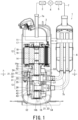
- Fig. 1 is a view illustrating a vertical section of the rotary compressor and an overview of the refrigeration cycle apparatus according to the first embodiment of the present invention.
- a refrigeration cycle apparatus 1 includes a rotary compressor 2, a condenser 3 as a radiator, an expansion device 4, and an evaporator 5 as a heat absorber, an accumulator 6, and a refrigerant pipe 7.
- the refrigerant pipe 7 connects the rotary compressor 2, the condenser 3, the expansion device 4, the evaporator 5 and the accumulator 6 in sequence to circulate a refrigerant.
- the rotary compressor 2 includes a hermetic casing 11, an electric motor 12 provided at an upper part in the hermetic casing 11, a compression mechanism 13 provided at a lower part in the hermetic casing 11, a rotating shaft 14 that transmits a rotational driving force generated by the electric motor 12 to the compression mechanism 13, a main bearing 15 that rotatably supports the rotating shaft 14, and a secondary bearing 16 that rotatably supports the rotating shaft 14 in corporation with the main bearing 15.
- the hermetic casing 11 is cylindrical.
- the hermetic casing 11 includes hemispherical end plates provided above and below, and a tubular body part.
- a suction pipe 7b that leads a refrigerant to the rotary compressor 2 is connected to the body part of the hermetic casing 11.
- a discharge pipe 7a for discharging the refrigerant from the rotary compressor 2 is connected to the top end plate of the hermetic casing 11.
- the electric motor 12 generates a driving force that rotationally drives the compression mechanism 13.
- the electric motor 12 includes a stator 18 fixed to an inner wall of the hermetic casing 11, and a rotor 19 surrounded by the stator 18 and provided on the rotating shaft 14.
- the rotary compressor 2 includes an oil separation portion 17 provided on a top surface of the rotor 19, that is, a surface facing the top end plate of the hermetic casing 11.
- the oil separation portion 17 separates lubricating oil mixed in a gaseous refrigerant compressed by the compression mechanism 13 to be discharged into the hermetic casing 11.
- the rotating shaft 14 couples the electric motor 12 and the compression mechanism 13 to each other.
- the rotating shaft 14 transmits the driving force generated by the electric motor 12 to the compression mechanism 13.
- a middle portion 14a of the rotating shaft 14 is rotatably supported by the main bearing 15.
- a lower end portion 14b of the rotating shaft 14 is rotatably supported by the secondary bearing 16.
- the main bearing 15 and the secondary bearing 16 are also part of the compression mechanism 13, and sandwich the compression mechanism 13 from above and below. In other words, the rotating shaft 14 penetrates through the compression mechanism 13.
- the rotating shaft 14 includes a plurality of eccentric portions 21 between the middle portion 14a supported by the main bearing 15 and the lower end portion 14b supported by the secondary bearing 16.
- the eccentric portion 21 close to the main bearing 15 is referred to as a first eccentric portion 22, and the eccentric portion 21 close to the secondary bearing 16 is referred to as a second eccentric portion 23.
- Each of the eccentric portions 21 is a disk, or a circular column having a center that does not coincide with a center of the rotating shaft 14.
- the center of each of the eccentric portions 21 is eccentric from the rotating shaft 14 with a phase difference of about 180° (degrees).
- the first eccentric portion 22 is disposed on an upper side close to the electric motor 12, and the second eccentric portion 23 is disposed on a lower side far from the electric motor 12.
- the compression mechanism 13 sucks and compresses a gaseous refrigerant and then discharges the refrigerant, by the electric motor 12 rotationally driving the rotating shaft 14.
- the compression mechanism 13 is accommodated in the hermetic casing 11 and is disposed at a lower part of the hermetic casing 11.
- a lubricating oil (not illustrated) is stored in the lower part of the hermetic casing 11, and a lower part of the compression mechanism 13 is immersed in the lubricating oil.
- the compression mechanism 13 includes a plurality of compression mechanisms.
- the compression mechanism 13 includes a first compression mechanism 25, a second compression mechanism 26, and a partition plate 27 provided between the first compression mechanism 25 and the second compression mechanism 26.
- the first compression mechanism 25 includes a first cylinder 32 having a cylindrical-shaped first cylinder chamber 31, and an annular first roller 33 disposed in the first cylinder chamber 31.
- the second compression mechanism 26 includes a second cylinder 42 having a cylindrical-shaped second cylinder chamber 41, and an annular second roller 43 disposed in the second cylinder chamber 41.
- the first cylinder 32 and the second cylinder 42 are disposed so as to be stacked in an axial direction of the rotating shaft 14.
- the first cylinder 32 on the upper side is disposed on a side close to the electric motor 12.
- the first cylinder 32 is fixed to the hermetic casing 11 via a frame 24.
- the frame 24 is fixed to the hermetic casing 11 by welded portions 51 at a plurality of spots.
- the first cylinder 32 is fixed to the frame 24 by a fastening member such as a bolt.
- the welded portion 51 is formed by spot welding, for example.
- the first cylinder chamber 31 and center of the second cylinder chamber 41 substantially overlap a center of the rotating shaft 14.
- These cylinder chambers 31 and 41 have substantially a same diameter dimensions and a same height dimension, that is, a dimension in the axial direction of the rotating shaft 14.
- the first cylinder chamber 31 is a space inside of the first cylinder 32, and is closed by the main bearing 15 and the partition plate 27.
- the first eccentric portion 22 of the rotating shaft 14 is disposed in the first cylinder chamber 31.
- the second cylinder chamber 41 is a space inside of the second cylinder 42, and is closed by the partition plate 27 and the secondary bearing 16.
- the second eccentric portion 23 of the rotating shaft 14 is disposed in the second cylinder chamber 41.
- the main bearing 15 on the upper side is fixed to the first cylinder 32 by a fastening member 52 such as a bolt.
- the compression mechanism 13 includes a first discharge valve mechanism (not illustrated) provided at the main bearing 15 on the upper side, and has a discharge port and a discharge valve for discharging a refrigerant compressed in the first cylinder chamber 31, and a first discharge muffler 53.
- the first discharge muffler 53 has a discharge hole (not illustrated).
- the first discharge muffler 53 covers the first discharge valve mechanism.
- the discharge port of the first discharge valve mechanism is connected to the first cylinder chamber 31. When the inside of the first cylinder chamber 31 reaches a predetermined pressure along with a compression action of the compression mechanism 13, the discharge valve opens the discharge port to discharge the compressed refrigerant into the first discharge muffler 53.
- the secondary bearing 16 on the lower side is fixed to the first cylinder 32 by the fastening member 52 such as a bolt.
- the fastening member 52 penetrates through the second cylinder 42 and the partition plate 27 to reach the first cylinder 32.
- the compression mechanism 13 includes a second discharge valve mechanism (not illustrated) provided at the secondary bearing 16 on the lower side and has a discharge port and a discharge valve for discharging the refrigerant compressed in the second cylinder chamber 41, and a second discharge muffler 54.
- the second discharge muffler 54 covers the second discharge valve mechanism.
- the discharge port of the second discharge mechanism is connected to the second cylinder chamber 41. When an inside of the second cylinder chamber 41 reaches a predetermined pressure along with a compression action of the compression mechanism 13, the discharge valve opens the discharge port to discharge the compressed refrigerant into the second discharge muffler 54.
- the first roller 33 is fitted onto a peripheral surface of the first eccentric portion 22 and accommodated in the first cylinder chamber 31. Along with the rotation of the rotating shaft 14, the first roller 33 eccentrically rotates while a part of its outer peripheral surface is in line contact with the first cylinder 32 along the inner peripheral surface of the first cylinder 32.
- the second roller 43 is fitted onto a peripheral surface of the second eccentric portion 23 and accommodated in the second cylinder chamber 41. Along with the rotation of the rotating shaft 14, the second roller 43 eccentrically rotates while a part of its outer peripheral surface is in line contact with the second cylinder 42 along the inner peripheral surface of the second cylinder 42.
- the contact between the first roller 33 and the first cylinder 32, and the contact between the second roller 43 and the second cylinder 42 are not direct contact, but indirect contact with an oil film (not illustrated) therebetween.
- the contact with the oil film inbetween is simply expressed as "contact”. The same applies to contact between the first roller 33 and the first eccentric portion 22, between the second roller 43 and the second eccentric portion 23, between the first roller 33 and the main bearing 15, between the second roller 43 and the secondary bearing 16, between the first roller 33 and the partition plate 27, and between the second roller 43 and the partition plate 27.
- the first cylinder 32 of the first compression mechanism 25 of the compression mechanism 13 will be described in detail.
- Fig. 2 illustrates a sectional view taken along line A-A in Fig. 1 illustrating the cylinder of the rotary compressor according to the first embodiment. Note that since the first compression mechanism 25 and the second compression mechanism 26 have substantially a same configuration, explanation of the second cylinder 42 of the second compression mechanism 26 will be omitted.
- the first cylinder 32 has a blade groove 64 recessed radially outward.
- the blade groove 64 extends over the entire axial direction of the rotating shaft 14 in the first cylinder 32.
- An outer end portion (also referred to as a rear end portion) in a radial direction of the blade groove 64 leads to an inside of the hermetic casing 11. That is, the blade groove 64 opens to the cylinder chamber 31.
- the blade groove 64 accommodates a blade 61 reciprocally movable along a radial direction of the first cylinder chamber 31.
- the blade 61 receives a force inwardly in the radial direction of the first cylinder chamber 31 by a biasing means, for example, a coil spring.
- An inner end surface (also called a tip end surface) of the blade 61 in the radial direction of the first cylinder chamber 31 is in contact with an outer peripheral surface 65 of the first roller in the first cylinder chamber 31.
- the blade 61 reciprocally moves in the first cylinder chamber 31 while being in contact with the outer peripheral surface 65 of the first roller.
- the first cylinder chamber 31 is divided into a suction chamber and a compression chamber by the first roller 33 and the blade 61.
- a compression operation is performed in the first cylinder chamber 31 by the eccentric rotation of the first roller 33 and the reciprocal movement of the blade 61.
- the first cylinder 32 has a suction hole 62 positioned on a back side of the blade groove 64 along a rotation direction of the first roller 33.
- the suction hole 62 penetrates through the first cylinder 32 in the radial direction.
- An outer end portion in the radial direction, of the suction hole 62 is connected to the suction pipe 7b.
- An inner end portion in the radial direction of the suction hole 62 opens to the first cylinder chamber 31.
- An inner peripheral surface of the first cylinder 32 has a discharge groove 63 positioned on a front side of the blade groove 64 along the rotation direction of the first roller 33.
- the discharge groove 63 leads to the discharge pipe 7a via the discharge port, the first discharge muffler 53, and the space in the hermetic casing 11 that are described above.
- the rotating shaft 14 rotates around a shaft center line 0 together with the rotor 19. Then, along with the rotation of the rotating shaft 14, the first eccentric portion 22 and the first roller 33 eccentrically rotate in the first cylinder chamber 31. At this time, the first roller 33 contacts the inner peripheral surface of the first cylinder 32, whereby the refrigerant is taken into the first cylinder chamber 31 through the suction pipe 7b, and the refrigerant taken in is compressed in the first cylinder chamber 31.
- the blade 61 reciprocally moves in the radial direction of the first cylinder chamber 31 along with the eccentric rotation of the first roller 33.
- the refrigerant is sucked into the suction chamber through the suction pipe 7b and the suction hole 62, and the refrigerant sucked from the suction hole 62 is compressed in the compression chamber.
- the compressed refrigerant is discharged outside of the first cylinder chamber 31 through the discharge groove 63 of the main bearing 15, and thereafter, discharged into the hermetic casing 11 through a coupling hole (not illustrated) outside of the first cylinder chamber 31.
- the refrigerant discharged into the hermetic casing 11 is sent to the condenser 3 through the discharge pipe 7a.
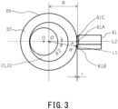
- Fig. 3 is a view illustrating a positional relationship between the roller and the blade in Fig. 2 .
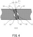
- Fig. 4 is a view illustrating a partially section taken along line B-B in Fig. 2 of the rotary compressor according to the first embodiment.
- Fig. 2 and Fig. 3 illustrate a state where the roller is positioned at the top dead center.
- the blade groove 64 has sliding surfaces that guide reciprocal movement of the blade 61.
- the sliding surfaces are provided to be inclined with respect to the axial direction of the rotating shaft 14.
- a first wall surface 91 and a second wall surface 92 of the first cylinder 32 that are the sliding surfaces of the blade groove 64 are inclined with respect to the axial direction of the rotating shaft 14.
- An upper end side of the sliding surface of the blade groove 64 may be inclined to either one of the rotation direction and a reverse rotation direction of the first roller 33.
- the blade groove 64 is easily manufactured by performing broaching and polishing in a state where the first cylinder 32 is inclined.
- the first wall surface 91 and the second wall surface 92 are inclined with respect to the axial direction of the rotating shaft 14. Therefore, the blade 61 is accommodated in the blade groove 64 in a state of being inclined with respect to the axial direction of the rotating shaft 14.
- the blade 61 is in a rectangular parallelepiped shape extending in the radial direction of the first cylinder 32, and has a first end surface 71 and a second end surface 72 that face each other in a circumferential direction of the first roller 33, and a third end surface 81 and a fourth end surface 82 that face each other in the axial direction of the rotating shaft 14.
- the first end surface 71, the second end surface 72, and the first wall surface 91 and the second wall surface 92 of the first cylinder 32 are substantially parallel.
- the sliding surface of the blade groove 64 is inclined with respect to the axial direction of the rotating shaft 14. Therefore, a gap r occurs to upper and lower end portions of a site where the tip end surface of the blade 61 and the outer peripheral surface 65 of the first roller contact each other.
- the tip end surface of the blade 61 is in contact with the outer peripheral surface 65 of the first roller only by a part of an entire length, and the upper and lower end portions of the tip end surface of the blade 61 are not in contact with the outer peripheral surface 65 of the first roller.
- the tip end surface of the blade 61 comes in point contact with the outer peripheral surface 65 of the first roller. If a center of the tip end surface of the blade 61 is in point contact with the outer peripheral surface 65 of the first roller, the portion closer to the two ends of the tip end surface of the blade 61 will be farther from the outer peripheral surface 65 of the first roller, and both ends of the tip end surface of the blade 61 will be farthest from the outer peripheral surface 65 of the first roller.
- the tip end surface of the blade 61 is in the axial direction of the rotating shaft 14, the longer a contact distance will be between the tip end surface of the blade 61 and the outer peripheral surface 65 of the first roller.
- the tip end surface of the blade 61 is made parallel to the axial direction of the rotating shaft 14, the tip end surface of the blade 61 contacts the outer peripheral surface 65 of the first roller over an entire height.
- An inclination angle ⁇ 1 of the sliding surface of the blade groove 64 is preferably 1° to 3°.
- ⁇ 1 is an angle at which the sliding surface of the blade groove 64 is inclined to the axial direction (shaft center line 0) of the rotating shaft 14.
- the tip end surface of the blade 61 has a center portion 61A of the blade, that is, a contact portion between the first roller 33 and the blade 61, an upper end portion 61B of the blade, and a lower end portion 61C of the blade.
- a gap r is provided between the upper end portion 61B and the outer peripheral surface 65 of the first roller, and between the lower end portion 61C and the outer peripheral surface 65 of the first roller. The gap r becomes maximum when the position of the first roller 33 eccentrically rotating in the first cylinder chamber 31 of the first cylinder 32 is at the top dead center or the bottom dead center.
- the upper end portion 61B of the blade and the lower end portion 61C of the blade each has the maximum gap r by which the upper end portion 61B and the lower end portion 61C are farthest from the outer peripheral surface 65 of the first roller, when a portion near the center portion 61A of the blade contacts the outer peripheral surface 65 of the first roller.
- the maximum gap r can be obtained from a difference between a radius R of the first roller 33, and a distance R' from a center O' of the first roller 33 to the upper end portion 61B of the blade.
- an included angle formed by a line segment L1 connecting the center O' of the first roller 33 and the upper end portion 61B of the blade, and a line segment L2 connecting the center O' of the first roller 33 and the center portion 61A of the blade is defined as ⁇ 2.
- the maximum gap r changes by about 0.001 milli-metres to 0.01 milli-metres when the inclination angle ⁇ 1 is in a range of 1° to 3°. With such an angle range of ⁇ 1, it is possible to reduce an amount of refrigerant leaking from the gap formed by the tip end surface of the blade 61 and the outer peripheral surface 65 of the first roller to a very small amount.
- the tip end surface of the blade 61 and the outer peripheral surface 65 of the first roller are prevented from locally contacting each other while the amount of the refrigerant leaking from the gap r between the tip end surface of the blade 61 and the outer peripheral surface 65 of the first roller is minimized.
- Fig. 5(a), Fig. 5(b), and Fig. 5(c) show a state where a relative inclination occurs, and the tip end surface of the blade 61 and the outer peripheral surface 65 of the first roller contact each other on a lower end side
- Fig. 5(b) shows a state without a relative inclination
- Fig. 5(c) shows a state where a relative inclination occurs, and the tip end surface of the blade 61 and the outer peripheral surface 65 of the first roller contact each other on an upper end side.
- the sliding surface of the blade groove 64 is inclined with respect to the axial direction of the rotating shaft 14. Accordingly, the tip end surface of the blade 61 gently contacts the outer peripheral surface 65 of the first roller from the center portion to the upper end side or the lower end side, and local contact of the tip end surface of the blade 61 and the outer peripheral surface 65 of the first roller can be relieved.
- the maximum gap r at the top dead center or the bottom dead center is described, but by optimizing the outer diameter dimension of the first roller 33, an eccentric amount of the eccentric portion, the height of the blade 61, a circular arc shape of the tip end surface of the blade 61, and the inclination of the blade 61, local contact is also relieved even when the first roller 33 is in positions other than the top dead center and the bottom dead center.
- a second embodiment of the rotary compressor and the refrigeration cycle apparatus according to the present invention will be described with reference to Fig. 6 .
- same components as the respective components of the first embodiment in Fig. 1 to Fig. 5 are denoted by the same reference signs, and explanation thereof will be omitted.
- What the second embodiment differs from the first embodiment is a shape of the blade 61.
- Fig. 6 illustrates a sectional view taken along line B-B in Fig. 2 of a rotary compressor according to the second embodiment.
- upper and lower end surfaces of the blade 61, a third end surface 81 and a fourth end surface 82 that face each other in an axial direction of a rotating shaft 14 may be aligned in a same straight line with an upper and lower flat end surfaces of a first cylinder 32.
- the upper and lower end surfaces of the blade 61 and the upper and lower flat end surfaces of the first cylinder 32 are substantially parallel with a lower end surface of a main bearing 15 and an upper end surface of a partition plate 27.
- a sectional shape in the radial direction of the first cylinder chamber 31 may be a parallelogram.
- a rotary compressor 2 in which the upper and lower end surfaces of the blade 61 are aligned in the same straight line with the upper and lower flat end surfaces of the first cylinder 32 prevents degradation of compression performance due to refrigerant leakage from the gaps between the blade 61 and the main bearing 15 and between the blade 61 and the partition plate 27.
- the rotary compressor 2 prevents the blade 61 from unilaterally contacting the blade groove 64.
Landscapes
- Engineering & Computer Science (AREA)
- Mechanical Engineering (AREA)
- General Engineering & Computer Science (AREA)
- Rotary Pumps (AREA)
- Applications Or Details Of Rotary Compressors (AREA)
Abstract
To provide a rotary compressor easy to manufacture and highly reliable, and a refrigeration cycle apparatus equipped with this compressor. The rotary compressor (2) includes: a hermetic casing (11); an electric motor (12) accommodated in the hermetic casing and including a stator (18) and a rotor (19); and a compression mechanism (13) coupled to the rotor by a rotating shaft (14). The compression mechanism includes a cylinder (32) including a cylindrical-shaped cylinder chamber (31), and a blade groove (64) opening to the cylinder chamber, a roller (33) eccentrically rotatable in the cylinder chamber, and a blade (61) provided in the blade groove, contacting an outer peripheral surface of the roller, and disposed to be reciprocally movable along with eccentric rotation of the roller in a radial direction of the cylinder chamber and dividing the cylinder chamber into a suction chamber and a compression chamber. The blade groove has sliding surfaces inclined with respect to an axial direction of the rotating shaft, and guiding reciprocal movement of the blade.
Description
- An embodiment of the present invention relates to a rotary compressor and a refrigeration cycle apparatus.
- A refrigeration cycle apparatus including a rotary compressor, such as an air conditioner, is known. The rotary compressor includes an electric motor accommodated in a hermetic casing, a compression mechanism, a cylinder having a cylindrical-shaped cylinder chamber and a blade groove, a roller eccentrically rotatable in the cylinder chamber, and a blade that is disposed in the blade groove, contacts an outer peripheral surface of the roller along with eccentric rotation of the roller, and divides the cylinder chamber into a suction chamber and a compression chamber.
- In order to prevent local abnormal wear due to unilateral touch between the tip end surface of the blade and the outer peripheral surface of the roller, there are known techniques for providing crowning on at least either one of the tip end surface of the blade or the outer peripheral surface of the roller as described in Patent Document 1 (
JP H06-147152 A JP 2005-30232 A - However, the techniques disclosed by Patent Document 1 and
Patent Document 2 require the tip end surface of the blade or the blade groove to be specially processed into a curved shape, which may lead to reduction in production capacity. - It is an object of the present invention to provide a rotary compressor easy to manufacture and highly reliable, and a refrigeration cycle apparatus equipped with this compressor.
- To achieve the above object, an aspect of the present invention provides the rotary compressor includes a hermetic casing (11), an electric motor (12) accommodated in the hermetic casing and including a stator (18) and a rotor (19), and a compression mechanism (13) coupled to the rotor by a rotating shaft (14). The compression mechanism includes a cylinder (32) including a cylindrical-shaped cylinder chamber (31), and a blade groove (64) opening to the cylinder chamber, a roller (33) eccentrically rotatable in the cylinder chamber, and a blade (61) provided in the blade groove, contacting an outer peripheral surface of the roller, and disposed to be reciprocally movable along with eccentric rotation of the roller in a radial direction of the cylinder chamber, and dividing the cylinder chamber into a suction chamber and a compression chamber. The blade groove has sliding surfaces inclined with respect to an axial direction of the rotating shaft, and guiding reciprocal movement of the blade.
- To achieve the above object, an aspect of the present invention provides the refrigeration cycle apparatus includes the rotary compressor, a condenser, an expansion device, an evaporator (5), and a refrigerant pipe connecting the rotary compressor, the condenser, the expansion device, and the evaporator to circulate a refrigerant.
-
-
Fig. 1 is a view illustrating a vertical section of a rotary compressor and an overview of a refrigeration cycle apparatus according to a first embodiment; -
Fig. 2 is a sectional view taken along line A-A inFig. 1 , illustrating a cylinder of the rotary compressor according to the first embodiment; -
Fig. 3 is a view illustrating a positional relationship between a roller and a blade inFig. 2 ; -
Fig. 4 is a sectional view taken along line B-B inFig. 2 of the rotary compressor according to the first embodiment; -
Fig. 5A, 5B, and 5C are contact states diagrams between a tip end surface of the blade and an outer peripheral surface of the roller of the rotary compressor according to the first embodiment; and -
Fig. 6 is a sectional view taken along line B-B inFig. 2 of a rotary compressor according to a second embodiment. - Hereinafter, a first embodiment of a rotary compressor and a refrigeration cycle apparatus according to the present invention will be described with reference to
Fig. 1 to Fig. 5 . -
Fig. 1 is a view illustrating a vertical section of the rotary compressor and an overview of the refrigeration cycle apparatus according to the first embodiment of the present invention. - As illustrated in
Fig. 1 , a refrigeration cycle apparatus 1 according to the first embodiment of the present invention includes arotary compressor 2, acondenser 3 as a radiator, anexpansion device 4, and anevaporator 5 as a heat absorber, anaccumulator 6, and a refrigerant pipe 7. The refrigerant pipe 7 connects therotary compressor 2, thecondenser 3, theexpansion device 4, theevaporator 5 and theaccumulator 6 in sequence to circulate a refrigerant. - The
rotary compressor 2 according to the first embodiment of the present invention includes ahermetic casing 11, anelectric motor 12 provided at an upper part in thehermetic casing 11, acompression mechanism 13 provided at a lower part in thehermetic casing 11, a rotatingshaft 14 that transmits a rotational driving force generated by theelectric motor 12 to thecompression mechanism 13, amain bearing 15 that rotatably supports the rotatingshaft 14, and asecondary bearing 16 that rotatably supports the rotatingshaft 14 in corporation with the main bearing 15. - The
hermetic casing 11 is cylindrical. Thehermetic casing 11 includes hemispherical end plates provided above and below, and a tubular body part. Asuction pipe 7b that leads a refrigerant to therotary compressor 2 is connected to the body part of thehermetic casing 11. Adischarge pipe 7a for discharging the refrigerant from therotary compressor 2 is connected to the top end plate of thehermetic casing 11. - The
electric motor 12 generates a driving force that rotationally drives thecompression mechanism 13. Theelectric motor 12 includes astator 18 fixed to an inner wall of thehermetic casing 11, and arotor 19 surrounded by thestator 18 and provided on the rotatingshaft 14. - The
rotary compressor 2 includes an oil separation portion 17 provided on a top surface of therotor 19, that is, a surface facing the top end plate of thehermetic casing 11. The oil separation portion 17 separates lubricating oil mixed in a gaseous refrigerant compressed by thecompression mechanism 13 to be discharged into thehermetic casing 11. - The rotating
shaft 14 couples theelectric motor 12 and thecompression mechanism 13 to each other. The rotatingshaft 14 transmits the driving force generated by theelectric motor 12 to thecompression mechanism 13. Amiddle portion 14a of the rotatingshaft 14 is rotatably supported by the main bearing 15. Alower end portion 14b of the rotatingshaft 14 is rotatably supported by thesecondary bearing 16. The main bearing 15 and thesecondary bearing 16 are also part of thecompression mechanism 13, and sandwich thecompression mechanism 13 from above and below. In other words, therotating shaft 14 penetrates through thecompression mechanism 13. - The rotating
shaft 14 includes a plurality of eccentric portions 21 between themiddle portion 14a supported by the main bearing 15 and thelower end portion 14b supported by thesecondary bearing 16. Of the plurality of eccentric portions 21, the eccentric portion 21 close to the main bearing 15 is referred to as a first eccentric portion 22, and the eccentric portion 21 close to thesecondary bearing 16 is referred to as a second eccentric portion 23. Each of the eccentric portions 21 is a disk, or a circular column having a center that does not coincide with a center of the rotatingshaft 14. The center of each of the eccentric portions 21 is eccentric from the rotatingshaft 14 with a phase difference of about 180° (degrees). The first eccentric portion 22 is disposed on an upper side close to theelectric motor 12, and the second eccentric portion 23 is disposed on a lower side far from theelectric motor 12. - The
compression mechanism 13 sucks and compresses a gaseous refrigerant and then discharges the refrigerant, by theelectric motor 12 rotationally driving the rotatingshaft 14. Thecompression mechanism 13 is accommodated in thehermetic casing 11 and is disposed at a lower part of thehermetic casing 11. A lubricating oil (not illustrated) is stored in the lower part of thehermetic casing 11, and a lower part of thecompression mechanism 13 is immersed in the lubricating oil. - The
compression mechanism 13 includes a plurality of compression mechanisms. In other words, thecompression mechanism 13 includes afirst compression mechanism 25, asecond compression mechanism 26, and apartition plate 27 provided between thefirst compression mechanism 25 and thesecond compression mechanism 26. - The
first compression mechanism 25 includes afirst cylinder 32 having a cylindrical-shapedfirst cylinder chamber 31, and an annularfirst roller 33 disposed in thefirst cylinder chamber 31. Thesecond compression mechanism 26 includes asecond cylinder 42 having a cylindrical-shapedsecond cylinder chamber 41, and an annularsecond roller 43 disposed in thesecond cylinder chamber 41. - The
first cylinder 32 and thesecond cylinder 42 are disposed so as to be stacked in an axial direction of the rotatingshaft 14. Thefirst cylinder 32 on the upper side is disposed on a side close to theelectric motor 12. Thefirst cylinder 32 is fixed to thehermetic casing 11 via aframe 24. - The
frame 24 is fixed to thehermetic casing 11 bywelded portions 51 at a plurality of spots. Thefirst cylinder 32 is fixed to theframe 24 by a fastening member such as a bolt. Thewelded portion 51 is formed by spot welding, for example. - Center of the
first cylinder chamber 31 and center of thesecond cylinder chamber 41 substantially overlap a center of the rotatingshaft 14. Thesecylinder chambers shaft 14. Thefirst cylinder chamber 31 is a space inside of thefirst cylinder 32, and is closed by the main bearing 15 and thepartition plate 27. The first eccentric portion 22 of the rotatingshaft 14 is disposed in thefirst cylinder chamber 31. Thesecond cylinder chamber 41 is a space inside of thesecond cylinder 42, and is closed by thepartition plate 27 and thesecondary bearing 16. The second eccentric portion 23 of the rotatingshaft 14 is disposed in thesecond cylinder chamber 41. - The
main bearing 15 on the upper side is fixed to thefirst cylinder 32 by afastening member 52 such as a bolt. Thecompression mechanism 13 includes a first discharge valve mechanism (not illustrated) provided at themain bearing 15 on the upper side, and has a discharge port and a discharge valve for discharging a refrigerant compressed in thefirst cylinder chamber 31, and afirst discharge muffler 53. Thefirst discharge muffler 53 has a discharge hole (not illustrated). Thefirst discharge muffler 53 covers the first discharge valve mechanism. The discharge port of the first discharge valve mechanism is connected to thefirst cylinder chamber 31. When the inside of thefirst cylinder chamber 31 reaches a predetermined pressure along with a compression action of thecompression mechanism 13, the discharge valve opens the discharge port to discharge the compressed refrigerant into thefirst discharge muffler 53. - The
secondary bearing 16 on the lower side is fixed to thefirst cylinder 32 by thefastening member 52 such as a bolt. Thefastening member 52 penetrates through thesecond cylinder 42 and thepartition plate 27 to reach thefirst cylinder 32. Thecompression mechanism 13 includes a second discharge valve mechanism (not illustrated) provided at thesecondary bearing 16 on the lower side and has a discharge port and a discharge valve for discharging the refrigerant compressed in thesecond cylinder chamber 41, and asecond discharge muffler 54. Thesecond discharge muffler 54 covers the second discharge valve mechanism. The discharge port of the second discharge mechanism is connected to thesecond cylinder chamber 41. When an inside of thesecond cylinder chamber 41 reaches a predetermined pressure along with a compression action of thecompression mechanism 13, the discharge valve opens the discharge port to discharge the compressed refrigerant into thesecond discharge muffler 54. - The
first roller 33 is fitted onto a peripheral surface of the first eccentric portion 22 and accommodated in thefirst cylinder chamber 31. Along with the rotation of therotating shaft 14, thefirst roller 33 eccentrically rotates while a part of its outer peripheral surface is in line contact with thefirst cylinder 32 along the inner peripheral surface of thefirst cylinder 32. Thesecond roller 43 is fitted onto a peripheral surface of the second eccentric portion 23 and accommodated in thesecond cylinder chamber 41. Along with the rotation of therotating shaft 14, thesecond roller 43 eccentrically rotates while a part of its outer peripheral surface is in line contact with thesecond cylinder 42 along the inner peripheral surface of thesecond cylinder 42. - Note that the contact between the
first roller 33 and thefirst cylinder 32, and the contact between thesecond roller 43 and thesecond cylinder 42 are not direct contact, but indirect contact with an oil film (not illustrated) therebetween. However, for convenience of explanation, the contact with the oil film inbetween is simply expressed as "contact". The same applies to contact between thefirst roller 33 and the first eccentric portion 22, between thesecond roller 43 and the second eccentric portion 23, between thefirst roller 33 and themain bearing 15, between thesecond roller 43 and thesecondary bearing 16, between thefirst roller 33 and thepartition plate 27, and between thesecond roller 43 and thepartition plate 27. - The
first cylinder 32 of thefirst compression mechanism 25 of thecompression mechanism 13 will be described in detail. -
Fig. 2 illustrates a sectional view taken along line A-A inFig. 1 illustrating the cylinder of the rotary compressor according to the first embodiment. Note that since thefirst compression mechanism 25 and thesecond compression mechanism 26 have substantially a same configuration, explanation of thesecond cylinder 42 of thesecond compression mechanism 26 will be omitted. - As illustrated in
Fig. 2 , thefirst cylinder 32 has ablade groove 64 recessed radially outward. Theblade groove 64 extends over the entire axial direction of therotating shaft 14 in thefirst cylinder 32. An outer end portion (also referred to as a rear end portion) in a radial direction of theblade groove 64 leads to an inside of thehermetic casing 11. That is, theblade groove 64 opens to thecylinder chamber 31. - The
blade groove 64 accommodates ablade 61 reciprocally movable along a radial direction of thefirst cylinder chamber 31. Theblade 61 receives a force inwardly in the radial direction of thefirst cylinder chamber 31 by a biasing means, for example, a coil spring. An inner end surface (also called a tip end surface) of theblade 61 in the radial direction of thefirst cylinder chamber 31 is in contact with an outerperipheral surface 65 of the first roller in thefirst cylinder chamber 31. Along with eccentric rotation of thefirst roller 33, theblade 61 reciprocally moves in thefirst cylinder chamber 31 while being in contact with the outerperipheral surface 65 of the first roller. - The
first cylinder chamber 31 is divided into a suction chamber and a compression chamber by thefirst roller 33 and theblade 61. In thecompression mechanism 13, a compression operation is performed in thefirst cylinder chamber 31 by the eccentric rotation of thefirst roller 33 and the reciprocal movement of theblade 61. - The
first cylinder 32 has asuction hole 62 positioned on a back side of theblade groove 64 along a rotation direction of thefirst roller 33. Thesuction hole 62 penetrates through thefirst cylinder 32 in the radial direction. An outer end portion in the radial direction, of thesuction hole 62 is connected to thesuction pipe 7b. An inner end portion in the radial direction of thesuction hole 62 opens to thefirst cylinder chamber 31. An inner peripheral surface of thefirst cylinder 32 has adischarge groove 63 positioned on a front side of theblade groove 64 along the rotation direction of thefirst roller 33. Thedischarge groove 63 leads to thedischarge pipe 7a via the discharge port, thefirst discharge muffler 53, and the space in thehermetic casing 11 that are described above. - An operation of the
compression mechanism 13 will be described. - When electric power is supplied to the
stator 18 of theelectric motor 12, the rotatingshaft 14 rotates around a shaft center line 0 together with therotor 19. Then, along with the rotation of therotating shaft 14, the first eccentric portion 22 and thefirst roller 33 eccentrically rotate in thefirst cylinder chamber 31. At this time, thefirst roller 33 contacts the inner peripheral surface of thefirst cylinder 32, whereby the refrigerant is taken into thefirst cylinder chamber 31 through thesuction pipe 7b, and the refrigerant taken in is compressed in thefirst cylinder chamber 31. - The
blade 61 reciprocally moves in the radial direction of thefirst cylinder chamber 31 along with the eccentric rotation of thefirst roller 33. - Specifically, in the
first cylinder chamber 31, the refrigerant is sucked into the suction chamber through thesuction pipe 7b and thesuction hole 62, and the refrigerant sucked from thesuction hole 62 is compressed in the compression chamber. The compressed refrigerant is discharged outside of thefirst cylinder chamber 31 through thedischarge groove 63 of themain bearing 15, and thereafter, discharged into thehermetic casing 11 through a coupling hole (not illustrated) outside of thefirst cylinder chamber 31. Note that the refrigerant discharged into thehermetic casing 11 is sent to thecondenser 3 through thedischarge pipe 7a. -
Fig. 3 is a view illustrating a positional relationship between the roller and the blade inFig. 2 .Fig. 4 is a view illustrating a partially section taken along line B-B inFig. 2 of the rotary compressor according to the first embodiment. - The case in which the
first roller 33 in thefirst cylinder chamber 31 is positioned at a top dead center or a bottom dead center will be described.Fig. 2 andFig. 3 illustrate a state where the roller is positioned at the top dead center. - As illustrated in
Fig. 2 to Fig. 4 , theblade groove 64 has sliding surfaces that guide reciprocal movement of theblade 61. The sliding surfaces are provided to be inclined with respect to the axial direction of therotating shaft 14. In other words, afirst wall surface 91 and asecond wall surface 92 of thefirst cylinder 32 that are the sliding surfaces of theblade groove 64 are inclined with respect to the axial direction of therotating shaft 14. - An upper end side of the sliding surface of the
blade groove 64 may be inclined to either one of the rotation direction and a reverse rotation direction of thefirst roller 33. - The
blade groove 64 is easily manufactured by performing broaching and polishing in a state where thefirst cylinder 32 is inclined. - The
first wall surface 91 and thesecond wall surface 92 are inclined with respect to the axial direction of therotating shaft 14. Therefore, theblade 61 is accommodated in theblade groove 64 in a state of being inclined with respect to the axial direction of therotating shaft 14. - As illustrated in
Fig. 2 to Fig. 4 , theblade 61 is in a rectangular parallelepiped shape extending in the radial direction of thefirst cylinder 32, and has a first end surface 71 and asecond end surface 72 that face each other in a circumferential direction of thefirst roller 33, and athird end surface 81 and afourth end surface 82 that face each other in the axial direction of therotating shaft 14. The first end surface 71, thesecond end surface 72, and thefirst wall surface 91 and thesecond wall surface 92 of thefirst cylinder 32 are substantially parallel. - With
Fig. 3 andFig. 4 , a basic dimensional relationship of the roller and the blade will be described. - The sliding surface of the
blade groove 64 is inclined with respect to the axial direction of therotating shaft 14. Therefore, a gap r occurs to upper and lower end portions of a site where the tip end surface of theblade 61 and the outerperipheral surface 65 of the first roller contact each other. In other words, the tip end surface of theblade 61 is in contact with the outerperipheral surface 65 of the first roller only by a part of an entire length, and the upper and lower end portions of the tip end surface of theblade 61 are not in contact with the outerperipheral surface 65 of the first roller. - Here, if the tip end surface of the
blade 61 is orthogonal to the axial direction of therotating shaft 14, the tip end surface of theblade 61 comes in point contact with the outerperipheral surface 65 of the first roller. If a center of the tip end surface of theblade 61 is in point contact with the outerperipheral surface 65 of the first roller, the portion closer to the two ends of the tip end surface of theblade 61 will be farther from the outerperipheral surface 65 of the first roller, and both ends of the tip end surface of theblade 61 will be farthest from the outerperipheral surface 65 of the first roller. The more erected the tip end surface of theblade 61 is in the axial direction of therotating shaft 14, the longer a contact distance will be between the tip end surface of theblade 61 and the outerperipheral surface 65 of the first roller. When the tip end surface of theblade 61 is made parallel to the axial direction of therotating shaft 14, the tip end surface of theblade 61 contacts the outerperipheral surface 65 of the first roller over an entire height. - Since the respective upper and lower end portions of the tip end surface of the
blade 61 do not locally contact the outerperipheral surface 65 of the first roller, no extreme pressure occurs to the tip end surface of theblade 61. Accordingly, the oil film on the sliding portion between the tip end surface of theblade 61 and the outerperipheral surface 65 of the first roller does not break, and there is no risk of occurrence of seizure or abnormal wear. - An inclination angle θ1 of the sliding surface of the
blade groove 64 is preferably 1° to 3°. Here, θ1 is an angle at which the sliding surface of theblade groove 64 is inclined to the axial direction (shaft center line 0) of therotating shaft 14. - The tip end surface of the
blade 61 has acenter portion 61A of the blade, that is, a contact portion between thefirst roller 33 and theblade 61, anupper end portion 61B of the blade, and alower end portion 61C of the blade. A gap r is provided between theupper end portion 61B and the outerperipheral surface 65 of the first roller, and between thelower end portion 61C and the outerperipheral surface 65 of the first roller. The gap r becomes maximum when the position of thefirst roller 33 eccentrically rotating in thefirst cylinder chamber 31 of thefirst cylinder 32 is at the top dead center or the bottom dead center. In other words, theupper end portion 61B of the blade and thelower end portion 61C of the blade each has the maximum gap r by which theupper end portion 61B and thelower end portion 61C are farthest from the outerperipheral surface 65 of the first roller, when a portion near thecenter portion 61A of the blade contacts the outerperipheral surface 65 of the first roller. - Based on
Fig. 3 , the maximum gap r can be obtained from a difference between a radius R of thefirst roller 33, and a distance R' from a center O' of thefirst roller 33 to theupper end portion 61B of the blade.
- Here, in
Fig. 3 , an included angle formed by a line segment L1 connecting the center O' of thefirst roller 33 and theupper end portion 61B of the blade, and a line segment L2 connecting the center O' of thefirst roller 33 and thecenter portion 61A of the blade is defined as θ2. - In a general rotary compressor, the maximum gap r changes by about 0.001 milli-metres to 0.01 milli-metres when the inclination angle θ1 is in a range of 1° to 3°. With such an angle range of θ1, it is possible to reduce an amount of refrigerant leaking from the gap formed by the tip end surface of the
blade 61 and the outerperipheral surface 65 of the first roller to a very small amount. - By setting the inclination angle θ1 of the sliding surface of the
blade groove 64 to 1° to 3°, the tip end surface of theblade 61 and the outerperipheral surface 65 of the first roller are prevented from locally contacting each other while the amount of the refrigerant leaking from the gap r between the tip end surface of theblade 61 and the outerperipheral surface 65 of the first roller is minimized. - During actual operation, the tip end surface of the
blade 61 and the outerperipheral surface 65 of the first roller are in contact with each other with an inclination accompanied by relative fluctuations, as illustrated inFig. 5(a), Fig. 5(b), and Fig. 5(c) . As conceivable patterns of the inclination, for example,Fig. 5(a) shows a state where a relative inclination occurs, and the tip end surface of theblade 61 and the outerperipheral surface 65 of the first roller contact each other on a lower end side,Fig. 5(b) shows a state without a relative inclination, andFig. 5(c) shows a state where a relative inclination occurs, and the tip end surface of theblade 61 and the outerperipheral surface 65 of the first roller contact each other on an upper end side. - In the embodiment of the present invention, even in a pattern in which the contact between the tip end surface of the
blade 61 and the outerperipheral surface 65 of the first roller are relatively inclined, the sliding surface of theblade groove 64 is inclined with respect to the axial direction of therotating shaft 14. Accordingly, the tip end surface of theblade 61 gently contacts the outerperipheral surface 65 of the first roller from the center portion to the upper end side or the lower end side, and local contact of the tip end surface of theblade 61 and the outerperipheral surface 65 of the first roller can be relieved. - Thereby, even with an easy manufacturing method, abnormal wear due to unilateral touch can be prevented, and the rotary compressor with high reliability can be provided.
- Note that in the embodiment of the present invention, the maximum gap r at the top dead center or the bottom dead center is described, but by optimizing the outer diameter dimension of the
first roller 33, an eccentric amount of the eccentric portion, the height of theblade 61, a circular arc shape of the tip end surface of theblade 61, and the inclination of theblade 61, local contact is also relieved even when thefirst roller 33 is in positions other than the top dead center and the bottom dead center. - Next, a second embodiment of the rotary compressor and the refrigeration cycle apparatus according to the present invention will be described with reference to
Fig. 6 . As for respective components of the second embodiment, same components as the respective components of the first embodiment inFig. 1 to Fig. 5 are denoted by the same reference signs, and explanation thereof will be omitted. What the second embodiment differs from the first embodiment is a shape of theblade 61. -
Fig. 6 illustrates a sectional view taken along line B-B inFig. 2 of a rotary compressor according to the second embodiment. - As illustrated in
Fig. 6 , upper and lower end surfaces of theblade 61, athird end surface 81 and afourth end surface 82 that face each other in an axial direction of arotating shaft 14 may be aligned in a same straight line with an upper and lower flat end surfaces of afirst cylinder 32. Specifically, the upper and lower end surfaces of theblade 61 and the upper and lower flat end surfaces of thefirst cylinder 32 are substantially parallel with a lower end surface of amain bearing 15 and an upper end surface of apartition plate 27. In other words, in theblade 61, a sectional shape in the radial direction of thefirst cylinder chamber 31 may be a parallelogram. - A
rotary compressor 2 in which the upper and lower end surfaces of theblade 61 are aligned in the same straight line with the upper and lower flat end surfaces of thefirst cylinder 32 prevents degradation of compression performance due to refrigerant leakage from the gaps between theblade 61 and themain bearing 15 and between theblade 61 and thepartition plate 27. - Further, the
rotary compressor 2 according to the second embodiment prevents theblade 61 from unilaterally contacting theblade groove 64. - Furthermore, compared with a work of forming crowning on the tip end surface of the
blade 61, making the upper and lower end surfaces of theblade 61 aligned in the same straight line with the upper and lower flat end surfaces of thefirst cylinder 32 is easier, which does not require additional processing, and has no risk of reducing production capacity. -
- 1
- refrigeration cycle apparatus
- 2
- rotary compressor
- 3
- condenser
- 4
- expansion device
- 5
- evaporator
- 6
- accumulator
- 7
- refrigerant pipe
- 7a
- discharge pipe
- 7b
- suction pipe
- 11
- hermetic casing
- 12
- electric motor
- 13
- compression mechanism
- 14
- rotating shaft
- 14a
- middle portion
- 14b
- lower end portion
- 15
- main bearing
- 16
- secondary bearing
- 17
- oil separation portion
- 18
- stator
- 19
- rotor
- 21
- eccentric portion
- 22
- first eccentric portion
- 23
- second eccentric portion
- 24
- frame
- 25
- first compression mechanism
- 26
- second compression mechanism
- 27
- partition plate
- 31
- first cylinder chamber
- 32
- first cylinder
- 33
- first roller
- 41
- second cylinder chamber
- 42
- second cylinder
- 43
- second roller
- 51
- welded portion
- 52
- fastening member
- 53
- first discharge muffler
- 54
- second discharge muffler
- 61
- blade
- 61A
- center portion of the blade
- 61B
- upper end portion of the blade
- 61C
- lower end portion of the blade
- 62
- suction hole
- 63
- discharge groove
- 64
- blade groove
- 65
- outer peripheral surface of the first roller
- 71
- first end surface
- 72
- second end surface
- 81
- third end surface
- 82
- fourth end surface
- 91
- first wall surface
- 92
- second wall surface
Claims (5)
- A rotary compressor (2) comprising:a hermetic casing (11);an electric motor (12) accommodated in the hermetic casing and including a stator (18) and a rotor (19); anda compression mechanism (13) coupled to the rotor by a rotating shaft (14),wherein the compression mechanism includesa cylinder (32) including a cylindrical-shaped cylinder chamber (31), and a blade groove (64) opening to the cylinder chamber,a roller (33) eccentrically rotatable in the cylinder chamber, anda blade (61) provided in the blade groove, contacting an outer peripheral surface of the roller, and disposed to be reciprocally movable along with eccentric rotation of the roller in a radial direction of the cylinder chamber and dividing the cylinder chamber into a suction chamber and a compression chamber, andthe blade groove has sliding surfaces inclined with respect to an axial direction of the rotating shaft, and guiding reciprocal movement of the blade.
- The rotary compressor according to claim 1, wherein the sliding surfaces are provided to be inclined at 1° to 3° with respect to the axial direction of the rotating shaft.
- The rotary compressor according to claim 1 or 2, wherein when the roller is at a top dead center or a bottom dead center, a maximum gap (r) between the blade and the roller and the cylinder chamber is 0.001 milli-metres or more and 0.01 milli-metres or less.
- The rotary compressor according to any one of claims 1 to 3, wherein in the axial direction of the rotating shaft, an end surface of the blade is aligned on a same surface with an end surface of the cylinder chamber.
- A refrigeration cycle apparatus (1), comprising:the rotary compressor (2) according to any one of claims 1 to 4;a condenser (3);an expansion device (4);an evaporator (5); anda refrigerant pipe (7) connecting the rotary compressor, the condenser, the expansion device, and the evaporator to circulate a refrigerant.
Applications Claiming Priority (1)
| Application Number | Priority Date | Filing Date | Title |
|---|---|---|---|
| JP2022150952A JP2024045884A (en) | 2022-09-22 | 2022-09-22 | Rotary compressor and refrigeration cycle device |
Publications (1)
| Publication Number | Publication Date |
|---|---|
| EP4343112A1 true EP4343112A1 (en) | 2024-03-27 |
Family
ID=88068354
Family Applications (1)
| Application Number | Title | Priority Date | Filing Date |
|---|---|---|---|
| EP23197341.3A Withdrawn EP4343112A1 (en) | 2022-09-22 | 2023-09-14 | Rotary compressor and refrigeration cycle apparatus |
Country Status (2)
| Country | Link |
|---|---|
| EP (1) | EP4343112A1 (en) |
| JP (1) | JP2024045884A (en) |
Citations (3)
| Publication number | Priority date | Publication date | Assignee | Title |
|---|---|---|---|---|
| JPH06147152A (en) | 1992-11-06 | 1994-05-27 | Mitsubishi Heavy Ind Ltd | Rotary compressor |
| JP2005030232A (en) | 2003-07-08 | 2005-02-03 | Hitachi Home & Life Solutions Inc | Rotary compressor, and method for processing cylinder therein |
| US20060099102A1 (en) * | 2004-11-05 | 2006-05-11 | Denso Corporation | Vane pump having vanes slanted relative to rotational axis |
-
2022
- 2022-09-22 JP JP2022150952A patent/JP2024045884A/en active Pending
-
2023
- 2023-09-14 EP EP23197341.3A patent/EP4343112A1/en not_active Withdrawn
Patent Citations (3)
| Publication number | Priority date | Publication date | Assignee | Title |
|---|---|---|---|---|
| JPH06147152A (en) | 1992-11-06 | 1994-05-27 | Mitsubishi Heavy Ind Ltd | Rotary compressor |
| JP2005030232A (en) | 2003-07-08 | 2005-02-03 | Hitachi Home & Life Solutions Inc | Rotary compressor, and method for processing cylinder therein |
| US20060099102A1 (en) * | 2004-11-05 | 2006-05-11 | Denso Corporation | Vane pump having vanes slanted relative to rotational axis |
Also Published As
| Publication number | Publication date |
|---|---|
| JP2024045884A (en) | 2024-04-03 |
Similar Documents
| Publication | Publication Date | Title |
|---|---|---|
| JP5441982B2 (en) | Rotary compressor | |
| JP5810221B2 (en) | Rotary compressor and refrigeration cycle equipment | |
| EP4187096B1 (en) | Scroll compressor | |
| JPWO2018078787A1 (en) | Scroll compressor, refrigeration cycle apparatus and shell | |
| WO2018163233A1 (en) | Scroll compressor and refrigeration cycle device | |
| KR20070010082A (en) | Rotary Fluid Machine | |
| EP1674731B1 (en) | Rotary fluid machine | |
| EP2628955A1 (en) | Scroll fluid machine | |
| EP4321756B1 (en) | Scroll compressor | |
| JPWO2013105131A1 (en) | Vane type compressor | |
| JP2013185523A (en) | Compressor and refrigerating cycle device | |
| EP3770378B1 (en) | Rotary compressor | |
| US8734142B2 (en) | Rotation preventing member of a scroll compressor | |
| JP5932608B2 (en) | Vane type compressor | |
| CN214196660U (en) | Vane compressor | |
| CN104884807A (en) | Rotary compressor and refrigeration cycle device | |
| US20190203710A1 (en) | Motor operated compressor | |
| EP3851676B1 (en) | Rotary compressor | |
| JP2024045884A (en) | Rotary compressor and refrigeration cycle device | |
| JP2009108762A (en) | Rotary fluid machine | |
| KR20090012867A (en) | Rotary two stage compressor | |
| JP2005201148A (en) | Scroll fluid machinery | |
| US20250354553A1 (en) | Scroll compressor | |
| JP5821762B2 (en) | Vane type compressor | |
| JP3874018B2 (en) | Scroll type fluid machinery |
Legal Events
| Date | Code | Title | Description |
|---|---|---|---|
| PUAI | Public reference made under article 153(3) epc to a published international application that has entered the european phase |
Free format text: ORIGINAL CODE: 0009012 |
|
| STAA | Information on the status of an ep patent application or granted ep patent |
Free format text: STATUS: REQUEST FOR EXAMINATION WAS MADE |
|
| 17P | Request for examination filed |
Effective date: 20230914 |
|
| AK | Designated contracting states |
Kind code of ref document: A1 Designated state(s): AL AT BE BG CH CY CZ DE DK EE ES FI FR GB GR HR HU IE IS IT LI LT LU LV MC ME MK MT NL NO PL PT RO RS SE SI SK SM TR |
|
| STAA | Information on the status of an ep patent application or granted ep patent |
Free format text: STATUS: THE APPLICATION IS DEEMED TO BE WITHDRAWN |
|
| 18D | Application deemed to be withdrawn |
Effective date: 20240928 |