EP4342704A1 - Work vehicle - Google Patents
Work vehicle Download PDFInfo
- Publication number
- EP4342704A1 EP4342704A1 EP23199486.4A EP23199486A EP4342704A1 EP 4342704 A1 EP4342704 A1 EP 4342704A1 EP 23199486 A EP23199486 A EP 23199486A EP 4342704 A1 EP4342704 A1 EP 4342704A1
- Authority
- EP
- European Patent Office
- Prior art keywords
- battery
- transmission
- motor
- travel
- case
- Prior art date
- Legal status (The legal status is an assumption and is not a legal conclusion. Google has not performed a legal analysis and makes no representation as to the accuracy of the status listed.)
- Pending
Links
Images


Classifications
-
- B—PERFORMING OPERATIONS; TRANSPORTING
- B60—VEHICLES IN GENERAL
- B60K—ARRANGEMENT OR MOUNTING OF PROPULSION UNITS OR OF TRANSMISSIONS IN VEHICLES; ARRANGEMENT OR MOUNTING OF PLURAL DIVERSE PRIME-MOVERS IN VEHICLES; AUXILIARY DRIVES FOR VEHICLES; INSTRUMENTATION OR DASHBOARDS FOR VEHICLES; ARRANGEMENTS IN CONNECTION WITH COOLING, AIR INTAKE, GAS EXHAUST OR FUEL SUPPLY OF PROPULSION UNITS IN VEHICLES
- B60K1/00—Arrangement or mounting of electrical propulsion units
- B60K1/04—Arrangement or mounting of electrical propulsion units of the electric storage means for propulsion
-
- B—PERFORMING OPERATIONS; TRANSPORTING
- B60—VEHICLES IN GENERAL
- B60L—PROPULSION OF ELECTRICALLY-PROPELLED VEHICLES; SUPPLYING ELECTRIC POWER FOR AUXILIARY EQUIPMENT OF ELECTRICALLY-PROPELLED VEHICLES; ELECTRODYNAMIC BRAKE SYSTEMS FOR VEHICLES IN GENERAL; MAGNETIC SUSPENSION OR LEVITATION FOR VEHICLES; MONITORING OPERATING VARIABLES OF ELECTRICALLY-PROPELLED VEHICLES; ELECTRIC SAFETY DEVICES FOR ELECTRICALLY-PROPELLED VEHICLES
- B60L50/00—Electric propulsion with power supplied within the vehicle
- B60L50/50—Electric propulsion with power supplied within the vehicle using propulsion power supplied by batteries or fuel cells
- B60L50/60—Electric propulsion with power supplied within the vehicle using propulsion power supplied by batteries or fuel cells using power supplied by batteries
- B60L50/66—Arrangements of batteries
-
- B—PERFORMING OPERATIONS; TRANSPORTING
- B60—VEHICLES IN GENERAL
- B60K—ARRANGEMENT OR MOUNTING OF PROPULSION UNITS OR OF TRANSMISSIONS IN VEHICLES; ARRANGEMENT OR MOUNTING OF PLURAL DIVERSE PRIME-MOVERS IN VEHICLES; AUXILIARY DRIVES FOR VEHICLES; INSTRUMENTATION OR DASHBOARDS FOR VEHICLES; ARRANGEMENTS IN CONNECTION WITH COOLING, AIR INTAKE, GAS EXHAUST OR FUEL SUPPLY OF PROPULSION UNITS IN VEHICLES
- B60K17/00—Arrangement or mounting of transmissions in vehicles
- B60K17/28—Arrangement or mounting of transmissions in vehicles characterised by arrangement, location, or type of power take-off
-
- B—PERFORMING OPERATIONS; TRANSPORTING
- B60—VEHICLES IN GENERAL
- B60K—ARRANGEMENT OR MOUNTING OF PROPULSION UNITS OR OF TRANSMISSIONS IN VEHICLES; ARRANGEMENT OR MOUNTING OF PLURAL DIVERSE PRIME-MOVERS IN VEHICLES; AUXILIARY DRIVES FOR VEHICLES; INSTRUMENTATION OR DASHBOARDS FOR VEHICLES; ARRANGEMENTS IN CONNECTION WITH COOLING, AIR INTAKE, GAS EXHAUST OR FUEL SUPPLY OF PROPULSION UNITS IN VEHICLES
- B60K1/00—Arrangement or mounting of electrical propulsion units
- B60K2001/001—Arrangement or mounting of electrical propulsion units one motor mounted on a propulsion axle for rotating right and left wheels of this axle
-
- B—PERFORMING OPERATIONS; TRANSPORTING
- B60—VEHICLES IN GENERAL
- B60K—ARRANGEMENT OR MOUNTING OF PROPULSION UNITS OR OF TRANSMISSIONS IN VEHICLES; ARRANGEMENT OR MOUNTING OF PLURAL DIVERSE PRIME-MOVERS IN VEHICLES; AUXILIARY DRIVES FOR VEHICLES; INSTRUMENTATION OR DASHBOARDS FOR VEHICLES; ARRANGEMENTS IN CONNECTION WITH COOLING, AIR INTAKE, GAS EXHAUST OR FUEL SUPPLY OF PROPULSION UNITS IN VEHICLES
- B60K1/00—Arrangement or mounting of electrical propulsion units
- B60K1/04—Arrangement or mounting of electrical propulsion units of the electric storage means for propulsion
- B60K2001/0405—Arrangement or mounting of electrical propulsion units of the electric storage means for propulsion characterised by their position
- B60K2001/0416—Arrangement in the rear part of the vehicle
-
- B—PERFORMING OPERATIONS; TRANSPORTING
- B60—VEHICLES IN GENERAL
- B60K—ARRANGEMENT OR MOUNTING OF PROPULSION UNITS OR OF TRANSMISSIONS IN VEHICLES; ARRANGEMENT OR MOUNTING OF PLURAL DIVERSE PRIME-MOVERS IN VEHICLES; AUXILIARY DRIVES FOR VEHICLES; INSTRUMENTATION OR DASHBOARDS FOR VEHICLES; ARRANGEMENTS IN CONNECTION WITH COOLING, AIR INTAKE, GAS EXHAUST OR FUEL SUPPLY OF PROPULSION UNITS IN VEHICLES
- B60K1/00—Arrangement or mounting of electrical propulsion units
- B60K1/04—Arrangement or mounting of electrical propulsion units of the electric storage means for propulsion
- B60K2001/0405—Arrangement or mounting of electrical propulsion units of the electric storage means for propulsion characterised by their position
- B60K2001/0438—Arrangement under the floor
-
- B—PERFORMING OPERATIONS; TRANSPORTING
- B60—VEHICLES IN GENERAL
- B60K—ARRANGEMENT OR MOUNTING OF PROPULSION UNITS OR OF TRANSMISSIONS IN VEHICLES; ARRANGEMENT OR MOUNTING OF PLURAL DIVERSE PRIME-MOVERS IN VEHICLES; AUXILIARY DRIVES FOR VEHICLES; INSTRUMENTATION OR DASHBOARDS FOR VEHICLES; ARRANGEMENTS IN CONNECTION WITH COOLING, AIR INTAKE, GAS EXHAUST OR FUEL SUPPLY OF PROPULSION UNITS IN VEHICLES
- B60K25/00—Auxiliary drives
- B60K2025/005—Auxiliary drives driven by electric motors forming part of the propulsion unit
-
- B—PERFORMING OPERATIONS; TRANSPORTING
- B60—VEHICLES IN GENERAL
- B60L—PROPULSION OF ELECTRICALLY-PROPELLED VEHICLES; SUPPLYING ELECTRIC POWER FOR AUXILIARY EQUIPMENT OF ELECTRICALLY-PROPELLED VEHICLES; ELECTRODYNAMIC BRAKE SYSTEMS FOR VEHICLES IN GENERAL; MAGNETIC SUSPENSION OR LEVITATION FOR VEHICLES; MONITORING OPERATING VARIABLES OF ELECTRICALLY-PROPELLED VEHICLES; ELECTRIC SAFETY DEVICES FOR ELECTRICALLY-PROPELLED VEHICLES
- B60L2200/00—Type of vehicles
- B60L2200/40—Working vehicles
-
- B—PERFORMING OPERATIONS; TRANSPORTING
- B60—VEHICLES IN GENERAL
- B60R—VEHICLES, VEHICLE FITTINGS, OR VEHICLE PARTS, NOT OTHERWISE PROVIDED FOR
- B60R21/00—Arrangements or fittings on vehicles for protecting or preventing injuries to occupants or pedestrians in case of accidents or other traffic risks
- B60R21/02—Occupant safety arrangements or fittings, e.g. crash pads
- B60R21/13—Roll-over protection
- B60R21/131—Protective devices for drivers in case of overturning of tractors
-
- B—PERFORMING OPERATIONS; TRANSPORTING
- B60—VEHICLES IN GENERAL
- B60Y—INDEXING SCHEME RELATING TO ASPECTS CROSS-CUTTING VEHICLE TECHNOLOGY
- B60Y2200/00—Type of vehicle
- B60Y2200/20—Off-Road Vehicles
- B60Y2200/22—Agricultural vehicles
-
- B—PERFORMING OPERATIONS; TRANSPORTING
- B60—VEHICLES IN GENERAL
- B60Y—INDEXING SCHEME RELATING TO ASPECTS CROSS-CUTTING VEHICLE TECHNOLOGY
- B60Y2200/00—Type of vehicle
- B60Y2200/20—Off-Road Vehicles
- B60Y2200/22—Agricultural vehicles
- B60Y2200/221—Tractors
-
- B—PERFORMING OPERATIONS; TRANSPORTING
- B60—VEHICLES IN GENERAL
- B60Y—INDEXING SCHEME RELATING TO ASPECTS CROSS-CUTTING VEHICLE TECHNOLOGY
- B60Y2200/00—Type of vehicle
- B60Y2200/20—Off-Road Vehicles
- B60Y2200/22—Agricultural vehicles
- B60Y2200/223—Ridable lawn mowers
-
- B—PERFORMING OPERATIONS; TRANSPORTING
- B60—VEHICLES IN GENERAL
- B60Y—INDEXING SCHEME RELATING TO ASPECTS CROSS-CUTTING VEHICLE TECHNOLOGY
- B60Y2200/00—Type of vehicle
- B60Y2200/40—Special vehicles
-
- B—PERFORMING OPERATIONS; TRANSPORTING
- B60—VEHICLES IN GENERAL
- B60Y—INDEXING SCHEME RELATING TO ASPECTS CROSS-CUTTING VEHICLE TECHNOLOGY
- B60Y2400/00—Special features of vehicle units
- B60Y2400/61—Arrangements of controllers for electric machines, e.g. inverters
-
- B—PERFORMING OPERATIONS; TRANSPORTING
- B62—LAND VEHICLES FOR TRAVELLING OTHERWISE THAN ON RAILS
- B62D—MOTOR VEHICLES; TRAILERS
- B62D49/00—Tractors
- B62D49/06—Tractors adapted for multi-purpose use
- B62D49/0664—Light, simple, and economical tractors
- B62D49/0671—Light, simple, and economical tractors the driver riding on the tractor
Definitions
- the present invention relates to an electric work vehicle in which a motor drives a travel device, and a hybrid work vehicle in which an engine and a motor drive a travel device.
- JP 2013-141875A discloses an example of an electric work vehicle.
- JP 2013-141875A states that a transmission case that houses a transmission for travel is provided at a rear portion of the work vehicle, and a motor is connected to a front portion of the transmission case.
- a battery is provided at a portion slightly higher than front wheels (each of which corresponds to travel devices) in a front portion of the work vehicle.
- JP 2013-141875A discloses an example of related art.
- JP 2013-141875A the battery, which is a heavy object, is located at the front portion of the work vehicle, thus making the front-back balance of the work vehicle favorable while the work vehicle is performing work travel with a work device supported by the rear portion of the work vehicle.
- the work vehicle performs work travel with the work device supported by the front portion of the work vehicle.
- the present invention aims to configure a work vehicle such that providing a battery, which is a heavy object, at an appropriate position improves the front-back balance of the work vehicle with the work device supported by the work vehicle.
- a work vehicle of the present invention includes: travel devices including a front travel device and a rear travel device; at least one battery; a motor configured to supply motive power to the travel devices; an inverter configured to operate the motor; and an operation section having a floor, wherein the at least one battery is between the front travel device and the rear travel device in a side view and below the floor of the operation section.
- the battery is located near the center of the work vehicle in the front-back direction.
- the front-back balance of the work vehicle is unlikely to be upset even if the work device is supported by the front portion of the work vehicle or by the rear portion of the work vehicle. This allows for a work vehicle suitable for work travel with a work device having a relatively small weight supported by the front or rear portion of the work vehicle.
- the battery is located below the floor of the operation section, and is located at a low position.
- the center of gravity of the work vehicle can be lowered, thereby improving the traveling stability of the work vehicle.
- the work vehicle further includes a left body frame and a right body frame that extend in a front-back direction below the floor, wherein the at least one battery is between the left body frame and the right body frame in a plan view.
- the battery is between the left and right body frames and protected by the left and right body frames. This is advantageous in terms of preventing damage to the battery since it is possible to reduce the number of small stones or the like that are bounced off during work travel and hit the battery.
- the at least one battery includes a first battery and a second battery
- the first battery is between the front travel device and the rear travel device in a side view and below the floor
- the second battery is supported at a position forward of the first battery and above the first battery.
- the bottom of the battery will be closer to the ground, which is not preferable. It is preferable to dispose the battery with a small vertical dimension below the floor of the operation section. However, with a battery with a small vertical dimension, there is a possibility that the overall capacity of the battery in the work vehicle will become insufficient.
- the first battery is between the front and rear travel devices below the floor of the operation section, and the second battery is at a different position, so that the overall capacity of the battery in the work vehicle is unlikely to become insufficient.
- the second battery is supported at a position forward of the first battery and above the first battery.
- the region forward of the first battery and above the first battery is a section of the work vehicle that has a relatively large space.
- the provision of the first battery eliminates the need to configure the second battery to be larger than necessary, and the second battery is provided in a section having a relatively large space. This allows for greater flexibility in the location of the second battery and allows the second battery to be provided without difficulty.
- a work vehicle of the present invention includes: a travel device; a battery; a motor; an inverter configured to operate the motor; an operation section including an operator seat; and a transmission case housing a transmission for travel, wherein the motor, the transmission, and the travel device are configured such that motive power from the motor is transmitted to the transmission and transmitted from the transmission to the travel device, the transmission case is below the operator seat, and the battery is between the operator seat and the transmission case in a side view.
- the battery is located relatively far rearward from the center of the work vehicle in the front-back direction.
- the battery can easily function as a balance weight while a work device having a relatively large weight is supported by the front portion of the work vehicle. This allows for a work vehicle suitable for work travel with a work device having a relatively large weight supported by the front portion of the work vehicle.
- the space between the operator seat and the transmission case can be effectively used to install the battery relatively easily, and the support structure for the battery can be configured relatively easily, thus simplifying the support structure for the battery.
- work on the battery can be easily performed by, for example, removing the operator seat, thus improving the maintainability of the battery.
- a work vehicle of the present invention includes: a travel device; at least one battery; a motor configured to supply motive power to the travel device; an inverter configured to operate the motor; an operation section; and a ROPS frame, wherein the at least one battery is on the ROPS frame.
- ROPS frame which is configured to have sufficient strength
- the battery is on the ROPS frame, and thus the work vehicle can be provided with the battery with sufficient strength.
- the work vehicle further includes: an operator seat included in the operation section; and a transmission case housing a transmission for travel, wherein the at least one battery includes a first battery and a second battery, the transmission case is below the operator seat in the operation section, the motor, the transmission, and the travel device are configured such that motive power from the motor is transmitted to the transmission and transmitted from the transmission to the travel device, the first battery is on the ROPS frame, and the second battery is between the operator seat and the transmission case in a side view.
- the at least one battery includes a first battery and a second battery
- the transmission case is below the operator seat in the operation section
- the motor, the transmission, and the travel device are configured such that motive power from the motor is transmitted to the transmission and transmitted from the transmission to the travel device
- the first battery is on the ROPS frame
- the second battery is between the operator seat and the transmission case in a side view.
- the ROPS frame of a work vehicle is often exposed upward, and there are cases where it is difficult to provide a large battery on the ROPS frame.
- a relatively small battery is provided on the ROPS frame, there is a possibility that the overall capacity of the battery in the work vehicle will become insufficient.
- the first battery is on the ROPS frame, and the second battery is at a different position, so that the overall capacity of the battery in the work vehicle is unlikely to become insufficient.
- the second battery is between the operator seat and the transmission case.
- the space between the operator seat and the transmission case can be effectively used to provide the second battery relatively easily, and the support structure for the second battery can be configured relatively easily.
- simplification of the support structure for the second battery can be achieved.
- work on the second battery can be easily performed by, for example, removing the operator seat, thus improving the maintainability of the second battery.
- the work vehicle further includes: an operator seat included in the operation section; a transmission case housing a transmission for travel; a work device; a link mechanism disposed on the transmission case, configured to be raised and lowered, and joined to the work device; a hydraulic cylinder disposed on the transmission case and configured to raise and lower the link mechanism; a hydraulic pump configured to supply hydraulic oil to the hydraulic cylinder; and a pump motor configured to drive the hydraulic pump, wherein the motor, the transmission, and the travel devices are configured such that motive power from the motor is transmitted to the transmission and transmitted from the transmission to the travel devices, the transmission case is below the operator seat, and the pump motor is between the operator seat and the transmission case in a side view.
- a link mechanism is disposed on the transmission case such that the link mechanism can be raised and lowered, and a hydraulic cylinder for raising and lowering the link mechanism and a hydraulic pump for supplying hydraulic oil to the hydraulic cylinder are disposed on the transmission case.
- the work device can be joined to the link mechanism and raised and lowered by raising and lowering the link mechanism with use of the hydraulic cylinder.
- the hydraulic cylinder and the hydraulic pump are provided in the transmission case in order to supply lubricating oil stored in the transmission case as hydraulic oil to the hydraulic pump, then supply the hydraulic oil from the hydraulic pump to the hydraulic cylinder, and return the hydraulic oil from the hydraulic cylinder to the transmission case.
- the pump motor in the case of providing the pump motor for driving the hydraulic pump, the pump motor can be provided relatively easily by effectively using the space between the operator seat and the transmission case. Further, the support structure for the pump motor can be configured relatively easily, and simplification of the support structure for the pump motor can be achieved.
- the pump motor is between the operator seat and the transmission case, and thus the pump motor is near the hydraulic pump. This can simplify the structure for driving the hydraulic pump with use of the pump motor.
- work on the pump motor can be easily performed by, for example, removing the operator seat, thus improving the maintainability of the pump motor.
- FIGS. 1 to 8 show electric tractors, each of which is an example of a work vehicle.
- F indicates the forward direction
- B indicates the rearward direction
- U indicates the upward direction
- D indicates the downward direction
- R indicates the rightward direction
- L indicates the leftward direction.
- left and right front wheels 1 (each of which corresponds to a front travel device) and left and right rear wheels 2 (each of which corresponds to a rear travel device) support a body 3 of the tractor.
- a hood 4 is provided at a front portion of the body 3, and an operation section 5 is provided at a rear portion of the body 3.
- the operation section 5 includes a steering wheel 6 for steering the front wheels 1, an operator seat 7, a floor 8, and a ROPS frame 9.
- the body 3 has left and right body frames 10, a transmission case 11, and so on.
- the transmission case 11 has a front case 12 and a rear case 13 that are joined to each other.
- the left and right body frames 10 are connected to the transmission case 11 and extend in the front-back direction below the operation section 5 (floor 8).
- the transmission case 11 is located below the operator seat 7 in the operation section 5.
- a front axle case 14 is supported by front portions of the body frames 10, and supports the left and right front wheels 1.
- the transmission case 11 (rear case 13) supports the left and right rear wheels 2.
- a top link 15 (which corresponds to a link mechanism) and left and right lower links 16 (each of which corresponds to a link mechanism) are provided at a rear portion of the transmission case 11 (rear case 13) in such a manner as to be swingable in the up-down direction.
- the top link 15 and the lower links 16 can be joined to a work device (not shown), such as a rotary cultivator.
- Left and right lift arms 17 are provided at the rear portion of the transmission case 11 (rear case 13), and a connecting rod 18 is connected to the lift arms 17 and the lower links 16.
- the top link 15 and the lower links 16 are raised and lowered and the work device is raised and lowered by swinging the lift arms 17 in the up-down direction.
- a pillar frame 19 is provided on the body frames 10 between the front wheels 1 and the operation section 5 (rear wheels 2).
- the pillar frame 19 is constituted by a folded plate material and has a right section 19a, a left section 19b, an upper section 19c, and a rear section 19d.
- the rear section 19d of the pillar frame 19 is flat and extends in the up-down direction and the left-right direction.
- the right section 19a of the pillar frame 19 is formed by bending forward a right portion of the rear section 19d of the pillar frame 19, and extends in the up-down direction and the front-back direction.
- the left section 19b of the pillar frame 19 is formed by bending forward a left portion of the rear section 19d of the pillar frame 19, and extends in the up-down direction and the front-back direction.
- the upper section 19c of the pillar frame 19 is formed by bending forward an upper portion of the rear section 19d of the pillar frame 19, and extends in the left-right direction and the front-back direction.
- the upper section 19c of the pillar frame 19 extends between upper portions of the right section 19a and the left section 19b of the pillar frame 19.
- the hood 4 is supported such that the hood 4 is openable and closable about a fulcrum in the left-right direction of the upper section 19c of the pillar frame 19, and can be operated from a closed position shown in FIG. 1 to an open position above the closed position.
- a power steering mechanism 20 is provided below a rear face portion of the rear section 19d of the pillar frame 19.
- a steering post 21 is attached to the power steering mechanism 20 and extends upward from the power steering mechanism 20.
- a steering wheel 6 is supported by an upper portion of the steering post 21, and a steering shaft 22 is connected to the steering wheel 6 and the power steering mechanism 20.
- the rotation of the steering wheel 6 is transmitted to the power steering mechanism 20 via the steering shaft 22, and the power steering mechanism 20 steers the front wheels 1 to the left and right.
- a support platform 23 is attached to front upper portions of the left and right body frames 10, as shown in FIGS. 1 and 2 .
- An inverter 24, which is provided on the support platform 23, has a rectangular case with a small dimension (dimension in the front-back direction) that houses various types of equipment.
- the inverter 24 extends in the up-down direction in a side view and extends in the left-right direction in a plan view (front view), and is attached to a rear portion of the support platform 23 so as to be in contact with a front face portion of the rear section 19d of the pillar frame 19.
- the inverter 24 is provided between the right section 19a and the left section 19b of the pillar frame 19 in a front view and overlaps the right section 19a and the left section 19b of the pillar frame 19 in a side view.
- the inverter 24 is provided below the upper section 19c of the pillar frame 19 in a front view and overlaps the upper section 19c of the pillar frame 19 in a plan view.
- the tractor has a first battery 25 and a second battery 26, as shown in FIGS. 1 and 2 .
- Each of the batteries 25 and 26 is constituted by multiple pairs of stacks (not shown) of connected battery modules (not shown) that are housed in a rectangular-parallelepiped case.
- the first battery 25 is disposed between and attached to the left and right body frames 10. A front portion of the first battery 25 is located below the pillar frame 119 and below the power steering mechanism 20, and a rear portion of the first battery 25 is close to the transmission case 11 (front case 12).
- the support platform 23 is attached to the front portions of the left and right body frames 10 and located at a position higher than the body frames 10.
- the second battery 26 is attached to the support platform 23.
- the second battery 26 is provided forward of the inverter 24 and above the body frames 10 and the front axle case 14.
- the hood 4 at the closed position covers the inverter 24 and the second battery 26. Maintenance work on the inverter 24 and the second battery 26 can be performed by opening the hood 4.
- the battery 25 (first battery 25) is provided between the front wheels 1 (front travel devices) and the rear wheels 2 (rear travel devices) and below the floor 8 of the operation section 5 in a side view, as shown in FIGS. 1 and 2 .
- the left body frame 10 and the right body frame 10 extends in the front-back direction below the floor 8 of the operation section 5, and the battery 25 (first battery 25) is provided between the left body frame 10 and the right body frame 10 in a plan view (front view).
- the second battery 26 is supported at a position forward of the first battery 25 and above the first battery 25.
- Left and right mounting brackets 42 are joined to inner faces of the left and right body frames 10, and left and right portions of a motor 27 are joined to the left and right mounting brackets 42, as shown in FIGS. 1 and 2 .
- the motor 27 is provided between the front wheels 1 and the rear wheels 2 and below the support platform 23, the second battery 26, and the inverter 24 in a side view.
- the inverter 24 and the second battery 26 are provided above the motor 27 in a side view.
- the inverter 24 converts DC power from the batteries 25 and 26 to AC power and supplies the AC power to the motor 27 to operate the motor 27.
- Motive power from the motor 27 is supplied to the front wheels 1 and the rear wheels 2, as shown in FIG. 3 .
- a hydrostatic continuously variable transmission 28 (which corresponds to a transmission for travel) is housed within the front case 12 of the transmission case 11, as shown in FIGS. 1 , 2 , and 3 .
- a transmission shaft 29 is connected to an output shaft 27a of the motor 27 and an input shaft 28a of the continuously variable transmission 28, and motive power from the motor 27 is transmitted to the continuously variable transmission 28 via the transmission shaft 29.
- the continuously variable transmission 28 is capable of steplessly changing forward and backward and is operated by a gearshift pedal (not shown) on the floor 8 of the operation section 5.
- An auxiliary transmission 30 (which corresponds to a transmission for travel), a rear wheel differential device 31, and a front wheel transmission 32 (which corresponds to a transmission for travel) are housed within the rear case 13 of the transmission case 11.
- Motive power subjected to speed change by the continuously variable transmission 28 is transmitted to the auxiliary transmission 30, and is then transmitted from the auxiliary transmission 30 to the rear wheels 2 via the rear wheel differential device 31.
- the output shaft 32a of the front wheel transmission 32 passes through the interior of the front case 12 of the transmission case 11 and extends forward from a lower portion of the front case 12 of the transmission case 11.
- the front wheel differential device 34 is provided within the front axle case 14, and an input shaft 34a of the front wheel differential device 34 extends rearward from the front axle case 14.
- a transmission shaft 33 is connected to the output shaft 32a of the front wheel transmission 32 and the input shaft 34a of the front wheel differential device 34. Motive power from the front wheel transmission 32 is transmitted to the front wheel differential device 34 via the transmission shaft 33, and is then transmitted from the front wheel differential device 34 to the front wheels 1.
- the front wheel transmission 32 drives the front wheels 1 and the rear wheels 2 at the same speed while the front wheels 1 are operated within the range of left and right set angles from a straight-ahead position.
- the front wheel transmission 32 drives the front wheels 1 at a higher speed than the rear wheels 2 while the front wheels 1 are steered leftward or rightward beyond the left and right setting angles.
- the tractor has the transmission case 11 (front case 12 and rear case 13) that houses the continuously variable transmission 28 (transmission for travel), the auxiliary transmission 30 (transmission for travel), and the front wheel transmission 32 (transmission for travel), as shown in FIG. 3 .
- Motive power from the motor 27 is transmitted via the transmission shaft 29 to the continuously variable transmission 28 (transmission for travel), the auxiliary transmission 30 (transmission for travel), and the front wheel transmission 32 (transmission for travel), and is then transmitted from the continuously variable transmission 28 (transmission for travel), the auxiliary transmission 30 (transmission for travel), and the front wheel transmission 32 (transmission for travel) to the front wheels 1(travel devices) and the rear wheels 2 (travel devices).
- the first battery 25 is provided below the output shaft 27a of the motor 27, the input shaft 28a of the continuously variable transmission 28, and the transmission shaft 29.
- the first battery 25 is provided above the output shaft 32a of the front wheel transmission 32, the input shaft 34a of the front wheel differential device 34, and the transmission shaft 33.
- the transmission shaft 29 extends in the front-back direction above the first battery 25 and below the floor 8, and the transmission shaft 33 extends in the front-back direction below the first battery 25.
- the first battery 25 is provided between the transmission shaft 29 and the transmission shaft 33 in a side view.
- a PTO transmission 35 is housed within the rear case 13 of the transmission case 11, and a PTO shaft 36 is provided at a rear portion of the rear case 13 of the transmission case 11, as shown in FIGS. 1 and 3 .
- a transmission shaft (not shown) is connected to the PTO shaft 36 and the work device in response to the work device being joined to the top link 15 and the lower links 16.
- While motive power from the motor 27 is transmitted to the continuously variable transmission 28 via the transmission shaft 29, motive power from the transmission shaft 29 (motive power that is not subjected to speed change by the continuously variable transmission 28) is transmitted to the PTO transmission 35, and motive power subjected to speed change by the PTO transmission 35 is transmitted to the PTO shaft 36 and then transmitted from the PTO shaft 36 to the work device.
- a single-acting hydraulic cylinder 37 is provided above the rear portion of the transmission case 11 (rear case 13), and the hydraulic cylinder 37 raises and lowers the lift arm 17, as shown in FIG. 3 .
- a hydraulic pump 38 and a control valve 39 are provided within the rear portion of the transmission case 11 (rear case 13).
- Lubricating oil that serves as hydraulic oil and stored in the transmission case 11 (rear case 13) is supplied to the hydraulic pump 38, and is then supplied from the hydraulic pump 38 to the control valve 39.
- a pump motor 40 is provided above the rear portion of the transmission case 11 (rear case 13) and drives the hydraulic pump 38.
- the inverter 24 converts DC power from the batteries 25 and 26 to AC power and supplies the AC power to the pump motor 40 to operate the pump motor 40.
- Operations to supply and discharge the hydraulic oil to and from the hydraulic cylinder 37 are performed from the control valve 39, and the hydraulic cylinder 37 raises and lowers the lift arm 17.
- the hydraulic oil discharged from the hydraulic cylinder 37 is returned from control valve 39 to the transmission case 11 (rear case 13).
- the hydraulic cylinder 37 which raises and lowers the top link 15 (link mechanism) and the lower links 16 (link mechanism) to which the work device is joined, and the hydraulic pump 38, which supplies the hydraulic oil to the hydraulic cylinder 37, are provided in the transmission case 11 (rear case 13), as shown in FIGS. 1 and 3 .
- the pump motor 40 which drives the hydraulic pump 38, is located between the operator seat 7 in the operation section 5 and the transmission case 11 (rear case 13) in a side view.
- the motor 27 may be joined to the support platform 23 and supported by the body 3.
- the motor 27 may be joined to the pillar frame 19 and supported by the body 3.
- the inverter 24 may be joined to the pillar frame 19 and supported by the body 3.
- the inverter 24 may be provided forward of the second battery 26 in a side view.
- the battery 25 may have a larger capacity and be provided such that the front portion of the battery 25 is located above the front axle case 14 and the rear portion of the battery 25 is located close to the transmission case 11 (front case 12), as shown in FIG. 4 .
- the second battery 26 (see FIG. 1 ) may be eliminated, as shown in FIG. 4 .
- the motor 27 need only be provided forward of the front axle case 14 (front wheels 1 (front travel devices)) in a side view since the front portion of the battery 25 is located above the front axle case 14.
- the motor 27 is disposed at a lower position.
- a transmission mechanism 41 of a gear transmission type need only be attached to the output shaft 27a of the motor 27 and extend upward from the motor 27.
- the transmission shaft 29 need only be connected to an output shaft 41a at an upper portion of the transmission mechanism 41 and the input shaft 28a of the continuously variable transmission 28 (see FIG. 3 ) and extend in the front-back direction above the front axle case 14 and the battery 25 and below the floor 8.
- the motor 27 is disposed at a lower position.
- the support platform 23 may be configured to be lower and the inverter 24 may be attached to the support platform 23 along the horizontal direction.
- the hood 4 need only be configured such that the front portion of the hood 4 is lower, and the upper portion of the hood 4 need only extend diagonally forward and downward from the upper section 19c of the pillar frame 19 in a side view. This provides a wide forward and downward view for an operator sitting in the operator seat 7 in the operation section 5.
- the motor 27 may be joined to the support platform 23 and supported by the body 3.
- the inverter 24 may be joined to the pillar frame 19 in the up-down direction and supported by the body 3, as shown in FIG. 1 .
- the battery 25 may be attached to an upper portion of the transmission case 11 (front case 12 and rear case 13) and provided between the operator seat 7 in the operation section 5 and the transmission case 11 (front case 12 and rear case 13) in a side view, as shown in FIG. 5 .
- the battery 25 can be attached to the upper portion of the transmission case 11 (front case 12 and rear case 13) without difficulty.
- the second battery 26 (see FIG. 1 ) may be eliminated. If the battery 25 alone has insufficient capacity, the second battery 26 may also be attached to the support platform 23 as shown in FIG. 1 .
- the hood 4 need only be configured such that the front portion of the hood 4 is lower, and the upper portion of the hood 4 need only extend diagonally forward and downward from the upper section 19c of the pillar frame 19 in a side view. This provides a wide forward and downward view for an operator sitting in the operator seat 7 in the operation section 5.
- the battery 25 is not provided between the left and right body frames 10.
- the motor 27 can be disposed at a position lower than the position shown in FIG. 1 . This allows the support platform 23 to be configured to be lower and the position of the inverter 24 to be lower than the position shown in FIG. 1 .
- the inverter 24 may be attached to the support platform 23 in the horizontal direction, as shown in FIG. 4 .
- the battery 25 may be provided on the ROPS frame 9 located rearward of the operator seat 7, as shown in FIGS. 6 and 7 .
- the ROPS frame 9 is constituted by a bent square pipe, and has a right section 9a, a left section 9b, and an upper section 9c.
- the right section 9a of the ROPS frame 9 extends in the up-down direction, and a lower portion of the right section 9a of the ROPS frame 9 is joined to the transmission case 11 (rear case 13).
- the left section 9b of the ROPS frame 9 extends in the up-down direction, and a lower portion of the left section 9b of the ROPS frame 9 is joined to the transmission case 11 (rear case 13).
- the upper section 9c of the ROPS frame 9 extends in the left-right direction and is joined to an upper portion of the right section 9a and an upper portion of the left section 9b of the ROPS frame 9.
- the battery 25 is configured to be small in the dimension in the front-back direction, disposed between the right section 9a and the left section 9b of the ROPS frame 9 in a back view (front view), and joined to the right section 9a and the left section 9b of the ROPS frame 9.
- the battery 25 extends in the up-down direction and the left-right direction behind the operator seat 7 in the operation section 5.
- the battery 25 overlaps the right section 9a and the left section 9b of the ROPS frame 9 in a side view, and overlaps the upper section 9c of the ROPS frame 9 in a plan view.
- the second battery 26 (see FIG. 1 ) may be eliminated, as shown in FIGS. 6 and 7 .
- a headrest (not shown) may also be attached to a portion of the front face of the battery 25 above of the operator seat 7.
- the second battery 26 may be attached to the upper portion of the transmission case 11 (front case 12 and rear case 13) and provided between the operator seat 7 in the operation section 5 and the transmission case 11 (front case 12 and rear case 13) in a side view, as shown in FIG. 8 .
- the first battery 25 is disposed between the right section 9a and the left section 9b of the ROPS frame 9 in a back view (front view) and connected to the right section 9a and the left section 9b of the ROPS frame 9, as in the configuration shown in FIGS. 6 and 7 .
- the first battery 25 extends in the up-down direction and the left-right direction behind the operator seat 7 in the operation section 5.
- the first battery 25 overlaps the right section 9a and the left section 9b of the ROPS frame 9 in a side view, and overlaps the upper section 9c of the ROPS frame 9 in a plan view.
- the first battery 25 can be configured to be shorter than the battery 25 shown in FIGS. 6 and 7 , as shown in FIG. 8 .
- a headrest (not shown) may also be attached to an upper portion of the first battery 25.
- the inverter 24 may be attached to the support platform 23 in the horizontal direction, as shown in FIG. 4 .
- the pump motor 40 in the configuration shown in FIG. 8 is attached to a left or right side portion of the transmission case 11 (rear case 13)
- the second battery 26 can be attached to the upper portion of the transmission case 11 (front case 12 and rear case 13) without difficulty.
- the second battery 26 may be provided between the left and right body frames 10, as shown in FIG. 1 .
- the second battery 26 may be attached to the support platform 23, as shown in FIG. 1 .
- the second battery 26 may be provided both between the left and right body frames 10 and at the support platform 23.
- the inverter 24 may be provided forward of the second battery 26.
- the inverter 24 extends in the up-down direction in a side view and extends in the left-right direction in a plan view (front view), and is provided between a front portion of the hood 4 and a front portion of the second battery 26.
- the motor 27 may be provided above the front axle case 14 (front wheels 1 (front travel devices)) in a side view.
- the motor 27 in this configuration may be joined to the support platform 23 and supported by the body 3.
- the motor 27 may be provided forward of the front axle case 14 (front wheels 1 (front travel devices)) in a side view, as shown in FIG. 4 .
- the motor 27 may be attached to the upper portion of the transmission case 11 (front case 12 and rear case 13), and may be provided between the operator seat 7 in the operation section 5 and the transmission case 11 (front case 12 and rear case 13) in a side view.
- the inverter 24 may be provided between the operator seat 7 in the operation section 5 and the transmission case 11 (front case 12 and rear case 13) in a side view by attaching the inverter 24 to a support frame (not shown) that is provided in the operation section 5 to support the operator seat 7.
- the first battery 25 may be provided inward of the square pipe of the ROPS frame 9.
- the first battery 25 is not exposed to the outside of the ROPS frame 9, thus allowing for good rearward visibility for the operator sitting in the operator seat 7.
- the second battery 26 need only be provided between the operator seat 7 in the operation section 5 and the transmission case 11 (front case 12 and rear case 13) to ensure the overall capacity of the batteries 25 and 26.
- the ROPS frame 9 may be provided in an area corresponding to the pillar frame 19 in a side view, rather than being provided rearward of the operator seat 7, and the ROPS frame 9 may be provided forward of the steering wheel 6.
- the tractor may have a four-wheel steering structure in which the front wheels 1 and the rear wheels 2 are steered in the same and opposite phases by the steering wheel 6.
- Crawler-type travel devices may be provided instead of the front wheels 1 as the front travel devices.
- Crawler-type travel devices may be provided instead of the rear wheels 2 as the rear travel devices.
- One crawler-type travel device may be provided instead of the front wheels 1 and the rear wheels 2.
- the first and second batteries 25 and 26 may be attached to the support platform 23 and located inside the hood 4.
- the present invention can be applied to not only electric tractors in which a motor drives a travel device, but also to hybrid tractors in which an engine and a motor drive a travel device, and can be applied to not only tractors but also construction work vehicles and agricultural work vehicles.
Landscapes
- Engineering & Computer Science (AREA)
- Transportation (AREA)
- Mechanical Engineering (AREA)
- Chemical & Material Sciences (AREA)
- Combustion & Propulsion (AREA)
- Sustainable Development (AREA)
- Life Sciences & Earth Sciences (AREA)
- Sustainable Energy (AREA)
- Power Engineering (AREA)
- Arrangement Or Mounting Of Propulsion Units For Vehicles (AREA)
- Motor Power Transmission Devices (AREA)
- Lifting Devices For Agricultural Implements (AREA)
- Arrangement Of Transmissions (AREA)
Abstract
A work vehicle includes travel devices (1,2), a battery (25), a motor (27) configured to supply motive power to the travel devices (1, 2), an inverter (24) configured to operate the motor (27), a transmission case (11) housing a transmission for travel, and an operation section (5) including an operator seat (7). The battery (25) is between a front travel device (1) and a rear travel device (2) in a side view, and below a floor (8) of the operation section (5).
Description
- The present invention relates to an electric work vehicle in which a motor drives a travel device, and a hybrid work vehicle in which an engine and a motor drive a travel device.
-
JP 2013-141875A JP 2013-141875A -
JP 2013-141875A - In
JP 2013-141875A - The present invention aims to configure a work vehicle such that providing a battery, which is a heavy object, at an appropriate position improves the front-back balance of the work vehicle with the work device supported by the work vehicle.
- A work vehicle of the present invention includes: travel devices including a front travel device and a rear travel device; at least one battery; a motor configured to supply motive power to the travel devices; an inverter configured to operate the motor; and an operation section having a floor, wherein the at least one battery is between the front travel device and the rear travel device in a side view and below the floor of the operation section.
- According to the present invention, the battery is located near the center of the work vehicle in the front-back direction. Thus, if the work device is relatively small in weight, the front-back balance of the work vehicle is unlikely to be upset even if the work device is supported by the front portion of the work vehicle or by the rear portion of the work vehicle. This allows for a work vehicle suitable for work travel with a work device having a relatively small weight supported by the front or rear portion of the work vehicle.
- According to the present invention, the battery is located below the floor of the operation section, and is located at a low position. Thus, the center of gravity of the work vehicle can be lowered, thereby improving the traveling stability of the work vehicle.
- In the present invention, it is preferable that the work vehicle further includes a left body frame and a right body frame that extend in a front-back direction below the floor, wherein the at least one battery is between the left body frame and the right body frame in a plan view.
- There are cases where left and right body frames of a work vehicle extend in the front-back direction below the floor of the operation section.
- According to the present invention, the battery is between the left and right body frames and protected by the left and right body frames. This is advantageous in terms of preventing damage to the battery since it is possible to reduce the number of small stones or the like that are bounced off during work travel and hit the battery.
- In the present invention, it is preferable that the at least one battery includes a first battery and a second battery, the first battery is between the front travel device and the rear travel device in a side view and below the floor, and the second battery is supported at a position forward of the first battery and above the first battery.
- If a battery with a large vertical dimension is disposed below the floor of the operation section, the bottom of the battery will be closer to the ground, which is not preferable. It is preferable to dispose the battery with a small vertical dimension below the floor of the operation section. However, with a battery with a small vertical dimension, there is a possibility that the overall capacity of the battery in the work vehicle will become insufficient.
- According to the present invention, the first battery is between the front and rear travel devices below the floor of the operation section, and the second battery is at a different position, so that the overall capacity of the battery in the work vehicle is unlikely to become insufficient.
- According to the present invention, the second battery is supported at a position forward of the first battery and above the first battery. The region forward of the first battery and above the first battery is a section of the work vehicle that has a relatively large space.
- The provision of the first battery eliminates the need to configure the second battery to be larger than necessary, and the second battery is provided in a section having a relatively large space. This allows for greater flexibility in the location of the second battery and allows the second battery to be provided without difficulty.
- A work vehicle of the present invention includes: a travel device; a battery; a motor; an inverter configured to operate the motor; an operation section including an operator seat; and a transmission case housing a transmission for travel, wherein the motor, the transmission, and the travel device are configured such that motive power from the motor is transmitted to the transmission and transmitted from the transmission to the travel device, the transmission case is below the operator seat, and the battery is between the operator seat and the transmission case in a side view.
- According to the present invention, the battery is located relatively far rearward from the center of the work vehicle in the front-back direction. Thus, the battery can easily function as a balance weight while a work device having a relatively large weight is supported by the front portion of the work vehicle. This allows for a work vehicle suitable for work travel with a work device having a relatively large weight supported by the front portion of the work vehicle.
- In the work vehicle, if the transmission case is below the operator seat in the operation section, a relatively large space is likely to be created between the operator seat and the transmission case.
- According to the present invention, the space between the operator seat and the transmission case can be effectively used to install the battery relatively easily, and the support structure for the battery can be configured relatively easily, thus simplifying the support structure for the battery.
- According to the present invention, work on the battery can be easily performed by, for example, removing the operator seat, thus improving the maintainability of the battery.
- A work vehicle of the present invention includes: a travel device; at least one battery; a motor configured to supply motive power to the travel device; an inverter configured to operate the motor; an operation section; and a ROPS frame, wherein the at least one battery is on the ROPS frame.
- There are cases where a work vehicle has a ROPS frame, which is configured to have sufficient strength.
- According to the present invention, the battery is on the ROPS frame, and thus the work vehicle can be provided with the battery with sufficient strength.
- In the present invention, it is preferable that the work vehicle further includes: an operator seat included in the operation section; and a transmission case housing a transmission for travel, wherein the at least one battery includes a first battery and a second battery, the transmission case is below the operator seat in the operation section, the motor, the transmission, and the travel device are configured such that motive power from the motor is transmitted to the transmission and transmitted from the transmission to the travel device, the first battery is on the ROPS frame, and the second battery is between the operator seat and the transmission case in a side view.
- The ROPS frame of a work vehicle is often exposed upward, and there are cases where it is difficult to provide a large battery on the ROPS frame. However, if a relatively small battery is provided on the ROPS frame, there is a possibility that the overall capacity of the battery in the work vehicle will become insufficient.
- According to the present invention, the first battery is on the ROPS frame, and the second battery is at a different position, so that the overall capacity of the battery in the work vehicle is unlikely to become insufficient.
- In the work vehicle, if the transmission case is below the operator seat in the operation section, a relatively large space is likely to be created between the operator seat and the transmission case.
- According to the present invention, the second battery is between the operator seat and the transmission case. With this, the space between the operator seat and the transmission case can be effectively used to provide the second battery relatively easily, and the support structure for the second battery can be configured relatively easily. Thus, simplification of the support structure for the second battery can be achieved.
- According to the present invention, work on the second battery can be easily performed by, for example, removing the operator seat, thus improving the maintainability of the second battery.
- In the present invention, it is preferable that the work vehicle further includes: an operator seat included in the operation section; a transmission case housing a transmission for travel; a work device; a link mechanism disposed on the transmission case, configured to be raised and lowered, and joined to the work device; a hydraulic cylinder disposed on the transmission case and configured to raise and lower the link mechanism; a hydraulic pump configured to supply hydraulic oil to the hydraulic cylinder; and a pump motor configured to drive the hydraulic pump, wherein the motor, the transmission, and the travel devices are configured such that motive power from the motor is transmitted to the transmission and transmitted from the transmission to the travel devices, the transmission case is below the operator seat, and the pump motor is between the operator seat and the transmission case in a side view.
- In a work vehicle, there are cases where a link mechanism is disposed on the transmission case such that the link mechanism can be raised and lowered, and a hydraulic cylinder for raising and lowering the link mechanism and a hydraulic pump for supplying hydraulic oil to the hydraulic cylinder are disposed on the transmission case. With this, the work device can be joined to the link mechanism and raised and lowered by raising and lowering the link mechanism with use of the hydraulic cylinder.
- The hydraulic cylinder and the hydraulic pump are provided in the transmission case in order to supply lubricating oil stored in the transmission case as hydraulic oil to the hydraulic pump, then supply the hydraulic oil from the hydraulic pump to the hydraulic cylinder, and return the hydraulic oil from the hydraulic cylinder to the transmission case.
- In the work vehicle, if the transmission case is below the operator seat in the operation section, a relatively large space is likely to be created between the operator seat and the transmission case.
- According to the present invention, in the case of providing the pump motor for driving the hydraulic pump, the pump motor can be provided relatively easily by effectively using the space between the operator seat and the transmission case. Further, the support structure for the pump motor can be configured relatively easily, and simplification of the support structure for the pump motor can be achieved.
- According to the present invention, the pump motor is between the operator seat and the transmission case, and thus the pump motor is near the hydraulic pump. This can simplify the structure for driving the hydraulic pump with use of the pump motor.
- According to the present invention, work on the pump motor can be easily performed by, for example, removing the operator seat, thus improving the maintainability of the pump motor.
-
-
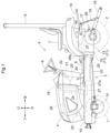
FIG. 1 is a left side view of a tractor. -
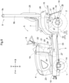
FIG. 2 is a longitudinal front view of a region around a second battery and a motor. -
FIG. 3 schematically shows a system for transmission from the motor to front and rear wheels. -
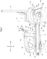
FIG. 4 is a left side view of a tractor according to a second variation of implementation of the present invention. -
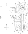
FIG. 5 is a left side view of a tractor according to a third variation of implementation of the present invention. -
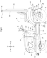
FIG. 6 is a left side view of a tractor according to a fourth variation of implementation of the present invention. -
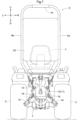
FIG. 7 is a back view of the tractor according to the fourth variation of implementation of the present invention. -
FIG. 8 is a left side view of a tractor according to a fifth variation of implementation of the present invention. -
FIGS. 1 to 8 show electric tractors, each of which is an example of a work vehicle. InFIGS. 1 to 8 , F indicates the forward direction, B indicates the rearward direction, U indicates the upward direction, D indicates the downward direction, R indicates the rightward direction, and L indicates the leftward direction. - As shown in
FIG. 1 , left and right front wheels 1 (each of which corresponds to a front travel device) and left and right rear wheels 2 (each of which corresponds to a rear travel device) support abody 3 of the tractor. Ahood 4 is provided at a front portion of thebody 3, and anoperation section 5 is provided at a rear portion of thebody 3. Theoperation section 5 includes asteering wheel 6 for steering thefront wheels 1, anoperator seat 7, afloor 8, and aROPS frame 9. - The
body 3 has left and right body frames 10, atransmission case 11, and so on. Thetransmission case 11 has afront case 12 and arear case 13 that are joined to each other. The left and right body frames 10 are connected to thetransmission case 11 and extend in the front-back direction below the operation section 5 (floor 8). Thetransmission case 11 is located below theoperator seat 7 in theoperation section 5. - A
front axle case 14 is supported by front portions of the body frames 10, and supports the left and rightfront wheels 1. The transmission case 11 (rear case 13) supports the left and rightrear wheels 2. - A top link 15 (which corresponds to a link mechanism) and left and right lower links 16 (each of which corresponds to a link mechanism) are provided at a rear portion of the transmission case 11 (rear case 13) in such a manner as to be swingable in the up-down direction. The
top link 15 and thelower links 16 can be joined to a work device (not shown), such as a rotary cultivator. - Left and right lift
arms 17 are provided at the rear portion of the transmission case 11 (rear case 13), and a connectingrod 18 is connected to thelift arms 17 and thelower links 16. Thetop link 15 and thelower links 16 are raised and lowered and the work device is raised and lowered by swinging thelift arms 17 in the up-down direction. - As shown in
FIGS. 1 and2 , apillar frame 19 is provided on the body frames 10 between thefront wheels 1 and the operation section 5 (rear wheels 2). Thepillar frame 19 is constituted by a folded plate material and has aright section 19a, aleft section 19b, anupper section 19c, and arear section 19d. - The
rear section 19d of thepillar frame 19 is flat and extends in the up-down direction and the left-right direction. Theright section 19a of thepillar frame 19 is formed by bending forward a right portion of therear section 19d of thepillar frame 19, and extends in the up-down direction and the front-back direction. Theleft section 19b of thepillar frame 19 is formed by bending forward a left portion of therear section 19d of thepillar frame 19, and extends in the up-down direction and the front-back direction. - The
upper section 19c of thepillar frame 19 is formed by bending forward an upper portion of therear section 19d of thepillar frame 19, and extends in the left-right direction and the front-back direction. Theupper section 19c of thepillar frame 19 extends between upper portions of theright section 19a and theleft section 19b of thepillar frame 19. - As shown in
FIG. 1 , thehood 4 is supported such that thehood 4 is openable and closable about a fulcrum in the left-right direction of theupper section 19c of thepillar frame 19, and can be operated from a closed position shown inFIG. 1 to an open position above the closed position. - A
power steering mechanism 20 is provided below a rear face portion of therear section 19d of thepillar frame 19. A steeringpost 21 is attached to thepower steering mechanism 20 and extends upward from thepower steering mechanism 20. Asteering wheel 6 is supported by an upper portion of the steeringpost 21, and a steeringshaft 22 is connected to thesteering wheel 6 and thepower steering mechanism 20. - In response to the
steering wheel 6 being rotated, the rotation of thesteering wheel 6 is transmitted to thepower steering mechanism 20 via the steeringshaft 22, and thepower steering mechanism 20 steers thefront wheels 1 to the left and right. - A
support platform 23 is attached to front upper portions of the left and right body frames 10, as shown inFIGS. 1 and2 . Aninverter 24, which is provided on thesupport platform 23, has a rectangular case with a small dimension (dimension in the front-back direction) that houses various types of equipment. - The
inverter 24 extends in the up-down direction in a side view and extends in the left-right direction in a plan view (front view), and is attached to a rear portion of thesupport platform 23 so as to be in contact with a front face portion of therear section 19d of thepillar frame 19. - The
inverter 24 is provided between theright section 19a and theleft section 19b of thepillar frame 19 in a front view and overlaps theright section 19a and theleft section 19b of thepillar frame 19 in a side view. Theinverter 24 is provided below theupper section 19c of thepillar frame 19 in a front view and overlaps theupper section 19c of thepillar frame 19 in a plan view. - The tractor has a
first battery 25 and asecond battery 26, as shown inFIGS. 1 and2 . Each of thebatteries - The
first battery 25 is disposed between and attached to the left and right body frames 10. A front portion of thefirst battery 25 is located below the pillar frame 119 and below thepower steering mechanism 20, and a rear portion of thefirst battery 25 is close to the transmission case 11 (front case 12). - The
support platform 23 is attached to the front portions of the left and right body frames 10 and located at a position higher than the body frames 10. Thesecond battery 26 is attached to thesupport platform 23. Thesecond battery 26 is provided forward of theinverter 24 and above the body frames 10 and thefront axle case 14. - The
hood 4 at the closed position covers theinverter 24 and thesecond battery 26. Maintenance work on theinverter 24 and thesecond battery 26 can be performed by opening thehood 4. - With the above configuration, the battery 25 (first battery 25) is provided between the front wheels 1 (front travel devices) and the rear wheels 2 (rear travel devices) and below the
floor 8 of theoperation section 5 in a side view, as shown inFIGS. 1 and2 . - The
left body frame 10 and theright body frame 10 extends in the front-back direction below thefloor 8 of theoperation section 5, and the battery 25 (first battery 25) is provided between theleft body frame 10 and theright body frame 10 in a plan view (front view). - The
second battery 26 is supported at a position forward of thefirst battery 25 and above thefirst battery 25. - Left and right mounting brackets 42 are joined to inner faces of the left and right body frames 10, and left and right portions of a
motor 27 are joined to the left and right mounting brackets 42, as shown inFIGS. 1 and2 . - The
motor 27 is provided between thefront wheels 1 and therear wheels 2 and below thesupport platform 23, thesecond battery 26, and theinverter 24 in a side view. Theinverter 24 and thesecond battery 26 are provided above themotor 27 in a side view. - The
inverter 24 converts DC power from thebatteries motor 27 to operate themotor 27. Motive power from themotor 27 is supplied to thefront wheels 1 and therear wheels 2, as shown inFIG. 3 . - A hydrostatic continuously variable transmission 28 (which corresponds to a transmission for travel) is housed within the
front case 12 of thetransmission case 11, as shown inFIGS. 1 ,2 , and3 . Atransmission shaft 29 is connected to anoutput shaft 27a of themotor 27 and aninput shaft 28a of the continuouslyvariable transmission 28, and motive power from themotor 27 is transmitted to the continuouslyvariable transmission 28 via thetransmission shaft 29. The continuouslyvariable transmission 28 is capable of steplessly changing forward and backward and is operated by a gearshift pedal (not shown) on thefloor 8 of theoperation section 5. - An auxiliary transmission 30 (which corresponds to a transmission for travel), a rear wheel
differential device 31, and a front wheel transmission 32 (which corresponds to a transmission for travel) are housed within therear case 13 of thetransmission case 11. Motive power subjected to speed change by the continuouslyvariable transmission 28 is transmitted to theauxiliary transmission 30, and is then transmitted from theauxiliary transmission 30 to therear wheels 2 via the rear wheeldifferential device 31. - Motive power diverted from between the
auxiliary transmission 30 and the rear wheeldifferential device 31 is transmitted to thefront wheel transmission 32. Theoutput shaft 32a of thefront wheel transmission 32 passes through the interior of thefront case 12 of thetransmission case 11 and extends forward from a lower portion of thefront case 12 of thetransmission case 11. - The front wheel
differential device 34 is provided within thefront axle case 14, and aninput shaft 34a of the front wheeldifferential device 34 extends rearward from thefront axle case 14. Atransmission shaft 33 is connected to theoutput shaft 32a of thefront wheel transmission 32 and theinput shaft 34a of the front wheeldifferential device 34. Motive power from thefront wheel transmission 32 is transmitted to the front wheeldifferential device 34 via thetransmission shaft 33, and is then transmitted from the front wheeldifferential device 34 to thefront wheels 1. - The
front wheel transmission 32 drives thefront wheels 1 and therear wheels 2 at the same speed while thefront wheels 1 are operated within the range of left and right set angles from a straight-ahead position. Thefront wheel transmission 32 drives thefront wheels 1 at a higher speed than therear wheels 2 while thefront wheels 1 are steered leftward or rightward beyond the left and right setting angles. - With the above configuration, the tractor has the transmission case 11 (
front case 12 and rear case 13) that houses the continuously variable transmission 28 (transmission for travel), the auxiliary transmission 30 (transmission for travel), and the front wheel transmission 32 (transmission for travel), as shown inFIG. 3 . - Motive power from the
motor 27 is transmitted via thetransmission shaft 29 to the continuously variable transmission 28 (transmission for travel), the auxiliary transmission 30 (transmission for travel), and the front wheel transmission 32 (transmission for travel), and is then transmitted from the continuously variable transmission 28 (transmission for travel), the auxiliary transmission 30 (transmission for travel), and the front wheel transmission 32 (transmission for travel) to the front wheels 1(travel devices) and the rear wheels 2 (travel devices). - The
first battery 25 is provided below theoutput shaft 27a of themotor 27, theinput shaft 28a of the continuouslyvariable transmission 28, and thetransmission shaft 29. Thefirst battery 25 is provided above theoutput shaft 32a of thefront wheel transmission 32, theinput shaft 34a of the front wheeldifferential device 34, and thetransmission shaft 33. - The
transmission shaft 29 extends in the front-back direction above thefirst battery 25 and below thefloor 8, and thetransmission shaft 33 extends in the front-back direction below thefirst battery 25. Thefirst battery 25 is provided between thetransmission shaft 29 and thetransmission shaft 33 in a side view. - A
PTO transmission 35 is housed within therear case 13 of thetransmission case 11, and aPTO shaft 36 is provided at a rear portion of therear case 13 of thetransmission case 11, as shown inFIGS. 1 and3 . A transmission shaft (not shown) is connected to thePTO shaft 36 and the work device in response to the work device being joined to thetop link 15 and thelower links 16. - While motive power from the
motor 27 is transmitted to the continuouslyvariable transmission 28 via thetransmission shaft 29, motive power from the transmission shaft 29 (motive power that is not subjected to speed change by the continuously variable transmission 28) is transmitted to thePTO transmission 35, and motive power subjected to speed change by thePTO transmission 35 is transmitted to thePTO shaft 36 and then transmitted from thePTO shaft 36 to the work device. - A single-acting
hydraulic cylinder 37 is provided above the rear portion of the transmission case 11 (rear case 13), and thehydraulic cylinder 37 raises and lowers thelift arm 17, as shown inFIG. 3 . - A
hydraulic pump 38 and acontrol valve 39 are provided within the rear portion of the transmission case 11 (rear case 13). Lubricating oil that serves as hydraulic oil and stored in the transmission case 11 (rear case 13) is supplied to thehydraulic pump 38, and is then supplied from thehydraulic pump 38 to thecontrol valve 39. - A
pump motor 40 is provided above the rear portion of the transmission case 11 (rear case 13) and drives thehydraulic pump 38. Theinverter 24 converts DC power from thebatteries pump motor 40 to operate thepump motor 40. - Operations to supply and discharge the hydraulic oil to and from the
hydraulic cylinder 37 are performed from thecontrol valve 39, and thehydraulic cylinder 37 raises and lowers thelift arm 17. The hydraulic oil discharged from thehydraulic cylinder 37 is returned fromcontrol valve 39 to the transmission case 11 (rear case 13). - With the above configuration, the
hydraulic cylinder 37, which raises and lowers the top link 15 (link mechanism) and the lower links 16 (link mechanism) to which the work device is joined, and thehydraulic pump 38, which supplies the hydraulic oil to thehydraulic cylinder 37, are provided in the transmission case 11 (rear case 13), as shown inFIGS. 1 and3 . - The
pump motor 40, which drives thehydraulic pump 38, is located between theoperator seat 7 in theoperation section 5 and the transmission case 11 (rear case 13) in a side view. - In the configuration shown in
FIGS. 1 and2 , themotor 27 may be joined to thesupport platform 23 and supported by thebody 3. Themotor 27 may be joined to thepillar frame 19 and supported by thebody 3. - In the configuration shown in
FIGS. 1 and2 , theinverter 24 may be joined to thepillar frame 19 and supported by thebody 3. Theinverter 24 may be provided forward of thesecond battery 26 in a side view. - If the
battery 25 is disposed between and attached to the left and right body frames 10, thebattery 25 may have a larger capacity and be provided such that the front portion of thebattery 25 is located above thefront axle case 14 and the rear portion of thebattery 25 is located close to the transmission case 11 (front case 12), as shown inFIG. 4 . - The second battery 26 (see
FIG. 1 ) may be eliminated, as shown inFIG. 4 . Themotor 27 need only be provided forward of the front axle case 14 (front wheels 1 (front travel devices)) in a side view since the front portion of thebattery 25 is located above thefront axle case 14. - According to the configuration shown in
FIG. 4 , themotor 27 is disposed at a lower position. Thus, atransmission mechanism 41 of a gear transmission type need only be attached to theoutput shaft 27a of themotor 27 and extend upward from themotor 27. Thetransmission shaft 29 need only be connected to anoutput shaft 41a at an upper portion of thetransmission mechanism 41 and theinput shaft 28a of the continuously variable transmission 28 (seeFIG. 3 ) and extend in the front-back direction above thefront axle case 14 and thebattery 25 and below thefloor 8. - Motive power from the
output shaft 27a of themotor 27 is transmitted to thetransmission mechanism 41, then from theoutput shaft 41a oftransmission mechanism 41 to the continuously variable transmission 28 (seeFIG. 3 ) via thetransmission shaft 29, and is transmitted to thefront wheels 1 and therear wheels 2. - According to the configuration shown in
FIG. 4 , themotor 27 is disposed at a lower position. Thus, thesupport platform 23 may be configured to be lower and theinverter 24 may be attached to thesupport platform 23 along the horizontal direction. - If the
inverter 24 is attached to thesupport platform 23 in the horizontal direction, thehood 4 need only be configured such that the front portion of thehood 4 is lower, and the upper portion of thehood 4 need only extend diagonally forward and downward from theupper section 19c of thepillar frame 19 in a side view. This provides a wide forward and downward view for an operator sitting in theoperator seat 7 in theoperation section 5. - In the configuration shown in
FIG. 4 , themotor 27 may be joined to thesupport platform 23 and supported by thebody 3. Theinverter 24 may be joined to thepillar frame 19 in the up-down direction and supported by thebody 3, as shown inFIG. 1 . - If the transmission case 11 (
front case 12 and rear case 13) is provided below theoperator seat 7 in theoperation section 5, thebattery 25 may be attached to an upper portion of the transmission case 11 (front case 12 and rear case 13) and provided between theoperator seat 7 in theoperation section 5 and the transmission case 11 (front case 12 and rear case 13) in a side view, as shown inFIG. 5 . - In the configuration shown in
FIG. 5 , if the pump motor 40 (seeFIG. 1 ) is attached to a left or right side portion of the transmission case 11 (rear case 13), thebattery 25 can be attached to the upper portion of the transmission case 11 (front case 12 and rear case 13) without difficulty. - The second battery 26 (see
FIG. 1 ) may be eliminated. If thebattery 25 alone has insufficient capacity, thesecond battery 26 may also be attached to thesupport platform 23 as shown inFIG. 1 . - If the
second battery 26 is eliminated, thehood 4 need only be configured such that the front portion of thehood 4 is lower, and the upper portion of thehood 4 need only extend diagonally forward and downward from theupper section 19c of thepillar frame 19 in a side view. This provides a wide forward and downward view for an operator sitting in theoperator seat 7 in theoperation section 5. - According to the configuration shown in
FIG. 5 , thebattery 25 is not provided between the left and right body frames 10. Thus, themotor 27 can be disposed at a position lower than the position shown inFIG. 1 . This allows thesupport platform 23 to be configured to be lower and the position of theinverter 24 to be lower than the position shown inFIG. 1 . - In the configuration shown in
FIG. 5 , theinverter 24 may be attached to thesupport platform 23 in the horizontal direction, as shown inFIG. 4 . - The
battery 25 may be provided on theROPS frame 9 located rearward of theoperator seat 7, as shown inFIGS. 6 and7 . - The
ROPS frame 9 is constituted by a bent square pipe, and has aright section 9a, aleft section 9b, and anupper section 9c. - The
right section 9a of theROPS frame 9 extends in the up-down direction, and a lower portion of theright section 9a of theROPS frame 9 is joined to the transmission case 11 (rear case 13). Theleft section 9b of theROPS frame 9 extends in the up-down direction, and a lower portion of theleft section 9b of theROPS frame 9 is joined to the transmission case 11 (rear case 13). Theupper section 9c of theROPS frame 9 extends in the left-right direction and is joined to an upper portion of theright section 9a and an upper portion of theleft section 9b of theROPS frame 9. - The
battery 25 is configured to be small in the dimension in the front-back direction, disposed between theright section 9a and theleft section 9b of theROPS frame 9 in a back view (front view), and joined to theright section 9a and theleft section 9b of theROPS frame 9. - The
battery 25 extends in the up-down direction and the left-right direction behind theoperator seat 7 in theoperation section 5. Thebattery 25 overlaps theright section 9a and theleft section 9b of theROPS frame 9 in a side view, and overlaps theupper section 9c of theROPS frame 9 in a plan view. - The second battery 26 (see
FIG. 1 ) may be eliminated, as shown inFIGS. 6 and7 . A headrest (not shown) may also be attached to a portion of the front face of thebattery 25 above of theoperator seat 7. - If the
first battery 25 is provided on theROPS frame 9, thesecond battery 26 may be attached to the upper portion of the transmission case 11 (front case 12 and rear case 13) and provided between theoperator seat 7 in theoperation section 5 and the transmission case 11 (front case 12 and rear case 13) in a side view, as shown inFIG. 8 . - The
first battery 25 is disposed between theright section 9a and theleft section 9b of theROPS frame 9 in a back view (front view) and connected to theright section 9a and theleft section 9b of theROPS frame 9, as in the configuration shown inFIGS. 6 and7 . Thefirst battery 25 extends in the up-down direction and the left-right direction behind theoperator seat 7 in theoperation section 5. Thefirst battery 25 overlaps theright section 9a and theleft section 9b of theROPS frame 9 in a side view, and overlaps theupper section 9c of theROPS frame 9 in a plan view. - If the first and
second batteries first battery 25 can be configured to be shorter than thebattery 25 shown inFIGS. 6 and7 , as shown inFIG. 8 .
In the configuration shown inFIG. 8 , a headrest (not shown) may also be attached to an upper portion of thefirst battery 25. Theinverter 24 may be attached to thesupport platform 23 in the horizontal direction, as shown inFIG. 4 . - If the pump motor 40 (see
FIG. 1 ) in the configuration shown inFIG. 8 is attached to a left or right side portion of the transmission case 11 (rear case 13), thesecond battery 26 can be attached to the upper portion of the transmission case 11 (front case 12 and rear case 13) without difficulty. - If the tractor has the first and
second batteries first battery 25 is provided on theROPS frame 9, thesecond battery 26 may be provided between the left and right body frames 10, as shown inFIG. 1 . Thesecond battery 26 may be attached to thesupport platform 23, as shown inFIG. 1 . Thesecond battery 26 may be provided both between the left and right body frames 10 and at thesupport platform 23. - If the
second battery 26 is provided forward of theoperation section 5 as shown inFIG. 1 , theinverter 24 may be provided forward of thesecond battery 26. - According to this configuration, the
inverter 24 extends in the up-down direction in a side view and extends in the left-right direction in a plan view (front view), and is provided between a front portion of thehood 4 and a front portion of thesecond battery 26. - In the configuration shown in any of
FIGS. 1 ,4 ,5 ,6 , and8 , themotor 27 may be provided above the front axle case 14 (front wheels 1 (front travel devices)) in a side view. Themotor 27 in this configuration may be joined to thesupport platform 23 and supported by thebody 3. - In the configuration shown in any of
FIGS. 1 ,5 ,6 and8 , themotor 27 may be provided forward of the front axle case 14 (front wheels 1 (front travel devices)) in a side view, as shown inFIG. 4 . - In the configuration shown in any of
FIGS. 1 ,4 ,5 ,6 , and8 , themotor 27 may be attached to the upper portion of the transmission case 11 (front case 12 and rear case 13), and may be provided between theoperator seat 7 in theoperation section 5 and the transmission case 11 (front case 12 and rear case 13) in a side view. - In the configuration shown in any of
FIGS. 1 ,4 ,5 ,6 , and8 , theinverter 24 may be provided between theoperator seat 7 in theoperation section 5 and the transmission case 11 (front case 12 and rear case 13) in a side view by attaching theinverter 24 to a support frame (not shown) that is provided in theoperation section 5 to support theoperator seat 7. - In the case of the
ROPS frame 9 that is constituted by a square pipe material, thefirst battery 25 may be provided inward of the square pipe of theROPS frame 9. - According to this configuration, the
first battery 25 is not exposed to the outside of theROPS frame 9, thus allowing for good rearward visibility for the operator sitting in theoperator seat 7. Thesecond battery 26 need only be provided between theoperator seat 7 in theoperation section 5 and the transmission case 11 (front case 12 and rear case 13) to ensure the overall capacity of thebatteries - The
ROPS frame 9 may be provided in an area corresponding to thepillar frame 19 in a side view, rather than being provided rearward of theoperator seat 7, and theROPS frame 9 may be provided forward of thesteering wheel 6. - The tractor may have a four-wheel steering structure in which the
front wheels 1 and therear wheels 2 are steered in the same and opposite phases by thesteering wheel 6. - Crawler-type travel devices (not shown) may be provided instead of the
front wheels 1 as the front travel devices. Crawler-type travel devices (not shown) may be provided instead of therear wheels 2 as the rear travel devices. One crawler-type travel device (not shown) may be provided instead of thefront wheels 1 and therear wheels 2. - The first and
second batteries support platform 23 and located inside thehood 4. - The present invention can be applied to not only electric tractors in which a motor drives a travel device, but also to hybrid tractors in which an engine and a motor drive a travel device, and can be applied to not only tractors but also construction work vehicles and agricultural work vehicles.
-
- 1
- Front wheel (travel device)
- 2
- Rear wheel (travel device)
- 5
- Operation section
- 7
- Operator seat
- 8
- Floor
- 9
- ROPS frame
- 10
- Body frame
- 11
- Transmission case
- 15
- Top link (link mechanism)
- 16
- Lower link (link mechanism)
- 24
- Inverter
- 25
- Battery
- 26
- Battery
- 27
- Motor
- 28
- Continuously variable transmission (transmission for travel)
- 30
- Auxiliary transmission (transmission for travel)
- 32
- Front wheel transmission (transmission for travel)
- 37
- Hydraulic cylinder
- 38
- Hydraulic pump
- 40
- Pump motor
Claims (7)
- A work vehicle comprising:travel devices including a front travel device (1) and a rear travel device (2);at least one battery (25,26);a motor (27) configured to supply motive power to the travel devices;an inverter (24) configured to operate the motor; anda transmission case (11) housing a transmission for travelan operation section (5) having a floor (8) and including an operator seat (7),wherein the at least one battery (25,26) is between the front travel device (1) and the rear travel device (2) in a side view and below the floor of the operation section.
- The work vehicle according to claim 1, further comprising:a left body frame and a right body frame (10) that extend in a front-back direction below the floor,wherein the at least one battery (25,26) is between the left body frame and the right body frame in a plan view.
- The work vehicle according to claim 1 or 2,wherein the at least one battery includes a first battery (25) and a second battery (25),the first battery is between the front travel device (1) and the rear travel device (2) in a side view and below the floor (8), andthe second battery (26) is supported at a position forward of the first battery and above the first battery.
- A work vehicle comprising:a travel device (1,2);a battery (25,26);a motor (27);an inverter (24) configured to operate the motor;an operation section (5) including an operator seat (7); anda transmission case (11) housing a transmission for travel (28),wherein the motor (27), the transmission (28), and the travel device (1,2) are configured such that motive power from the motor is transmitted to the transmission and transmitted from the transmission to the travel device,the transmission case is below the operator seat, andthe battery is between the operator seat and the transmission case in a side view.
- A work vehicle comprising:a travel device (1,2);at least one battery (25,26);a motor (27) configured to supply motive power to the travel device;an inverter (24) configured to operate the motor;a transmission case (11) housing a transmission for travel an operation section (5) including an operator seat (7); anda ROPS frame (9),wherein the at least one battery is on the ROPS frame.
- The work vehicle according to claim 5,wherein the at least one battery includes a first battery (25) and a second battery (26),the transmission case (11) is below the operator seat (5),the motor (27), the transmission (28), and the travel device (1,2) are configured such that motive power from the motor is transmitted to the transmission and transmitted from the transmission to the travel device,the first battery (25) is on the ROPS frame, andthe second battery (26) is between the operator seat (5) and the transmission case (11) in a side view.
- The work vehicle according to any one of claims 1, 2, 4, 5, and 6, further comprising:a work device;a link mechanism (15,16) disposed on the transmission case (11), configured to be raised and lowered, and joined to the work device;a hydraulic cylinder (37) disposed on the transmission case and configured to raise and lower the link mechanism;a hydraulic pump (38) configured to supply hydraulic oil to the hydraulic cylinder; anda pump motor (40) configured to drive the hydraulic pump,wherein the motor (27), the transmission (28), and the travel devices (1,2) are configured such that motive power from the motor is transmitted to the transmission and transmitted from the transmission to the travel devices,the transmission case (11) is below the operator seat (5), andthe pump motor (40) is between the operator seat and the transmission case in a side view.
Applications Claiming Priority (1)
| Application Number | Priority Date | Filing Date | Title |
|---|---|---|---|
| JP2022152769A JP7792880B2 (en) | 2022-09-26 | 2022-09-26 | Work vehicle |
Publications (1)
| Publication Number | Publication Date |
|---|---|
| EP4342704A1 true EP4342704A1 (en) | 2024-03-27 |
Family
ID=88197093
Family Applications (1)
| Application Number | Title | Priority Date | Filing Date |
|---|---|---|---|
| EP23199486.4A Pending EP4342704A1 (en) | 2022-09-26 | 2023-09-25 | Work vehicle |
Country Status (3)
| Country | Link |
|---|---|
| US (1) | US12139026B2 (en) |
| EP (1) | EP4342704A1 (en) |
| JP (1) | JP7792880B2 (en) |
Families Citing this family (2)
| Publication number | Priority date | Publication date | Assignee | Title |
|---|---|---|---|---|
| CN119451840A (en) * | 2022-06-28 | 2025-02-14 | 株式会社久保田 | Work vehicles |
| JPWO2024004914A1 (en) * | 2022-06-28 | 2024-01-04 |
Citations (4)
| Publication number | Priority date | Publication date | Assignee | Title |
|---|---|---|---|---|
| JP2013141875A (en) | 2012-01-10 | 2013-07-22 | Kubota Corp | Electric tractor |
| US20210053435A1 (en) * | 2019-08-20 | 2021-02-25 | Kanzaki Kokyukoki Mfg. Co., Ltd. | Hybrid vehicle |
| WO2021131249A1 (en) * | 2019-12-26 | 2021-07-01 | 株式会社クボタ | Electric work vehicle |
| EP3988366A1 (en) * | 2019-06-24 | 2022-04-27 | Kubota Corporation | Electric work vehicle |
Family Cites Families (19)
| Publication number | Priority date | Publication date | Assignee | Title |
|---|---|---|---|---|
| US5921338A (en) * | 1997-08-11 | 1999-07-13 | Robin L. Edmondson | Personal transporter having multiple independent wheel drive |
| JP2002186110A (en) | 2000-12-18 | 2002-06-28 | Yanmar Agricult Equip Co Ltd | Agricultural working machine with hybrid system |
| JP3713480B2 (en) | 2002-11-19 | 2005-11-09 | 日立建機株式会社 | Electric drive wheeled work vehicle |
| JP4225078B2 (en) | 2003-02-24 | 2009-02-18 | トヨタ車体株式会社 | Equipment for loading hydrogen cylinders for vehicles |
| US8033899B2 (en) * | 2005-08-31 | 2011-10-11 | Kubota Corporation | Cabin for a work vehicle |
| JP4376874B2 (en) * | 2006-05-17 | 2009-12-02 | トヨタ自動車株式会社 | Power supply device and vehicle |
| JP5474737B2 (en) * | 2010-11-11 | 2014-04-16 | 本田技研工業株式会社 | Saddle riding type electric vehicle |
| US8616310B2 (en) * | 2011-01-14 | 2013-12-31 | Gilbert T. Lopez | Apparatus for farming, gardening and landscaping |
| JP5379821B2 (en) | 2011-03-30 | 2013-12-25 | 株式会社クボタ | Work vehicle |
| KR101302262B1 (en) * | 2011-03-30 | 2013-09-02 | 가부시끼 가이샤 구보다 | Working car |
| US10717361B2 (en) * | 2016-01-19 | 2020-07-21 | Kubota Corporation | Work vehicle and display device for the work vehicle |
| JP2017165262A (en) * | 2016-03-16 | 2017-09-21 | 株式会社クボタ | Work vehicle |
| US10724618B2 (en) | 2018-03-21 | 2020-07-28 | Deere & Company | Electric drive axle system |
| JP7304750B2 (en) * | 2019-06-24 | 2023-07-07 | 株式会社クボタ | electric work vehicle |
| JP7359421B2 (en) | 2019-08-20 | 2023-10-11 | 株式会社 神崎高級工機製作所 | hybrid vehicle |
| JP7150081B1 (en) * | 2021-03-29 | 2022-10-07 | 株式会社クボタ | work vehicle |
| JP7741030B2 (en) * | 2022-06-03 | 2025-09-17 | 株式会社クボタ | Work vehicle |
| JP7792881B2 (en) * | 2022-09-26 | 2025-12-26 | 株式会社クボタ | Work vehicle |
| JP7788980B2 (en) * | 2022-09-26 | 2025-12-19 | 株式会社クボタ | Work vehicle |
-
2022
- 2022-09-26 JP JP2022152769A patent/JP7792880B2/en active Active
-
2023
- 2023-09-25 EP EP23199486.4A patent/EP4342704A1/en active Pending
- 2023-09-25 US US18/372,360 patent/US12139026B2/en active Active
Patent Citations (4)
| Publication number | Priority date | Publication date | Assignee | Title |
|---|---|---|---|---|
| JP2013141875A (en) | 2012-01-10 | 2013-07-22 | Kubota Corp | Electric tractor |
| EP3988366A1 (en) * | 2019-06-24 | 2022-04-27 | Kubota Corporation | Electric work vehicle |
| US20210053435A1 (en) * | 2019-08-20 | 2021-02-25 | Kanzaki Kokyukoki Mfg. Co., Ltd. | Hybrid vehicle |
| WO2021131249A1 (en) * | 2019-12-26 | 2021-07-01 | 株式会社クボタ | Electric work vehicle |
Also Published As
| Publication number | Publication date |
|---|---|
| US12139026B2 (en) | 2024-11-12 |
| JP7792880B2 (en) | 2025-12-26 |
| JP2024047247A (en) | 2024-04-05 |
| US20240100971A1 (en) | 2024-03-28 |
Similar Documents
| Publication | Publication Date | Title |
|---|---|---|
| US12139026B2 (en) | Work vehicle | |
| CN110626992A (en) | Work vehicle with electric energy accumulator | |
| WO2021131249A1 (en) | Electric work vehicle | |
| NL1035694C2 (en) | Mobile apparatus for use in e.g. agriculture has automatically movable lifting device that is provided on the main frame and is adapted to be connectable to the agricultural attachment | |
| US20060073003A1 (en) | Front loader attachment construction and work vehicle having the attachment construction | |
| EP4344922A1 (en) | Work vehicle | |
| EP4342707A1 (en) | Work vehicle | |
| CN1110424C (en) | Vehicle having lifting arm, which can be used as agricultural machine | |
| EP3299264B1 (en) | Crawler tractor | |
| JP5658019B2 (en) | Farm tractor | |
| WO2023119888A1 (en) | Electric work vehicle | |
| CN212164138U (en) | Agricultural Power Machinery | |
| US20220339979A1 (en) | Tractor | |
| EP4397517A1 (en) | Electric work vehicle | |
| JP2000053032A (en) | Tractor | |
| JPH11334395A (en) | Tractor transmission | |
| JP2006025737A (en) | Aircraft structure of tractor | |
| JP2023095631A (en) | electric work vehicle | |
| JP5643734B2 (en) | Tractor | |
| JP2026036974A (en) | Work vehicles | |
| JPS6235339Y2 (en) | ||
| JP3583590B2 (en) | Tractor hydraulic lifting device | |
| CN111436241A (en) | Agricultural Power Machinery | |
| JP2007308065A (en) | Working machine | |
| JPH03200423A (en) | Transmission structure of manned operating machine |
Legal Events
| Date | Code | Title | Description |
|---|---|---|---|
| PUAI | Public reference made under article 153(3) epc to a published international application that has entered the european phase |
Free format text: ORIGINAL CODE: 0009012 |
|
| STAA | Information on the status of an ep patent application or granted ep patent |
Free format text: STATUS: REQUEST FOR EXAMINATION WAS MADE |
|
| 17P | Request for examination filed |
Effective date: 20230925 |
|
| AK | Designated contracting states |
Kind code of ref document: A1 Designated state(s): AL AT BE BG CH CY CZ DE DK EE ES FI FR GB GR HR HU IE IS IT LI LT LU LV MC ME MK MT NL NO PL PT RO RS SE SI SK SM TR |