EP4342570A1 - Wechselkartusche - Google Patents
Wechselkartusche Download PDFInfo
- Publication number
- EP4342570A1 EP4342570A1 EP23190169.5A EP23190169A EP4342570A1 EP 4342570 A1 EP4342570 A1 EP 4342570A1 EP 23190169 A EP23190169 A EP 23190169A EP 4342570 A1 EP4342570 A1 EP 4342570A1
- Authority
- EP
- European Patent Office
- Prior art keywords
- expansion tank
- cartridge
- return valve
- opening
- flow path
- Prior art date
- Legal status (The legal status is an assumption and is not a legal conclusion. Google has not performed a legal analysis and makes no representation as to the accuracy of the status listed.)
- Pending
Links
Images

Classifications
-
- B—PERFORMING OPERATIONS; TRANSPORTING
- B01—PHYSICAL OR CHEMICAL PROCESSES OR APPARATUS IN GENERAL
- B01D—SEPARATION
- B01D53/00—Separation of gases or vapours; Recovering vapours of volatile solvents from gases; Chemical or biological purification of waste gases, e.g. engine exhaust gases, smoke, fumes, flue gases, aerosols
- B01D53/26—Drying gases or vapours
- B01D53/261—Drying gases or vapours by adsorption
-
- B—PERFORMING OPERATIONS; TRANSPORTING
- B01—PHYSICAL OR CHEMICAL PROCESSES OR APPARATUS IN GENERAL
- B01D—SEPARATION
- B01D53/00—Separation of gases or vapours; Recovering vapours of volatile solvents from gases; Chemical or biological purification of waste gases, e.g. engine exhaust gases, smoke, fumes, flue gases, aerosols
- B01D53/02—Separation of gases or vapours; Recovering vapours of volatile solvents from gases; Chemical or biological purification of waste gases, e.g. engine exhaust gases, smoke, fumes, flue gases, aerosols by adsorption, e.g. preparative gas chromatography
- B01D53/04—Separation of gases or vapours; Recovering vapours of volatile solvents from gases; Chemical or biological purification of waste gases, e.g. engine exhaust gases, smoke, fumes, flue gases, aerosols by adsorption, e.g. preparative gas chromatography with stationary adsorbents
- B01D53/0407—Constructional details of adsorbing systems
- B01D53/0415—Beds in cartridges
-
- B—PERFORMING OPERATIONS; TRANSPORTING
- B01—PHYSICAL OR CHEMICAL PROCESSES OR APPARATUS IN GENERAL
- B01D—SEPARATION
- B01D53/00—Separation of gases or vapours; Recovering vapours of volatile solvents from gases; Chemical or biological purification of waste gases, e.g. engine exhaust gases, smoke, fumes, flue gases, aerosols
- B01D53/02—Separation of gases or vapours; Recovering vapours of volatile solvents from gases; Chemical or biological purification of waste gases, e.g. engine exhaust gases, smoke, fumes, flue gases, aerosols by adsorption, e.g. preparative gas chromatography
- B01D53/04—Separation of gases or vapours; Recovering vapours of volatile solvents from gases; Chemical or biological purification of waste gases, e.g. engine exhaust gases, smoke, fumes, flue gases, aerosols by adsorption, e.g. preparative gas chromatography with stationary adsorbents
- B01D53/0407—Constructional details of adsorbing systems
- B01D53/0431—Beds with radial gas flow
-
- B—PERFORMING OPERATIONS; TRANSPORTING
- B01—PHYSICAL OR CHEMICAL PROCESSES OR APPARATUS IN GENERAL
- B01D—SEPARATION
- B01D2257/00—Components to be removed
- B01D2257/70—Organic compounds not provided for in groups B01D2257/00 - B01D2257/602
- B01D2257/702—Hydrocarbons
-
- B—PERFORMING OPERATIONS; TRANSPORTING
- B01—PHYSICAL OR CHEMICAL PROCESSES OR APPARATUS IN GENERAL
- B01D—SEPARATION
- B01D2259/00—Type of treatment
- B01D2259/45—Gas separation or purification devices adapted for specific applications
- B01D2259/4525—Gas separation or purification devices adapted for specific applications for storage and dispensing systems
-
- H—ELECTRICITY
- H01—ELECTRIC ELEMENTS
- H01M—PROCESSES OR MEANS, e.g. BATTERIES, FOR THE DIRECT CONVERSION OF CHEMICAL ENERGY INTO ELECTRICAL ENERGY
- H01M10/00—Secondary cells; Manufacture thereof
- H01M10/60—Heating or cooling; Temperature control
- H01M10/61—Types of temperature control
- H01M10/613—Cooling or keeping cold
-
- H—ELECTRICITY
- H01—ELECTRIC ELEMENTS
- H01M—PROCESSES OR MEANS, e.g. BATTERIES, FOR THE DIRECT CONVERSION OF CHEMICAL ENERGY INTO ELECTRICAL ENERGY
- H01M10/00—Secondary cells; Manufacture thereof
- H01M10/60—Heating or cooling; Temperature control
- H01M10/62—Heating or cooling; Temperature control specially adapted for specific applications
- H01M10/625—Vehicles
Definitions
- the present invention relates to a removable cartridge and a compensation container for a dielectric coolant with such a removable cartridge.
- the invention also relates to a cooling system for a battery arrangement with such an expansion tank and an electric vehicle with a battery arrangement and such a cooling system.
- drying devices filter devices and adsorber devices such as activated carbon filters are used.
- the disadvantage of these systems is that they are connected separately to a corresponding one Expansion tanks for a dielectric coolant must be attached and controlled via appropriate valve devices.
- the present invention therefore deals with the problem of specifying a removable cartridge which, in particular, overcomes the disadvantages known from the prior art.
- the present invention is based on the general idea of specifying a replaceable cartridge in which a filter device, a drying device and a hydrocarbon adsorber device are integrated.
- the interchangeable cartridge according to the invention is used to clean and dry (balancing) air and has a housing in which a first flow path with a filter device and a drying device and an oppositely directed second flow path with a hydrocarbon adsorber device run.
- Such a replaceable cartridge can, for example, be screwed comparatively easily to an expansion tank for a dielectric coolant of a cooling system for a battery arrangement using a screw cap, with the integrated filter device preventing contaminants present in the environment from getting into the coolant.
- the drying device can also be used to reduce the water content of air entering the expansion tank from the environment, for example due to temperature-related volume fluctuations, or lower it to a predefined limit value, which can reliably prevent the functionality of the coolant from being impaired or due to a If the water content is too high, it may even become electrically conductive, which in the worst case scenario could lead to a short circuit.
- the first flow path therefore leads from an environment into the expansion tank, while the second flow path leads from the expansion tank into the environment.
- the hydrocarbon adsorber device is arranged in the second flow path, which adsorbs volatile hydrocarbon components and therefore does not allow them to escape into the environment.
- Valve devices in particular check valves, are of course also arranged between the replaceable cartridge and the expansion tank, which allow a flow in the first flow path exclusively from the environment into the expansion tank and in the second flow path exclusively from the expansion tank into the environment.
- the interchangeable cartridge has an internal thread at an entrance of the second flow path for screwing onto an expansion tank for coolant, the hydrocarbon adsorber device being arranged coaxially to an axis of the interchangeable cartridge.
- the hydrocarbon adsorber device has, for example, activated carbon, which is not only inexpensive but also regenerable.
- the filter device is designed as a folded star coaxially surrounding the hydrocarbon adsorber device.
- a wrinkle star is for It is well known for filtration purposes and offers a comparatively large surface area for filtering dirt particles, for example.
- the drying device surrounds the hydrocarbon adsorber device and the filter device in turn coaxially. The air flowing from the environment into the expansion tank in the first flow path first flows through the filter device and is cleaned there of, for example, contaminants. It then flows through the drying device, which reduces the water content. Due to the coaxial arrangement of the filter device and the drying device, a flow path running in a known manner in conventional filter devices can be realized.
- the drying device has a molecular sieve.
- a molecular sieve can, for example, contain synthetic zeolites or other substances that have a high adsorption capacity for gases, vapors and/or dissolved substances with certain molecular sizes.
- the housing of the removable cartridge expediently has a lid and a base.
- a first opening is arranged in the cover of the housing, while a laterally arranged second opening and a centrally arranged third opening are provided in the base.
- the first flow path runs from the first to the second opening, while the second flow path runs from the third opening to the first opening.
- a moisture sensor is arranged on a dry side of the drying device. This makes it possible to detect the humidity of air entering, for example, an expansion tank for dielectric coolant and, if this is exceeded, to generate a corresponding warning signal, which prompts the replacement cartridge to be replaced.
- a hydrocarbon sensor can be arranged in the area of the hydrocarbon adsorber device, which is arranged in particular on the outlet side of the second flow path and the hydrocarbon adsorber device.
- the present invention is further based on the general idea of providing an expansion tank for a dielectric coolant, with a removable cartridge according to the previous paragraphs.
- a first non-return valve which is permeable from the environment to the equalizing container, and a second non-return valve, which is permeable from the equalizing container to the hydrocarbon adsorber device, is arranged between the equalization container and the replaceable cartridge.
- the first non-return valve only opens when there is a predefined pressure difference between an interior of the expansion tank and the surroundings.
- the first non-return valve and the second non-return valve are expediently arranged on the expansion tank. This offers the great advantage that when the replaceable cartridge is replaced, for example due to a loaded hydrocarbon adsorber device, only the replaceable cartridge has to be disposed of, but the two non-return valves can continue to be used unchanged. Alternatively, it is also purely theoretically conceivable that the first non-return valve and the second non-return valve are arranged on the replaceable cartridge.
- a connector with an external thread is arranged on it, the second non-return valve being arranged in the connector.
- the interchangeable cartridge has an internal thread that is complementary to the external thread arranged on the nozzle, via which it can be screwed to the expansion tank.
- the hydrocarbon adsorber device is arranged coaxially to the axis of the replaceable cartridge and to the connection of the expansion tank.
- a connector with an internal thread can also be arranged on the expansion tank according to the invention, with the second non-return valve being arranged in the connector.
- the interchangeable cartridge has an external thread that is complementary to the internal thread arranged on the nozzle, via which it can be screwed to the expansion tank.
- a bayonet lock or a clip connection can also be provided to fix the removable cartridge on the expansion tank.
- the housing of the interchangeable cartridge has an edge which, when the interchangeable cartridge is arranged on the expansion tank, rests tightly against it and, together with the housing of the interchangeable cartridge and the expansion tank, delimits a ventilation space which has the second opening in the housing
- Exchangeable cartridge is connected to a dry side of the drying device and via the first non-return valve to an interior of the expansion tank.
- the edge of the removable cartridge is placed on the expansion tank, which results in the ventilation space that is closed to the outside.
- the present invention is further based on the general idea of equipping a cooling system for a battery assembly with an expansion tank described in the previous paragraphs.
- a cooling system can be installed in an electric vehicle, for example. This makes it possible to prevent unwanted entry of water and dirt from the environment into the expansion tank as well as undesirable discharge of hydrocarbons from the expansion tank into the environment.
- By integrating the filter device, the drying device and the hydrocarbon adsorber device into the interchangeable cartridge comparatively simple maintenance can also be carried out by simply replacing the interchangeable cartridge. This can be achieved particularly cost-effectively if the first and second non-return valves are arranged on the expansion tank.
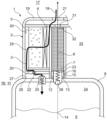
- an interchangeable cartridge 1 for cleaning and drying air has a housing 2 in which a first flow path 3 with a filter device 4, in particular a ring filter, and a drying device 5 is arranged. Also provided is a second flow path 6 running opposite to the first flow path 3 with a hydrocarbon adsorber device 7.
- the interchangeable cartridge 1 is in accordance with that Figure 1 For the sake of clarity, it is only shown in its left half.
- the replacement cartridge 1 can, for example, be arranged, in particular screwed, on a compensation container 8 for dielectric coolant 9, such a compensation container 8 with the replacement cartridge 1 screwed thereto, for example being inserted or used in a cooling system 10 for a battery arrangement 33 in an electric vehicle 11 can.
- the interchangeable cartridge 1 has an internal thread 3 at an entrance 12 of the second flow path 6 for screwing onto the expansion tank 8, the hydrocarbon adsorber device 7 being arranged coaxially to an axis 14 of the interchangeable cartridge 1.
- the axis 14 also designates the screw axis.
- the expansion tank 8 has an external thread 15 on a connector 16 that is complementary to the internal thread 13, which enables a comparatively simple installation of the interchangeable cartridge 1 on the expansion tank 8 by simply screwing it on.
- connection 16 with an internal thread can also be arranged on the expansion tank 8 according to the invention, with a second return check valve 26 being arranged in the connection 16.
- the interchangeable cartridge 1 has an external thread that is complementary to the internal thread arranged on the connector 16, via which it can be screwed to the expansion tank 8.
- a bayonet lock (not shown) or a clip connection can also be provided for fixing the removable cartridge 1 to the expansion tank 8. Regardless of the respective connection mechanism, a quick and easy change of the removable cartridge 1 as well as a reliable prevention of undesired leakage of hydrocarbons are made possible.
- the filter device 4 can be designed as a folded star coaxially surrounding the hydrocarbon adsorber device 7, which results in a comparatively large filter area in a comparatively small installation space. In this way, flow resistance in particular can be kept small and filtration performance high.
- the drying device 5 surrounds the hydrocarbon adsorber device 7 and in the present case also the filter device 4 coaxially, so that air 18 flowing from an environment 17 via the first flow path 3 through the replaceable cartridge 1 first flows through the filter device 4 and then the drying device 5, whereby the air 18 initially flows through is freed from contaminants in the filter device 4 and then from water components in the drying device 5.
- the drying device 5 can, for example, have a molecular sieve, in particular a zeolite.
- the housing 2 of the removable cartridge 1 has a cover 19 and a base 20, which can be designed to be separate and connectable to one another, but which can alternatively also be designed in one piece.
- There is one in the lid 19 first opening 21 is arranged, while a second opening 22 is arranged in the bottom 20.
- a third opening 23 is also provided centrally in the base 20.
- the first flow path 3 runs from the first opening 21 to the second opening 22, while the second flow path 6 runs from the third opening 23 to the first opening 21.
- An exchange between an interior 24 of the expansion tank 8 and the environment 17 usually only takes place when volume fluctuations in the dielectric coolant 9 require it, for example due to temperature changes.
- a first non-return valve 25 and the second non-return valve 26 are provided, the first non-return valve being permeable from the environment 17 into the interior 24 of the expansion tank 8, while the second non-return valve 26 is permeable in the opposite direction .
- a corresponding excess pressure or negative pressure is required.
- both the first non-return valve 25 and the second non-return valve 26 are arranged on the expansion tank 8, which means that the replacement cartridge 1 can be replaced without any problems and the latter can also be produced inexpensively.
- an alternative embodiment is of course also conceivable, in which the first non-return valve 25 and the second non-return valve 26 are arranged on the replaceable cartridge 1.
- the second non-return valve 26 is arranged in the connection piece 16.
- the housing 2 of the interchangeable cartridge 1 has an edge 27 which lies tightly against the interchangeable cartridge 1 arranged on the expansion tank 8 and together with the housing 2 of the removable cartridge 1 and the expansion tank 8 or its housing, a ventilation space 28 delimits, which via the second opening 22 in the housing 2 of the removable cartridge 1 with a dry side 29 of the drying device 5 and via the first non-return valve 25 with the interior 24 of the expansion tank 8 is connected.
- the edge 27 thus enables the ventilation space 28 to be delimited and the second opening 22 to be connected to the first return check valve 25 regardless of the angle of rotation.
- a moisture sensor 30 can also be arranged to detect a water content of the air to be supplied to the expansion tank 8.
- a hydrocarbon sensor 32 can be arranged in the area of the hydrocarbon adsorber device 7, in particular at an outlet 31 thereof, which detects a hydrocarbon portion of the air to be supplied to the environment 17. If, for example, the moisture sensor 30 reports that the water content is too high, a warning signal can be generated to replace the replaceable cartridge 1. In an analogous manner, such a warning signal can also be generated in the event of a hydrocarbon content detected by the hydrocarbon sensor 32, provided that the detected hydrocarbon content is above a predefined limit value.
- a dielectric coolant 9 can be effectively protected from dirt and excessive moisture and at the same time the environment 17 can be effectively protected from an undesirable escape of volatile components from the expansion tank 8, such as hydrocarbons.
- the two return check valves 25, 26 on the expansion tank 8 the latter is reliable even when the replaceable cartridge 1 is removed locked.
- the particular advantage of this system is that when the replaceable cartridge 1 is replaced, the non-return valves 25, 26 can continue to be used.
Landscapes
- Chemical & Material Sciences (AREA)
- Engineering & Computer Science (AREA)
- Analytical Chemistry (AREA)
- General Chemical & Material Sciences (AREA)
- Oil, Petroleum & Natural Gas (AREA)
- Chemical Kinetics & Catalysis (AREA)
- Treatment Of Liquids With Adsorbents In General (AREA)
- Separation Of Gases By Adsorption (AREA)
- Secondary Cells (AREA)
Applications Claiming Priority (1)
| Application Number | Priority Date | Filing Date | Title |
|---|---|---|---|
| DE102022210022.0A DE102022210022A1 (de) | 2022-09-22 | 2022-09-22 | Wechselkartusche |
Publications (1)
| Publication Number | Publication Date |
|---|---|
| EP4342570A1 true EP4342570A1 (de) | 2024-03-27 |
Family
ID=87567457
Family Applications (1)
| Application Number | Title | Priority Date | Filing Date |
|---|---|---|---|
| EP23190169.5A Pending EP4342570A1 (de) | 2022-09-22 | 2023-08-08 | Wechselkartusche |
Country Status (3)
| Country | Link |
|---|---|
| EP (1) | EP4342570A1 (https=) |
| JP (1) | JP2024046603A (https=) |
| DE (1) | DE102022210022A1 (https=) |
Families Citing this family (1)
| Publication number | Priority date | Publication date | Assignee | Title |
|---|---|---|---|---|
| EP4628191A1 (en) * | 2024-04-04 | 2025-10-08 | MANN+HUMMEL GmbH | Air drying element |
Citations (8)
| Publication number | Priority date | Publication date | Assignee | Title |
|---|---|---|---|---|
| JP2001149731A (ja) * | 1999-11-30 | 2001-06-05 | Liquid Gas Co Ltd | ガス精製装置 |
| WO2005051521A1 (en) | 2003-11-28 | 2005-06-09 | Haldex Brake Products Ab | A cartridge in an air dryer |
| US20050204924A1 (en) * | 2002-07-31 | 2005-09-22 | Mahle Tennex Corporation | Fuel vapor treatment device |
| WO2006123138A1 (en) | 2005-05-16 | 2006-11-23 | Wabco Automotive Uk Limited | Air dryer cartridge |
| EP1839728A1 (en) | 2003-06-25 | 2007-10-03 | WABCO GmbH | Air dryer cartridge |
| US20070251391A1 (en) * | 2006-04-26 | 2007-11-01 | Chromatography Research Supplies, Inc. | High capacity gas filter system with indicator |
| EP1626796B1 (en) | 2003-05-19 | 2010-03-24 | WABCO GmbH | Air dryer cartridge |
| WO2019240339A1 (ko) * | 2018-06-12 | 2019-12-19 | 주식회사 케이엘티 | 다기능 에어브리더 |
Family Cites Families (1)
| Publication number | Priority date | Publication date | Assignee | Title |
|---|---|---|---|---|
| DE102019214755A1 (de) | 2019-09-26 | 2021-04-01 | Mahle International Gmbh | Batteriesystem |
-
2022
- 2022-09-22 DE DE102022210022.0A patent/DE102022210022A1/de active Pending
-
2023
- 2023-08-08 EP EP23190169.5A patent/EP4342570A1/de active Pending
- 2023-08-09 JP JP2023130087A patent/JP2024046603A/ja active Pending
Patent Citations (8)
| Publication number | Priority date | Publication date | Assignee | Title |
|---|---|---|---|---|
| JP2001149731A (ja) * | 1999-11-30 | 2001-06-05 | Liquid Gas Co Ltd | ガス精製装置 |
| US20050204924A1 (en) * | 2002-07-31 | 2005-09-22 | Mahle Tennex Corporation | Fuel vapor treatment device |
| EP1626796B1 (en) | 2003-05-19 | 2010-03-24 | WABCO GmbH | Air dryer cartridge |
| EP1839728A1 (en) | 2003-06-25 | 2007-10-03 | WABCO GmbH | Air dryer cartridge |
| WO2005051521A1 (en) | 2003-11-28 | 2005-06-09 | Haldex Brake Products Ab | A cartridge in an air dryer |
| WO2006123138A1 (en) | 2005-05-16 | 2006-11-23 | Wabco Automotive Uk Limited | Air dryer cartridge |
| US20070251391A1 (en) * | 2006-04-26 | 2007-11-01 | Chromatography Research Supplies, Inc. | High capacity gas filter system with indicator |
| WO2019240339A1 (ko) * | 2018-06-12 | 2019-12-19 | 주식회사 케이엘티 | 다기능 에어브리더 |
Also Published As
| Publication number | Publication date |
|---|---|
| DE102022210022A1 (de) | 2024-03-28 |
| JP2024046603A (ja) | 2024-04-03 |
Similar Documents
| Publication | Publication Date | Title |
|---|---|---|
| EP0748646B1 (de) | Flüssigkeitsfilter | |
| DE2626008C3 (de) | Luftreiniger | |
| DE102007039661B4 (de) | Kraftstofffilter | |
| DE112013005747B4 (de) | Filter, Filterelement, Filtergehäuse und Ablassvorrichtung eines Filters | |
| EP4504368B1 (de) | Ringfilterelement | |
| EP2323745B1 (de) | Moduleinsatz zum einbau in einen flüssigkeitsfilter | |
| DE9411212U1 (de) | Flüssigkeitsfilter | |
| EP1967247A1 (de) | Druckluft-Filter und zugehöriger Adapter | |
| DE102005000658A1 (de) | Kraftstofffilter, insbesondere für Kraftfahrzeuge | |
| DE102013016976A1 (de) | Filterelement und Filtersystem für ein Flüssigmedium, insbesondere Dieselkraftstoff | |
| DE20012736U1 (de) | Baugruppe für eine Brennkraftmaschine mit einem Ölfilter | |
| DE102006039581A1 (de) | Kraftstofffilter | |
| WO2013178680A1 (de) | Filtereinrichtung | |
| EP4366854B1 (de) | Abscheidevorrichtung mit einem abscheideelement | |
| DE102015014601A1 (de) | Filterelement mit überragendem Bajonettvorsprung | |
| EP4342570A1 (de) | Wechselkartusche | |
| DE112016004523T5 (de) | Systeme und Verfahren zur Integration eines Druckdifferentsensors | |
| EP3403708B1 (de) | Filtersystem mit zentralelement und siebfilter | |
| DE69308791T2 (de) | Anordnung zum Füllen eines Behälters mit einer Kraftstoffdampffiltervorrichtung | |
| EP3211205B1 (de) | Kraftstofffiltersystem | |
| EP3165800B1 (de) | Druckausgleichseinrichtung | |
| EP1179358B1 (de) | Gasführendes System mit einem Filter zur Entfeuchtung | |
| DE102023135283A1 (de) | Ausgleichsbehälter | |
| EP4043083A1 (de) | Filtervorrichtung und filterelement | |
| EP4115964B1 (de) | Filtervorrichtung |
Legal Events
| Date | Code | Title | Description |
|---|---|---|---|
| PUAI | Public reference made under article 153(3) epc to a published international application that has entered the european phase |
Free format text: ORIGINAL CODE: 0009012 |
|
| STAA | Information on the status of an ep patent application or granted ep patent |
Free format text: STATUS: THE APPLICATION HAS BEEN PUBLISHED |
|
| AK | Designated contracting states |
Kind code of ref document: A1 Designated state(s): AL AT BE BG CH CY CZ DE DK EE ES FI FR GB GR HR HU IE IS IT LI LT LU LV MC ME MK MT NL NO PL PT RO RS SE SI SK SM TR |
|
| STAA | Information on the status of an ep patent application or granted ep patent |
Free format text: STATUS: REQUEST FOR EXAMINATION WAS MADE |
|
| 17P | Request for examination filed |
Effective date: 20240819 |
|
| RBV | Designated contracting states (corrected) |
Designated state(s): AL AT BE BG CH CY CZ DE DK EE ES FI FR GB GR HR HU IE IS IT LI LT LU LV MC ME MK MT NL NO PL PT RO RS SE SI SK SM TR |
|
| TPAC | Observations filed by third parties |
Free format text: ORIGINAL CODE: EPIDOSNTIPA |