EP4340668B1 - Robotisches mannequin - Google Patents
Robotisches mannequin Download PDFInfo
- Publication number
- EP4340668B1 EP4340668B1 EP22722152.0A EP22722152A EP4340668B1 EP 4340668 B1 EP4340668 B1 EP 4340668B1 EP 22722152 A EP22722152 A EP 22722152A EP 4340668 B1 EP4340668 B1 EP 4340668B1
- Authority
- EP
- European Patent Office
- Prior art keywords
- mannequin
- shell
- axis
- robot
- shells
- Prior art date
- Legal status (The legal status is an assumption and is not a legal conclusion. Google has not performed a legal analysis and makes no representation as to the accuracy of the status listed.)
- Active
Links
Images


Classifications
-
- A—HUMAN NECESSITIES
- A41—WEARING APPAREL
- A41H—APPLIANCES OR METHODS FOR MAKING CLOTHES, e.g. FOR DRESS-MAKING OR FOR TAILORING, NOT OTHERWISE PROVIDED FOR
- A41H5/00—Dress forms; Bust forms; Stands
- A41H5/01—Dress forms; Bust forms; Stands with means for adjustment, e.g. of height
Definitions
- mannequins whose certain parts are more or less inflatable in order to enlarge the mannequin more or less and thus have several morphologies on the same mannequin.
- An object of the present invention is therefore to propose a solution to these problems.
- the present invention makes it possible to harmonize the surface topography of the robotic mannequin. This makes it possible to more skillfully control the morphology of the robotic mannequin. That is, the present invention makes it possible to harmonize the adaptive morphology of the robotic mannequin.
- the kinematic coupling between several shells makes it possible to move several shells simultaneously and according to degrees of freedom allowing a harmonious movement of the surface of the robotic mannequin relative to the human morphology.
- the present invention allows multi-shell movement in order to achieve human morphologies.
- the present invention makes it possible to easily reproduce with the robotic mannequin the morphology of an individual during weight gain or weight loss.
- Another aspect of the invention relates to a system comprising at least one robotic mannequin and at least one electronic circuit for controlling the first actuator of said robotic mannequin, said electronic control circuit receiving control commands from at least one computer program product comprising instructions, which when carried out by at least one processor, sends a series of control commands to said electronic control circuit.
- the present invention relates to a robotic mannequin comprising a frame and at least a plurality of shells extending over at least a portion of the frame and at least some of which are movable relative to the frame. This mobility thus makes it possible to modify the morphology of the robotic mannequin.
- At least some of the shells are kinematically coupled together by one or more kinematic links which will be described in more detail later.
- the robotic mannequin comprises one and preferably a plurality of sets of articulated shells.
- the present invention makes it possible, via a kinematic coupling between several shells, to adjust a plurality of shells by moving, for example, a single actuator applying a displacement movement typically on a shell or on a kinematic link.
- a kinematic coupling is understood to mean a mechanical coupling allowing the transfer of at least part of a displacement in space between a first element and a second element.
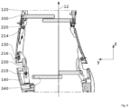
- FIG. 1 represents a schematic and general view of a robotic mannequin 10 according to an embodiment of the present invention.
- This robotic mannequin 10 comprises at least one frame 11 preferably extending along the longitudinal axis 12 of the robotic mannequin 10 and preferably configured to carry at least in part, preferably in full, a plurality of shells.
- the longitudinal axis 12 of the robotic mannequin 10 is parallel to the z axis
- the transverse axis 13 of the robotic mannequin 10 is parallel to the x axis
- the anteroposterior axis 14 of the robotic mannequin 10 is parallel to the y axis.
- the mannequin comprises six sets of shells, these sets being juxtaposed in x following the z direction, with for this example, three front sets and three rear sets, respectively representing a stop zone and a back zone of the mannequin.
- the Figure 1 shows sets of four shells articulated in series along the z-axis. Two shoulder shells complete these sets and provide height adjustment.
- FIG. 2 represents a sectional view along the YZ plane of a robotic mannequin 10 according to an embodiment of the present invention.
- This figure schematically represents the interior of the robotic mannequin 10.
- a plurality of shells 110, 120, 130, 140, 150, 160, 170, 180
- a plurality of actuators 310, 320, 330, 340, 350, 360, 370, 380, 390, 395 configured to move said plurality of shells (110, 120, 130, 140, 150, 160, 170, 180).
- the seventh actuator 370 is configured to move the sixth shell 160.
- the robotic mannequin 10 has the capacity to have its morphology modified both on its front part, but also on its rear part.
- the entire morphology of the robotic mannequin is modifiable.
- a plurality of kinematic links (210, 220, 230) kinematically coupling together a portion of the plurality of shells.
- FIG. 3 represents an enlargement of a part of the Figure 2 .
- the first shell 110 is kinematically coupled to the second shell 120 through the first kinematic link 210.
- this first kinematic link 210 comprises a sliding pivot link 215 configured to move in a slide 216.
- the second actuator 320 drives (preferably pushes forward or pulls backward along the anteroposterior axis 14 of the robotic mannequin 10) the first shell 110, this first kinematic link 210 is configured so that the second shell 120 is also driven in movement.
- this first kinematic link 210 comprises at least two degrees of freedom.
- this first kinematic link 210 comprises a first degree of freedom along the first axis of rotation 212 of the sliding pivot link 215.
- This axis of rotation 212 is preferably parallel to the transverse axis 14 of the robotic mannequin 10, i.e. parallel to the x axis.
- the actuators (310, 320, 330, 340, 350, 360, 370, 380, 390, 395) each apply at least one translational movement along a translational axis carried by a plane transverse to the longitudinal axis 12, that is to say by a plane parallel to the X-Y plane.
- this first kinematic connection 210 comprises a second degree of freedom along an axis parallel to the longitudinal axis 12, i.e. parallel to the Z axis.
- This degree of freedom corresponds to the sliding of the sliding pivot 215 in the slide 216.
- the sliding of the sliding pivot 215 in the slide 216 comprises a non-zero component along an axis parallel to the longitudinal axis 12.
- the sliding of the sliding pivot 215 can be done along another translation axis.
- first shell 110 when the first shell 110 is moved, part of its movement is transmitted to the second shell 120 by means of the first kinematic link 210 and vice versa.
- This kinematic coupling allows the first shell 110 and the second shell 120 to present a surface, i.e. a topographic profile, which can be moved in the three directions of space.
- the first kinematic connection 210 comprises a first part mechanically secured to the first shell 110 and preferably to the second actuator 320, and a second part mechanically secured to the second shell 120.
- the third actuator 330 configured to drive (preferably to push forward or to pull backward along the anteroposterior axis 14 of the robotic mannequin 10) the second shell 120.
- the second shell 120 is preferably kinematically coupled via the first kinematic link 210 with the first shell 110 so that the movement of the first shell 110 drives the second shell 120.
- the kinematic coupling by the first kinematic link 210 transmits to the second shell 120 in part at least certain components of the displacement of the first shell 110 convolved with the degrees of freedom of the first kinematic link 210.
- the third actuator 330 is mechanically secured to the second shell 120 via a pivot connection 214.
- the thrust transmission area between the actuator 330 and the shell 120 is located near the connection 220 to have a significant effect on the size of the dummy. It can be located in the lower quarter or even eighth of the height of the shell 120.
- FIG. 4 represents an enlargement of a part of the Figure 2 .
- the second shell 120 kinematically coupled with the third shell 130 through the second kinematic link 220 comprising the pivot link 214.
- This pivot link 214 has, according to one embodiment, only a single degree of freedom in rotation around an axis parallel to the transverse axis 13 of the robotic mannequin, that is to say around an axis parallel to the x axis.
- the third shell 130 is kinematically coupled with the fourth shell 140 through the third kinematic link 230.
- the third kinematic link 230 preferably comprises a sliding pivot link 215 configured to move in a slide 216.
- the third kinematic link 230 has the same technical characteristics and degrees of freedom as the first kinematic link 210.
- the first 210 and the third 230 kinematic links comprise a number of degrees of freedom greater than the number of degrees of freedom comprised in the second kinematic link 220.
- first 110, the second 120 and the third 130 shells form a continuous kinematic chain comprising at least three kinematic links (210, 220, 230), at least two of which comprise a sliding pivot link 215 and at least one comprising a simple pivot link 214.
- This continuous kinematic chain is then mobile relative to the frame 11 of the robotic mannequin 10 via the use of at least one actuator, preferably at least two actuators, and advantageously at least three actuators.
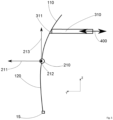
- FIG. 5 represents the kinematic coupling between two shells.
- the first shell 110 is kinematically coupled to the second shell 120 through the first kinematic link 210.
- the first kinematic link 210 comprises at least two degrees of freedom, one in translation along the first translation axis 213 and one in rotation along the first rotation axis 212.
- the first kinematic connection 210 allows the first shell 110 and the second shell 120 to be movable in translation according to a displacement comprising a component along the first translation axis 211 and a component along the second translation axis 213.
- the first translation axis 211 is parallel to the y axis and therefore to the anteroposterior axis 14 of the robotic mannequin 10
- the second translation axis 213 is parallel to the z axis and therefore to the longitudinal axis 12 of the robotic mannequin 10.
- This figure also shows the movement 400 of the first actuator 310.
- the first actuator 310 is configured to produce a movement along the first translation axis 211.
- the first actuator 310 comprises an arm movable in translation along the first translation axis 211 so as to push or pull the first shell 110 via a contact point 311 between the first actuator 310 and the first shell 110.
- This contact point 210 may or may not comprise a pivot.
- the second shell 120 comprises a part mechanically secured to the first kinematic connection 210 and a part mechanically secured to the frame 11 through a mechanical coupling zone 15 to the frame 11.
- This mechanical coupling zone 15 may comprise a pivot, for example, defining a limit to the movement of the second shell 120.
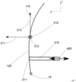
- FIG. 6 represents another embodiment of the present invention, compatible with the previous one, in which the first shell 110 is still kinematically coupled to the second shell 120 through the first kinematic link 210.
- the first actuator 310 is mechanically integral with the first kinematic link 210 which is, here again, movable according to two degrees of freedom, one in rotation around the first axis of rotation 212 and the other in translation according to the second axis of translation 213. It will be noted that the application by the first actuator 310 of a translational movement according to the first axis of translation 211 causes, by means of the two degrees of freedom of the first kinematic link 210, the movement of the latter according to a translation according to the first axis of translation 211.
- the first actuator 310 can pull or push the first kinematic link 210 thus driving the first 110 and the second 120 shells.
- the first actuator 310 may have mobility according to several degrees of freedom so as to allow the movement of the first connection.
- kinematics 210 according to several degrees of freedom in addition to the previous ones cited in relation to this figure.
- FIG. 7 represents another embodiment, similar to that of the Figure 5
- the first actuator 310 is found in mechanical contact at the contact point 311 with the second shell 120.
- This second shell 120 is on the one hand mechanically coupled to the armature 11 at the mechanical coupling zone 15 and on the other hand kinematically coupled to the first shell 110 at the first kinematic connection 210.
- the movement of the first actuator 310 along the y axis causes the movement of the first shell 110 according to a movement having a component along the y axis, as well as the movement of the first kinematic link 310 and of the first shell 110, both according to movements having components along the y axis.
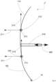
- FIG. 8 depicts an embodiment of the present invention showing the first kinematic link 210 kinematically coupling the first shell 110 with the second shell 120 and the second kinematic link 220 kinematically coupling the second shell 120 with the third shell 130.
- the third shell 130 comprises a zone, preferably an end, of mechanical coupling 15 with the frame 11 of the robotic mannequin 10.
- the first actuator 310 is arranged at the level of the second shell 120.
- this causes the movement of the second shell 120 and by kinematic coupling with the first shell 110 and the third shell 130, the movement of the first 110 and the third 130 shells, this coupling being achieved by the first 210 and the second 220 kinematic links.
- the first actuator 310 is in contact with the first kinematic link 210
- the second actuator 320 is in contact with the second kinematic link 220.
- the movement along the y axis of the first 310 and second 320 actuators causes the movement of the first 110, second 120 and third 130 shells relative to the frame 11.
- FIG. 10 represents an embodiment substantially similar to the previous one where the first 310 and second 320 actuators are arranged respectively in mechanical contact with the first 110 and the third 130 shells by means of contact points 311 and 321 respectively.
- the second kinematic link 220 comprises a pivot link 214 and has a single degree of freedom.
- This single degree of freedom corresponds to a rotation around the first axis of rotation 212 parallel to the transverse axis 13 of the robotic mannequin 10.
- one or a plurality of kinematic links may be of an elastic nature and thus comprise at least one or more return elements.
- an elastic link such as an elastomer ring, may provide such a connection.
- the actuators may be mechanical, hydraulic, electrical and/or pneumatic. Preferably, their design is simplified by giving them only a translation function along a single axis, preferably in a plane perpendicular to the axis 12.
- the actuators are either in point support on the shells, or assembled with them, for example by a ball joint.
- the present invention is not limited to a specific embodiment described in these figures.
- the present invention relates to any arrangement of shells kinematically coupled to each other by at least one kinematic connection.
- the shells kinematically coupled to each other form sets of articulated shells.
- the robotic mannequin is covered with sets of articulated shells, certain sets of shells being able, for example, also to be kinematically coupled to each other.
- the kinematic links can be arranged between the hulls in a vertical or horizontal alignment.
- one or more shells may have a mechanical coupling zone with the frame, this zone may or may not have one or more degrees of freedom.
- the present invention makes it possible to simultaneously move several shells using a single actuator, for example, so that the movement of the shells remains harmonious with respect to the silhouette of the robotic mannequin.
- the kinematic coupling of the shells improves the topology harmony of the robotic mannequin body.
- This kinematic coupling allows for a humanization of the robotic mannequin's silhouette.
Landscapes
- Engineering & Computer Science (AREA)
- Textile Engineering (AREA)
- Manipulator (AREA)
Claims (15)
- Robotisches Mannequin (10), der eine Längsabmessung aufweist, die sich entlang einer Längsachse (12) erstreckt, die einer Höhenabmessung eines Individuums entspricht und mindestens ein Gestell (11) und eine Vielzahl von Schalen umfasst, die sich über mindestens einen Teil des Gestells (11) erstrecken und in Bezug auf das Gestell (11) beweglich sind, wobei das robotische Mannequin (10) geeignet ist, auf Anfrage mindestens die Morphologie eines Individuums durch mechanische Steuerung der Vielzahl von Schalen nachzubilden, wobei das robotische Mannequin (10) dadurch gekennzeichnet ist, dass:- die Vielzahl von Schalen mindestens einen Satz von Gelenkschalen aufweisen, der mindestens eine erste Schale (110) und eine zweite Schale (120) umfasst, wobei die erste Schale (110) und die zweite Schale (120) durch mindestens eine erste kinematische Verbindung (210) kinematisch miteinander gekoppelt sind;- die erste kinematische Verbindung (210) mindestens einen Freiheitsgrad entlang einer ersten Drehachse (212) aufweist;- Er mindestens einen ersten Stellantrieb (310) umfasst, der so eingerichtet ist, dass er eine Translationsbewegung, entlang einer ersten Translationsachse (211) orthogonal zur ersten Drehachse, auf mindestens eine der mindestens Folgenden ausübt: die erste Schale (110), die zweite Schale (120), die erste kinematische Verbindung (210); und mindestens einen zweiten Stellantrieb (320), der so eingerichtet ist, dass er eine Translationsbewegung entlang der ersten Translationsachse (211) auf mindestens eine der mindestens Folgenden ausübt: die erste Schale (110), die zweite Schale (120), die erste kinematische Verbindung (210).
- Robotisches Mannequin (10) nach dem vorhergehenden Anspruch, wobei die erste Translationsachse (211) von einer Ebene quer zur Längsachse (12) getragen wird, und wobei die erste Drehachse (212) von einer Ebene quer zur Längsachse (12) getragen wird.
- Robotisches Mannequin (10) nach einem der vorhergehenden Ansprüche, wobei die erste (110) und die zweite (120) Schale so eingerichtet sind, dass sie die Querabmessung der Außenfläche des robotischen Mannequins (10) in mindestens einer Ebene quer zur Längsachse (12) variieren.
- Robotisches Mannequin (10) nach einem der vorhergehenden Ansprüche, wobei der erste Stellantrieb (310) so eingerichtet ist, dass er die Translationsbewegung nur entlang der ersten Translationsachse (211) ausführt.
- Robotisches Mannequin (10) nach einem der vorhergehenden Ansprüche, wobei die erste kinematische Verbindung (210) eine Schwenkverbindung (214) zwischen der ersten (110) und der zweiten (120) Schale umfasst, wobei die Schwenkverbindung (214) um die erste Drehachse (212) drehbar ist.
- Robotisches Mannequin (10) nach einem der vorhergehenden Ansprüche, wobei die erste kinematische Verbindung (210) einen zweiten Freiheitsgrad gemäß einer zweiten Translationsachse (211, 213) orthogonal zur ersten Drehachse (212) aufweist.
- Robotisches Mannequin (10) nach dem vorhergehenden Anspruch, wobei die erste kinematische Verbindung eine gleitende Schwenkverbindung (215) zwischen der ersten (110) und der zweiten Schale (120) umfasst, wobei die gleitende Schwenkverbindung (215) um die erste Drehachse (212) und in der Translation entlang der zweiten Translationsachse (211, 213) beweglich ist.
- Robotisches Mannequin (10) nach einem der vorhergehenden Ansprüche, wobei die Vielzahl von Schalen teilweise mindestens eine durchgehende Kinematikkette definiert, die sich über mindestens einen Teil des Stamms des robotischen Mannequins (10) erstreckt.
- Robotisches Mannequin (10) nach einem der vorhergehenden Ansprüche, wobei mindestens eine der ersten Schale (110) und der zweiten Schale (120) über mindestens eine Drehverbindung (15) mit mindestens einem Grad an Freiheit bei der Drehung um die erste Drehachse (212) mechanisch mit dem Gestell (11) des robotischen Mannequins (10) gekoppelt ist.
- Robotisches Mannequin (10) nach einem der vorhergehenden Ansprüche, wobei die erste kinematische Verbindung (210) eine elastische Verbindung ist, die ein erstes Rückstellelement umfasst.
- Robotisches Mannequin (10) nach einem der vorhergehenden Ansprüche, wobei der Gelenkschalensatz mindestens eine dritte Schale (130) umfasst, die durch mindestens eine zweite kinematische Verbindung (220) mit mindestens einer der ersten (110) und zweiten (120) Schalen kinematisch gekoppelt ist.
- Robotisches Mannequin (10) nach einem der vorhergehenden Ansprüche, wobei der Gelenkschalensatz eine dritte (130) und eine vierte (140) Schale umfasst, wobei die dritte Schale (130) durch mindestens eine zweite kinematische Verbindung (220) mit der zweiten Schale (120) kinematisch gekoppelt ist und die vierte Schale (140) durch mindestens eine dritte kinematische Verbindung (230) mit der dritten Schale (130) kinematisch gekoppelt ist, wobei die erste (210) und die dritte (230) kinematische Verbindungen die gleiche Anzahl von Freiheitsgraden aufweisen, und vorzugsweise die gleichen Freiheitsgrade, und wobei die zweite kinematische Verbindung (220) eine geringere Anzahl von Freiheitsgraden aufweist als die Anzahl von Freiheitsgraden der ersten (210) und der dritten (230) kinematischen Verbindung und wobei die erste (210) und die dritte (230) kinematische Verbindung auf beiden Seiten der zweiten kinematischen Verbindung (220) angeordnet sind.
- Robotisches Mannequin (10) nach einem der vorhergehenden Ansprüche, der eine Vielzahl von nebeneinander liegenden Gelenkschalensätze umfasst.
- Robotisches Mannequin (10) nach dem vorhergehenden Anspruch, wobei mindestens zwei Gelenkschalensätze aus der Vielzahl der Gelenkschalensätzen kinematisch miteinander gekoppelt sind.
- System, das mindestens ein robotisches Mannequin (10) nach einem der vorhergehenden Ansprüche und mindestens eine Steuerelektronik des ersten Stellantriebs (310) des robotischen Mannequins (10) umfasst, wobei die Steuerelektronik Steuerbefehle von mindestens einem Computerprogrammprodukt empfängt, das Anweisungen umfasst, die, wenn sie von mindestens einem Prozessor ausgeführt werden, eine Reihe von Steuerbefehlen an diese Steuerelektronik senden.
Applications Claiming Priority (2)
| Application Number | Priority Date | Filing Date | Title |
|---|---|---|---|
| FR2104231A FR3122066B1 (fr) | 2021-04-23 | 2021-04-23 | Mannequin robotisé |
| PCT/EP2022/059420 WO2022223319A1 (fr) | 2021-04-23 | 2022-04-08 | Mannequin robotisé |
Publications (3)
| Publication Number | Publication Date |
|---|---|
| EP4340668A1 EP4340668A1 (de) | 2024-03-27 |
| EP4340668C0 EP4340668C0 (de) | 2025-05-28 |
| EP4340668B1 true EP4340668B1 (de) | 2025-05-28 |
Family
ID=76034860
Family Applications (1)
| Application Number | Title | Priority Date | Filing Date |
|---|---|---|---|
| EP22722152.0A Active EP4340668B1 (de) | 2021-04-23 | 2022-04-08 | Robotisches mannequin |
Country Status (5)
| Country | Link |
|---|---|
| US (1) | US12070094B2 (de) |
| EP (1) | EP4340668B1 (de) |
| ES (1) | ES3039520T3 (de) |
| FR (1) | FR3122066B1 (de) |
| WO (1) | WO2022223319A1 (de) |
Families Citing this family (1)
| Publication number | Priority date | Publication date | Assignee | Title |
|---|---|---|---|---|
| CN115399535A (zh) * | 2021-05-28 | 2022-11-29 | 美国适着三维科技有限公司 | 人体模型 |
Family Cites Families (14)
| Publication number | Priority date | Publication date | Assignee | Title |
|---|---|---|---|---|
| US1102596A (en) * | 1912-11-25 | 1914-07-07 | Isaac Levin | Adjustable garment-form. |
| US1717477A (en) * | 1926-10-30 | 1929-06-18 | Charles A Ufford | Dress form |
| US2005399A (en) * | 1929-08-05 | 1935-06-18 | Sterling Ernst | Apparatus for the tailoring trade for reproducing the shape of the body of the customer |
| US2646907A (en) * | 1952-03-14 | 1953-07-28 | Clawsey Eva | Dress form |
| US3191821A (en) * | 1963-05-29 | 1965-06-29 | Ellanam Adjustable Dress Form | Dress form |
| US3734362A (en) * | 1970-08-26 | 1973-05-22 | E Arthur | Dressmaking forms |
| US4493445A (en) * | 1982-06-01 | 1985-01-15 | A. E. Arthur Limited | Bodyforms |
| US5265779A (en) * | 1992-12-15 | 1993-11-30 | Jiang Jong Ming | Mannequin with adjustable parts |
| US6196429B1 (en) * | 1999-04-28 | 2001-03-06 | Cyberform Corp. | Dress or clothing form |
| US20070275632A1 (en) * | 2006-05-26 | 2007-11-29 | Massimo Barra | Adjustable dress form system |
| US8186546B2 (en) * | 2009-11-23 | 2012-05-29 | Wang Xiaoman | Adjustable dress form |
| CN103564899A (zh) * | 2012-08-07 | 2014-02-12 | 香港理工大学 | 智能可调节型人体模型 |
| CN105919202A (zh) * | 2016-06-27 | 2016-09-07 | 深圳市尚魅信息科技有限公司 | 数控服装人台 |
| WO2020010441A1 (en) * | 2018-07-09 | 2020-01-16 | Kevin Nielson | Shape-adjustable chroma key compatible mannequin or body suit, and associated 3d image capture equipment |
-
2021
- 2021-04-23 FR FR2104231A patent/FR3122066B1/fr active Active
- 2021-12-02 US US17/540,897 patent/US12070094B2/en active Active
-
2022
- 2022-04-08 WO PCT/EP2022/059420 patent/WO2022223319A1/fr not_active Ceased
- 2022-04-08 EP EP22722152.0A patent/EP4340668B1/de active Active
- 2022-04-08 ES ES22722152T patent/ES3039520T3/es active Active
Also Published As
| Publication number | Publication date |
|---|---|
| EP4340668C0 (de) | 2025-05-28 |
| FR3122066B1 (fr) | 2023-05-19 |
| WO2022223319A1 (fr) | 2022-10-27 |
| US20220338587A1 (en) | 2022-10-27 |
| US12070094B2 (en) | 2024-08-27 |
| FR3122066A1 (fr) | 2022-10-28 |
| ES3039520T3 (en) | 2025-10-22 |
| EP4340668A1 (de) | 2024-03-27 |
Similar Documents
| Publication | Publication Date | Title |
|---|---|---|
| TW201223819A (en) | Bicycle derailleur and method | |
| WO2009144320A1 (fr) | Robot humanoide mettant en oeuvre une articulation spherique a actionneurs couples | |
| WO2001081791A1 (fr) | Actionneur conçu pour des structures articulées, telles que des membres de robot marcheur | |
| FR2832345A1 (fr) | Mecanisme articule comprenant un reducteur a cable utilisable dans un bras de robot | |
| EP4340668B1 (de) | Robotisches mannequin | |
| EP2321170B1 (de) | Fuss für einen humanoidroboter | |
| FR2850599A1 (fr) | Dispositif de deplacement et d'orientation d'un objet dans l'espace et utilisation en usinage rapide | |
| FR2912622A1 (fr) | Dispositif de reglage de fauteuil inclinable. | |
| CA2411915A1 (fr) | Bras de commande a deux branches en parallele | |
| FR3070669A1 (fr) | Deploiement d'un element aerodynamique de carrosserie | |
| EP3245052B1 (de) | Trommel zum herstellen eines reifenrohlings | |
| FR2661665A1 (fr) | Fleche de manutention comprenant une fleche principale et une fleche complementaire. | |
| EP0491613B1 (de) | Handhabungsgerät zum Bewegen eines Gegenstandes in Raum, z.B. parallel mit sichselbst | |
| FR2647046A1 (fr) | Robot industriel fixe indifferemment au sol ou au plafond | |
| FR2940745A1 (fr) | Ensemble a vehicule tracteur et machine de traitement du sol, telle qu'une machine de debroussaillage-broyage de vegetaux | |
| CA2863493A1 (fr) | Bati de montage de portiere de vehicule | |
| LU85922A1 (fr) | Installation de soudage a mouvement orbital | |
| EP1529722A2 (de) | Spurstellvorrichtung für Räder einer selben Achse | |
| EP0612542B1 (de) | In drei Richtungen periodische Bewegungen reproduzierende Plattform, mit einer bevorzugten Richtung | |
| EP0733583A1 (de) | Selbstaufstellender Kran mit seitlich klappbarem Ausleger | |
| EP2504158B1 (de) | Vulkanisierungspresse für einen reifenrohling mit schwenkbarem deckel | |
| EP4401926B1 (de) | Neue architektur für ein mobiles robotersystem | |
| FR2730643A1 (fr) | Module d'escalade permettant la constitution d'un mur d'escalade a geometrie variable | |
| EP0148054A1 (de) | Gelenkkopf für Roboter und Roboter ausgestattet mit einem derartigen Gelenkkopf | |
| WO2023041871A1 (fr) | Ensemble d'articulation d'une tête mobile de robot |
Legal Events
| Date | Code | Title | Description |
|---|---|---|---|
| STAA | Information on the status of an ep patent application or granted ep patent |
Free format text: STATUS: UNKNOWN |
|
| STAA | Information on the status of an ep patent application or granted ep patent |
Free format text: STATUS: THE INTERNATIONAL PUBLICATION HAS BEEN MADE |
|
| PUAI | Public reference made under article 153(3) epc to a published international application that has entered the european phase |
Free format text: ORIGINAL CODE: 0009012 |
|
| STAA | Information on the status of an ep patent application or granted ep patent |
Free format text: STATUS: REQUEST FOR EXAMINATION WAS MADE |
|
| 17P | Request for examination filed |
Effective date: 20240209 |
|
| AK | Designated contracting states |
Kind code of ref document: A1 Designated state(s): AL AT BE BG CH CY CZ DE DK EE ES FI FR GB GR HR HU IE IS IT LI LT LU LV MC MK MT NL NO PL PT RO RS SE SI SK SM TR |
|
| DAV | Request for validation of the european patent (deleted) | ||
| DAX | Request for extension of the european patent (deleted) | ||
| GRAP | Despatch of communication of intention to grant a patent |
Free format text: ORIGINAL CODE: EPIDOSNIGR1 |
|
| STAA | Information on the status of an ep patent application or granted ep patent |
Free format text: STATUS: GRANT OF PATENT IS INTENDED |
|
| INTG | Intention to grant announced |
Effective date: 20241219 |
|
| GRAS | Grant fee paid |
Free format text: ORIGINAL CODE: EPIDOSNIGR3 |
|
| GRAA | (expected) grant |
Free format text: ORIGINAL CODE: 0009210 |
|
| STAA | Information on the status of an ep patent application or granted ep patent |
Free format text: STATUS: THE PATENT HAS BEEN GRANTED |
|
| AK | Designated contracting states |
Kind code of ref document: B1 Designated state(s): AL AT BE BG CH CY CZ DE DK EE ES FI FR GB GR HR HU IE IS IT LI LT LU LV MC MK MT NL NO PL PT RO RS SE SI SK SM TR |
|
| REG | Reference to a national code |
Ref country code: GB Ref legal event code: FG4D Free format text: NOT ENGLISH |
|
| REG | Reference to a national code |
Ref country code: CH Ref legal event code: EP |
|
| REG | Reference to a national code |
Ref country code: IE Ref legal event code: FG4D Free format text: LANGUAGE OF EP DOCUMENT: FRENCH Ref country code: DE Ref legal event code: R096 Ref document number: 602022015214 Country of ref document: DE |
|
| U01 | Request for unitary effect filed |
Effective date: 20250626 |
|
| U07 | Unitary effect registered |
Designated state(s): AT BE BG DE DK EE FI FR IT LT LU LV MT NL PT RO SE SI Effective date: 20250702 |
|
| PG25 | Lapsed in a contracting state [announced via postgrant information from national office to epo] |
Ref country code: NO Free format text: LAPSE BECAUSE OF FAILURE TO SUBMIT A TRANSLATION OF THE DESCRIPTION OR TO PAY THE FEE WITHIN THE PRESCRIBED TIME-LIMIT Effective date: 20250828 |
|
| PG25 | Lapsed in a contracting state [announced via postgrant information from national office to epo] |
Ref country code: PL Free format text: LAPSE BECAUSE OF FAILURE TO SUBMIT A TRANSLATION OF THE DESCRIPTION OR TO PAY THE FEE WITHIN THE PRESCRIBED TIME-LIMIT Effective date: 20250528 |
|
| PG25 | Lapsed in a contracting state [announced via postgrant information from national office to epo] |
Ref country code: HR Free format text: LAPSE BECAUSE OF FAILURE TO SUBMIT A TRANSLATION OF THE DESCRIPTION OR TO PAY THE FEE WITHIN THE PRESCRIBED TIME-LIMIT Effective date: 20250528 |
|
| PG25 | Lapsed in a contracting state [announced via postgrant information from national office to epo] |
Ref country code: RS Free format text: LAPSE BECAUSE OF FAILURE TO SUBMIT A TRANSLATION OF THE DESCRIPTION OR TO PAY THE FEE WITHIN THE PRESCRIBED TIME-LIMIT Effective date: 20250828 |
|
| PG25 | Lapsed in a contracting state [announced via postgrant information from national office to epo] |
Ref country code: IS Free format text: LAPSE BECAUSE OF FAILURE TO SUBMIT A TRANSLATION OF THE DESCRIPTION OR TO PAY THE FEE WITHIN THE PRESCRIBED TIME-LIMIT Effective date: 20250928 |
|
| REG | Reference to a national code |
Ref country code: GR Ref legal event code: EP Ref document number: 20250401687 Country of ref document: GR Effective date: 20251009 |
|
| PG25 | Lapsed in a contracting state [announced via postgrant information from national office to epo] |
Ref country code: SM Free format text: LAPSE BECAUSE OF FAILURE TO SUBMIT A TRANSLATION OF THE DESCRIPTION OR TO PAY THE FEE WITHIN THE PRESCRIBED TIME-LIMIT Effective date: 20250528 |
|
| PG25 | Lapsed in a contracting state [announced via postgrant information from national office to epo] |
Ref country code: CZ Free format text: LAPSE BECAUSE OF FAILURE TO SUBMIT A TRANSLATION OF THE DESCRIPTION OR TO PAY THE FEE WITHIN THE PRESCRIBED TIME-LIMIT Effective date: 20250528 |
|
| PG25 | Lapsed in a contracting state [announced via postgrant information from national office to epo] |
Ref country code: SK Free format text: LAPSE BECAUSE OF FAILURE TO SUBMIT A TRANSLATION OF THE DESCRIPTION OR TO PAY THE FEE WITHIN THE PRESCRIBED TIME-LIMIT Effective date: 20250528 |
|
| PLBE | No opposition filed within time limit |
Free format text: ORIGINAL CODE: 0009261 |
|
| STAA | Information on the status of an ep patent application or granted ep patent |
Free format text: STATUS: NO OPPOSITION FILED WITHIN TIME LIMIT |
|
| REG | Reference to a national code |
Ref country code: CH Ref legal event code: L10 Free format text: ST27 STATUS EVENT CODE: U-0-0-L10-L00 (AS PROVIDED BY THE NATIONAL OFFICE) Effective date: 20260409 |