EP4340010B1 - Chipgehäusestruktur und verpackungsverfahren und elektronische vorrichtung - Google Patents
Chipgehäusestruktur und verpackungsverfahren und elektronische vorrichtung Download PDFInfo
- Publication number
- EP4340010B1 EP4340010B1 EP21949634.6A EP21949634A EP4340010B1 EP 4340010 B1 EP4340010 B1 EP 4340010B1 EP 21949634 A EP21949634 A EP 21949634A EP 4340010 B1 EP4340010 B1 EP 4340010B1
- Authority
- EP
- European Patent Office
- Prior art keywords
- chip
- substrate
- molding part
- away
- supporting part
- Prior art date
- Legal status (The legal status is an assumption and is not a legal conclusion. Google has not performed a legal analysis and makes no representation as to the accuracy of the status listed.)
- Active
Links
Images


Classifications
-
- H—ELECTRICITY
- H10—SEMICONDUCTOR DEVICES; ELECTRIC SOLID-STATE DEVICES NOT OTHERWISE PROVIDED FOR
- H10W—GENERIC PACKAGES, INTERCONNECTIONS, CONNECTORS OR OTHER CONSTRUCTIONAL DETAILS OF DEVICES COVERED BY CLASS H10
- H10W74/00—Encapsulations, e.g. protective coatings
- H10W74/10—Encapsulations, e.g. protective coatings characterised by their shape or disposition
- H10W74/111—Encapsulations, e.g. protective coatings characterised by their shape or disposition the semiconductor body being completely enclosed
- H10W74/114—Encapsulations, e.g. protective coatings characterised by their shape or disposition the semiconductor body being completely enclosed by a substrate and the encapsulations
- H10W74/117—Encapsulations, e.g. protective coatings characterised by their shape or disposition the semiconductor body being completely enclosed by a substrate and the encapsulations the substrate having spherical bumps for external connection
-
- H—ELECTRICITY
- H10—SEMICONDUCTOR DEVICES; ELECTRIC SOLID-STATE DEVICES NOT OTHERWISE PROVIDED FOR
- H10W—GENERIC PACKAGES, INTERCONNECTIONS, CONNECTORS OR OTHER CONSTRUCTIONAL DETAILS OF DEVICES COVERED BY CLASS H10
- H10W40/00—Arrangements for thermal protection or thermal control
- H10W40/40—Arrangements for thermal protection or thermal control involving heat exchange by flowing fluids
- H10W40/47—Arrangements for thermal protection or thermal control involving heat exchange by flowing fluids by flowing liquids, e.g. forced water cooling
-
- H—ELECTRICITY
- H10—SEMICONDUCTOR DEVICES; ELECTRIC SOLID-STATE DEVICES NOT OTHERWISE PROVIDED FOR
- H10W—GENERIC PACKAGES, INTERCONNECTIONS, CONNECTORS OR OTHER CONSTRUCTIONAL DETAILS OF DEVICES COVERED BY CLASS H10
- H10W40/00—Arrangements for thermal protection or thermal control
- H10W40/60—Securing means for detachable heating or cooling arrangements, e.g. clamps
- H10W40/611—Bolts or screws
-
- H—ELECTRICITY
- H10—SEMICONDUCTOR DEVICES; ELECTRIC SOLID-STATE DEVICES NOT OTHERWISE PROVIDED FOR
- H10W—GENERIC PACKAGES, INTERCONNECTIONS, CONNECTORS OR OTHER CONSTRUCTIONAL DETAILS OF DEVICES COVERED BY CLASS H10
- H10W74/00—Encapsulations, e.g. protective coatings
- H10W74/10—Encapsulations, e.g. protective coatings characterised by their shape or disposition
- H10W74/111—Encapsulations, e.g. protective coatings characterised by their shape or disposition the semiconductor body being completely enclosed
- H10W74/121—Encapsulations, e.g. protective coatings characterised by their shape or disposition the semiconductor body being completely enclosed by multiple encapsulations, e.g. by a thin protective coating and a thick encapsulation
-
- H—ELECTRICITY
- H10—SEMICONDUCTOR DEVICES; ELECTRIC SOLID-STATE DEVICES NOT OTHERWISE PROVIDED FOR
- H10W—GENERIC PACKAGES, INTERCONNECTIONS, CONNECTORS OR OTHER CONSTRUCTIONAL DETAILS OF DEVICES COVERED BY CLASS H10
- H10W42/00—Arrangements for protection of devices
- H10W42/121—Arrangements for protection of devices protecting against mechanical damage
Definitions
- This application relates to the field of microelectronic technologies, and in particular, to a chip package structure, a packaging method, and an electronic device.
- a chip with high power consumption for example, a chip in a flip chip ball grid array (FCBGA) packaging form, generates much heat in a working process. Most of the heat is conducted to a back side of the chip, and the heat is dissipated from the back side of the chip.
- FCBGA flip chip ball grid array
- a liquid cooling manner may be used for heat dissipation.
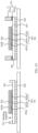
- a refrigerating apparatus 101 is fastened to a printed circuit board (printed circuit board, PCB) 103 by using a spring screw 102, and an accommodation cavity 107 is formed between a chip 106 and the refrigerating apparatus 101 by using a supporting part 104 and a sealing kit 105.
- a cooling medium enters the accommodation cavity 107 from a liquid inlet 101a and a sprinkler-shaped flow channel 101b to perform heat exchange with the chip, and flows out of the accommodation cavity 107 from a liquid return port 101c.
- the chip 106 needs to be in direct contact with the cooling medium.
- the cooling medium exists on an upper surface of the chip 106 and in the accommodation cavity 107 on a side surface of the chip 106.
- the adhesive layer is prone to failure.
- an underfill adhesive between the chip 106 and the substrate 108 has a risk of cooling medium penetration.
- the cooling medium may penetrate into the chip 106 from the back of the chip 106.
- Document US 2021/159139 A1 describes a semiconductor device including a substrate, a semiconductor package, a plurality of pillars and a lid is provided.
- Document US 2021/098335 A1 describes a package structure including a wafer-form semiconductor package and a thermal dissipating system.
- Document WO 2021/119930 A1 describes a chip package and a fabrication method therefor used to mitigate the deformation of a heat dissipation sheet caused by the deformation of a substrate.
- Document CN 108933108 A describes semiconductor device package including a substrate, a semiconductor chip, a first ring structure and asecond ring structure, and a method of manufacturing the same.
- Document US 2009/316360 A1 describes a cooling apparatus and method of fabrication for facilitating removal of heat from a heat-generating electronic device.
- Document US 2010/148358 A1 describes a semiconductor device having a higher thermal dissipation efficiency includes a thermally conducting structure attached to a surface of the semiconductor device via soldering.
- Embodiments of this application provide a chip package structure, a packaging method, and an electronic device, to resolve a problem of low waterproof performance of a chip.
- a chip package structure includes: a substrate; a chip, having a first surface close to the substrate and a second surface opposite to the first surface; a first pin layer, including a plurality of first pins disposed between the first surface of the chip and the substrate; a molding part, disposed on a periphery of the chip and the first pin layer, where a surface that is of the molding part and that is away from the substrate is higher than the first surface of the chip, and covers a side surface of the first pin layer and at least a part of a side surface of the chip, and the molding part is attached to the side surface of the chip; and a waterproof layer, disposed on the second surface of the chip and the surface that is of the molding part and that is away from the substrate.
- the molding part is disposed on the periphery of the chip and the first pin layer
- the waterproof layer is disposed on the surface that is of the molding part and that is away from the substrate and the second surface of the chip, so that the molding part can prevent a refrigerating medium from penetrating into the first pin layer or the chip from the side surface of the first pin layer and the side surface of the chip
- the waterproof layer can prevent the refrigerating medium from penetrating into the chip from a surface of the chip and prevent the refrigerating medium from penetrating into the chip from the molding part, to improve waterproof performance of the chip, and improve reliability of the chip.
- the molding part is disposed on the substrate. Because the molding part has a large modulus and cannot be easily deformed, deformation of the substrate may be limited when the substrate warps, to reduce a warping degree of the substrate. This reduces circuit faults caused by deterioration in the waterproof performance and poor contact.
- the molding part covers all side surfaces of the chip, and the surface that is of the molding part and that is away from the substrate may be flush with the second surface of the chip.
- a distance between the surface that is of the molding part and that is away from the substrate and the substrate is equal to a distance between the second surface of the chip and the substrate.
- the molding part covers all the side surfaces of the chip, and when an edge of the chip is squeezed by an external force, the molding part can implement a buffering function, to better protect the chip and further improve the reliability.
- the surface that is of the molding part and that is away from the substrate is flush with the second surface of the chip, so that the waterproof layer can be easily processed.
- the surface that is of the molding part and that is away from the substrate may be lower than the second surface of the chip.
- the distance between the surface that is of the molding part and that is away from the substrate and the substrate is less than the distance between the second surface of the chip and the substrate.
- the chip package structure may further include: a supporting part, disposed on the substrate.
- the supporting part surrounds the molding part, and an outer side surface of the molding part is attached to an inner side surface of the supporting part.
- pressure may be applied to an edge of the substrate by using the supporting part, to reduce the warping degree of the substrate. This reduces the circuit faults caused by the deterioration in the waterproof performance and the poor contact.
- the refrigerating medium can be prevented from penetrating into the chip from the outer side surface of the molding part, to further improve waterproof effect.
- a surface that is of the supporting part and that is away from the substrate is higher than the second surface of the chip.
- a distance between the surface that is of the supporting part and that is away from the substrate and the substrate may be greater than the distance between the second surface of the chip and the substrate.
- a surface that is of the supporting part and that is away from the substrate may be lower than the second surface of the chip.
- a distance between the surface that is of the supporting part and that is away from the substrate and the substrate may be less than the distance between the second surface of the chip and the substrate.
- the chip package structure may further include: a refrigerating apparatus, including a liquid inlet, a liquid return port, and a sprinkler-shaped flow channel.
- a refrigerating apparatus including a liquid inlet, a liquid return port, and a sprinkler-shaped flow channel.
- An accommodation cavity for accommodating a refrigerant is formed between the sprinkler-shaped flow channel, the liquid return port, and the waterproof layer, and the accommodation cavity covers at least the waterproof layer corresponding to the second surface of the chip.
- the liquid inlet is in communication with the sprinkler-shaped flow channel
- the sprinkler-shaped flow channel is in communication with the accommodation cavity
- the accommodation cavity is in communication with the liquid return port.
- the accommodation cavity formed between the refrigerating apparatus and the chip may completely cover areas that are on the waterproof layer and that correspond to the second surface of the chip.
- heat dissipation can be implemented on the second surface of the chip, and pins may be arranged in all the areas corresponding to the second surface, without a limitation.
- a sealing force is applied outside the second surface of the chip to reduce a risk that the chip is damaged by an external force. This ensures the waterproof performance, heat dissipation efficiency, and the reliability.
- an electronic device includes a printed circuit board and at least one chip package structure according to any design solution of the first aspect, and the chip package structure is connected to the printed circuit board.
- the electronic device provided in the second aspect has a same technical effect as the chip package structure provided in the first aspect. Details are not described herein again.
- the electronic device may include an electronic product such as a server or a super computer. It may be understood that the electronic device may further include an electronic product used for industrial control, an electronic product of a data center, or the like.
- a chip packaging method includes: forming, on a substrate, a molding part that surrounds a chip, where the chip is disposed on the substrate, the chip has a first surface close to the substrate and a second surface opposite to the first surface, the first surface is connected to the substrate through a first pin layer, the first pin layer includes a plurality of first pins disposed between the first surface of the chip and the substrate, a surface that is of the molding part and that is away from the substrate is higher than the first surface of the chip, the molding part covers a side surface of the first pin layer and at least a part of a side surface of the chip, and the molding part is attached to the side surface of the chip; and forming a waterproof layer on the second surface of the chip and the surface that is of the molding part and that is away from the substrate.
- the molding part covers all side surfaces of the chip, and the surface that is of the molding part and that is away from the substrate may be flush with the second surface of the chip.
- the surface that is of the molding part and that is away from the substrate may be lower than the second surface of the chip.
- the chip packaging method may further include: forming, on a periphery of the chip, an enclosure dam for limiting the molding part.
- the enclosure dam is located on the substrate.
- the forming, on a substrate, a molding part that surrounds a chip may include: forming the molding part between the enclosure dam and the chip.
- the enclosure dam may be a supporting part, and an outer side surface of the molding part is attached to an inner side surface of the supporting part.
- a surface that is of the supporting part and that is away from the substrate is higher than the second surface of the chip.
- the surface that is of the supporting part and that is away from the substrate may be lower than the second surface of the chip.
- the chip packaging method may further include: connecting the substrate to a printed circuit board.
- the chip packaging method may further include: connecting the substrate to a printed circuit board.
- the chip packaging method in the third aspect and the chip packaging structure provided in the first aspect have a same technical effect. Details are not described herein again.
- orientation terms such as “top” and “bottom” are defined relative to orientations of structures in the accompanying drawings. It should be understood that these position terms are relative concepts used for relative description and clarification, and may correspondingly change based on changes in the orientations of the structures.
- connection should be understood in a broad sense unless otherwise expressly specified and limited.
- connection may be a fixed connection, or may be a detachable connection or an integrated connection; and may be a direct connection, or may be an indirect connection through an intermediate medium.
- a term “coupling” may be a manner of implementing an electrical connection for signal transmission. The “coupling” may be a direct electrical connection, or may be an indirect electrical connection through an intermediate medium.
- the electronic device includes an electronic device such as a server or a super computer. It may be understood that the electronic device may further include an electronic device used for industrial control, an electronic device of a data center, or the like. A specific form of the foregoing electronic device is not specifically limited in this embodiment of this application.
- the electronic device may include a printed circuit board (printed circuit board, PCB) 300 shown in FIG. 4 and a chip package structure 400 disposed on the printed circuit board 300.
- the chip package structure 400 is connected to the printed circuit board 300 by using a plurality of pins.
- the following describes in detail the chip package structure 400 and a chip packaging method with reference to FIG. 5 to FIG. 24 .
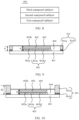
- the chip package structure 400 includes a substrate 401, a chip (Die) 402, a first pin layer 403, a molding part 404, and a waterproof layer 405.
- a placement orientation of the structure shown in FIG. 5 is used as an example.
- the first pin layer 403 is disposed on the substrate 401, and the chip 402 is disposed on the first pin layer 403.
- the following describes a location relationship between components in the chip package structure 400 with reference to this orientation.
- the chip 402 has a first surface 402a close to the substrate 401 and a second surface 402b opposite to the first surface 402a.
- a lower surface of the chip 402 is close to the substrate 401.
- the lower surface of the chip 402 is the first surface 402a.
- An upper surface of the chip 402 is away from the substrate 401.
- the upper surface of the chip 402 is the second surface 402b. It may be understood that an area of the first surface 402a or the second surface 402b may be larger than an area of any side surface of the chip 402.
- the first pin layer 403 includes a plurality of first pins 403a disposed between the first surface 402a of the chip 402 and the substrate 401.
- the first pin layer 403 is disposed between the lower surface of the chip 402 and the substrate 401, and the first pin layer 403 may include the plurality of first pins 403a.
- the plurality of first pins 403a in the foregoing first pin layer 403 may be solder bumps (solder bumps), solder balls (solder balls), or copper pillars (Cu pillars).
- the plurality of first pins 403a in the first pin layer 403 are arranged in an array.
- the plurality of first pins 403a form a solder ball grid array (ball grid array, BGA).
- the chip 402 and the substrate 401 may be electrically connected by using the plurality of first pins 403a.
- the first pin layer 403 may further include an underfill (Underfill) adhesive 403b.
- the underfill adhesive 403b is located in a gap between the first surface 402a and the substrate 401, to be specific, between the lower surface of the chip 402 and the substrate 401, and the underfill adhesive 403b may cover the plurality of first pins 403a.
- the underfill adhesive 403b refer to a specific implementation of the underfill adhesive 403b in a conventional technology. Details are not described herein.
- the molding (Molding) package 404 is disposed on a periphery of the chip 402 and the first pin layer 403.
- the molding part 404 is disposed around the chip 402 and the first pin layer 403.
- a surface that is of the molding part 404 and that is away from the substrate 401 is higher than the first surface 402a of the chip 402.
- an upper surface of the molding part 404 is higher than the lower surface of the chip 402.
- a distance between the surface that is of the molding part 404 and that is away from the substrate 401 and the substrate 401 is greater than a distance between the first surface 402a of the chip 402 and the substrate 401.
- a distance between the upper surface of the molding part 404 and the substrate 401 is greater than a distance between the lower surface of the chip 402 and the substrate 401.
- the molding part 404 covers a side surface of the first pin layer 403 and at least a part of a side surface of the chip 402.
- the molding part 404 shown in FIG. 5 and FIG. 6 covers all side surfaces of the first pin layer 403 and all side surfaces of the chip 402.
- the molding part 404 shown in FIG. 7 covers all the side surfaces of the first pin layer 403 and a part of a side surface of the chip 402, for example, a part of a side surface close to a side of the substrate 401.
- surfaces of the molding part 404 two surfaces other than a surface in contact with the substrate 401 and a surface opposite to the substrate 401 are side surfaces.
- two surfaces between the upper surface of the molding part 404 and the lower surface of the molding part 404 are two side surfaces of the molding part 404.
- a side surface with a smaller distance from the side surface of the chip 402 is an inner side surface of the molding part 404
- a side surface with a larger distance from the side surface of the chip 402 is an outer side surface of the molding part 404.
- the inner side surface of the molding part 404 is attached to a side surface that is of the chip 402 and that is covered by the molding part 404, and the inner side surface of the molding part 404 may be further attached to the side surface of the first pin layer 403.
- a surface that is of the molding part 404 and that is close to the substrate 401 may be attached to a surface that is of the substrate 401 and that is close to the chip 402.
- the lower surface of the molding part 404 may be attached to an upper surface of the substrate 401.
- a material of the molding part 404 may be made of one or both of the following thermosetting materials: epoxy plastic or phenolic plastic.
- the epoxy plastic may include an epoxy resin, a hardening agent, a filling agent, or an additive agent.
- the upper surface of the molding part 404 may be flush with the upper surface of the chip 402 in height, may be higher than the upper surface of the chip 402, or may be lower than the upper surface of the chip 402.
- the following uses examples for description with reference to FIG. 5 to FIG. 7 .
- the surface that is of the molding part 404 and that is away from the substrate 401 may be flush with the second surface 402b of the chip 402.
- the upper surface of the molding part 404 is flush with the upper surface of the chip 402.
- the distance between the surface that is of the molding part 404 and that is away from the substrate 401 and the substrate 401 may be equal to a distance between the second surface 402b of the chip 402 and the substrate 401.
- the distance between the upper surface of the molding part 404 and the substrate 401 may be equal to a distance between the upper surface of the chip 402 and the substrate 401.
- the molding part 404 may cover all the side surfaces of the chip 402.
- the distance between the surface that is of the molding part 404 and that is away from the substrate 401 and the substrate 401 is the thickness or the height of the molding part 404 on the substrate 401.
- the distance between the second surface 402b of the chip 402 and the substrate 401 is the thickness or the height of the chip 402 on the substrate 401.
- the molding part 404 covers all the side surfaces of the chip 402, so that refrigerating media that penetrate into the chip 402 from the side surface of the chip 402 may be further reduced, and waterproof performance may be further improved.
- the molding part 404 may implement a buffering function, to better protect the chip 402 and further improve reliability.
- the surface that is of the molding part 404 and that is away from the substrate 401 is flush with the second surface 402b of the chip 402, so that the waterproof layer 405 can be easily processed, to improve efficiency.
- the distance between the second surface 402b of the chip 402 and the substrate 401 is A
- the distance between the surface that is of the molding part 404 and that is away from the substrate 401 and the substrate 401 is also A.
- the molding part 404 may further implement a buffering function, to better protect the chip 402 and further improve reliability.
- B is greater than A.
- the surface that is of the molding part 404 and that is away from the substrate 401 may be lower than the second surface 402b of the chip 402.
- the upper surface of the molding part 404 is lower than the upper surface of the chip 402.
- the distance between the surface that is of the molding part 404 and that is away from the substrate 401 and the substrate 401 may be less than the distance between the second surface 402b of the chip 402 and the substrate 401.
- the distance between the upper surface of the molding part 404 and the substrate 401 may be less than the distance between the upper surface of the chip 402 and the substrate 401.
- the molding part 404 covers a part of the side surface of the chip 402. In this way, process flows may be reduced. For example, in a process of forming the molding part 404, raw materials of the molding part 404 flowing to the second surface 402b of the chip 402 may be reduced, and the surface of the chip 401 is not covered by the molding part 404, to reduce grinding process flows of the upper surface of the chip 402, and improve efficiency. In addition, an upper part of the side surface of the chip 402 is not covered by the molding part 404, so that a heat dissipation area can be increased to improve heat dissipation efficiency.
- the waterproof layer 405 may be disposed in the chip package structure 400 shown in any one of FIG. 5 to FIG. 7 .
- the waterproof layer 405 is disposed on the second surface 402b of the chip 402 and the surface that is of the molding part 404 and that is away from the substrate 401.
- the waterproof layer 405 is disposed on the upper surface of the chip 402 and the upper surface of the molding part 404.
- the waterproof layer 405 may be used to block the refrigerating medium, to prevent the cooling medium from penetrating into the chip 402 from the second surface 402b of the chip 402, and prevent the cooling medium from penetrating into the chip 402 from the side surface of the chip 402 or from the molding part 404.
- the waterproof layer 405 may be disposed on one surface. In this way, the waterproof layer 405 can be conveniently disposed.
- the waterproof layer 405 may be disposed on a plurality of surfaces.
- the waterproof layer 405 is disposed on a side surface that is of the chip 402 and that is not covered by the molding part 404, for example, an upper part of the side surface of the chip 402 in FIG. 7 .
- the waterproof layer 405 may be disposed on all of a part that is of the side surface of the chip 402 and that is not covered by the molding part 404, the second surface 402b of the chip 402, and the surface that is of the molding part 404 and that is away from the substrate 401.
- the waterproof layer 405 is disposed on a part that is of the inner side surface of the molding part 404 and that is not in contact with the side surface of the chip 402, for example, an upper part of the inner side surface of the molding part 404 in FIG. 6 .
- the waterproof layer 405 may be disposed on all of the part that is of the inner side surface of the molding part 404 and that is not covered by the molding part 404, the second surface 402b of the chip 402, and the surface that is of the molding part 404 and that is away from the substrate 401.
- the waterproof layer 405 may include one or more of the following: a first waterproof sublayer, a second waterproof sublayer, or a third waterproof sublayer.
- the first waterproof sublayer may include a thin film made from one of the following: titanium (Ti), nickel (Ni), or carbon.
- the first waterproof sublayer is made from carbon, and the first waterproof sublayer may be a diamond-like carbon (diamond-like carbon, DLC) film.
- the diamond-like carbon film may be formed through a sputtering process. It may be understood that a thin film made from titanium (Ti), a thin film made from nickel (Ni), or a thin film made from carbon all has a characteristic of low water vapor transmittance. Therefore, a waterproof function can be implemented.
- the first waterproof sublayer can further prevent the refrigerating medium from impacting a surface of the chip.
- the second waterproof sublayer may include a thin film made from one of the following: silicon dioxide (SiO 2 ) or aluminum oxide, for example, aluminium trioxide.
- the aluminum oxide is used as an example.
- the second waterproof sublayer may be an aluminum oxide film.
- the aluminum oxide film may be formed through an atomic layer deposition process.
- a thin film made from silicon dioxide or a thin film made from aluminum oxide has the characteristic of low water vapor transmittance, so that the waterproof function can be implemented.
- the third waterproof sublayer may include an organic layer, and the organic layer may be made from parylene (parylene).
- the organic layer has the characteristic of low water vapor transmittance, so that the waterproof function can be implemented.
- the waterproof layer 405 may include only two layers.
- the waterproof layer 405 may include the first waterproof sublayer and the second waterproof sublayer.
- the first waterproof sublayer and the second waterproof sublayer are sequentially disposed on the second surface 402b.
- the waterproof layer 405 may include only one layer.
- the waterproof layer 405 may include only the first waterproof sublayer.
- first waterproof sublayer, the second waterproof sublayer, or the third waterproof sublayer may alternatively be implemented by using another material.
- the materials of the layers listed above are merely used as examples, and do not limit a specific implementation of the first waterproof sublayer, the second waterproof sublayer, or the third waterproof sublayer.
- the waterproof layer 405 may alternatively be disposed on a surface that is of a supporting part 501a and that is away from the substrate 401. To be specific, the waterproof layer 405 is disposed on an upper surface of the supporting part 501a.
- the molding part 404 is disposed on the periphery of the chip 402 and the first pin layer 403, and the waterproof layer 405 is disposed on the surface that is of the molding part 404 and that is away from the substrate 401 and the second surface 402b of the chip 402.
- a combination of the molding part 404 and the waterproof layer 405 may prevent the refrigerating medium from penetrating into the chip 402 and the first pin layer 403, to improve the waterproof performance of the chip 402. This improves reliability of the chip 402.
- the molding part 404 is disposed on the substrate 401. Because the molding part 404 has a large modulus and cannot be easily deformed, deformation of the substrate 401 may be limited when the substrate 401 warps, to reduce a warping degree of the substrate 401. This reduces circuit faults caused by deterioration in the waterproof performance and poor contact.
- a modulus of the substrate 401 is 27 giga pascals (giga pascals, GPa), and the modulus of the molding part 404 may be 12.7 GPa or 0.6 GPa.
- the molding part 404 has a large modulus means that when the molding part 404 is subject to a same stress, a deformation magnitude of the molding part 404 is less than a deformation magnitude of gas or liquid.
- an expansion coefficient of the molding part 404 may be less than an expansion coefficient of the substrate 401.
- the expansion coefficient of the substrate 401 is 20*10 - 6 per Celsius temperature (per Celsius temperature, /°C), and the expansion coefficient of the molding part 404 may be 18*10 - 6/°C.
- the substrate 401 and the chip 402 may be better fastened together, to implement expansion coefficient matching between the substrate 401 and the chip 402, reduce a difference between deformation of the substrate 401 and the chip 402, and reduce the warping degree of the substrate 401. This reduces the circuit faults caused by the deterioration in the waterproof performance and the poor contact.
- the expansion coefficient of the substrate 401 or the molding part 404 may be implemented by selecting a material of the substrate 401 or the molding part 404.
- a material of the substrate 401 or the molding part 404 For an implementation of the material of the substrate 401 or the molding part 404, correspondingly refer to an implementation of a material of the substrate 401 or the molding part 404 in a conventional technology. Details are not described herein.
- the chip package structure 400 shown in FIG. 5 is used as an example.
- the chip package structure 400 may further include the supporting part (Ring) 501a.
- the supporting part 501a is disposed on the substrate 401, and the supporting part 501a surrounds the molding part 404.
- the supporting part 501a is disposed around the molding part 404.
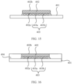
- a refrigerating apparatus 601 and the supporting part 501a shown in FIG. 13 may apply an external force to an edge of the substrate 401, to further reduce the warping degree of the substrate 401. This reduces the circuit faults caused by the deterioration in the waterproof performance and the poor contact.
- the outer side surface of the molding part 404 is attached to an inner side surface of the supporting part 501a.
- two surfaces other than two surfaces opposite to the substrate 401 are side surfaces.
- a side surface having a smaller distance from the side surface of the chip 402 is the inner side surface of the supporting part 501a.
- the outer side surface of the molding part 404 is attached to the inner side surface of the supporting part 501a, to avoid a case in which the refrigerating medium penetrates into a bonding adhesive 501b from a position between the molding part 404 and the supporting part 501a to cause failure of the bonding adhesive 501b and cause leakage of the refrigerating medium. This further improves the reliability of the chip 402.
- the supporting part 501a may be bonded to the substrate 401 by using the bonding adhesive 501b.
- the supporting part 501a and the bonding adhesive 501b may form an enclosure dam 501.
- the enclosure dam 501 may be used to limit a thermosetting material for forming the molding part 404 in the process of forming the molding part 404.
- the outer side surface of the molding part 404 may alternatively be attached to an inner side surface of the bonding adhesive 501b.
- the inner side surface of the bonding adhesive 501b is a side surface that is of the bonding adhesive 501b and that is close to the substrate 401
- an outer side surface of the bonding adhesive 501b is a side surface that is of the bonding adhesive 501b and that is close to the substrate 401.
- the supporting part 501a may be made of a metal material, for example, copper alloy or stainless steel.
- the bonding adhesive 501b may also be referred to as an AD bonding adhesive.
- the bonding adhesive 501b in this embodiment of this application may be implemented by using an existing material having a bonding function. Details are not described herein.
- the surface that is of the supporting part 501a and that is away from the substrate 401 is higher than the surface that is of the chip 402 and that is away from the substrate 401, may be lower than the surface that is of the chip 402 and that is away from the substrate 401, or may be flush with the surface that is of the chip 402 and that is away from the substrate.
- the upper surface of the supporting part 501a is behigher than the upper surface of the chip 402, may be lower than the upper surface of the chip 402, or may be flush with the upper surface of the chip 402 in height.
- the surface that is of the supporting part 501a and that is away from the substrate 401 may be flush with the second surface 402b of the chip 402.
- the upper surface of the supporting part 501a is flush with the upper surface of the chip 402.
- a distance between the surface that is of the supporting part 501a and that is away from the substrate 401 and the substrate 401 may be equal to the distance between the second surface 402b of the chip 402 and the substrate 401.
- a distance between the upper surface of the supporting part 501a and the substrate 401 may be equal to the distance between the upper surface of the chip 402 and the substrate 401.
- the supporting part 501a may form the enclosure dam 501, to form the molding part 404.
- the distance between the second surface 402b of the chip 402 and the substrate 401 is A
- the distance between the surface that is of the supporting part 501a and that is away from the substrate 401 and the substrate 401 is also A.
- the surface that is of the supporting part 501a and that is away from the substrate 401 is higher than the second surface 402b of the chip 402.
- the upper surface of the supporting part 501a is higher than the upper surface of the chip 402.
- a distance between the surface that is of the supporting part 501a and that is away from the substrate 401 and the substrate 401 may be greater than the distance between the second surface 402b of the chip 402 and the substrate 401.
- the distance between the upper surface of the supporting part 501a and the substrate 401 may be greater than the distance between the upper surface of the chip 402 and the substrate 401.
- the distance between the surface that is of the supporting part 501a and that is away from the substrate 401 and the substrate 401 is the height of the surface that is of the supporting part 501a and that is away from the substrate 401 relative to the upper surface of the substrate 401.
- pressure can be better applied to the substrate 401 by using the supporting part 501a, to further reduce the warping degree of the substrate 401.
- This further improves the waterproof performance of the chip 402 and alleviates a problem of poor contact between electronic components caused by warping of the substrate 401.
- the supporting part 501a may form the enclosure dam 501, to form the molding part 404.
- A is less than D.
- the surface that is of the supporting part 501a and that is away from the substrate 401 may be lower than the second surface 402b of the chip 402.
- the upper surface of the supporting part 501a may be lower than the upper surface of the chip 402.
- a distance between the surface that is of the supporting part 501a and that is away from the substrate 401 and the substrate 401 may be less than the distance between the second surface 402b of the chip 402 and the substrate 401.
- the distance between the upper surface of the supporting part 501a and the substrate 401 may be less than the distance between the upper surface of the chip 402 and the substrate 401. In this way, operations, for example, grinding the molding part 404 or the chip 402, can be more conveniently performed, to improve efficiency.
- A is larger than E.
- the molding part 404 may extend to the surface that is of the supporting part 501a and that is away from the substrate 401, and cover the surface that is of the supporting part 501a and that is away from the substrate 401.
- the surface that is of the supporting part 501a and that is away from the substrate 401 may be flush with the surface that is of the molding part 404 and that is away from the substrate 401.
- the upper surface of the supporting part 501a may be flush with the upper surface of the chip 402.
- the surface that is of the supporting part 501a and that is away from the substrate 401 may be higher than the surface that is of the molding part 404 and that is away from the substrate 401.
- the upper surface of the supporting part 501a may be higher than the upper surface of the chip 402.
- the surface that is of the supporting part 501a and that is away from the substrate 401 may be lower than the surface that is of the molding part 404 and that is away from the substrate 401.
- the upper surface of the supporting part 501a may be lower than the upper surface of the chip 402.
- a height of the upper surface of the supporting part 501a (where the supporting part 501a exists and the upper surface of the supporting part 501a is not covered by the molding part 404) or the molding part 404 (where the supporting part 501a does not exist or the upper surface of the supporting part 501a is covered by the molding part 404) may match the refrigerating apparatus 601 shown in FIG. 12 not encompassed by the subject-matter of the claims but considered useful for understanding the invention or FIG. 13 , so that an accommodation cavity 604 shown in FIG. 12 or FIG. 13 is large enough to accommodate sufficient refrigerants.
- the supporting part 501a or the molding part 404 may further fasten the chip 402, to avoid deformation of the substrate 401 and the chip 402.
- the supporting part 501a may also be disposed.
- the supporting part 501a may also be disposed.
- any chip package structure 400 in FIG. 5 to FIG. 7 or FIG. 9 to FIG. 11 may further include the refrigerating apparatus 601.
- the refrigerating apparatus 601 has a liquid inlet 601a, a liquid return port 601b, and a sprinkler-shaped flow channel 601c.
- the accommodation cavity 604 for accommodating a refrigerant is formed between the sprinkler-shaped flow channel 601c, the liquid return port 601b, and the waterproof layer 405.
- the accommodation cavity 604 covers at least areas that are on the waterproof layer 405 and that correspond to the second surface 402b of the chip 402.
- the liquid inlet 601a is in communication with the sprinkler-shaped flow channel 601c
- the sprinkler-shaped flow channel 601c is in communication with the accommodation cavity 604, and the accommodation cavity 604 is in communication with the liquid return port 601b.
- the chip 402 when the chip 402 works, heat generated is conducted to the second surface 402b of the chip 402, and is further conducted to the waterproof layer 405.
- the liquid inlet 601a and the liquid return port 601b of the refrigerating apparatus 601 are connected to a liquid supply system (not shown in FIG. 13 ) of the refrigerating medium.
- the refrigerating medium is injected into the sprinkler-shaped flow channel 601c through the liquid inlet 601a of the refrigerating apparatus 601, and then enters the accommodation cavity 604 through the sprinkler-shaped flow channel 601c.
- the refrigerating medium that enters the accommodation cavity 604 performs heat exchange with the waterproof layer 405, to absorb the heat generated by the chip 402. After absorbing the heat, the refrigerating medium flows out of the accommodation cavity 604 through the liquid return port 601b of the refrigerating apparatus 601, to transfer the heat out of the chip package structure 400, and implement heat dissipation of the chip 402.
- heat dissipation can be implemented on the second surface 402b of the chip 402, and the first pins 403a may be arranged in all the areas corresponding to the second surface 402b, without a limitation. All the areas corresponding to the second surface 402b may be areas at which the second surface 402b is projected in a direction perpendicular to the second surface 402b.
- a sealing kit 603 may be further disposed between the refrigerating apparatus 601 and the waterproof layer 405.
- S1401 Form, on the substrate 401, the molding part 404 that surrounds a chip 402.
- connection structure of the substrate 401, a first pin layer 403, and the chip 402 is shown in FIG. 15 .
- the chip 402 is disposed on the substrate 401, and the first pin layer 403 is disposed between the chip 402 and the substrate 401.
- the first pin layer 403, and the chip 402 refer to a connection manner of the substrate 401, the first pin layer 403, and the chip 402 in a conventional technology.
- Manner 1 not encompassed by the subject-matter of the claims but considered useful for understanding the invention: Glue dispensing and curing are directly performed to form the molding part 404.
- the molding part 404 that surrounds a side surface of the chip 402 and a side surface of the first pin layer 403 is formed through the glue dispensing and curing process.
- an outer side surface or an upper surface of the molding part 404 may be irregular.
- an operation such as grinding or polishing may be further performed on the outer side surface or the upper surface of the molding part 404.
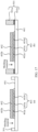
- Manner 2 The molding part 404 is formed between an enclosure dam 501 and the chip 402, as shown in (a) in FIG. 17 or (b) in FIG. 17 .
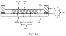
- S1401 is performed on the structure shown in (a) in FIG. 17 or (b) in FIG. 17 , to correspondingly form a structure shown in FIG. 16 or FIG. 18 .
- the forming, on the substrate 401, the molding part 404 that surrounds the chip 402 may include: forming, between the chip 402 and the enclosure dam 501 through the glue dispensing and curing process, the molding part 404 that surrounds the side surface of the chip 402 and the side surface of the first pin layer 403.
- the chip packaging method shown in FIG. 14 may further include step 1.
- Step 1 Form the enclosure dam 501 for limiting the molding part 404 on a periphery of the chip 402.
- the enclosure dam 501 is located on the substrate 401.
- the forming the enclosure dam 501 for limiting the molding part 404 on a periphery of the chip 402 may include: as shown in (a) in FIG. 17 , in the structure shown in FIG. 15 , disposing a thermosetting material on the substrate 401 around the chip 402 through the dispensing process. Then, the thermosetting material around the chip 402 is heated to a preset temperature, so that the thermosetting material is attached to the side surface of the first pin layer 403, the side surface of the chip 402, and a part of the surface of the substrate 401 that is close to the chip 401 (that is, the upper surface of the substrate 401) and that is not covered by the first pin layer 403. Then, the thermosetting material is cooled so that the thermosetting material is cured, to form the enclosure dam 501.
- a material of the enclosure dam 501 may be the same as the material of the molding part 404.
- an outer side surface or an upper surface of the enclosure dam 501 may be irregular.
- an operation such as grinding or polishing may be further performed on the outer side surface or the upper surface of the enclosure dam 501.
- the forming the enclosure dam 501 for limiting the molding part 404 on a periphery of the chip 402 may include: as shown in (b) in FIG. 17 , in the structure shown in FIG. 15 , bonding the supporting part 501a to the substrate 401 on the periphery of the chip 402 by using the bonding adhesive 501b.
- a structure including the supporting part S01a and the bonding adhesive 501b may be used as the enclosure dam 501.
- the supporting part 501a and the chip 402 are located on a same side of the substrate 401.
- grinding the surface that is of the molding part 404 and that is away from the substrate 401 and/or the second surface 402b of the chip 402 through the grinding process makes the surface that is of the molding part 404 and that is away from the substrate 401 be flush with the second surface 402b of the chip 402.
- grinding the upper surface of the molding part 404 or the upper surface of the chip 402 makes the upper surface of the molding part 404 be flush with the upper surface of the chip 402.
- the chip packaging method shown in FIG. 14 may further include step 2.
- Step 2 Connect the chip 402 to the substrate 401 to form the structure shown in FIG. 15 .
- S1402 Form the waterproof layer 405 on the second surface 402b of the chip 402 and the surface that is of the molding part 404 and that is away from the substrate 401.
- the first waterproof sublayer, the second waterproof sublayer, or the third waterproof sublayer may be formed through one of the following processes: physical vapor deposition (physical vapor deposition, PVD), chemical vapor deposition (chemical vapor deposition, CVD), and atomic layer deposition (atomic layer deposition, ALD).
- the waterproof layer 405 includes the first waterproof sublayer, the second waterproof sublayer, or the third waterproof sublayer shown in FIG. 11 .
- the first waterproof sublayer is first formed, and then the second waterproof sublayer is formed on a side that is away from the chip 402 or the molding part 404.
- the third waterproof sublayer is formed on a side that is of the second waterproof layer and that is away from the chip 402 or the molding part 404.
- waterproof layer 405 For structure descriptions and material descriptions of the waterproof layer 405, refer to the foregoing structure descriptions of the chip package structure 400. Details are not described herein again. It may be understood that the foregoing process for forming the waterproof layer 405 is merely used as an example. In an actual implementation, another process may be used based on an actual scenario.
- FIG. 5 A structure obtained after the waterproof layer 405 is formed in the structure shown in FIG. 16 is shown in FIG. 5 .
- FIG. 10 A structure obtained after the waterproof layer 405 is formed in the structure shown in FIG. 18 is shown in FIG. 10 .
- the chip packaging method shown in FIG. 14 in this embodiment of this application may further include S1403.
- S1403 Connect the substrate 401 in the chip package structure 400 to the printed circuit board 300.
- the chip package structure 400 shown in FIG. 5 performs S1403, a structure shown in (a) in FIG. 19 not encompassed by the subject-matter of the claims but considered useful for understanding the invention is formed.
- the chip package structure 400 shown in FIG. 10 performs S1403, a structure shown in (b) in FIG. 19 is formed.
- a structure formed after S1403 is performed may be further connected to the refrigerating apparatus 601.
- the structure shown in (a) in FIG. 19 is connected to the refrigerating apparatus 601 to form the structure shown in FIG. 12 .
- the structure shown in (b) in FIG. 19 is connected to the refrigerating apparatus 601, to form the structure shown in FIG. 13 .
- the chip packaging method shown in FIG. 20 may further include step 4.
- the chip packaging method shown in FIG. 20 may further include: Step 5: Connect the chip 402 to the substrate 401 to form the structure shown in FIG. 15 .
- FIG. 25 a top view of the structure shown in FIG. 24 is shown in FIG. 25 .
- the foregoing chip packaging method achieves a same technical effect as the chip package structure 400 provided in the foregoing embodiments. Details are not described herein again.
Landscapes
- Structures Or Materials For Encapsulating Or Coating Semiconductor Devices Or Solid State Devices (AREA)
Claims (10)
- Chipgehäusestruktur (400), umfassend:ein Substrat (401);einen Chip (402), der eine erste Fläche (402a) nahe dem Substrat (401) und eine zweite Fläche (402b) gegenüber der ersten Fläche (402a) aufweist;eine erste Stiftschicht (403), die eine Vielzahl von Stiften umfasst, die zwischen der ersten Fläche (402a) des Chips (402) und dem Substrat (401) angeordnet ist;ein Formteil (404), das an einem Umfang des Chips (402) und der ersten Stiftschicht (403) angeordnet ist, wobei eine Fläche das Formteils (404), die vom Substrat (401) weg weist, höher ist als die erste Fläche (402a) des Chips (402) und eine Seitenfläche der ersten Stiftschicht (403) und mindestens einen Teil einer Seitenfläche des Chips (402) bedeckt, und das Formteil (404) an der Seitenfläche des Chips (402) angebracht ist; undeine wasserdichte Schicht (405), die auf der zweiten Fläche (402b) des Chips (402) und der Fläche das Formteils (404), die vom Substrat (401) weg weist, angeordnet ist;wobei die Chipgehäusestruktur (400) ferner Folgendes umfasst:
ein Stützteil (501a), das auf dem Substrat (401) angeordnet ist, wobei das Stützteil (501a) das Formteil (404) umgibt und eine äußere Seitenfläche des Formteils (404) an einer inneren Seitenfläche des Stützteils (501a) angebracht ist, wobei eine Fläche das Stützteils (501a), die vom Substrat (401) weg weist, höher ist als die zweite Fläche (402b) des Chips (402). - Chipgehäusestruktur (400) nach Anspruch 1, wobei das Formteil (404) alle Seitenflächen des Chips (402) bedeckt und die Fläche des Formteils (404), die vom Substrat (401) weg weist, bündig mit der zweiten Fläche (402b) des Chips (402) abschließt.
- Chipgehäusestruktur (400) nach Anspruch 1, wobei die Fläche des Formteils (404), die vom Substrat (401) weg weist, tiefer ist als die zweite Fläche (402b) des Chips (402).
- Chipgehäusestruktur (400) nach einem der Ansprüche 1 bis 3, ferner umfassend:
eine Kühlvorrichtung (101, 601), die einen Flüssigkeitseinlass (101a, 601a), eine Flüssigkeitsrücklauföffnung (101c, 601b) und einen sprinklerförmigen Strömungskanal (101b, 601c) umfasst, wobei ein Aufnahmehohlraum (107, 604) zum Aufnehmen eines Kühlmittels zwischen dem sprinklerförmigen Strömungskanal (101b, 601c), der Flüssigkeitsrücklauföffnung (101c, 601b) und der wasserdichten Schicht (405) gebildet ist, der Aufnahmehohlraum (107, 604) mindestens die wasserdichte Schicht (405) bedeckt, die der zweiten Fläche (402b) des Chips (402) entspricht, der Flüssigkeitseinlass (101a, 601a) in Verbindung mit dem sprinklerförmigen Strömungskanal (101b, 601c) steht, der sprinklerförmige Strömungskanal (101b, 601c) in Verbindung mit dem Aufnahmehohlraum steht (107, 604) und der Aufnahmehohlraum (107, 604) in Verbindung mit der Flüssigkeitsrücklauföffnung (101c, 601b) steht. - Elektronische Vorrichtung, wobei die elektronische Vorrichtung eine Leiterplatte (103, 300) und mindestens eine Chipgehäusestruktur (400) nach einem der Ansprüche 1 bis 4 umfasst und die Chipgehäusestruktur (400) mit der Leiterplatte (103, 300) verbunden ist.
- Chipverpackungsverfahren, wobei das Verfahren Folgendes umfasst:Bilden eines Umschließungsdamms (501) an einem Umfang eines Chips (402) zum Begrenzen eines Formteils (404), wobei sich der Umschließungsdamm (501) auf einem Substrat (401) befindet;Bilden des Formteils (404), das den Chip (402) umgibt, auf dem Substrat (401), wobei das Bilden des Formteils (404), das den Chip (402) umgibt, auf dem Substrat (401) Folgendes umfasst:Bilden des Formteils (404) zwischen dem Umschließungsdamm (501) und dem Chip (402), und wobei der Umschließungsdamm (501) ein Stützteil (501a) ist und eine äußere Seitenfläche des Formteils (404) an einer inneren Seitenfläche des Stützteils (501a) angebracht ist, und wobei der Chip (402) auf dem Substrat (401) angeordnet ist, der Chip (402) eine erste Fläche (402a) nahe dem Substrat (401) und eine zweite Fläche (402b) gegenüber der ersten Fläche (402a) aufweist, die erste Fläche (402a) durch eine erste Stiftschicht (403) mit dem Substrat (401) verbunden ist, die erste Stiftschicht (403) eine Vielzahl von Stiften umfasst, die zwischen der ersten Fläche (402a) des Chips (402) und dem Substrat (401) angeordnet ist, eine Fläche des Formteils (404), die vom Substrat (401) weg weist, höher ist als die erste Fläche (402a) des Chips (402), das Formteil (404) eine Seitenfläche der ersten Stiftschicht (403) und mindestens einen Teil einer Seitenfläche des Chips (402) bedeckt und das Formteil (404) an der Seitenfläche des Chips (402) angebracht ist, und wobei eine Fläche des Stützteils (501a), die vom Substrat (401) weg weist, höher ist als die zweite Fläche (402b) des Chips (402); undBilden einer wasserdichten Schicht (405) auf der zweiten Fläche (402b) des Chips (402) und der Fläche des Formteils (404), die vom Substrat (401) weg weist.
- Chipverpackungsverfahren nach Anspruch 6, wobei das Formteil (404) alle Seitenflächen des Chips (402) bedeckt und die Fläche des Formteils (404), die vom Substrat (401) weg weist, bündig mit der zweiten Fläche (402b) des Chips (402) abschließt.
- Chipverpackungsverfahren nach Anspruch 6, wobei die Fläche des Formteils (404), die vom Substrat (401) weg weist, tiefer ist als die zweite Fläche (402b) des Chips (402).
- Chipverpackungsverfahren nach einem der Ansprüche 6 bis 8, wobei das Verfahren vor dem Formen eines Formteils (404), das einen Chip (402) umgibt, auf einem Substrat (401) ferner Folgendes umfasst:
Verbinden des Substrats (401) mit einer Leiterplatte (103, 300). - Chipverpackungsverfahren nach einem der Ansprüche 6 bis 8, wobei das Verfahren nach dem Bilden einer wasserdichten Schicht (405) auf der zweiten Fläche (402b) des Chips (402) und der Fläche des Formteils (404), die vom Substrat (401) weg weist, ferner Folgendes umfasst:
Verbinden des Substrats (401) mit einer Leiterplatte (103, 300).
Applications Claiming Priority (1)
| Application Number | Priority Date | Filing Date | Title |
|---|---|---|---|
| PCT/CN2021/106344 WO2023283842A1 (zh) | 2021-07-14 | 2021-07-14 | 芯片封装结构及封装方法、电子设备 |
Publications (3)
| Publication Number | Publication Date |
|---|---|
| EP4340010A1 EP4340010A1 (de) | 2024-03-20 |
| EP4340010A4 EP4340010A4 (de) | 2024-06-19 |
| EP4340010B1 true EP4340010B1 (de) | 2025-06-25 |
Family
ID=84918910
Family Applications (1)
| Application Number | Title | Priority Date | Filing Date |
|---|---|---|---|
| EP21949634.6A Active EP4340010B1 (de) | 2021-07-14 | 2021-07-14 | Chipgehäusestruktur und verpackungsverfahren und elektronische vorrichtung |
Country Status (3)
| Country | Link |
|---|---|
| EP (1) | EP4340010B1 (de) |
| CN (1) | CN117501431A (de) |
| WO (1) | WO2023283842A1 (de) |
Families Citing this family (5)
| Publication number | Priority date | Publication date | Assignee | Title |
|---|---|---|---|---|
| US12412803B2 (en) * | 2022-03-15 | 2025-09-09 | Yuci Shen | Lid allowing for a thermal interface material with fluidity in a lidded flip chip package |
| CN120600707A (zh) * | 2024-03-04 | 2025-09-05 | 华为技术有限公司 | 具有防渗透层的散热系统及电子设备 |
| CN120834094A (zh) * | 2024-04-15 | 2025-10-24 | 华为技术有限公司 | 一种射流液冷结构、其制作方法及电子设备 |
| CN120854403A (zh) * | 2024-04-28 | 2025-10-28 | 华为技术有限公司 | 一种封装结构及电子设备 |
| CN121398600A (zh) * | 2024-07-15 | 2026-01-23 | 华为技术有限公司 | 一种封装芯片、电路板组件及电子设备 |
Family Cites Families (10)
| Publication number | Priority date | Publication date | Assignee | Title |
|---|---|---|---|---|
| US7271034B2 (en) * | 2004-06-15 | 2007-09-18 | International Business Machines Corporation | Semiconductor device with a high thermal dissipation efficiency |
| CN1885528A (zh) * | 2005-06-20 | 2006-12-27 | 南茂科技股份有限公司 | 倒装片封装结构 |
| US7731079B2 (en) * | 2008-06-20 | 2010-06-08 | International Business Machines Corporation | Cooling apparatus and method of fabrication thereof with a cold plate formed in situ on a surface to be cooled |
| US10879194B2 (en) * | 2017-05-25 | 2020-12-29 | Taiwan Semiconductor Manufacturing Company Ltd. | Semiconductor device package and method of manufacturing the same |
| CN110197793A (zh) * | 2018-02-24 | 2019-09-03 | 华为技术有限公司 | 一种芯片及封装方法 |
| US20190287931A1 (en) * | 2018-03-15 | 2019-09-19 | Novatek Microelectronics Corp. | Chip on film package |
| CN211208425U (zh) * | 2019-09-17 | 2020-08-07 | 苏州捷研芯电子科技有限公司 | 适用于rf器件的封装结构 |
| US11355418B2 (en) * | 2019-09-29 | 2022-06-07 | Taiwan Semiconductor Manufacturing Company, Ltd. | Package structure and manufacturing method thereof |
| US11328975B2 (en) * | 2019-11-26 | 2022-05-10 | Taiwan Semiconductor Manufacturing Company, Ltd. | Semiconductor device |
| WO2021119930A1 (zh) * | 2019-12-16 | 2021-06-24 | 华为技术有限公司 | 芯片封装及其制作方法 |
-
2021
- 2021-07-14 CN CN202180099524.9A patent/CN117501431A/zh active Pending
- 2021-07-14 WO PCT/CN2021/106344 patent/WO2023283842A1/zh not_active Ceased
- 2021-07-14 EP EP21949634.6A patent/EP4340010B1/de active Active
Also Published As
| Publication number | Publication date |
|---|---|
| CN117501431A (zh) | 2024-02-02 |
| WO2023283842A1 (zh) | 2023-01-19 |
| EP4340010A1 (de) | 2024-03-20 |
| EP4340010A4 (de) | 2024-06-19 |
Similar Documents
| Publication | Publication Date | Title |
|---|---|---|
| EP4340010B1 (de) | Chipgehäusestruktur und verpackungsverfahren und elektronische vorrichtung | |
| US12278156B2 (en) | Semiconductor package | |
| US11488936B2 (en) | Stacked silicon package assembly having vertical thermal management | |
| US11177193B2 (en) | Reservoir structure and system forming gap for liquid thermal interface material | |
| US7723160B2 (en) | Thermal interface structure with integrated liquid cooling and methods | |
| US12550726B2 (en) | Package chip having a heat sink and method for manufacturing package chip | |
| JP5414349B2 (ja) | 電子装置 | |
| US11869824B2 (en) | Thermal interface structures for integrated circuit packages | |
| US9386685B2 (en) | Interposer and semiconductor module using the same | |
| US8779582B2 (en) | Compliant heat spreader for flip chip packaging having thermally-conductive element with different metal material areas | |
| US7671466B2 (en) | Semiconductor package having heat dissipating device with cooling fluid | |
| US20060226538A1 (en) | Interposer and semiconductor device employing same, and method for manufacturing semiconductor device | |
| WO2007041109A1 (en) | Microelectronic package having direct contact heat spreader and method of manufacturing same | |
| US20240371794A1 (en) | Semiconductor device and manufacturing method thereof | |
| US12272619B2 (en) | Direct liquid cooling with O-ring sealing | |
| CN1949486B (zh) | 半导体装置、半导体装置的制作方法 | |
| WO2005006433A2 (en) | Mold compound cap in a flip chip multi-matrix array package and process of making same | |
| US20060261469A1 (en) | Sealing membrane for thermal interface material | |
| WO2024206743A1 (en) | Embedded cooling systems for device packages and methods of cooling packaged devices | |
| US7221571B2 (en) | Package unit, printed board having the same, and electronic apparatus having the printed board | |
| US11189541B2 (en) | Semiconductor package | |
| US6441499B1 (en) | Thin form factor flip chip ball grid array | |
| US6238954B1 (en) | COF packaged semiconductor | |
| TW202418932A (zh) | 可從異質整合最大化提高熱傳遞之混合式散熱系統 | |
| US20060118947A1 (en) | Thermal expansion compensating flip chip ball grid array package structure |
Legal Events
| Date | Code | Title | Description |
|---|---|---|---|
| STAA | Information on the status of an ep patent application or granted ep patent |
Free format text: STATUS: THE INTERNATIONAL PUBLICATION HAS BEEN MADE |
|
| PUAI | Public reference made under article 153(3) epc to a published international application that has entered the european phase |
Free format text: ORIGINAL CODE: 0009012 |
|
| STAA | Information on the status of an ep patent application or granted ep patent |
Free format text: STATUS: REQUEST FOR EXAMINATION WAS MADE |
|
| 17P | Request for examination filed |
Effective date: 20231214 |
|
| AK | Designated contracting states |
Kind code of ref document: A1 Designated state(s): AL AT BE BG CH CY CZ DE DK EE ES FI FR GB GR HR HU IE IS IT LI LT LU LV MC MK MT NL NO PL PT RO RS SE SI SK SM TR |
|
| REG | Reference to a national code |
Ref legal event code: R079 Ref country code: DE Ref legal event code: R079 Ref document number: 602021033125 Country of ref document: DE Free format text: PREVIOUS MAIN CLASS: H01L0023000000 Ipc: H01L0023310000 |
|
| A4 | Supplementary search report drawn up and despatched |
Effective date: 20240517 |
|
| RIC1 | Information provided on ipc code assigned before grant |
Ipc: H01L 23/00 20060101ALN20240513BHEP Ipc: H01L 23/473 20060101ALI20240513BHEP Ipc: H01L 23/40 20060101ALI20240513BHEP Ipc: H01L 23/31 20060101AFI20240513BHEP |
|
| DAV | Request for validation of the european patent (deleted) | ||
| DAX | Request for extension of the european patent (deleted) | ||
| GRAP | Despatch of communication of intention to grant a patent |
Free format text: ORIGINAL CODE: EPIDOSNIGR1 |
|
| STAA | Information on the status of an ep patent application or granted ep patent |
Free format text: STATUS: GRANT OF PATENT IS INTENDED |
|
| RIC1 | Information provided on ipc code assigned before grant |
Ipc: H01L 23/00 20060101ALN20250130BHEP Ipc: H01L 23/473 20060101ALI20250130BHEP Ipc: H01L 23/40 20060101ALI20250130BHEP Ipc: H01L 23/31 20060101AFI20250130BHEP |
|
| RIC1 | Information provided on ipc code assigned before grant |
Ipc: H01L 23/00 20060101ALN20250204BHEP Ipc: H01L 23/473 20060101ALI20250204BHEP Ipc: H01L 23/40 20060101ALI20250204BHEP Ipc: H01L 23/31 20060101AFI20250204BHEP |
|
| INTG | Intention to grant announced |
Effective date: 20250213 |
|
| P01 | Opt-out of the competence of the unified patent court (upc) registered |
Free format text: CASE NUMBER: APP_10172/2025 Effective date: 20250227 |
|
| GRAS | Grant fee paid |
Free format text: ORIGINAL CODE: EPIDOSNIGR3 |
|
| GRAA | (expected) grant |
Free format text: ORIGINAL CODE: 0009210 |
|
| STAA | Information on the status of an ep patent application or granted ep patent |
Free format text: STATUS: THE PATENT HAS BEEN GRANTED |
|
| AK | Designated contracting states |
Kind code of ref document: B1 Designated state(s): AL AT BE BG CH CY CZ DE DK EE ES FI FR GB GR HR HU IE IS IT LI LT LU LV MC MK MT NL NO PL PT RO RS SE SI SK SM TR |
|
| REG | Reference to a national code |
Ref country code: GB Ref legal event code: FG4D |
|
| REG | Reference to a national code |
Ref country code: CH Ref legal event code: EP |
|
| REG | Reference to a national code |
Ref country code: CH Ref legal event code: EP |
|
| REG | Reference to a national code |
Ref country code: IE Ref legal event code: FG4D |
|
| REG | Reference to a national code |
Ref country code: DE Ref legal event code: R096 Ref document number: 602021033125 Country of ref document: DE |
|
| PG25 | Lapsed in a contracting state [announced via postgrant information from national office to epo] |
Ref country code: FI Free format text: LAPSE BECAUSE OF FAILURE TO SUBMIT A TRANSLATION OF THE DESCRIPTION OR TO PAY THE FEE WITHIN THE PRESCRIBED TIME-LIMIT Effective date: 20250625 |
|
| PGFP | Annual fee paid to national office [announced via postgrant information from national office to epo] |
Ref country code: DE Payment date: 20250708 Year of fee payment: 5 |
|
| REG | Reference to a national code |
Ref country code: LT Ref legal event code: MG9D |
|
| PG25 | Lapsed in a contracting state [announced via postgrant information from national office to epo] |
Ref country code: GR Free format text: LAPSE BECAUSE OF FAILURE TO SUBMIT A TRANSLATION OF THE DESCRIPTION OR TO PAY THE FEE WITHIN THE PRESCRIBED TIME-LIMIT Effective date: 20250926 Ref country code: NO Free format text: LAPSE BECAUSE OF FAILURE TO SUBMIT A TRANSLATION OF THE DESCRIPTION OR TO PAY THE FEE WITHIN THE PRESCRIBED TIME-LIMIT Effective date: 20250925 |
|
| PG25 | Lapsed in a contracting state [announced via postgrant information from national office to epo] |
Ref country code: BG Free format text: LAPSE BECAUSE OF FAILURE TO SUBMIT A TRANSLATION OF THE DESCRIPTION OR TO PAY THE FEE WITHIN THE PRESCRIBED TIME-LIMIT Effective date: 20250625 |
|
| PG25 | Lapsed in a contracting state [announced via postgrant information from national office to epo] |
Ref country code: HR Free format text: LAPSE BECAUSE OF FAILURE TO SUBMIT A TRANSLATION OF THE DESCRIPTION OR TO PAY THE FEE WITHIN THE PRESCRIBED TIME-LIMIT Effective date: 20250625 |
|
| PGFP | Annual fee paid to national office [announced via postgrant information from national office to epo] |
Ref country code: FR Payment date: 20250708 Year of fee payment: 5 Ref country code: AT Payment date: 20251020 Year of fee payment: 5 |
|
| PG25 | Lapsed in a contracting state [announced via postgrant information from national office to epo] |
Ref country code: RS Free format text: LAPSE BECAUSE OF FAILURE TO SUBMIT A TRANSLATION OF THE DESCRIPTION OR TO PAY THE FEE WITHIN THE PRESCRIBED TIME-LIMIT Effective date: 20250925 |
|
| PGFP | Annual fee paid to national office [announced via postgrant information from national office to epo] |
Ref country code: IE Payment date: 20250709 Year of fee payment: 5 |
|
| PG25 | Lapsed in a contracting state [announced via postgrant information from national office to epo] |
Ref country code: LV Free format text: LAPSE BECAUSE OF FAILURE TO SUBMIT A TRANSLATION OF THE DESCRIPTION OR TO PAY THE FEE WITHIN THE PRESCRIBED TIME-LIMIT Effective date: 20250625 |
|
| REG | Reference to a national code |
Ref country code: NL Ref legal event code: MP Effective date: 20250625 |
|
| PG25 | Lapsed in a contracting state [announced via postgrant information from national office to epo] |
Ref country code: NL Free format text: LAPSE BECAUSE OF FAILURE TO SUBMIT A TRANSLATION OF THE DESCRIPTION OR TO PAY THE FEE WITHIN THE PRESCRIBED TIME-LIMIT Effective date: 20250625 |
|
| REG | Reference to a national code |
Ref country code: DE Ref legal event code: R079 Ref document number: 602021033125 Country of ref document: DE Free format text: PREVIOUS MAIN CLASS: H01L0023310000 Ipc: H10W0074100000 |
|
| PG25 | Lapsed in a contracting state [announced via postgrant information from national office to epo] |
Ref country code: PT Free format text: LAPSE BECAUSE OF FAILURE TO SUBMIT A TRANSLATION OF THE DESCRIPTION OR TO PAY THE FEE WITHIN THE PRESCRIBED TIME-LIMIT Effective date: 20251027 |
|
| REG | Reference to a national code |
Ref country code: AT Ref legal event code: MK05 Ref document number: 1807492 Country of ref document: AT Kind code of ref document: T Effective date: 20250625 |
|
| PG25 | Lapsed in a contracting state [announced via postgrant information from national office to epo] |
Ref country code: IS Free format text: LAPSE BECAUSE OF FAILURE TO SUBMIT A TRANSLATION OF THE DESCRIPTION OR TO PAY THE FEE WITHIN THE PRESCRIBED TIME-LIMIT Effective date: 20251025 |
|
| PG25 | Lapsed in a contracting state [announced via postgrant information from national office to epo] |
Ref country code: SM Free format text: LAPSE BECAUSE OF FAILURE TO SUBMIT A TRANSLATION OF THE DESCRIPTION OR TO PAY THE FEE WITHIN THE PRESCRIBED TIME-LIMIT Effective date: 20250625 Ref country code: AT Free format text: LAPSE BECAUSE OF FAILURE TO SUBMIT A TRANSLATION OF THE DESCRIPTION OR TO PAY THE FEE WITHIN THE PRESCRIBED TIME-LIMIT Effective date: 20250625 |
|
| PG25 | Lapsed in a contracting state [announced via postgrant information from national office to epo] |
Ref country code: CZ Free format text: LAPSE BECAUSE OF FAILURE TO SUBMIT A TRANSLATION OF THE DESCRIPTION OR TO PAY THE FEE WITHIN THE PRESCRIBED TIME-LIMIT Effective date: 20250625 |
|
| PG25 | Lapsed in a contracting state [announced via postgrant information from national office to epo] |
Ref country code: PL Free format text: LAPSE BECAUSE OF FAILURE TO SUBMIT A TRANSLATION OF THE DESCRIPTION OR TO PAY THE FEE WITHIN THE PRESCRIBED TIME-LIMIT Effective date: 20250625 |
|
| PG25 | Lapsed in a contracting state [announced via postgrant information from national office to epo] |
Ref country code: EE Free format text: LAPSE BECAUSE OF FAILURE TO SUBMIT A TRANSLATION OF THE DESCRIPTION OR TO PAY THE FEE WITHIN THE PRESCRIBED TIME-LIMIT Effective date: 20250625 |
|
| PG25 | Lapsed in a contracting state [announced via postgrant information from national office to epo] |
Ref country code: SK Free format text: LAPSE BECAUSE OF FAILURE TO SUBMIT A TRANSLATION OF THE DESCRIPTION OR TO PAY THE FEE WITHIN THE PRESCRIBED TIME-LIMIT Effective date: 20250625 |
|
| PG25 | Lapsed in a contracting state [announced via postgrant information from national office to epo] |
Ref country code: ES Free format text: LAPSE BECAUSE OF FAILURE TO SUBMIT A TRANSLATION OF THE DESCRIPTION OR TO PAY THE FEE WITHIN THE PRESCRIBED TIME-LIMIT Effective date: 20250625 |
|
| REG | Reference to a national code |
Ref country code: CH Ref legal event code: H13 Free format text: ST27 STATUS EVENT CODE: U-0-0-H10-H13 (AS PROVIDED BY THE NATIONAL OFFICE) Effective date: 20260224 |
|
| PG25 | Lapsed in a contracting state [announced via postgrant information from national office to epo] |
Ref country code: RO Free format text: LAPSE BECAUSE OF FAILURE TO SUBMIT A TRANSLATION OF THE DESCRIPTION OR TO PAY THE FEE WITHIN THE PRESCRIBED TIME-LIMIT Effective date: 20250625 Ref country code: LU Free format text: LAPSE BECAUSE OF NON-PAYMENT OF DUE FEES Effective date: 20250714 |
|
| REG | Reference to a national code |
Ref country code: BE Ref legal event code: MM Effective date: 20250731 |
|
| PG25 | Lapsed in a contracting state [announced via postgrant information from national office to epo] |
Ref country code: MC Free format text: LAPSE BECAUSE OF FAILURE TO SUBMIT A TRANSLATION OF THE DESCRIPTION OR TO PAY THE FEE WITHIN THE PRESCRIBED TIME-LIMIT Effective date: 20250625 |
|
| PG25 | Lapsed in a contracting state [announced via postgrant information from national office to epo] |
Ref country code: DK Free format text: LAPSE BECAUSE OF FAILURE TO SUBMIT A TRANSLATION OF THE DESCRIPTION OR TO PAY THE FEE WITHIN THE PRESCRIBED TIME-LIMIT Effective date: 20250625 |
|
| PG25 | Lapsed in a contracting state [announced via postgrant information from national office to epo] |
Ref country code: BE Free format text: LAPSE BECAUSE OF NON-PAYMENT OF DUE FEES Effective date: 20250731 Ref country code: IT Free format text: LAPSE BECAUSE OF FAILURE TO SUBMIT A TRANSLATION OF THE DESCRIPTION OR TO PAY THE FEE WITHIN THE PRESCRIBED TIME-LIMIT Effective date: 20250625 |