EP4339460A1 - Pump device - Google Patents
Pump device Download PDFInfo
- Publication number
- EP4339460A1 EP4339460A1 EP22807189.0A EP22807189A EP4339460A1 EP 4339460 A1 EP4339460 A1 EP 4339460A1 EP 22807189 A EP22807189 A EP 22807189A EP 4339460 A1 EP4339460 A1 EP 4339460A1
- Authority
- EP
- European Patent Office
- Prior art keywords
- pump
- busbar
- motor
- rotor
- surface area
- Prior art date
- Legal status (The legal status is an assumption and is not a legal conclusion. Google has not performed a legal analysis and makes no representation as to the accuracy of the status listed.)
- Withdrawn
Links
Images



Classifications
-
- H—ELECTRICITY
- H02—GENERATION; CONVERSION OR DISTRIBUTION OF ELECTRIC POWER
- H02K—DYNAMO-ELECTRIC MACHINES
- H02K11/00—Structural association of dynamo-electric machines with electric components or with devices for shielding, monitoring or protection
- H02K11/30—Structural association with control circuits or drive circuits
- H02K11/33—Drive circuits, e.g. power electronics
-
- F—MECHANICAL ENGINEERING; LIGHTING; HEATING; WEAPONS; BLASTING
- F04—POSITIVE - DISPLACEMENT MACHINES FOR LIQUIDS; PUMPS FOR LIQUIDS OR ELASTIC FLUIDS
- F04C—ROTARY-PISTON, OR OSCILLATING-PISTON, POSITIVE-DISPLACEMENT MACHINES FOR LIQUIDS; ROTARY-PISTON, OR OSCILLATING-PISTON, POSITIVE-DISPLACEMENT PUMPS
- F04C15/00—Component parts, details or accessories of machines, pumps or pumping installations, not provided for in groups F04C2/00 - F04C14/00
-
- F—MECHANICAL ENGINEERING; LIGHTING; HEATING; WEAPONS; BLASTING
- F04—POSITIVE - DISPLACEMENT MACHINES FOR LIQUIDS; PUMPS FOR LIQUIDS OR ELASTIC FLUIDS
- F04C—ROTARY-PISTON, OR OSCILLATING-PISTON, POSITIVE-DISPLACEMENT MACHINES FOR LIQUIDS; ROTARY-PISTON, OR OSCILLATING-PISTON, POSITIVE-DISPLACEMENT PUMPS
- F04C15/00—Component parts, details or accessories of machines, pumps or pumping installations, not provided for in groups F04C2/00 - F04C14/00
- F04C15/0057—Driving elements, brakes, couplings, transmission specially adapted for machines or pumps
- F04C15/008—Prime movers
-
- F—MECHANICAL ENGINEERING; LIGHTING; HEATING; WEAPONS; BLASTING
- F04—POSITIVE - DISPLACEMENT MACHINES FOR LIQUIDS; PUMPS FOR LIQUIDS OR ELASTIC FLUIDS
- F04C—ROTARY-PISTON, OR OSCILLATING-PISTON, POSITIVE-DISPLACEMENT MACHINES FOR LIQUIDS; ROTARY-PISTON, OR OSCILLATING-PISTON, POSITIVE-DISPLACEMENT PUMPS
- F04C15/00—Component parts, details or accessories of machines, pumps or pumping installations, not provided for in groups F04C2/00 - F04C14/00
- F04C15/0096—Heating; Cooling
-
- F—MECHANICAL ENGINEERING; LIGHTING; HEATING; WEAPONS; BLASTING
- F04—POSITIVE - DISPLACEMENT MACHINES FOR LIQUIDS; PUMPS FOR LIQUIDS OR ELASTIC FLUIDS
- F04C—ROTARY-PISTON, OR OSCILLATING-PISTON, POSITIVE-DISPLACEMENT MACHINES FOR LIQUIDS; ROTARY-PISTON, OR OSCILLATING-PISTON, POSITIVE-DISPLACEMENT PUMPS
- F04C2/00—Rotary-piston machines or pumps
- F04C2/08—Rotary-piston machines or pumps of intermeshing-engagement type, i.e. with engagement of co-operating members similar to that of toothed gearing
- F04C2/082—Details specially related to intermeshing engagement type machines or pumps
- F04C2/084—Toothed wheels
-
- F—MECHANICAL ENGINEERING; LIGHTING; HEATING; WEAPONS; BLASTING
- F04—POSITIVE - DISPLACEMENT MACHINES FOR LIQUIDS; PUMPS FOR LIQUIDS OR ELASTIC FLUIDS
- F04C—ROTARY-PISTON, OR OSCILLATING-PISTON, POSITIVE-DISPLACEMENT MACHINES FOR LIQUIDS; ROTARY-PISTON, OR OSCILLATING-PISTON, POSITIVE-DISPLACEMENT PUMPS
- F04C2/00—Rotary-piston machines or pumps
- F04C2/08—Rotary-piston machines or pumps of intermeshing-engagement type, i.e. with engagement of co-operating members similar to that of toothed gearing
- F04C2/10—Rotary-piston machines or pumps of intermeshing-engagement type, i.e. with engagement of co-operating members similar to that of toothed gearing of internal-axis type with the outer member having more teeth or tooth-equivalents, e.g. rollers, than the inner member
- F04C2/102—Rotary-piston machines or pumps of intermeshing-engagement type, i.e. with engagement of co-operating members similar to that of toothed gearing of internal-axis type with the outer member having more teeth or tooth-equivalents, e.g. rollers, than the inner member the two members rotating simultaneously around their respective axes
-
- H—ELECTRICITY
- H02—GENERATION; CONVERSION OR DISTRIBUTION OF ELECTRIC POWER
- H02K—DYNAMO-ELECTRIC MACHINES
- H02K21/00—Synchronous motors having permanent magnets; Synchronous generators having permanent magnets
- H02K21/12—Synchronous motors having permanent magnets; Synchronous generators having permanent magnets with stationary armatures and rotating magnets
- H02K21/14—Synchronous motors having permanent magnets; Synchronous generators having permanent magnets with stationary armatures and rotating magnets with magnets rotating within the armatures
-
- H—ELECTRICITY
- H02—GENERATION; CONVERSION OR DISTRIBUTION OF ELECTRIC POWER
- H02K—DYNAMO-ELECTRIC MACHINES
- H02K3/00—Details of windings
- H02K3/46—Fastening of windings on the stator or rotor structure
- H02K3/50—Fastening of winding heads, equalising connectors, or connections thereto
-
- H—ELECTRICITY
- H02—GENERATION; CONVERSION OR DISTRIBUTION OF ELECTRIC POWER
- H02K—DYNAMO-ELECTRIC MACHINES
- H02K3/00—Details of windings
- H02K3/46—Fastening of windings on the stator or rotor structure
- H02K3/52—Fastening salient pole windings or connections thereto
- H02K3/521—Fastening salient pole windings or connections thereto applicable to stators only
- H02K3/522—Fastening salient pole windings or connections thereto applicable to stators only for generally annular cores with salient poles
-
- H—ELECTRICITY
- H02—GENERATION; CONVERSION OR DISTRIBUTION OF ELECTRIC POWER
- H02K—DYNAMO-ELECTRIC MACHINES
- H02K9/00—Arrangements for cooling or ventilating
- H02K9/19—Arrangements for cooling or ventilating for machines with closed casing and closed-circuit cooling using a liquid cooling medium, e.g. oil
- H02K9/197—Arrangements for cooling or ventilating for machines with closed casing and closed-circuit cooling using a liquid cooling medium, e.g. oil in which the rotor or stator space is fluid-tight, e.g. to provide for different cooling media for rotor and stator
-
- H—ELECTRICITY
- H02—GENERATION; CONVERSION OR DISTRIBUTION OF ELECTRIC POWER
- H02K—DYNAMO-ELECTRIC MACHINES
- H02K9/00—Arrangements for cooling or ventilating
- H02K9/22—Arrangements for cooling or ventilating by solid heat conducting material embedded in, or arranged in contact with, the stator or rotor, e.g. heat bridges
- H02K9/227—Heat sinks
-
- F—MECHANICAL ENGINEERING; LIGHTING; HEATING; WEAPONS; BLASTING
- F04—POSITIVE - DISPLACEMENT MACHINES FOR LIQUIDS; PUMPS FOR LIQUIDS OR ELASTIC FLUIDS
- F04C—ROTARY-PISTON, OR OSCILLATING-PISTON, POSITIVE-DISPLACEMENT MACHINES FOR LIQUIDS; ROTARY-PISTON, OR OSCILLATING-PISTON, POSITIVE-DISPLACEMENT PUMPS
- F04C2240/00—Components
- F04C2240/30—Casings or housings
-
- F—MECHANICAL ENGINEERING; LIGHTING; HEATING; WEAPONS; BLASTING
- F04—POSITIVE - DISPLACEMENT MACHINES FOR LIQUIDS; PUMPS FOR LIQUIDS OR ELASTIC FLUIDS
- F04C—ROTARY-PISTON, OR OSCILLATING-PISTON, POSITIVE-DISPLACEMENT MACHINES FOR LIQUIDS; ROTARY-PISTON, OR OSCILLATING-PISTON, POSITIVE-DISPLACEMENT PUMPS
- F04C2240/00—Components
- F04C2240/40—Electric motor
-
- F—MECHANICAL ENGINEERING; LIGHTING; HEATING; WEAPONS; BLASTING
- F04—POSITIVE - DISPLACEMENT MACHINES FOR LIQUIDS; PUMPS FOR LIQUIDS OR ELASTIC FLUIDS
- F04C—ROTARY-PISTON, OR OSCILLATING-PISTON, POSITIVE-DISPLACEMENT MACHINES FOR LIQUIDS; ROTARY-PISTON, OR OSCILLATING-PISTON, POSITIVE-DISPLACEMENT PUMPS
- F04C2240/00—Components
- F04C2240/80—Other components
- F04C2240/803—Electric connectors or cables; Fittings therefor
-
- F—MECHANICAL ENGINEERING; LIGHTING; HEATING; WEAPONS; BLASTING
- F04—POSITIVE - DISPLACEMENT MACHINES FOR LIQUIDS; PUMPS FOR LIQUIDS OR ELASTIC FLUIDS
- F04C—ROTARY-PISTON, OR OSCILLATING-PISTON, POSITIVE-DISPLACEMENT MACHINES FOR LIQUIDS; ROTARY-PISTON, OR OSCILLATING-PISTON, POSITIVE-DISPLACEMENT PUMPS
- F04C2240/00—Components
- F04C2240/80—Other components
- F04C2240/808—Electronic circuits (e.g. inverters) installed inside the machine
-
- H—ELECTRICITY
- H02—GENERATION; CONVERSION OR DISTRIBUTION OF ELECTRIC POWER
- H02K—DYNAMO-ELECTRIC MACHINES
- H02K2203/00—Specific aspects not provided for in the other groups of this subclass relating to the windings
- H02K2203/09—Machines characterised by wiring elements other than wires, e.g. bus rings, for connecting the winding terminations
-
- H—ELECTRICITY
- H02—GENERATION; CONVERSION OR DISTRIBUTION OF ELECTRIC POWER
- H02K—DYNAMO-ELECTRIC MACHINES
- H02K2211/00—Specific aspects not provided for in the other groups of this subclass relating to measuring or protective devices or electric components
- H02K2211/03—Machines characterised by circuit boards, e.g. pcb
Definitions
- the present invention relates to a pump device including an electric motor and a pump.
- the electric pump described in Patent Document 1 includes a pump unit including a suction-side oil passage communicating with a suction port and a discharge-side oil passage communicating with a discharge port, and a motor unit including a stator including a stator core and a motor case to which the stator is attached.
- a gap is formed between the inner peripheral surface of the motor case and the outer peripheral surface of the stator core. The gap communicates with the suction-side oil passage and the discharge-side oil passage.
- oil is sent from the suction-side oil passage and the discharge-side oil passage that communicate with the gap.
- the heat transfer between the stator core and the motor case is improved, thereby suppressing a temperature increase of coils of the motor unit.
- Patent Document 1 Japanese Unexamined Patent Application Publication No. 2012-122451 ( JP 2012-122451 A )
- the oil is sent from the suction-side oil passage and the discharge-side oil passage into the gap between the inner peripheral surface of the motor case and the outer peripheral surface of the stator core to cool the coils.
- a space is required in the gap to communicate the suction-side oil passage and the discharge-side oil passage. Therefore, the size of the electric pump increases and the cost increases. Further, pump performance may decrease due to the need to distribute the oil into the gap.
- the pump device includes an electric motor including a motor rotor including a permanent magnet, a stator disposed on a radially outer side of the motor rotor and including a stator coil, and a rotation shaft configured to rotate integrally with the motor rotor, a pump including a pump rotor connected to one axial side of the rotation shaft, and a pump housing that houses the pump rotor, a motor housing that has a bottomed tubular shape with a side portion to which the stator is internally fixed and a bottom portion provided on the other axial side of the rotation shaft, and that houses the motor rotor in an internal space surrounded by the side portion and the bottom portion, a board on which a driver configured to drive the electric motor is mounted, and that is provided on an outer surface side of the bottom portion of the motor housing, and a busbar that electrically connects the driver and the stator coil, and that is provided while being visibly exposed to an outside at least in part when viewed
- heat generated by the stator coil can be dissipated using the busbar provided between the electric motor and the driver by exposing the busbar to the outside from the motor housing. Therefore, the heat is not easily transferred from the electric motor to the driver.
- the busbar is made of a conductor, and the conductor has a high thermal conductivity. Therefore, the heat can easily be transferred to an exposed part of the busbar. Thus, the cooling effect of the pump device can be enhanced. Since the heat of the stator coil is not easily transferred to the driver, the cost can be reduced by changing the components of the driver to those with smaller permissible loss or by using components with smaller sizes.
- a surface area enlargement portion that enlarges a surface area be provided on the exposed part of the busbar.
- the cooling effect of the busbar can further be enhanced. Therefore, the cost can further be reduced for the components of the driver described above.
- the surface area enlargement portion be provided separately from the busbar, and fixed to the exposed part of the busbar.
- the surface area enlargement portion can be provided after the busbar is provided on the motor housing. Therefore, the surface area enlargement portion can be selected depending on the heat to be generated during operation after the pump device is assembled. Thus, complicated thermal design can be simplified.
- the surface area enlargement portion have a shape with at least one of fins projecting toward an outside from the busbar and projections and recesses.
- a pump device can perform cooling via a busbar that connects an electric motor and a driver that drives the electric motor.
- a pump device 1 of the present embodiment will be described below.
- FIG. 1 is a side sectional view of the pump device 1 of the present embodiment.
- the pump device 1 includes an electric motor 10, a pump 20, a motor housing 30, a board 40, and a busbar 50.
- the electric motor 10 includes a motor rotor 11, a stator 12, and a rotation shaft 13.
- the motor rotor 11 is formed into a cylindrical shape by stacking disc-shaped electromagnetic steel sheets.
- a plurality of permanent magnets PM is provided along a circumferential direction so as to pass through the cylindrical motor rotor 11 in an axial direction.
- the stator 12 is disposed on a radially outer side of the motor rotor 11 and includes stator coils 14.
- the stator 12 is formed by winding wires around teeth (not shown).
- the rotation shaft 13 is fixed to a through hole 15 at the radial center of the cylindrical motor rotor 11 so as to rotate integrally with the motor rotor 11.
- the pump 20 includes a pump rotor 21, an outer rotor 23, and a pump housing 22.
- FIG. 2 is a sectional view taken along a line II-II in FIG. 1 .
- the pump rotor 21 is connected to one axial side of the rotation shaft 13. As described above, the rotation shaft 13 is fixed to the motor rotor 11 so as to pass through the motor rotor 11 in the axial direction.
- the rotation shaft 13 is provided so as to coaxially extend on one axial side of the motor rotor 11, and the pump rotor 21 is connected and fixed to this extended part.
- the pump rotor 21 is formed into an annular shape and has a plurality of external teeth 21A formed on its outer peripheral surface.
- These external teeth 21A are formed into a tooth flank shape conforming to a trochoidal curve, a cycloidal curve, or the like.
- the pump rotor 21 is disposed coaxially with the rotation axis of the rotation shaft 13 and is rotatably supported on the pump housing 22 via the rotation shaft 13. Thus, the pump rotor 21 rotates integrally with the rotation shaft 13.
- the pump housing 22 houses the pump rotor 21 and the outer rotor 23.
- the outer rotor 23 is formed into an annular shape with a plurality of internal teeth 23A that meshes with the external teeth 21A, and rotates about an axis that is eccentric to the axis of the pump rotor 21 in response to the rotation of the pump rotor 21.
- the number of the internal teeth 23A of the outer rotor 23 is larger by one than the number of the external teeth 21A of the pump rotor 21.
- the internal teeth 23A are formed into a tooth flank shape in which the internal teeth 23A come into contact with the external teeth 21A of the pump rotor 21 when the outer rotor 23 rotates.
- the pump housing 22 is provided with a casing 24 on an open side of a housing space that houses the pump rotor 21.
- a suction port 25 and a discharge port 26 are formed in the casing 24.
- the suction port 25 is an opening formed in a wall portion 24A of the casing 24. Oil is supplied between the external teeth 21A and the internal teeth 23A from the suction port 25.
- the discharge port 26 is an opening formed in the wall portion 24A of the casing 24.
- the oil supplied from the suction port 25 along with the rotation of the pump rotor 21 is discharged from the discharge port 26 between the external teeth 21A and the internal teeth 23A.
- the motor housing 30 is formed into a bottomed tubular shape with a side portion 31 and a bottom portion 32.
- the bottomed tubular shape is a shape in which one axial end of a tubular body is covered with the bottom portion 32. This tubular body corresponds to the side portion 31.
- the motor housing 30 is made of a non-magnetic and insulating material.
- the stator 12 is fixed inside the side portion 31.
- the stator 12 may be fixed in such a manner that the motor housing 30 is formed by resin molding and the stator 12 is sealed inside at that time.
- the bottom portion 32 is provided on the other axial side of the rotation shaft 13, that is, on the opposite side of the rotation shaft 13 to the side on which the pump 20 is provided. Therefore, the motor housing 30 is provided such that the bottom portion 32 faces the pump rotor 21 along the axial direction of the rotation shaft 13.
- the motor housing 30 houses the motor rotor 11 in an internal space S surrounded by the side portion 31 and the bottom portion 32. At this time, a clearance Q is provided between the motor rotor 11 and the stator 12 so that the motor rotor 11 can rotate relative to the stator 12.
- the pump housing 22 has a recess 71 communicating with the discharge port 26 and a recess 81 communicating with the suction port 25 to facilitate the rotation of the pump rotor 21.
- Sealing members 91 are provided between the pump housing 22 and the motor housing 30 to secure liquid tightness of the internal space S. Although two sealing members 91 are provided in FIG. 1 , one sealing member 91 may be provided.
- a driver 41 that drives the electric motor 10 is mounted on the board 40.
- the board 40 is provided on an outer surface side of the bottom portion 32 of the motor housing 30 (opposite side to the side on which the motor rotor 11 is provided).
- the driver 41 is, for example, an inverter that energizes the stator coils 14 to drive the electric motor 10.
- the inverter includes a plurality of switching elements 42. Therefore, the plurality of switching elements 42 is mounted on the board 40.
- the board 40 is covered with a cover member 43 made of metal (for example, made of aluminum) with the switching elements 42 mounted thereon. In the example of FIG. 1 , the board 40 is fastened to the motor housing 30 with bolts 95.
- the busbar 50 electrically connects the driver 41 and the stator coils 14. As described above, the driver 41 is mounted on the board 40 provided on the outer side of the bottom portion 32 of the motor housing 30.
- the stator coils 14 are provided in the stator 12 internally fixed to the side portion 31.
- the busbar 50 is made of a conductor (for example, copper) that connects the driver 41 and the stator coils 14. One end of the busbar 50 can be connected to the end (not shown) of the stator coil 14 at a coil end 14E, and the other end can be connected to the board 40 via the bolt 95 that fixes the board 40 to the motor housing 30.
- the plurality of switching elements 42 is mounted on the board 40 as described above.
- the switching elements 42 generate heat when the stator coils 14 are energized.
- the stator coils 14 also generate heat due to a flow of current.
- the heat generated by the switching elements 42 on the board 40 can be dissipated from the cover member 43 via a heat dissipation sheet 49 made of silicon or the like between the switching elements 42 and the cover member 43.
- the stator coils 14 are covered with the motor housing 30 and the heat cannot be dissipated by using the heat dissipation sheet 49 or the like. Therefore, as shown in FIG. 3 that is a sectional view taken along a line III-III in FIG.
- the busbar 50 that connects the stator coils 14 and the driver 41 constituted by the switching elements 42 is provided while being exposed to the outside from the motor housing 30 at least in part.
- the state in which the busbar 50 is exposed to the outside from the motor housing 30 means a state in which the busbar 50 is visible when the pump device 1 is viewed from the outside.
- the busbar 50 functions as a radiator to dissipate the heat from the switching elements 42 and the stator coils 14 and furthermore cool them.
- a surface area enlargement portion 51 for enlarging the surface area of the exposed part may be provided at the part of the busbar 50 that is exposed to the outside from the motor housing 30.
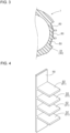
- FIGS. 4 and 5 show the busbar 50 including the surface area enlargement portion 51.
- the surface area enlargement portion 51 may have a shape that enlarges the area of the part of the busbar 50 that is exposed to the outside from the motor housing 30, specifically, have fins 52 (see FIG. 4 ) or projections and recesses 53 (see FIG. 5 ). That is, the surface area enlargement portion 51 may have a shape with at least one of the fins 52 projecting outward from the busbar 50 and the projections and recesses 53.
- the busbar 50 can be provided with the surface area enlargement portion 51 exposed from the motor housing 30, thereby increasing the cooling performance of the busbar 50.
- the corners of the fins 52 and the projections and recesses 53 are right-angled corners in side view, the corners may be rounded.
- the top of the projection and the bottom of the recess in the projections and recesses 53 may be formed into an arc shape in side view.
- the surface area enlargement portion 51 may be integrated with the busbar 50, the surface area enlargement portion 51 may be provided separately from the busbar 50. In such a case, the surface area enlargement portion 51 may be formed into a shape with the fins 52 or the projections and recesses 53 and fixed to the exposed part of the busbar 50 later as shown in FIG. 6 . In this case, the surface area enlargement portion 51 can be selected depending on the cooling performance required of the busbar 50. Thus, it is possible to prevent installation of the surface area enlargement portion 51 having an unnecessarily high cooling performance.
- FIG. 6 shows an example in which the surface area enlargement portion 51 is fastened with screw members, the surface area enlargement portion 51 may be fixed with a structure such as snap-fit or may be fixed with an adhesive material.
- the busbar 50 has been described as being provided while being exposed from the motor housing 30 at least in part.
- the busbar 50 may be provided while being exposed from the motor housing 30 in its entirety.
- the coil end 14E of the stator coil 14 or a part of the board 40 may be exposed together with the busbar 50.
- the surface area enlargement portion 51 has been described as being provided separately from the busbar 50 and fixed to the exposed part of the busbar 50.
- the surface area enlargement portion 51 may be fixed to an unexposed part of the busbar 50 and used to enlarge the surface area of the exposed part by extending the surface area enlargement portion 51.
- the present invention can be used in a pump device including an electric motor and a pump.
Landscapes
- Engineering & Computer Science (AREA)
- Power Engineering (AREA)
- Mechanical Engineering (AREA)
- General Engineering & Computer Science (AREA)
- Microelectronics & Electronic Packaging (AREA)
- Details And Applications Of Rotary Liquid Pumps (AREA)
Abstract
Description
- The present invention relates to a pump device including an electric motor and a pump.
- Hitherto, there has been used a pump device including a pump to be driven by using, as a power source, a rotational force transmitted to a rotation shaft of an electric motor. As this type of technology, there is an electric pump described in, for example,
Patent Document 1. - The electric pump described in
Patent Document 1 includes a pump unit including a suction-side oil passage communicating with a suction port and a discharge-side oil passage communicating with a discharge port, and a motor unit including a stator including a stator core and a motor case to which the stator is attached. A gap is formed between the inner peripheral surface of the motor case and the outer peripheral surface of the stator core. The gap communicates with the suction-side oil passage and the discharge-side oil passage. Thus, oil is sent from the suction-side oil passage and the discharge-side oil passage that communicate with the gap. With the oil, the heat transfer between the stator core and the motor case is improved, thereby suppressing a temperature increase of coils of the motor unit. - Patent Document 1:
Japanese Unexamined Patent Application Publication No. 2012-122451 JP 2012-122451 A - As described above, in the technology described in
Patent Document 1, the oil is sent from the suction-side oil passage and the discharge-side oil passage into the gap between the inner peripheral surface of the motor case and the outer peripheral surface of the stator core to cool the coils. With such a configuration, however, a space is required in the gap to communicate the suction-side oil passage and the discharge-side oil passage. Therefore, the size of the electric pump increases and the cost increases. Further, pump performance may decrease due to the need to distribute the oil into the gap. - Therefore, there is a demand for a pump device that can suppress a temperature increase of an electric motor with an inexpensive configuration without increasing the size and decreasing the performance.
- A characteristic configuration of a pump device according to the present invention is as follows. The pump device includes an electric motor including a motor rotor including a permanent magnet, a stator disposed on a radially outer side of the motor rotor and including a stator coil, and a rotation shaft configured to rotate integrally with the motor rotor, a pump including a pump rotor connected to one axial side of the rotation shaft, and a pump housing that houses the pump rotor, a motor housing that has a bottomed tubular shape with a side portion to which the stator is internally fixed and a bottom portion provided on the other axial side of the rotation shaft, and that houses the motor rotor in an internal space surrounded by the side portion and the bottom portion, a board on which a driver configured to drive the electric motor is mounted, and that is provided on an outer surface side of the bottom portion of the motor housing, and a busbar that electrically connects the driver and the stator coil, and that is provided while being visibly exposed to an outside at least in part when viewed from an outer side of the motor housing.
- With such a characteristic configuration, heat generated by the stator coil can be dissipated using the busbar provided between the electric motor and the driver by exposing the busbar to the outside from the motor housing. Therefore, the heat is not easily transferred from the electric motor to the driver. The busbar is made of a conductor, and the conductor has a high thermal conductivity. Therefore, the heat can easily be transferred to an exposed part of the busbar. Thus, the cooling effect of the pump device can be enhanced. Since the heat of the stator coil is not easily transferred to the driver, the cost can be reduced by changing the components of the driver to those with smaller permissible loss or by using components with smaller sizes.
- It is preferable that a surface area enlargement portion that enlarges a surface area be provided on the exposed part of the busbar.
- With such a configuration, the cooling effect of the busbar can further be enhanced. Therefore, the cost can further be reduced for the components of the driver described above.
- It is preferable that the surface area enlargement portion be provided separately from the busbar, and fixed to the exposed part of the busbar.
- With such a configuration, the surface area enlargement portion can be provided after the busbar is provided on the motor housing. Therefore, the surface area enlargement portion can be selected depending on the heat to be generated during operation after the pump device is assembled. Thus, complicated thermal design can be simplified.
- It is preferable that the surface area enlargement portion have a shape with at least one of fins projecting toward an outside from the busbar and projections and recesses.
- With such a configuration, the cooling performance of the busbar can be increased.
-
- [
FIG. 1] FIG. 1 is a sectional view of a pump device. - [
FIG. 2] FIG. 2 is a sectional view taken along a line II-II inFIG. 1 . - [
FIG. 3] FIG. 3 is a sectional view taken along a line III-III inFIG. 1 . - [
FIG. 4] FIG. 4 shows an example of a busbar including a surface area enlargement portion. - [
FIG. 5] FIG. 5 shows an example of the busbar including the surface area enlargement portion. - [
FIG. 6] FIG. 6 shows an example of attachment of the surface area enlargement portion to the busbar. - A pump device according to the present invention can perform cooling via a busbar that connects an electric motor and a driver that drives the electric motor. A
pump device 1 of the present embodiment will be described below. -
FIG. 1 is a side sectional view of thepump device 1 of the present embodiment. Thepump device 1 includes anelectric motor 10, apump 20, amotor housing 30, aboard 40, and abusbar 50. - The
electric motor 10 includes amotor rotor 11, astator 12, and arotation shaft 13. Themotor rotor 11 is formed into a cylindrical shape by stacking disc-shaped electromagnetic steel sheets. A plurality of permanent magnets PM is provided along a circumferential direction so as to pass through thecylindrical motor rotor 11 in an axial direction. Thestator 12 is disposed on a radially outer side of themotor rotor 11 and includesstator coils 14. Thestator 12 is formed by winding wires around teeth (not shown). Therotation shaft 13 is fixed to a throughhole 15 at the radial center of thecylindrical motor rotor 11 so as to rotate integrally with themotor rotor 11. - The
pump 20 includes apump rotor 21, anouter rotor 23, and apump housing 22.FIG. 2 is a sectional view taken along a line II-II inFIG. 1 . Thepump rotor 21 is connected to one axial side of therotation shaft 13. As described above, therotation shaft 13 is fixed to themotor rotor 11 so as to pass through themotor rotor 11 in the axial direction. Therotation shaft 13 is provided so as to coaxially extend on one axial side of themotor rotor 11, and thepump rotor 21 is connected and fixed to this extended part. Thepump rotor 21 is formed into an annular shape and has a plurality ofexternal teeth 21A formed on its outer peripheral surface. Theseexternal teeth 21A are formed into a tooth flank shape conforming to a trochoidal curve, a cycloidal curve, or the like. Thepump rotor 21 is disposed coaxially with the rotation axis of therotation shaft 13 and is rotatably supported on thepump housing 22 via therotation shaft 13. Thus, thepump rotor 21 rotates integrally with therotation shaft 13. - The
pump housing 22 houses thepump rotor 21 and theouter rotor 23. Theouter rotor 23 is formed into an annular shape with a plurality ofinternal teeth 23A that meshes with theexternal teeth 21A, and rotates about an axis that is eccentric to the axis of thepump rotor 21 in response to the rotation of thepump rotor 21. The number of theinternal teeth 23A of theouter rotor 23 is larger by one than the number of theexternal teeth 21A of thepump rotor 21. Theinternal teeth 23A are formed into a tooth flank shape in which theinternal teeth 23A come into contact with theexternal teeth 21A of thepump rotor 21 when theouter rotor 23 rotates. - Referring back to
FIG. 1 , thepump housing 22 is provided with acasing 24 on an open side of a housing space that houses thepump rotor 21. A suction port 25 and adischarge port 26 are formed in thecasing 24. The suction port 25 is an opening formed in awall portion 24A of thecasing 24. Oil is supplied between theexternal teeth 21A and theinternal teeth 23A from the suction port 25. - Similarly to the suction port 25, the
discharge port 26 is an opening formed in thewall portion 24A of thecasing 24. The oil supplied from the suction port 25 along with the rotation of thepump rotor 21 is discharged from thedischarge port 26 between theexternal teeth 21A and theinternal teeth 23A. - The
motor housing 30 is formed into a bottomed tubular shape with aside portion 31 and abottom portion 32. The bottomed tubular shape is a shape in which one axial end of a tubular body is covered with thebottom portion 32. This tubular body corresponds to theside portion 31. Themotor housing 30 is made of a non-magnetic and insulating material. Thestator 12 is fixed inside theside portion 31. Thestator 12 may be fixed in such a manner that themotor housing 30 is formed by resin molding and thestator 12 is sealed inside at that time. Thebottom portion 32 is provided on the other axial side of therotation shaft 13, that is, on the opposite side of therotation shaft 13 to the side on which thepump 20 is provided. Therefore, themotor housing 30 is provided such that thebottom portion 32 faces thepump rotor 21 along the axial direction of therotation shaft 13. - The
motor housing 30 houses themotor rotor 11 in an internal space S surrounded by theside portion 31 and thebottom portion 32. At this time, a clearance Q is provided between themotor rotor 11 and thestator 12 so that themotor rotor 11 can rotate relative to thestator 12. - The
pump housing 22 has arecess 71 communicating with thedischarge port 26 and arecess 81 communicating with the suction port 25 to facilitate the rotation of thepump rotor 21. -
Sealing members 91 are provided between thepump housing 22 and themotor housing 30 to secure liquid tightness of the internal space S. Although two sealingmembers 91 are provided inFIG. 1 , one sealingmember 91 may be provided. - A
driver 41 that drives theelectric motor 10 is mounted on theboard 40. Theboard 40 is provided on an outer surface side of thebottom portion 32 of the motor housing 30 (opposite side to the side on which themotor rotor 11 is provided). Thedriver 41 is, for example, an inverter that energizes the stator coils 14 to drive theelectric motor 10. The inverter includes a plurality of switchingelements 42. Therefore, the plurality of switchingelements 42 is mounted on theboard 40. Theboard 40 is covered with acover member 43 made of metal (for example, made of aluminum) with the switchingelements 42 mounted thereon. In the example ofFIG. 1 , theboard 40 is fastened to themotor housing 30 withbolts 95. - The
busbar 50 electrically connects thedriver 41 and the stator coils 14. As described above, thedriver 41 is mounted on theboard 40 provided on the outer side of thebottom portion 32 of themotor housing 30. The stator coils 14 are provided in thestator 12 internally fixed to theside portion 31. Thebusbar 50 is made of a conductor (for example, copper) that connects thedriver 41 and the stator coils 14. One end of thebusbar 50 can be connected to the end (not shown) of thestator coil 14 at acoil end 14E, and the other end can be connected to theboard 40 via thebolt 95 that fixes theboard 40 to themotor housing 30. - The plurality of switching
elements 42 is mounted on theboard 40 as described above. The switchingelements 42 generate heat when the stator coils 14 are energized. The stator coils 14 also generate heat due to a flow of current. The heat generated by the switchingelements 42 on theboard 40 can be dissipated from thecover member 43 via aheat dissipation sheet 49 made of silicon or the like between the switchingelements 42 and thecover member 43. However, the stator coils 14 are covered with themotor housing 30 and the heat cannot be dissipated by using theheat dissipation sheet 49 or the like. Therefore, as shown inFIG. 3 that is a sectional view taken along a line III-III inFIG. 1 , thebusbar 50 that connects the stator coils 14 and thedriver 41 constituted by the switchingelements 42 is provided while being exposed to the outside from themotor housing 30 at least in part. The state in which thebusbar 50 is exposed to the outside from themotor housing 30 means a state in which thebusbar 50 is visible when thepump device 1 is viewed from the outside. Thus, thebusbar 50 functions as a radiator to dissipate the heat from the switchingelements 42 and the stator coils 14 and furthermore cool them. - A surface
area enlargement portion 51 for enlarging the surface area of the exposed part may be provided at the part of thebusbar 50 that is exposed to the outside from themotor housing 30.FIGS. 4 and5 show thebusbar 50 including the surfacearea enlargement portion 51. The surfacearea enlargement portion 51 may have a shape that enlarges the area of the part of thebusbar 50 that is exposed to the outside from themotor housing 30, specifically, have fins 52 (seeFIG. 4 ) or projections and recesses 53 (seeFIG. 5 ). That is, the surfacearea enlargement portion 51 may have a shape with at least one of thefins 52 projecting outward from thebusbar 50 and the projections and recesses 53. Thus, thebusbar 50 can be provided with the surfacearea enlargement portion 51 exposed from themotor housing 30, thereby increasing the cooling performance of thebusbar 50. Although the corners of thefins 52 and the projections and recesses 53 are right-angled corners in side view, the corners may be rounded. The top of the projection and the bottom of the recess in the projections and recesses 53 may be formed into an arc shape in side view. - Although the surface
area enlargement portion 51 may be integrated with thebusbar 50, the surfacearea enlargement portion 51 may be provided separately from thebusbar 50. In such a case, the surfacearea enlargement portion 51 may be formed into a shape with thefins 52 or the projections and recesses 53 and fixed to the exposed part of thebusbar 50 later as shown inFIG. 6 . In this case, the surfacearea enlargement portion 51 can be selected depending on the cooling performance required of thebusbar 50. Thus, it is possible to prevent installation of the surfacearea enlargement portion 51 having an unnecessarily high cooling performance. AlthoughFIG. 6 shows an example in which the surfacearea enlargement portion 51 is fastened with screw members, the surfacearea enlargement portion 51 may be fixed with a structure such as snap-fit or may be fixed with an adhesive material. - In the above embodiment, the
busbar 50 has been described as being provided while being exposed from themotor housing 30 at least in part. Thebusbar 50 may be provided while being exposed from themotor housing 30 in its entirety. Thecoil end 14E of thestator coil 14 or a part of theboard 40 may be exposed together with thebusbar 50. - In the above embodiment, the surface
area enlargement portion 51 has been described as being provided separately from thebusbar 50 and fixed to the exposed part of thebusbar 50. The surfacearea enlargement portion 51 may be fixed to an unexposed part of thebusbar 50 and used to enlarge the surface area of the exposed part by extending the surfacearea enlargement portion 51. - The present invention can be used in a pump device including an electric motor and a pump.
-
- 1: pump device
- 10: electric motor
- 11: motor rotor
- 12: stator
- 13: rotation shaft
- 14: stator coil
- 20: pump
- 21: pump rotor
- 22: pump housing
- 30: motor housing
- 31: side portion
- 32: bottom portion
- 40: board
- 41: driver
- 50: busbar
- 51: surface area enlargement portion
- 52: fin
- 53: projection and recess
- PM: permanent magnet
- S: internal space
Claims (4)
- A pump device comprising:an electric motor including a motor rotor including a permanent magnet, a stator disposed on a radially outer side of the motor rotor and including a stator coil, and a rotation shaft configured to rotate integrally with the motor rotor;a pump including a pump rotor connected to one axial side of the rotation shaft, and a pump housing that houses the pump rotor;a motor housing that has a bottomed tubular shape with a side portion to which the stator is internally fixed and a bottom portion provided on the other axial side of the rotation shaft, and that houses the motor rotor in an internal space surrounded by the side portion and the bottom portion;a board on which a driver configured to drive the electric motor is mounted, and that is provided on an outer surface side of the bottom portion of the motor housing; anda busbar that electrically connects the driver and the stator coil, and that is provided while being visibly exposed to an outside at least in part when viewed from an outer side of the motor housing.
- The pump device according to claim 1, wherein
a surface area enlargement portion that enlarges a surface area is provided on an exposed part of the busbar. - The pump device according to claim 2, wherein:the surface area enlargement portion is provided separately from the busbar; andthe surface area enlargement portion is fixed to the exposed part of the busbar.
- The pump device according to claim 2, wherein
the surface area enlargement portion has a shape with at least one of fins projecting toward an outside from the busbar and projections and recesses.
Applications Claiming Priority (2)
| Application Number | Priority Date | Filing Date | Title |
|---|---|---|---|
| JP2021082216 | 2021-05-14 | ||
| PCT/JP2022/013124 WO2022239484A1 (en) | 2021-05-14 | 2022-03-22 | Pump device |
Publications (2)
| Publication Number | Publication Date |
|---|---|
| EP4339460A1 true EP4339460A1 (en) | 2024-03-20 |
| EP4339460A4 EP4339460A4 (en) | 2024-04-17 |
Family
ID=84028206
Family Applications (1)
| Application Number | Title | Priority Date | Filing Date |
|---|---|---|---|
| EP22807189.0A Withdrawn EP4339460A4 (en) | 2021-05-14 | 2022-03-22 | PUMPING DEVICE |
Country Status (5)
| Country | Link |
|---|---|
| US (1) | US20240151226A1 (en) |
| EP (1) | EP4339460A4 (en) |
| JP (1) | JPWO2022239484A1 (en) |
| CN (1) | CN117321308A (en) |
| WO (1) | WO2022239484A1 (en) |
Cited By (1)
| Publication number | Priority date | Publication date | Assignee | Title |
|---|---|---|---|---|
| US12674453B2 (en) | 2022-12-19 | 2026-07-07 | Sumitomo Electric Sintered Alloy, Ltd. | Pump assembly |
Families Citing this family (2)
| Publication number | Priority date | Publication date | Assignee | Title |
|---|---|---|---|---|
| DE102022133528A1 (en) | 2022-12-15 | 2024-06-20 | Valeo Powertrain Gmbh | Liquid pump |
| US12352203B2 (en) * | 2022-12-22 | 2025-07-08 | Garrett Transportation I Inc. | Turbomachine with e-machine controller having cooled bus bar member |
Family Cites Families (42)
| Publication number | Priority date | Publication date | Assignee | Title |
|---|---|---|---|---|
| DE2838966A1 (en) * | 1978-09-07 | 1980-03-20 | Bosch Gmbh Robert | HOLDING AND STORAGE DEVICE FOR COMPONENTS IN ELECTRICAL MACHINES, ESPECIALLY FOR THREE-PHASE GENERATOR |
| JP3346039B2 (en) * | 1994-08-08 | 2002-11-18 | トヨタ自動車株式会社 | Inverter integrated motor |
| DE19704226B4 (en) * | 1997-02-05 | 2004-09-30 | Sew-Eurodrive Gmbh & Co. Kg | Klemmdeckelumrichter |
| JP2000255252A (en) * | 1999-03-11 | 2000-09-19 | Matsushita Electric Ind Co Ltd | Automotive air conditioners |
| DE10009587A1 (en) * | 2000-02-29 | 2001-08-30 | Mannesmann Rexroth Ag | Compact electrohydraulic motor pump unit |
| US6721181B1 (en) * | 2002-09-27 | 2004-04-13 | Rockwell Automation Technologies, Inc. | Elongated heat sink for use in converter assemblies |
| US6822850B2 (en) * | 2002-09-27 | 2004-11-23 | Rockwell Automation Technologies, Inc. | Laminated bus bar for use with a power conversion configuration |
| JP4427373B2 (en) * | 2004-03-31 | 2010-03-03 | 三菱重工業株式会社 | Electric compressor |
| DE102007034327A1 (en) * | 2007-07-24 | 2009-01-29 | Robert Bosch Gmbh | Electric motor, in particular actuating or drive motor in motor vehicles |
| US7872385B2 (en) * | 2007-07-27 | 2011-01-18 | GM Global Technology Operations LLC | Electric motor power connection assembly |
| JP4754009B2 (en) * | 2009-06-04 | 2011-08-24 | 三菱電機株式会社 | Rotating electric machine for vehicles |
| JP4851575B2 (en) * | 2009-11-02 | 2012-01-11 | 三菱電機株式会社 | Controller-integrated rotating electrical machine |
| US8362665B2 (en) * | 2009-11-11 | 2013-01-29 | Remy Technologies, L.L.C. | Liquid cooled stator terminal block for an electric machine |
| JP2012122451A (en) * | 2010-12-10 | 2012-06-28 | Yamada Seisakusho Co Ltd | Electric pump |
| CN103155369B (en) * | 2010-12-13 | 2015-03-04 | 三菱电机株式会社 | Controller-integrated electric rotating machine |
| JP5534353B2 (en) * | 2011-03-31 | 2014-06-25 | アイシン・エィ・ダブリュ株式会社 | Inverter device |
| JP5534352B2 (en) * | 2011-03-31 | 2014-06-25 | アイシン・エィ・ダブリュ株式会社 | Inverter device |
| JP2012223030A (en) * | 2011-04-13 | 2012-11-12 | Jtekt Corp | Electric motor and stator |
| KR101748639B1 (en) * | 2013-05-21 | 2017-06-19 | 히다치 오토모티브 시스템즈 가부시키가이샤 | Power conversion apparatus |
| FR3010588B1 (en) * | 2013-09-09 | 2015-10-09 | Valeo Equip Electr Moteur | PROTECTIVE COVER FOR ROTATING ELECTRIC MACHINE FOR MOTOR VEHICLE |
| FR3010590B1 (en) * | 2013-09-09 | 2015-10-09 | Valeo Equip Electr Moteur | ELECTRONIC ASSEMBLY FOR ROTATING ELECTRIC MACHINE FOR MOTOR VEHICLE |
| US20170016442A1 (en) * | 2014-03-14 | 2017-01-19 | Aisin Seiki Kabushiki Kaisha | Mounting structure for electric oil pump |
| JP2016008526A (en) * | 2014-06-23 | 2016-01-18 | アイシン精機株式会社 | Electric pump |
| JP6552166B2 (en) * | 2014-07-15 | 2019-07-31 | 日本電産トーソク株式会社 | Motor for electric oil pump |
| JP6286320B2 (en) * | 2014-08-07 | 2018-02-28 | 日立オートモティブシステムズ株式会社 | Power module |
| JP6540986B2 (en) * | 2015-01-26 | 2019-07-10 | 株式会社デンソー | Electric rotating machine |
| JP6597091B2 (en) * | 2015-09-11 | 2019-10-30 | アイシン精機株式会社 | Electric pump and manufacturing method thereof |
| JP6669251B2 (en) * | 2016-04-28 | 2020-03-18 | 日産自動車株式会社 | Automotive power converter |
| DE102017111765A1 (en) * | 2016-05-31 | 2017-11-30 | Denso Corporation | Rotating electrical machine with integrated control |
| KR102359705B1 (en) * | 2016-07-20 | 2022-02-08 | 엘지마그나 이파워트레인 주식회사 | Case for electric motor |
| JP2018026483A (en) * | 2016-08-11 | 2018-02-15 | 株式会社デンソー | Semiconductor module and semiconductor device |
| JP7259223B6 (en) * | 2017-07-31 | 2023-05-10 | ニデックパワートレインシステムズ株式会社 | electric oil pump |
| WO2019044521A1 (en) * | 2017-08-31 | 2019-03-07 | 日本電産トーソク株式会社 | Circuit board assembly and electric oil pump provided with same |
| US20200208631A1 (en) * | 2017-08-31 | 2020-07-02 | Nidec Tosok Corporation | Electric oil pump |
| JP7155518B2 (en) * | 2017-12-21 | 2022-10-19 | 日本電産トーソク株式会社 | electric oil pump |
| JP7039990B2 (en) * | 2017-12-21 | 2022-03-23 | 日本電産トーソク株式会社 | Electric oil pump |
| CN112385123B (en) * | 2018-07-17 | 2024-06-28 | 三菱电机株式会社 | Rotating electric machines |
| JP2020056336A (en) * | 2018-09-28 | 2020-04-09 | 日本電産トーソク株式会社 | Electric pump device |
| JP6997740B2 (en) * | 2019-05-28 | 2022-01-18 | Kyb株式会社 | Rotating machine and manufacturing method of rotating machine |
| DE102019210308A1 (en) * | 2019-07-11 | 2021-01-14 | Robert Bosch Gmbh | Electric machine with cooled busbars |
| JP6801756B2 (en) * | 2019-09-12 | 2020-12-16 | 日本電産トーソク株式会社 | Pump device |
| US11649822B2 (en) * | 2021-02-08 | 2023-05-16 | Schaeffler Technologies AG & Co. KG | Split power gerotor pump |
-
2022
- 2022-03-22 US US18/549,243 patent/US20240151226A1/en not_active Abandoned
- 2022-03-22 CN CN202280033737.6A patent/CN117321308A/en active Pending
- 2022-03-22 WO PCT/JP2022/013124 patent/WO2022239484A1/en not_active Ceased
- 2022-03-22 JP JP2023520878A patent/JPWO2022239484A1/ja active Pending
- 2022-03-22 EP EP22807189.0A patent/EP4339460A4/en not_active Withdrawn
Cited By (1)
| Publication number | Priority date | Publication date | Assignee | Title |
|---|---|---|---|---|
| US12674453B2 (en) | 2022-12-19 | 2026-07-07 | Sumitomo Electric Sintered Alloy, Ltd. | Pump assembly |
Also Published As
| Publication number | Publication date |
|---|---|
| CN117321308A (en) | 2023-12-29 |
| WO2022239484A1 (en) | 2022-11-17 |
| JPWO2022239484A1 (en) | 2022-11-17 |
| EP4339460A4 (en) | 2024-04-17 |
| US20240151226A1 (en) | 2024-05-09 |
Similar Documents
| Publication | Publication Date | Title |
|---|---|---|
| US20240151226A1 (en) | Pump device | |
| CN103814515B (en) | Mechatronic components | |
| JP5927870B2 (en) | Electric pump | |
| JP5987331B2 (en) | Electric oil pump device | |
| JP5903089B2 (en) | Electric pump | |
| US20190195349A1 (en) | Electric Oil Pump | |
| WO2017141877A1 (en) | Electric device and electric supercharger | |
| WO2018159471A1 (en) | Pump device | |
| JP2013115860A (en) | Electric motor and electric unit including the same | |
| JP6236301B2 (en) | Electric pump | |
| JP2012223030A (en) | Electric motor and stator | |
| JP2013172564A (en) | Mechano-electric integrated module | |
| CN110836179A (en) | Mounting structure of electric pump | |
| JP7400436B2 (en) | motor and electric pump | |
| JP6047023B2 (en) | Electric pump | |
| US12448972B2 (en) | Electric oil pump | |
| JP5156223B2 (en) | Rotating electric machine | |
| JP2009100628A (en) | Electrically driven pump | |
| CN112955660A (en) | Stuffing box pump comprising a ring capacitor | |
| WO2018159472A1 (en) | Pump device | |
| JP6654414B2 (en) | Electric compressor | |
| JP5915082B2 (en) | Electric oil pump device | |
| KR20250121236A (en) | pump assembly | |
| JP2014168333A (en) | Inverter built-in rotary electric machine | |
| CN110024270A (en) | Motor with liquid refrigerating function |
Legal Events
| Date | Code | Title | Description |
|---|---|---|---|
| STAA | Information on the status of an ep patent application or granted ep patent |
Free format text: STATUS: THE INTERNATIONAL PUBLICATION HAS BEEN MADE |
|
| PUAI | Public reference made under article 153(3) epc to a published international application that has entered the european phase |
Free format text: ORIGINAL CODE: 0009012 |
|
| STAA | Information on the status of an ep patent application or granted ep patent |
Free format text: STATUS: REQUEST FOR EXAMINATION WAS MADE |
|
| REG | Reference to a national code |
Ref country code: DE Ref legal event code: R079 Free format text: PREVIOUS MAIN CLASS: F04C0015000000 Ipc: H02K0009220000 |
|
| 17P | Request for examination filed |
Effective date: 20231004 |
|
| AK | Designated contracting states |
Kind code of ref document: A1 Designated state(s): AL AT BE BG CH CY CZ DE DK EE ES FI FR GB GR HR HU IE IS IT LI LT LU LV MC MK MT NL NO PL PT RO RS SE SI SK SM TR |
|
| A4 | Supplementary search report drawn up and despatched |
Effective date: 20240315 |
|
| RIC1 | Information provided on ipc code assigned before grant |
Ipc: F04D 13/06 20060101ALI20240311BHEP Ipc: F04C 15/00 20060101ALI20240311BHEP Ipc: H02K 11/33 20160101ALI20240311BHEP Ipc: H02K 3/52 20060101ALI20240311BHEP Ipc: H02K 9/22 20060101AFI20240311BHEP |
|
| DAV | Request for validation of the european patent (deleted) | ||
| DAX | Request for extension of the european patent (deleted) | ||
| STAA | Information on the status of an ep patent application or granted ep patent |
Free format text: STATUS: THE APPLICATION IS DEEMED TO BE WITHDRAWN |
|
| 18D | Application deemed to be withdrawn |
Effective date: 20251001 |