EP4339036A1 - Véhicule automobile avec agencement de pare-chocs - Google Patents
Véhicule automobile avec agencement de pare-chocs Download PDFInfo
- Publication number
- EP4339036A1 EP4339036A1 EP23192056.2A EP23192056A EP4339036A1 EP 4339036 A1 EP4339036 A1 EP 4339036A1 EP 23192056 A EP23192056 A EP 23192056A EP 4339036 A1 EP4339036 A1 EP 4339036A1
- Authority
- EP
- European Patent Office
- Prior art keywords
- motor vehicle
- bumper
- cross member
- vehicle according
- crash boxes
- Prior art date
- Legal status (The legal status is an assumption and is not a legal conclusion. Google has not performed a legal analysis and makes no representation as to the accuracy of the status listed.)
- Granted
Links
Images

Classifications
-
- B—PERFORMING OPERATIONS; TRANSPORTING
- B60—VEHICLES IN GENERAL
- B60R—VEHICLES, VEHICLE FITTINGS, OR VEHICLE PARTS, NOT OTHERWISE PROVIDED FOR
- B60R19/00—Wheel guards; Radiator guards, e.g. grilles; Obstruction removers; Fittings damping bouncing force in collisions
- B60R19/02—Bumpers, i.e. impact receiving or absorbing members for protecting vehicles or fending off blows from other vehicles or objects
- B60R19/24—Arrangements for mounting bumpers on vehicles
- B60R19/26—Arrangements for mounting bumpers on vehicles comprising yieldable mounting means
- B60R19/34—Arrangements for mounting bumpers on vehicles comprising yieldable mounting means destroyed upon impact, e.g. one-shot type
-
- B—PERFORMING OPERATIONS; TRANSPORTING
- B60—VEHICLES IN GENERAL
- B60R—VEHICLES, VEHICLE FITTINGS, OR VEHICLE PARTS, NOT OTHERWISE PROVIDED FOR
- B60R19/00—Wheel guards; Radiator guards, e.g. grilles; Obstruction removers; Fittings damping bouncing force in collisions
- B60R19/02—Bumpers, i.e. impact receiving or absorbing members for protecting vehicles or fending off blows from other vehicles or objects
- B60R19/023—Details
-
- B—PERFORMING OPERATIONS; TRANSPORTING
- B60—VEHICLES IN GENERAL
- B60R—VEHICLES, VEHICLE FITTINGS, OR VEHICLE PARTS, NOT OTHERWISE PROVIDED FOR
- B60R19/00—Wheel guards; Radiator guards, e.g. grilles; Obstruction removers; Fittings damping bouncing force in collisions
- B60R19/02—Bumpers, i.e. impact receiving or absorbing members for protecting vehicles or fending off blows from other vehicles or objects
- B60R19/04—Bumpers, i.e. impact receiving or absorbing members for protecting vehicles or fending off blows from other vehicles or objects formed from more than one section in a side-by-side arrangement
- B60R19/12—Bumpers, i.e. impact receiving or absorbing members for protecting vehicles or fending off blows from other vehicles or objects formed from more than one section in a side-by-side arrangement vertically spaced
-
- B—PERFORMING OPERATIONS; TRANSPORTING
- B60—VEHICLES IN GENERAL
- B60R—VEHICLES, VEHICLE FITTINGS, OR VEHICLE PARTS, NOT OTHERWISE PROVIDED FOR
- B60R19/00—Wheel guards; Radiator guards, e.g. grilles; Obstruction removers; Fittings damping bouncing force in collisions
- B60R19/02—Bumpers, i.e. impact receiving or absorbing members for protecting vehicles or fending off blows from other vehicles or objects
- B60R19/24—Arrangements for mounting bumpers on vehicles
- B60R2019/247—Fastening of bumpers' side ends
Definitions
- the invention relates to a motor vehicle with at least one bumper arrangement, wherein a first bumper arrangement has a first bumper cross member and at least two spaced-apart first crash boxes, each of which is fastened with a first end to one of the two regions of the bumper cross member near the end and each with a second end Parts of the vehicle structure are attached.
- bumper arrangement which usually consists of a bumper cross member and two crash boxes that are arranged between the bumper cross member and the vehicle structure.
- the bumper arrangement in particular the crash boxes, absorb or absorb part of the energy acting on the vehicle in the event of an impact, so that damage to the vehicle structure or to the vehicle occupants resulting from the impact can be reduced or even prevented.
- Different crash boxes are known. For example, these can be made from one-piece or multi-piece hollow profile sections.
- several sheet metal parts are connected to one another to form a hollow profile section, which can preferably be done by welding two half-shells made of sheet metal.
- the hollow profile sections have open ends on the front side, with a first end being welded or screwed to the bumper cross member or to a holder arranged on the bumper cross member and the opposite second end or a plate welded to the second end being welded to or attached to the vehicle structure, for example a side member is screwed to this.
- the known crash boxes have a relatively high dead weight due to their closed profile shape and the possibly multi-part design. Moisture or dirt can enter the interior of the self-contained hollow profiles, for example through gaps, and lead to corrosion. To avoid corrosion, the cavity of the crash boxes can be coated with a corrosion protection layer, such as a paint. So that excess paint can drip off after application, appropriate drip holes must be made in the walls of the crash boxes. If a crash box is made up of several parts, the parts must be connected to one another, for example by welding the parts together, which is complex and may introduce undesirable weak points into the material.
- the object of the invention is to create a vehicle with an improved bumper arrangement, which has a low weight and which can be produced easily and inexpensively.
- the components of the bumper assembly should be deformed in the event of an impact in such a way that particularly little damage is caused to the vehicle structure and to the vehicle occupants.
- targeted deformation of the bumper arrangement should also improve pedestrian protection, i.e. reduce injuries to pedestrians in the event of a collision with the vehicle.
- each crash box consist of a trough-like profile section with a trough base and two legs projecting transversely therefrom, each profile section having a transversely projecting, molded tab folded over from the trough base at least at the front first end, with which the Crash box is attached to the bumper cross member.
- the crash box has a one-piece channel shape in the manner of an open hollow profile, so that there is no need for complicated connection of several parts by welding such parts and the crash box has a particularly low weight. If the crash box is coated, for example, with an anti-corrosion paint, excess paint can easily drip out of the cavity that is open on one side without drain openings or holes having to be made in one of the walls.
- the molded tab enables a particularly simple and cost-effective connection of the crash box to the bumper cross member, since additional components for connecting the crash box to the bumper cross member can be dispensed with.
- additional components for connecting the crash box to the bumper cross member can be dispensed with.
- the profile sections that are open on one side can be integrated into the bumper arrangement in such a way that their gutter opening opposite the gutter base is preferably directed downwards, in the direction of the contact plane of the vehicle.
- the tab formed on the bottom of the channel which extends at least to the alignment line of the legs or beyond, is pressed against the end faces of the legs, so that the legs and with them the entire profile section are pressed and deformed in the longitudinal direction of the vehicle towards the vehicle. Since the crash boxes have lower resistance in the area of the gutter opening due to the lack of wall surface in this area, the crash box is more easily deformed in this area.
- the crash box is essentially compressed in the longitudinal direction of the vehicle (x-axis). Rotation of the crash box about the vehicle's transverse axis (y-axis) is preferably completely prevented, so that the crash boxes are prevented from simply bending and optimal energy absorption can occur.
- the bumper cross member attached to the crash boxes follows this movement.
- the orientation of the gutter opening therefore has a significant effect on the direction of deformation of the crash boxes and the bumper cross member, whereby the Alignment can be done in any other direction in order to adapt the bumper arrangement to a corresponding area of application.
- each profile section has a transversely projecting, molded tab at the front end, which is folded over from the bottom of the channel and with which the crash box is fastened to the vehicle structure.
- the crash box can be easily attached to the vehicle structure, preferably screwed or welded. There is no need for additional components with which the crash box has to be attached to the vehicle structure.
- the longitudinal extent of the profile sections is directed parallel to the vehicle's longitudinal axis (x-axis), with the gutter opening formed by the legs and the gutter base being directed transversely thereto, preferably towards the contact plane of the motor vehicle.
- the channel opening is therefore preferably aligned parallel to the y-axis or z-axis of the vehicle, with an alignment particularly preferably parallel to the z-axis, namely in the direction of the contact surface of the vehicle, so that there is neither liquid nor dirt in the open hollow profile section can accumulate and the risk of corrosion is reduced or prevented.
- the channel-like profile sections have a substantially U-shaped or W-shaped cross section.
- first crash boxes are connected to the first cross member and/or to the parts of the vehicle structure in a material-locking or non-positive manner.
- connection is preferably made by welding or screwing.
- crash boxes including the tabs, are each one-piece sheet metal parts made of aluminum or steel.
- a fastening element for the crash box is integrated into the crash box on the bumper cross member and possibly also on the vehicle structure, so that additional holders on the cross member and, if necessary, fasteners for fastening the crash box to the vehicle structure are no longer necessary.
- the profile sections preferably have beads in the bottom of the gutter as a deformation aid.
- edge edges of the leg surfaces have a deformation trimming as a deformation aid.
- the first bumper arrangement is arranged in the area of a lower load level, which is formed parallel to the contact plane (xy plane) of the motor vehicle, with a second bumper arrangement being provided in the area of an upper load level, which is parallel to the lower load level and to the contact level is designed, wherein the upper load level has a greater distance from the contact level than the lower load level, the second bumper arrangement having a second bumper cross member and two further spaced apart second crash boxes, one end of which is attached to one of the two near-end regions of the second bumper cross member and the further end of which is attached to parts of the vehicle structure.
- the first crash boxes of the bumper arrangement of the lower load level are preferably aligned with their gutter opening downwards, towards the contact plane of the vehicle.
- the first crash boxes are preferably compressed in the longitudinal direction of the vehicle (x-axis) before the second crash boxes are deformed.
- a movement of the crash boxes around the vehicle's transverse axis (y-axis) preferably does not occur or only occurs slightly, so that the crash boxes are prevented from bending and optimal energy absorption can occur.
- the first bumper cross member attached to the first crash boxes follows this movement.
- the upper load level bumper assembly may have a structure known in the art.
- the second bumper arrangement can also be designed in the manner of the first bumper arrangement.
- the second bumper arrangement then also has the advantages mentioned for the first bumper arrangement. In the event of an impact, the second crash boxes are only deformed when the first crash boxes have already been compressed to a certain extent in the longitudinal direction of the vehicle. This subsequent deformation of the second crash boxes in particular improves pedestrian protection.
- first crash boxes have a lower rigidity than the second crash boxes.
- the bumper arrangement is first deformed in the area of the lower load level, before deformation occurs in the area of the upper load level.
- first bumper cross member and the second bumper cross member are connected to one another by connecting elements which are preferably arranged on the areas near the ends of both bumper cross members, since this means that the first bumper cross member is held at a distance from the second bumper cross member and only one a certain rotational movement of the first bumper cross member around the y-axis is enabled and the first crash boxes and the bumper cross member are prevented from simply bending downwards.
- each tab at least covers the end faces of the legs or protrudes laterally over the surfaces of the legs, so that the tabs press against the legs of the crash boxes when force is applied during impact and these are deformed towards the vehicle.
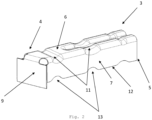
- the figures show a first bumper arrangement 1 for a motor vehicle, for a lower load level, which is designed parallel to the contact plane (xy plane) of the motor vehicle.
- the vehicle axles are in Fig. 1 shown.
- the first bumper arrangement 1 has a first bumper cross member 2 and two spaced-apart first crash boxes 3, each of which is attached with a first end 4 to one of the two near-end regions of the bumper cross member 2 and each of which is attached to parts of the vehicle structure with a second end 5 .
- the first ends 4 of the Crash boxes 3 are cohesively connected to the first cross member 2.
- the second ends 5 of the crash boxes 3 can be screwed to a plate 20 on parts of the vehicle structure.
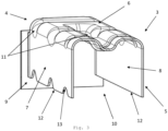
- the first crash boxes 3 each consist of a trough-like profile section with a trough base 6 and two legs 7, 8 projecting transversely therefrom, each profile section having a transversely projecting, molded tab 9 at the frontal first end 4, which is folded over by approximately 90 ° from the trough base 6, as it in Fig. 2 is shown.
- the crash box 3 is welded to the bumper cross member 2 with the tab 9 ( Fig. 1 ).
- the longitudinal extent of the profile sections is directed parallel to the vehicle's longitudinal axis (x-axis), with the gutter opening 10 formed by the legs 7, 8 and the gutter base 6 being directed transversely thereto, parallel to the z-axis of the vehicle, towards the contact plane of the motor vehicle ( Fig. 1 ), so that neither liquid nor dirt can accumulate in the open hollow profile section and corrosion can be reduced or even prevented.
- a second bumper arrangement 14 is arranged in the area of an upper load level, which is formed parallel to the lower load level and to the contact level, the upper load level being at a greater distance from the contact level than the lower load level, the second bumper arrangement 14 having a second bumper cross member 15 and two further spaced apart second crash boxes 16, one end 17 of which is attached to one of the two near-end regions of the second bumper cross member 15 and whose another end 18 is attached to parts of the vehicle structure.
- the bumper arrangements 2, 14 shown in this exemplary embodiment are designed in such a way that the first crash boxes arranged in the lower load level are first compressed in the event of an impact in the longitudinal direction of the vehicle (x-axis) before the second crash boxes are deformed.
- a rotation of the first crash boxes around the vehicle transverse axis and a mere bending of the crash boxes in the event of a load is almost completely prevented, in particular by the channel shape and the tab formed onto the channel base.
- the bumper cross member attached to the crash boxes follows this movement.
- the subsequent deformation of the crash boxes has a beneficial effect on pedestrian protection, for example.
- An alternative design can be made to meet other criteria.
- the first crash boxes 3 with their openings 10 arranged opposite the gutter base 6 are aligned downwards towards the contact plane of the vehicle.
- the flap 9 of the first crash boxes 3, which is folded over by the gutter base 6, projects laterally over the surfaces of the legs 7, 8, which Fig. 3 shows.
- the tab 9 is pressed at the front against the profile section, in particular against the legs 7, 8 of the crash boxes 3, so that they are deformed by the acting force and deformed in the direction of the vehicle.
- the respective channel opening 10 is directed towards the contact plane and which is on the Tabs 9 formed on the bottom of the gutter support the compression of the crash boxes in the longitudinal direction of the vehicle (x-axis) in the event of an impact and control the rotation of the crash box 3 about the y-axis of the vehicle.
- first crash boxes 3 have a lower rigidity compared to the second crash boxes 16, so that in the event of an impact, the first bumper arrangement 1 is first deformed in the area of the lower load level before a deformation then takes place in the area of the upper load level.
- first bumper cross member 2 and the second bumper cross member 15 are connected to one another by connecting elements 19. These are each arranged on both end-near areas of the bumper cross member 2, 15 and keep the first bumper cross member 2 at a distance from the second bumper cross member 15, so that in the event of an impact, the rotation of the first bumper cross member 2 about the y-axis of the vehicle is also supported and a mere The first crash boxes 3 are prevented from bending downwards.
- the profile sections have a partly U-shaped and partly W-shaped cross section, the W-shaped section being formed by a bead 11 in the gutter base 6. Due to this shape, the profile sections have a good Stiffness with low weight and can be produced cost-effectively.
- crash boxes 3 including the tabs 9 are molded sheet metal parts made of aluminum or steel, the tabs 9 being molded onto the gutter base 6, so that the crash box 3 can be connected to the bumper cross member 2 in a particularly simple and cost-effective manner.
- the profile sections in the gutter base 6 have beads 11 as a deformation aid.
- edge edges 12 of the legs 7, 8 have a deformation trim 13 as a deformation aid.
- the invention is not limited to the exemplary embodiment, but is variable in many ways within the scope of the disclosure.
Landscapes
- Engineering & Computer Science (AREA)
- Mechanical Engineering (AREA)
- Vibration Dampers (AREA)
- Body Structure For Vehicles (AREA)
Applications Claiming Priority (1)
| Application Number | Priority Date | Filing Date | Title |
|---|---|---|---|
| DE102022123604.8A DE102022123604A1 (de) | 2022-09-15 | 2022-09-15 | Kraftfahrzeug mit Stoßfängeranordnung |
Publications (2)
| Publication Number | Publication Date |
|---|---|
| EP4339036A1 true EP4339036A1 (fr) | 2024-03-20 |
| EP4339036B1 EP4339036B1 (fr) | 2025-10-22 |
Family
ID=87748028
Family Applications (1)
| Application Number | Title | Priority Date | Filing Date |
|---|---|---|---|
| EP23192056.2A Active EP4339036B1 (fr) | 2022-09-15 | 2023-08-18 | Véhicule automobile avec agencement de pare-chocs |
Country Status (5)
| Country | Link |
|---|---|
| US (1) | US12539821B2 (fr) |
| EP (1) | EP4339036B1 (fr) |
| CN (1) | CN117698625A (fr) |
| DE (1) | DE102022123604A1 (fr) |
| ES (1) | ES3059838T3 (fr) |
Families Citing this family (2)
| Publication number | Priority date | Publication date | Assignee | Title |
|---|---|---|---|---|
| DE102022123604A1 (de) * | 2022-09-15 | 2024-03-21 | GEDIA Gebrüder Dingerkus GmbH | Kraftfahrzeug mit Stoßfängeranordnung |
| USD1043482S1 (en) * | 2023-04-26 | 2024-09-24 | Honda Motor Co., Ltd. | Rear bumper for automobile |
Citations (4)
| Publication number | Priority date | Publication date | Assignee | Title |
|---|---|---|---|---|
| JP4685819B2 (ja) * | 2007-03-12 | 2011-05-18 | トヨタ自動車株式会社 | バンパリインフォースメント支持構造 |
| US20180370470A1 (en) * | 2015-12-21 | 2018-12-27 | Gestamp Hardtech Ab | Bumper |
| JP2019104464A (ja) * | 2017-12-14 | 2019-06-27 | マツダ株式会社 | 車両の衝撃吸収構造 |
| US20200384934A1 (en) * | 2018-02-28 | 2020-12-10 | Mazda Motor Corporation | Shock absorbing structure for vehicle |
Family Cites Families (25)
| Publication number | Priority date | Publication date | Assignee | Title |
|---|---|---|---|---|
| JPH05162594A (ja) | 1991-12-17 | 1993-06-29 | Suzuki Motor Corp | 自動車のバンパ構造 |
| JP3110654B2 (ja) * | 1995-06-20 | 2000-11-20 | 本田技研工業株式会社 | 車両用バンパ取付構造 |
| JP3531767B2 (ja) * | 1995-07-14 | 2004-05-31 | 本田技研工業株式会社 | 車両用バンパ取付構造 |
| DE19959701A1 (de) * | 1999-12-10 | 2001-06-21 | Daimler Chrysler Ag | Vorrichtung zur Stoßenergieaufnahme bei Kraftfahrzeugen |
| DE10154113A1 (de) | 2001-11-03 | 2003-05-15 | Opel Adam Ag | Frontstruktur eines Kraftfahrzeuges |
| US6918621B2 (en) * | 2003-11-12 | 2005-07-19 | Alcoa Inc. | Bumper system for a motor vehicle |
| DE102004014047B4 (de) * | 2004-03-19 | 2006-01-05 | Benteler Automobiltechnik Gmbh | Anbindung einer Crashbox an den Querträger |
| FR2887211B1 (fr) * | 2005-06-20 | 2007-09-07 | Vallourec Vitry | Voie basse guidee pour avant de vehicule automobile |
| SE0701298L (sv) * | 2007-05-30 | 2008-11-18 | Gestamp Hardtech Ab | Stötfångarbalk |
| JP5211133B2 (ja) * | 2010-10-08 | 2013-06-12 | 本田技研工業株式会社 | 車体前部構造 |
| EP2719582B1 (fr) * | 2011-06-10 | 2016-04-20 | UACJ Corporation | Dispositif d'amortisseur et pare-chocs |
| JP6004089B2 (ja) * | 2013-04-04 | 2016-10-05 | トヨタ自動車株式会社 | 車体端部構造 |
| US8991901B2 (en) * | 2013-05-07 | 2015-03-31 | GM Global Technology Operations LLC | Energy absorber device for a vehicle and method of manufacturing same |
| JP2015168364A (ja) * | 2014-03-07 | 2015-09-28 | トヨタ自動車株式会社 | 車体の前部構造体 |
| EP2949518B1 (fr) * | 2014-05-27 | 2017-06-14 | Fiat Group Automobiles S.p.A. | Structure avant de véhicule à moteur avec une unité frontale améliorée |
| KR20160060271A (ko) * | 2014-11-20 | 2016-05-30 | 현대자동차주식회사 | 차량의 크래쉬박스 및 그 조립방법 |
| WO2017086205A1 (fr) * | 2015-11-20 | 2017-05-26 | マツダ株式会社 | Structure d'élément d'absorption de choc pour véhicule |
| US9902349B2 (en) * | 2016-03-22 | 2018-02-27 | Ford Global Technologies, Llc | Vehicle bumper assembly |
| KR101836709B1 (ko) * | 2016-10-04 | 2018-03-09 | 현대자동차주식회사 | 차량용 크래쉬 박스 |
| JP6323533B2 (ja) * | 2016-10-28 | 2018-05-16 | マツダ株式会社 | 車両の衝撃吸収構造 |
| JP2018100055A (ja) * | 2016-12-21 | 2018-06-28 | トヨタ自動車株式会社 | エネルギ吸収構造 |
| JP6562064B2 (ja) * | 2017-12-14 | 2019-08-28 | マツダ株式会社 | 車両の衝撃吸収構造 |
| DE102021102365B4 (de) * | 2021-02-02 | 2023-03-09 | Benteler Automobiltechnik Gmbh | Stoßfängeranordnung mit zusätzlicher Abstützung |
| JP7419327B2 (ja) * | 2021-12-03 | 2024-01-22 | 豊田鉄工株式会社 | クラッシュボックス |
| DE102022123604A1 (de) * | 2022-09-15 | 2024-03-21 | GEDIA Gebrüder Dingerkus GmbH | Kraftfahrzeug mit Stoßfängeranordnung |
-
2022
- 2022-09-15 DE DE102022123604.8A patent/DE102022123604A1/de active Pending
-
2023
- 2023-07-21 US US18/224,672 patent/US12539821B2/en active Active
- 2023-08-18 ES ES23192056T patent/ES3059838T3/es active Active
- 2023-08-18 EP EP23192056.2A patent/EP4339036B1/fr active Active
- 2023-09-15 CN CN202311197927.4A patent/CN117698625A/zh active Pending
Patent Citations (4)
| Publication number | Priority date | Publication date | Assignee | Title |
|---|---|---|---|---|
| JP4685819B2 (ja) * | 2007-03-12 | 2011-05-18 | トヨタ自動車株式会社 | バンパリインフォースメント支持構造 |
| US20180370470A1 (en) * | 2015-12-21 | 2018-12-27 | Gestamp Hardtech Ab | Bumper |
| JP2019104464A (ja) * | 2017-12-14 | 2019-06-27 | マツダ株式会社 | 車両の衝撃吸収構造 |
| US20200384934A1 (en) * | 2018-02-28 | 2020-12-10 | Mazda Motor Corporation | Shock absorbing structure for vehicle |
Also Published As
| Publication number | Publication date |
|---|---|
| CN117698625A (zh) | 2024-03-15 |
| US12539821B2 (en) | 2026-02-03 |
| US20240092295A1 (en) | 2024-03-21 |
| ES3059838T3 (en) | 2026-03-24 |
| EP4339036B1 (fr) | 2025-10-22 |
| DE102022123604A1 (de) | 2024-03-21 |
Similar Documents
| Publication | Publication Date | Title |
|---|---|---|
| DE19756334C2 (de) | Energieabsorbierendes Deformationsprofil für ein Kraftfahrzeug | |
| EP0798197A1 (fr) | Partie modulaire avant de véhicule | |
| DE102016212297B4 (de) | Kraftfahrzeug | |
| DE3125687A1 (de) | "stossfaenger fuer kraftfahrzeuge" | |
| DE2628104A1 (de) | Fahrzeugkarosserie | |
| EP4339036B1 (fr) | Véhicule automobile avec agencement de pare-chocs | |
| DE10126195C1 (de) | Fronthaubenanordnung für einen Personenkraftwagen | |
| DE102015203309B4 (de) | Fahrzeug-Karosseriestruktur | |
| EP1716020A2 (fr) | Carrosserie de vehicule | |
| WO2007059954A1 (fr) | Support de montage de structure hybride | |
| EP1840002A1 (fr) | Elément déformable pour absorber les chocs latéraux dans la zone latérale d'un véhicule | |
| EP1923257B1 (fr) | Fixation pour un siège de véhicule automobile | |
| DE102020104097A1 (de) | Kraftfahrzeug-Stoßfänger | |
| DE19853338B4 (de) | Anordnung mit einer Frontsäule für einen Karosserierahmen eines Kraftfahrzeugs | |
| DE112006001913T5 (de) | Kollisionsschutzsystem | |
| EP1116641B1 (fr) | Structure avant de véhicule automobile | |
| EP1600338B1 (fr) | Véhicule avec un élément déformable absorbeur d'énergie | |
| DE602005005662T2 (de) | Frontstruktur eines kraftfahrzeuges | |
| EP2724895B1 (fr) | Module de support transversal de pare-chocs | |
| DE102019203450B4 (de) | Karosseriestruktur für ein Fahrzeug | |
| EP4494908B1 (fr) | Support de batterie | |
| DE102022120617B4 (de) | Stoßfängeranordnung mit endseitiger Verlängerung | |
| DE10122458A1 (de) | Wischerarm, insbesondere für ein Kraftfahrzeug und Verfahren zur Herstellung eines solchen | |
| DE102005055396A1 (de) | Drehmomentquerträger | |
| DE102021206641B3 (de) | Kraftfahrzeug mit einer Crashstruktur und Crashstruktur |
Legal Events
| Date | Code | Title | Description |
|---|---|---|---|
| PUAI | Public reference made under article 153(3) epc to a published international application that has entered the european phase |
Free format text: ORIGINAL CODE: 0009012 |
|
| STAA | Information on the status of an ep patent application or granted ep patent |
Free format text: STATUS: THE APPLICATION HAS BEEN PUBLISHED |
|
| AK | Designated contracting states |
Kind code of ref document: A1 Designated state(s): AL AT BE BG CH CY CZ DE DK EE ES FI FR GB GR HR HU IE IS IT LI LT LU LV MC ME MK MT NL NO PL PT RO RS SE SI SK SM TR |
|
| STAA | Information on the status of an ep patent application or granted ep patent |
Free format text: STATUS: REQUEST FOR EXAMINATION WAS MADE |
|
| 17P | Request for examination filed |
Effective date: 20240522 |
|
| RBV | Designated contracting states (corrected) |
Designated state(s): AL AT BE BG CH CY CZ DE DK EE ES FI FR GB GR HR HU IE IS IT LI LT LU LV MC ME MK MT NL NO PL PT RO RS SE SI SK SM TR |
|
| STAA | Information on the status of an ep patent application or granted ep patent |
Free format text: STATUS: EXAMINATION IS IN PROGRESS |
|
| 17Q | First examination report despatched |
Effective date: 20241022 |
|
| GRAP | Despatch of communication of intention to grant a patent |
Free format text: ORIGINAL CODE: EPIDOSNIGR1 |
|
| STAA | Information on the status of an ep patent application or granted ep patent |
Free format text: STATUS: GRANT OF PATENT IS INTENDED |
|
| INTG | Intention to grant announced |
Effective date: 20250721 |
|
| GRAS | Grant fee paid |
Free format text: ORIGINAL CODE: EPIDOSNIGR3 |
|
| GRAA | (expected) grant |
Free format text: ORIGINAL CODE: 0009210 |
|
| STAA | Information on the status of an ep patent application or granted ep patent |
Free format text: STATUS: THE PATENT HAS BEEN GRANTED |
|
| P01 | Opt-out of the competence of the unified patent court (upc) registered |
Free format text: CASE NUMBER: UPC_APP_6522_4339036/2025 Effective date: 20250910 |
|
| AK | Designated contracting states |
Kind code of ref document: B1 Designated state(s): AL AT BE BG CH CY CZ DE DK EE ES FI FR GB GR HR HU IE IS IT LI LT LU LV MC ME MK MT NL NO PL PT RO RS SE SI SK SM TR |
|
| REG | Reference to a national code |
Ref country code: CH Ref legal event code: F10 Free format text: ST27 STATUS EVENT CODE: U-0-0-F10-F00 (AS PROVIDED BY THE NATIONAL OFFICE) Effective date: 20251022 Ref country code: GB Ref legal event code: FG4D Free format text: NOT ENGLISH |
|
| REG | Reference to a national code |
Ref country code: DE Ref legal event code: R096 Ref document number: 502023002046 Country of ref document: DE |
|
| REG | Reference to a national code |
Ref country code: IE Ref legal event code: FG4D Free format text: LANGUAGE OF EP DOCUMENT: GERMAN |
|
| REG | Reference to a national code |
Ref country code: SK Ref legal event code: T3 Ref document number: E 47702 Country of ref document: SK |
|
| REG | Reference to a national code |
Ref country code: NL Ref legal event code: MP Effective date: 20251022 |
|
| PG25 | Lapsed in a contracting state [announced via postgrant information from national office to epo] |
Ref country code: NL Free format text: LAPSE BECAUSE OF FAILURE TO SUBMIT A TRANSLATION OF THE DESCRIPTION OR TO PAY THE FEE WITHIN THE PRESCRIBED TIME-LIMIT Effective date: 20251022 |
|
| REG | Reference to a national code |
Ref country code: ES Ref legal event code: FG2A Ref document number: 3059838 Country of ref document: ES Kind code of ref document: T3 Effective date: 20260324 |