EP4339027A1 - Fahrzeugheckbildanzeigevorrichtung - Google Patents
Fahrzeugheckbildanzeigevorrichtung Download PDFInfo
- Publication number
- EP4339027A1 EP4339027A1 EP23193770.7A EP23193770A EP4339027A1 EP 4339027 A1 EP4339027 A1 EP 4339027A1 EP 23193770 A EP23193770 A EP 23193770A EP 4339027 A1 EP4339027 A1 EP 4339027A1
- Authority
- EP
- European Patent Office
- Prior art keywords
- image
- vehicle
- rear side
- blur processing
- partial image
- Prior art date
- Legal status (The legal status is an assumption and is not a legal conclusion. Google has not performed a legal analysis and makes no representation as to the accuracy of the status listed.)
- Granted
Links
Images


Classifications
-
- B—PERFORMING OPERATIONS; TRANSPORTING
- B60—VEHICLES IN GENERAL
- B60R—VEHICLES, VEHICLE FITTINGS, OR VEHICLE PARTS, NOT OTHERWISE PROVIDED FOR
- B60R1/00—Optical viewing arrangements; Real-time viewing arrangements for drivers or passengers using optical image capturing systems, e.g. cameras or video systems specially adapted for use in or on vehicles
- B60R1/20—Real-time viewing arrangements for drivers or passengers using optical image capturing systems, e.g. cameras or video systems specially adapted for use in or on vehicles
- B60R1/22—Real-time viewing arrangements for drivers or passengers using optical image capturing systems, e.g. cameras or video systems specially adapted for use in or on vehicles for viewing an area outside the vehicle, e.g. the exterior of the vehicle
- B60R1/23—Real-time viewing arrangements for drivers or passengers using optical image capturing systems, e.g. cameras or video systems specially adapted for use in or on vehicles for viewing an area outside the vehicle, e.g. the exterior of the vehicle with a predetermined field of view
- B60R1/26—Real-time viewing arrangements for drivers or passengers using optical image capturing systems, e.g. cameras or video systems specially adapted for use in or on vehicles for viewing an area outside the vehicle, e.g. the exterior of the vehicle with a predetermined field of view to the rear of the vehicle
-
- B—PERFORMING OPERATIONS; TRANSPORTING
- B60—VEHICLES IN GENERAL
- B60R—VEHICLES, VEHICLE FITTINGS, OR VEHICLE PARTS, NOT OTHERWISE PROVIDED FOR
- B60R2300/00—Details of viewing arrangements using cameras and displays, specially adapted for use in a vehicle
- B60R2300/30—Details of viewing arrangements using cameras and displays, specially adapted for use in a vehicle characterised by the type of image processing
- B60R2300/307—Details of viewing arrangements using cameras and displays, specially adapted for use in a vehicle characterised by the type of image processing virtually distinguishing relevant parts of a scene from the background of the scene
-
- B—PERFORMING OPERATIONS; TRANSPORTING
- B60—VEHICLES IN GENERAL
- B60R—VEHICLES, VEHICLE FITTINGS, OR VEHICLE PARTS, NOT OTHERWISE PROVIDED FOR
- B60R2300/00—Details of viewing arrangements using cameras and displays, specially adapted for use in a vehicle
- B60R2300/80—Details of viewing arrangements using cameras and displays, specially adapted for use in a vehicle characterised by the intended use of the viewing arrangement
- B60R2300/8046—Details of viewing arrangements using cameras and displays, specially adapted for use in a vehicle characterised by the intended use of the viewing arrangement for replacing a rear-view mirror system
-
- B—PERFORMING OPERATIONS; TRANSPORTING
- B60—VEHICLES IN GENERAL
- B60R—VEHICLES, VEHICLE FITTINGS, OR VEHICLE PARTS, NOT OTHERWISE PROVIDED FOR
- B60R2300/00—Details of viewing arrangements using cameras and displays, specially adapted for use in a vehicle
- B60R2300/80—Details of viewing arrangements using cameras and displays, specially adapted for use in a vehicle characterised by the intended use of the viewing arrangement
- B60R2300/8066—Details of viewing arrangements using cameras and displays, specially adapted for use in a vehicle characterised by the intended use of the viewing arrangement for monitoring rearward traffic
Definitions
- the present invention relates to a vehicle rear side image display device that is mounted on a vehicle and images and displays a rear side.
- a periphery monitoring system as an electronic mirror configured to display a rear side picture corresponding to a reflected image of a door mirror on a display in a vehicle interior is known.
- this periphery monitoring system performs image processing for clarifying a boundary on the vehicle body side.
- the periphery monitoring system (1) reduces luminance of all pixels on the vehicle body side, (2) writes RGB values corresponding to the vehicle body color, and (3) performs image processing only in an edge region of the vehicle body.
- An object of the present invention is to provide a vehicle rear side image display device that can prevent a loss of depth feeling at the time of displaying an image of vehicle rear side imaged by a camera and display an image without a feeling of strangeness.
- the invention relates to a vehicle rear side image display device according to the appended claims. Embodiments are disclosed in the dependent claims.
- a vehicle rear side image display device includes: an imaging means configured to image a rear side of an own vehicle; a partial extraction means configured to extract a partial image that is a part of an image imaged by the imaging means, the partial image corresponding to an imaging range close to the imaging means; a blur processing means configured to perform blur processing on the partial image; and a display means configured to display an entire rear image including an image after the blur processing by the blurring means and an image that is a part of the image imaged by the imaging means, the image being other than the partial image.
- the image being other than the partial image is displaying a region corresponding to a distant view and the partial image is corresponding to an imaging range closer than that.
- the imaging means When the rear side image imaged by the imaging means is displayed, by not displaying an in-focus image of the entire imaging range but clearly displaying a region corresponding to a distant view that the user (driver) is to view and displaying, in a blurring manner, a region (partial image) closer than that, this can provide a display image in a blurred manner in accordance with the distance as in a case where the user views a door mirror having a mirror surface, prevent a loss of a feeling of depth, and display an image free from a feeling of strangeness.
- the blur processing is preferably processing of reducing the resolution of the image. It is possible to blur a partial image by simple processing of reducing the resolution.
- the partial image is preferably an image corresponding to the side surface of the vehicle body of the own vehicle attached with the imaging means. This can avoid a succeeding vehicle or the like from being clearly reflected on the side surface of the vehicle body to attract the attention of the user.
- the partial image that is a target of blur processing by the blur processing means is preferably an image corresponding to a region excluding an end of the side surface of the vehicle body.
- the clear image of the end of the side surface of the vehicle body makes it easily understood the boundary between the side surface of the vehicle body and the others, and makes it easily grasped the relative distance between the own vehicle and the succeeding vehicle traveling behind the own vehicle.
- the blur processing means preferably performs blur processing on the partial image excluding the tire. Sight of the clear image of the tire facilitates the driving operation at the time of pulling the own vehicle over or moving the own vehicle rearward.
- the blur processing means preferably increases the degree of blurring of the partial image as getting closer to the imaging means.
- the blurring method appropriate to the characteristics of human eyes can further reduce the feeling of strangeness at the time of viewing the image.
- the blur processing means preferably increases the degree of blurring of the partial image as the speed of the own vehicle increases. As the speed increases, it is necessary to pay attention to approach of a distant succeeding vehicle particularly at the time of high-speed traveling. Therefore, by increasing the degree of blurring of the image of the vicinity of the own vehicle, it is possible to encourage a gaze to the distant succeeding vehicle or the like.
- the blur processing means preferably reduces the degree of blurring of the partial image when the own vehicle moves rearward as compared with when the own vehicle moves forward.
- the blur processing means preferably reduces the degree of blurring of the partial image when the own vehicle moves rearward as compared with when the own vehicle moves forward.
- Fig. 1 is a view illustrating a configuration of a vehicle rear side image display device of an embodiment.
- a vehicle rear side image display device 1 of the present embodiment includes a left camera 10L, a right camera 10R, a left image storage unit 20L, a right image storage unit 20R, a left partial image extraction unit 30L, a left blur processing unit 32L, a right partial image extraction unit 30R, a right blur processing unit 32R, a left image compositing unit 40L, a right image compositing unit 40R, a left display processing unit 50L, a right display processing unit 50R, a left display unit 60L, and a right display unit 60R.
- the left camera 10L images the rear side of the left side of the vehicle such that a region reflected on a door mirror as viewed from the driver of the vehicle is included in the imaging range on an assumption of including a physical left-side door mirror.
- the right camera 10R images the rear side of the right side of the vehicle such that a region reflected on a door mirror as viewed from the driver of the vehicle is included in the imaging range on an assumption of including a physical right-side door mirror.
- the left camera 10L and the right camera 10R each have a deep subject depth, and can image, in an in-focus state, a wide range of subjects from a near view including the side surface of the vehicle body of the own vehicle to a distant view including a succeeding vehicle, a building, and a tree. Note that the vehicle of the present embodiment does not include left and right door mirrors, and instead, displays images obtained by imaging by the left camera 10L and the right camera 10R.
- An image (left rear side image) obtained by imaging by the left camera 10L is stored in the left image storage unit 20L.
- An image (right rear side image) obtained by imaging by the right camera 10R is stored in the right image storage unit 20R.
- the left partial image extraction unit 30L extracts a left partial image corresponding to an imaging range close to the left camera 10L from among the left rear side images imaged by the left camera 20L and stored in the left image storage unit 10L.
- this left partial image is an image corresponding to the left side surface of the vehicle body of the own vehicle attached with the left camera 10L (an image obtained by imaging the left side surface of the vehicle body using the left camera 10L).
- the vehicle rear side image display device 1 is used as an electronic mirror instead of the left and right door mirrors. Therefore, the attachment positions of the left camera 10L and the right camera 10R are determined for each vehicle type, and the ranges of the side surfaces of the vehicle body included in these imaging ranges also do not vary for each vehicle. Therefore, by examining this range in advance, it is possible to extract a partial image corresponding to this range.
- the range of the side surface of the vehicle may be determined each time such as at the time of delivery or at the time of engine start on the basis of the feature amount such as color.
- the left blur processing unit 32L performs blur processing on a left partial image extracted by the left partial image extraction unit 30L.
- this blur processing is processing of reducing the resolution of the partial image.
- Gaussian blurring that blurs an image using a Gaussian function.
- mosaic processing of blurring an image by mosaic processing or the like which is other blur processing, may be used.
- the degree of blurring can be changed (adjusted) by varying the width of the Gaussian function to be used (3 ⁇ , 10 ⁇ , or the like) in the case of Gaussian blurring.
- the degree of blurring can be changed (adjusted) by varying the area of one mosaic.
- the left image compositing unit 40L generates an entire left rear side image by compositing the image after the blur processing by the left blur processing unit 32L (image corresponding to the left partial image) and another left rear side image.
- the left display processing unit 50L performs processing of displaying a composite entire left rear side image onto the left display unit 60L.
- the left display unit 60L is constituted by a liquid crystal display device, and is disposed in the vicinity of the left side end of the dashboard.
- the entire left rear side image is displayed on the basis of the image imaged by the left camera 10L, but an entire right rear side image is displayed in a similar manner.
- the right partial image extraction unit 30R extracts a right partial image corresponding to an imaging range close to the right camera 10R from among the right rear side images imaged by the right camera 20R and stored in the right image storage unit 10R.
- this right partial image is an image corresponding to the right side surface of the vehicle body of the own vehicle attached with the right camera 10R (an image obtained by imaging the right side surface of the vehicle body using the right camera 10R).
- the right blur processing unit 32R performs blur processing on a right partial image extracted by the right partial image extraction unit 30R.
- this blur processing is processing of reducing the resolution of the partial image (Gaussian blurring, mosaic processing, or the like).
- the right image compositing unit 40R generates an entire right rear side image by compositing the image after the blur processing by the right blur processing unit 32R (image corresponding to the right partial image) and another left rear side image.
- the right display processing unit 50R performs processing of displaying a composite entire right rear side image onto the right display unit 60R.
- the right display unit 60R is constituted by a liquid crystal display device, and is disposed in the vicinity of the right end of the dashboard.
- Fig. 2A and 2B are views illustrating an example of an entire left rear side image.
- Fig. 2A illustrates an image before blur processing
- Fig. 2B illustrates an image after blur processing.
- S indicates a left partial image included in an entire left side image.
- hatching indicates that the left partial image S has been subjected to blur processing.
- the left blur processing unit 32L By performing the blur processing (Gaussian blurring or the like) by the left blur processing unit 32L on the left partial image S, it is possible to reduce the resolution of the left partial image S to obtain a blurred image ( Fig. 2B ) that does not include a clear boundary line of the door knob, the reflected succeeding vehicle, the building, and the like.
- the vehicle rear side image display device 1 of the present embodiment does not display an image in which the entire left rear side image or the entire right rear side image are in focus, but clearly displays a region corresponding to a distant view including a succeeding vehicle or the like that the user (driver) is to view and displays, in a blurred manner, a region (left partial image or right partial image) closer than that.
- This can provide a display image in a blurred manner in accordance with the distance as in a case where the user views a door mirror having a mirror surface, prevent a loss of a feeling of depth, and display an image free from a feeling of strangeness.
- blur processing for reducing the resolution of an image is used, and a partial image can be blurred by simple processing of reducing the resolution.
- the partial image that is a target of blur processing By setting the partial image that is a target of blur processing to an image corresponding to the side surface of the vehicle body of the own vehicle attached with the left camera 10L and the right camera 10R, it is possible to avoid a succeeding vehicle or the like from being clearly reflected on the side surface of the vehicle body to attract the attention of the user.
- the present invention is not limited to the embodiment described above, and it is possible to perform various variations within a range of the gist of the present invention.
- the target of the blur processing is the entire partial image (left partial image or right partial image) corresponding to the side surface of the vehicle body, but this partial image may be limited to a region excluding the end of the side surface of the vehicle body.
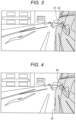
- Fig. 3 is a view illustrating an example of an entire left rear side image of a variation.
- a left partial image S2 excluding an end S 1 on the distant view side (side far from the left camera 10L) of the left side surface of the vehicle body is the target of the blur processing.
- the entirety of the end S 1 and the left partial image S2 put together corresponds to the left partial image S illustrated in Fig. 2A and 2B .
- a clear image of this end S 1 in focus similarly to the distant view behind the own vehicle makes it easily understood the boundary between the left side surface of the vehicle body and the others, and makes it easily grasped the relative distance between the own vehicle and the succeeding vehicle traveling behind the own vehicle.
- Fig. 4 is a view illustrating an example of an entire left rear side image of another variation.
- a left partial image S4 excluding a tire S3 on the left side surface of the vehicle body is the target of the blur processing.
- the entirety of the tire S3 and the left partial image S4 put together corresponds to the left partial image S illustrated in Fig. 2A and 2B .
- sight of the clear image of the tire in the driver's field of view facilitates the driving operation at the time of pulling the own vehicle over or reversing the own vehicle.
- Fig. 5 is a view illustrating an example of an entire left rear side image of another variation.
- the left partial image corresponding to the left side surface of the vehicle body includes three left partial images S51, S52, and S53, and the degree of blurring is increased as getting closer to the left camera 10L. That is, the left partial image S51 closest to the left camera 10L has the largest degree of blurring, the left partial image S52 closest next has the second largest degree of blurring, and the farthest left partial image S53 has the smallest degree of blurring.
- the driver is looking at a distant vehicle or the like, an object closer to the driver is less in focus.
- the blurring method appropriate to the characteristics of human eyes can further reduce the feeling of strangeness at the time of viewing the entire left rear side image.
- the degree of blurring changes in three steps, but may change in two steps, four steps or more, or continuously.
- Fig. 6 is a view illustrating the configuration of a vehicle rear side image display device of another variation.
- a vehicle rear side image display device 1A of the variation (variation 4) illustrated in Fig. 6 is different from the vehicle rear side image display device 1 illustrated in Fig. 1 in that vehicle information including a traveling speed, a shift lever position, and the like of the vehicle is input to each of the left blur processing unit 32L and the right blur processing unit 32R.
- vehicle information is created and input by a vehicle control device that comprehensively controls the vehicle, for example, but a result of individually detecting a traveling speed, a shift lever position, and the like may be directly input.
- the left blur processing unit 32L and the right blur processing unit 32R to which such vehicle information is input perform blur processing by setting the degree of blurring of the left and right partial images to be larger as the speed of the own vehicle is higher. As the speed increases, it is necessary to pay attention to approach of a distant succeeding vehicle particularly at the time of high-speed traveling. Therefore, by increasing the degree of blurring of the image of the vicinity of the own vehicle, it is possible to encourage a gaze to the distant succeeding vehicle or the like.
- the left blur processing unit 32L and the right blur processing unit 32R to which such vehicle information is input perform blur processing by setting the degree of blurring of the left and right partial images to be smaller when the own vehicle moves rearward than when the own vehicle moves forward.
- the degree of blurring of this region facilitates the driving operation at the time of moving the own vehicle rearward.
- the imaging means when the rear side image imaged by the imaging means is displayed, by not displaying an in-focus image of the entire imaging range but clearly displaying a region corresponding to a distant view that the user (driver) is to view and displaying, in a blurring manner, a region closer than that
- This can provide a display image in a blurred manner in accordance with the distance as in a case where the user views a door mirror having a mirror surface, prevent a loss of a feeling of depth, and display an image free from a feeling of strangeness.
Landscapes
- Engineering & Computer Science (AREA)
- Multimedia (AREA)
- Mechanical Engineering (AREA)
- Closed-Circuit Television Systems (AREA)
Applications Claiming Priority (1)
| Application Number | Priority Date | Filing Date | Title |
|---|---|---|---|
| JP2022143403A JP2024039101A (ja) | 2022-09-09 | 2022-09-09 | 車両用後側方画像表示装置 |
Publications (2)
| Publication Number | Publication Date |
|---|---|
| EP4339027A1 true EP4339027A1 (de) | 2024-03-20 |
| EP4339027B1 EP4339027B1 (de) | 2025-10-01 |
Family
ID=87863348
Family Applications (1)
| Application Number | Title | Priority Date | Filing Date |
|---|---|---|---|
| EP23193770.7A Active EP4339027B1 (de) | 2022-09-09 | 2023-08-28 | Fahrzeugheckbildanzeigevorrichtung |
Country Status (2)
| Country | Link |
|---|---|
| EP (1) | EP4339027B1 (de) |
| JP (1) | JP2024039101A (de) |
Citations (5)
| Publication number | Priority date | Publication date | Assignee | Title |
|---|---|---|---|---|
| JP2014116756A (ja) | 2012-12-07 | 2014-06-26 | Toyota Motor Corp | 周辺監視システム |
| EP3276252A1 (de) * | 2015-03-23 | 2018-01-31 | Koito Manufacturing Co., Ltd. | Bildaufnahmevorrichtung für ein fahrzeug, lampenfassung für ein fahrzeug und elektronische steuereinheit |
| WO2018020936A1 (ja) * | 2016-07-28 | 2018-02-01 | カルソニックカンセイ株式会社 | 車両用周辺監視装置および車両周辺監視方法 |
| DE102020006720A1 (de) * | 2020-11-02 | 2021-01-14 | Daimler Ag | Verfahren zur Lokalisierung einer Silhouette eines Fahrzeuggespanns in von einer Fahrzeugaußenkamera erzeugten Kamerabildern und Fahrzeug |
| US11256931B2 (en) * | 2010-04-19 | 2022-02-22 | SMR Patent S.à.r.l | Rearview device simulation |
-
2022
- 2022-09-09 JP JP2022143403A patent/JP2024039101A/ja active Pending
-
2023
- 2023-08-28 EP EP23193770.7A patent/EP4339027B1/de active Active
Patent Citations (5)
| Publication number | Priority date | Publication date | Assignee | Title |
|---|---|---|---|---|
| US11256931B2 (en) * | 2010-04-19 | 2022-02-22 | SMR Patent S.à.r.l | Rearview device simulation |
| JP2014116756A (ja) | 2012-12-07 | 2014-06-26 | Toyota Motor Corp | 周辺監視システム |
| EP3276252A1 (de) * | 2015-03-23 | 2018-01-31 | Koito Manufacturing Co., Ltd. | Bildaufnahmevorrichtung für ein fahrzeug, lampenfassung für ein fahrzeug und elektronische steuereinheit |
| WO2018020936A1 (ja) * | 2016-07-28 | 2018-02-01 | カルソニックカンセイ株式会社 | 車両用周辺監視装置および車両周辺監視方法 |
| DE102020006720A1 (de) * | 2020-11-02 | 2021-01-14 | Daimler Ag | Verfahren zur Lokalisierung einer Silhouette eines Fahrzeuggespanns in von einer Fahrzeugaußenkamera erzeugten Kamerabildern und Fahrzeug |
Also Published As
| Publication number | Publication date |
|---|---|
| JP2024039101A (ja) | 2024-03-22 |
| EP4339027B1 (de) | 2025-10-01 |
Similar Documents
| Publication | Publication Date | Title |
|---|---|---|
| US9100554B2 (en) | Method for displaying an image on a display device in a vehicle, driver assistance system and vehicle | |
| CN102823240B (zh) | 车辆驾驶辅助装置 | |
| EP2068189A3 (de) | Head-up-Anzeigevorrichtung für ein Fahrzeug | |
| JP4699054B2 (ja) | 車両周囲監視装置 | |
| WO2003044738A3 (en) | Method and system for improving car safety using image-enhancement | |
| EP3738101B1 (de) | Verfahren zur erzeugung einer repräsentation einer umgebung durch verschieben einer virtuellen kamera zu einem innenspiegel eines kraftfahrzeugs sowie kameravorrichtung | |
| EP3496996B1 (de) | Verfahren zur unterstützung des fahrers eines kraftfahrzeugs beim manövrieren des kraftfahrzeugs mit einem anhänger, fahrerassistenzsystem sowie fahrzeug-anhänger-kombination | |
| EP2884735A1 (de) | Verfahren zum Betreiben eines Rückansichtskamerasystems eines Kraftfahrzeugs, Rückansichtskamerasystem und Kraftfahrzeug | |
| EP3166307B1 (de) | Erfassungsvorrichtung für ein kraftfahrzeug, fahrerassistenzsystem sowie kraftfahrzeug | |
| JP2010105443A (ja) | 視覚支援装置 | |
| JP6284980B2 (ja) | 主ミラーおよび広角ミラーの法的に定められた視野を表示するための商用車用の視覚システム | |
| EP4339027A1 (de) | Fahrzeugheckbildanzeigevorrichtung | |
| US10819917B2 (en) | Vehicle image processing system | |
| US10737725B2 (en) | System and method for assisting parallel parking using orthogonal projection | |
| WO2019039090A1 (ja) | 電子ミラーシステム | |
| JP6754993B2 (ja) | 車載映像表示装置、車載映像表示方法、およびプログラム | |
| WO2014010179A1 (ja) | 車両用視界支援装置 | |
| DE102016204795B4 (de) | Kraftfahrzeug mit einer Anzeigevorrichtung sowie Verfahren zum Betrieb eines Kraftfahrzeuges | |
| JP6747349B2 (ja) | 運転支援装置、運転支援方法およびプログラム | |
| EP4534351A1 (de) | Aktivierung und optimierung eines nachtmodus bei kameraüberwachungsanwendungen | |
| JP2022101751A (ja) | 車両用後方画像表示装置 | |
| JP2024147851A (ja) | 後方画像表示装置 | |
| JP2006176054A (ja) | 車両用表示装置 | |
| CN118264773A (zh) | 车载视频采集系统、视野联动方法及可穿戴式电子设备 | |
| WO2019149499A1 (en) | Method for representing an environmental region of a motor vehicle with an image window in an image, computer program product as well as display system |
Legal Events
| Date | Code | Title | Description |
|---|---|---|---|
| PUAI | Public reference made under article 153(3) epc to a published international application that has entered the european phase |
Free format text: ORIGINAL CODE: 0009012 |
|
| STAA | Information on the status of an ep patent application or granted ep patent |
Free format text: STATUS: THE APPLICATION HAS BEEN PUBLISHED |
|
| AK | Designated contracting states |
Kind code of ref document: A1 Designated state(s): AL AT BE BG CH CY CZ DE DK EE ES FI FR GB GR HR HU IE IS IT LI LT LU LV MC ME MK MT NL NO PL PT RO RS SE SI SK SM TR |
|
| STAA | Information on the status of an ep patent application or granted ep patent |
Free format text: STATUS: REQUEST FOR EXAMINATION WAS MADE |
|
| 17P | Request for examination filed |
Effective date: 20240909 |
|
| RBV | Designated contracting states (corrected) |
Designated state(s): AL AT BE BG CH CY CZ DE DK EE ES FI FR GB GR HR HU IE IS IT LI LT LU LV MC ME MK MT NL NO PL PT RO RS SE SI SK SM TR |
|
| GRAP | Despatch of communication of intention to grant a patent |
Free format text: ORIGINAL CODE: EPIDOSNIGR1 |
|
| STAA | Information on the status of an ep patent application or granted ep patent |
Free format text: STATUS: GRANT OF PATENT IS INTENDED |
|
| INTG | Intention to grant announced |
Effective date: 20250415 |
|
| GRAS | Grant fee paid |
Free format text: ORIGINAL CODE: EPIDOSNIGR3 |
|
| GRAA | (expected) grant |
Free format text: ORIGINAL CODE: 0009210 |
|
| STAA | Information on the status of an ep patent application or granted ep patent |
Free format text: STATUS: THE PATENT HAS BEEN GRANTED |
|
| P01 | Opt-out of the competence of the unified patent court (upc) registered |
Free format text: CASE NUMBER: UPC_APP_2562_4339027/2025 Effective date: 20250806 |
|
| AK | Designated contracting states |
Kind code of ref document: B1 Designated state(s): AL AT BE BG CH CY CZ DE DK EE ES FI FR GB GR HR HU IE IS IT LI LT LU LV MC ME MK MT NL NO PL PT RO RS SE SI SK SM TR |
|
| REG | Reference to a national code |
Ref country code: GB Ref legal event code: FG4D Ref country code: CH Ref legal event code: F10 Free format text: ST27 STATUS EVENT CODE: U-0-0-F10-F00 (AS PROVIDED BY THE NATIONAL OFFICE) Effective date: 20251001 |
|
| REG | Reference to a national code |
Ref country code: IE Ref legal event code: FG4D |
|
| REG | Reference to a national code |
Ref country code: DE Ref legal event code: R096 Ref document number: 602023007115 Country of ref document: DE |
|
| REG | Reference to a national code |
Ref country code: NL Ref legal event code: MP Effective date: 20251001 |