EP4338880B1 - Schweiss- oder additive fertigungsbrenner mit schutzgasabschirmung - Google Patents
Schweiss- oder additive fertigungsbrenner mit schutzgasabschirmung Download PDFInfo
- Publication number
- EP4338880B1 EP4338880B1 EP23192703.9A EP23192703A EP4338880B1 EP 4338880 B1 EP4338880 B1 EP 4338880B1 EP 23192703 A EP23192703 A EP 23192703A EP 4338880 B1 EP4338880 B1 EP 4338880B1
- Authority
- EP
- European Patent Office
- Prior art keywords
- shielding gas
- welding
- torch
- additive manufacturing
- nozzle
- Prior art date
- Legal status (The legal status is an assumption and is not a legal conclusion. Google has not performed a legal analysis and makes no representation as to the accuracy of the status listed.)
- Active
Links
Images


Classifications
-
- B—PERFORMING OPERATIONS; TRANSPORTING
- B23—MACHINE TOOLS; METAL-WORKING NOT OTHERWISE PROVIDED FOR
- B23K—SOLDERING OR UNSOLDERING; WELDING; CLADDING OR PLATING BY SOLDERING OR WELDING; CUTTING BY APPLYING HEAT LOCALLY, e.g. FLAME CUTTING; WORKING BY LASER BEAM
- B23K9/00—Arc welding or cutting
- B23K9/24—Features related to electrodes
- B23K9/28—Supporting devices for electrodes
- B23K9/29—Supporting devices adapted for making use of shielding means
- B23K9/291—Supporting devices adapted for making use of shielding means the shielding means being a gas
- B23K9/295—Supporting devices adapted for making use of shielding means the shielding means being a gas using consumable electrode-wire
-
- B—PERFORMING OPERATIONS; TRANSPORTING
- B23—MACHINE TOOLS; METAL-WORKING NOT OTHERWISE PROVIDED FOR
- B23K—SOLDERING OR UNSOLDERING; WELDING; CLADDING OR PLATING BY SOLDERING OR WELDING; CUTTING BY APPLYING HEAT LOCALLY, e.g. FLAME CUTTING; WORKING BY LASER BEAM
- B23K9/00—Arc welding or cutting
- B23K9/16—Arc welding or cutting making use of shielding gas
- B23K9/164—Arc welding or cutting making use of shielding gas making use of a moving fluid
-
- B—PERFORMING OPERATIONS; TRANSPORTING
- B23—MACHINE TOOLS; METAL-WORKING NOT OTHERWISE PROVIDED FOR
- B23K—SOLDERING OR UNSOLDERING; WELDING; CLADDING OR PLATING BY SOLDERING OR WELDING; CUTTING BY APPLYING HEAT LOCALLY, e.g. FLAME CUTTING; WORKING BY LASER BEAM
- B23K9/00—Arc welding or cutting
- B23K9/16—Arc welding or cutting making use of shielding gas
- B23K9/167—Arc welding or cutting making use of shielding gas and of a non-consumable electrode
-
- B—PERFORMING OPERATIONS; TRANSPORTING
- B23—MACHINE TOOLS; METAL-WORKING NOT OTHERWISE PROVIDED FOR
- B23K—SOLDERING OR UNSOLDERING; WELDING; CLADDING OR PLATING BY SOLDERING OR WELDING; CUTTING BY APPLYING HEAT LOCALLY, e.g. FLAME CUTTING; WORKING BY LASER BEAM
- B23K9/00—Arc welding or cutting
- B23K9/16—Arc welding or cutting making use of shielding gas
- B23K9/173—Arc welding or cutting making use of shielding gas and of a consumable electrode
-
- B—PERFORMING OPERATIONS; TRANSPORTING
- B23—MACHINE TOOLS; METAL-WORKING NOT OTHERWISE PROVIDED FOR
- B23K—SOLDERING OR UNSOLDERING; WELDING; CLADDING OR PLATING BY SOLDERING OR WELDING; CUTTING BY APPLYING HEAT LOCALLY, e.g. FLAME CUTTING; WORKING BY LASER BEAM
- B23K9/00—Arc welding or cutting
- B23K9/24—Features related to electrodes
- B23K9/26—Accessories for electrodes, e.g. ignition tips
-
- B—PERFORMING OPERATIONS; TRANSPORTING
- B23—MACHINE TOOLS; METAL-WORKING NOT OTHERWISE PROVIDED FOR
- B23K—SOLDERING OR UNSOLDERING; WELDING; CLADDING OR PLATING BY SOLDERING OR WELDING; CUTTING BY APPLYING HEAT LOCALLY, e.g. FLAME CUTTING; WORKING BY LASER BEAM
- B23K9/00—Arc welding or cutting
- B23K9/24—Features related to electrodes
- B23K9/28—Supporting devices for electrodes
- B23K9/29—Supporting devices adapted for making use of shielding means
- B23K9/291—Supporting devices adapted for making use of shielding means the shielding means being a gas
- B23K9/296—Supporting devices adapted for making use of shielding means the shielding means being a gas using non-consumable electrodes
-
- B—PERFORMING OPERATIONS; TRANSPORTING
- B23—MACHINE TOOLS; METAL-WORKING NOT OTHERWISE PROVIDED FOR
- B23K—SOLDERING OR UNSOLDERING; WELDING; CLADDING OR PLATING BY SOLDERING OR WELDING; CUTTING BY APPLYING HEAT LOCALLY, e.g. FLAME CUTTING; WORKING BY LASER BEAM
- B23K9/00—Arc welding or cutting
- B23K9/32—Accessories
- B23K9/325—Devices for supplying or evacuating shielding gas
Definitions
- the present invention relates to torches for gas-shielded arc welding and/or metal additive manufacturing operations, and more particularly to a welding or metal additive manufacturing torch according to the preamble of claim 1 (see for example US 4 529 863 A ).
- Gas-shielded welding processes such as gas metal arc welding (GMAW) metal-cored arc welding (MCAW), gas tungsten arc welding (GTAW) and sometimes flux-cored arc welding (FCAW), employ a shielding gas to protect the welding arc and weld puddle from the surrounding air.
- the shielding gas prevents, or shields, the weld zone from atmospheric oxygen, which causes oxidation, and other atmospheric contaminants.
- a high flow rate of shielding gas will increase the amount of shielding gas discharged during welding.
- a high flow rate of shielding gas can also lead to porosity in the completed weld due to turbulence and the gas flow disrupting the weld pool.
- a high flow rate of shielding gas also increases the consumption rate of the shielding gas which raises the cost of the welding operation.
- a more laminar flow of shielding gas during the welding operation, rather than a turbulent flow, would be desirable as it is less disruptive to the weld pool and can allow for lower gas flow rates and less consumption of shielding gas.
- a more laminar flow of shielding gas also introduces less undesirable reactive gases from the atmosphere into the gas column shielding the weld zone.
- a more laminar shielding gas flow can also allow for the capability of operating with a longer electrical stickout.
- a welding system includes an electrically insulated sleeve and a perforated screen disposed adjacent to the electrically insulated sleeve.
- the perforated screen is configured to be captured removably between a nozzle and a contact tip of a torch head, and the perforated screen is configured to be installed and removed independent of the nozzle.
- Document US 2002/134760 A1 discloses a gas lens assembly for use in a gas shielded welding torch to provide laminar gas flow to the weld puddle.
- the assembly includes a plurality of annular fine mesh inner filter screens mounted in fixed axially spaced disposition in a gas chamber formed between the lens body and lens sleeve.
- the filter screens are preferably spaced apart a predetermined distance by a plurality of wave-shaped open mesh spacer discs disposed in a sandwich configuration between the filter screens.
- a stack of adjacently disposed outer filter screens are mounted in the gas chamber outwardly of the fine mesh filter screens. Each of the outer screens in the stack is individually removable such that the outermost screen can be readily peeled from the stack when damaged by spatter or heat to maintain the laminar gas flow through the assembly and prolong the useful life of the assembly.
- Document EP 3 670 056 A2 discloses a welding or additive manufacturing contact tip including an electrically conductive body extending from a proximal end of the body to a distal end of the body.
- the body forms a first bore terminating at a first exit orifice at a distal end face of the body, and a second bore terminating at a second exit orifice at the distal end face of the body.
- the first and second exit orifices are separated from each other by a distance configured to facilitate formation of a bridge droplet between a first wire electrode delivered through the first bore and a second wire electrode delivered through the second bore during a deposition operation.
- Document US 3 053 968 A discloses a gas-shielded arc torch comprising an elongated electrode, an electrical contact for said electrode, means supporting said contact, said means having an annular chamber and arc shielding gas passages for delivering are shielding gas to such chamber, and a gas lens surrounding said electrode and constituting a wall of such chamber, for fully expanding and directing such gas around said electrode in the direction of the arc end thereof.
- a welding or metal additive manufacturing torch is defined in claim 1.
- the present invention relates to torches for gas-shielded arc welding and/or metal additive manufacturing operations.
- the present invention will now be described with reference to the drawings, wherein like reference numerals are used to refer to like elements throughout. It is to be appreciated that the various drawings are not necessarily drawn to scale from one figure to another nor inside a given figure, and in particular that the size of the components are arbitrarily drawn for facilitating the understanding of the drawings. In the following description, for purposes of explanation, numerous specific details are set forth in order to provide a thorough understanding of the present invention.
- GMAW gas metal arc welding
- FCAW flux-cored arc welding
- MCAW metal-cored arc welding
- SAW submerged arc welding
- GMAW-P pulse GMAW
- GMAW-S short circuit GMAW
- embodiments of the present invention can be used in manual, semi-automatic and robotic welding operations.
- Embodiments of the present invention can also be used in metal deposition operations that are similar to welding, such as metal additive manufacturing (3D printing), hardfacing, and cladding.
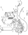
- welding power supply 102 power cables 108, and control cable 110 can have any configuration suitable for supplying power and welding controls within the welding system 100.
- wire feeder 104 and welding power supply 102 are shown as two separate devices interconnected by cabling, the welding power supply and wire feeder could be integrated into a single welding machine.
- gas conduit 116 and regulator 118 are configured to connect the shielding gas supply 106 to the wire feeder 104.
- the shielding gas supply 106 may include inert gases, active gases, or a combination of both, including but not limited to argon, helium, carbon dioxide, argon and helium, argon and hydrogen, and other gas combinations.
- the gas supply may be any gas or combination of gases configured to shield a weld from the atmosphere.
- wire feeder 104 may include a housing 120, gear box 122, wire spool assembly 124, and user interface 126. Extending from the gear box 122 is a hose 128 that is configured to connect to a welding torch 130.
- the housing 120 may be connected to the user interface 126 and gear box 122.
- the control cable 110 and power cable 114 extending from welding power supply 102, and the gas conduit 116 extending from gas supply 106 are configured to connect to housing 120, gear box 122, and hose 128.
- Gear box 122 includes at least a drive motor and a plurality of rollers that advance and retract a wire electrode drawn from a spool (not shown) mounted on the spool assembly 124 or drawn from a bulk package, such as a box or drum. Extending between the gear box 122 and the welding torch 130 is the hose 128.
- the hose 128 provides a conduit for the welding electrode and shielding gas and conducts the welding waveforms to the torch 130.
- the hose 128 can conduct a trigger signal from the torch 130 to the wire feeder 104 and to the welding power supply 102 to control feeding of the wire electrode and the provision of the welding waveforms and shielding gas to the torch.
- the hose 128 and welding torch 130 may have any configuration suitable for supplying welding wire, shielding gas, and controls between the torch and wire feeder 102.
- the torch 130 can include a contact tip for conducting the welding waveforms from the wire feeder 104 to the wire electrode, and a shielding gas diffuser and nozzle to direct the shielding gas around the arc and toward the molten puddle.
- the torch 130 can also include a shielding gas lens to create a more laminar flow of shielding gas around the weld zone and molten puddle. The shielding gas lens is discussed in detail below.
- a schematic view of a distal portion of a gas-shielded welding torch 130 is shown in position above workpiece W.
- the distal end of the torch handle 200 is shown in Fig. 2 along with a gooseneck 202 extending from the torch handle.
- Welding torch 130 is supplied with one or more wire electrodes 204 (e.g., steel, aluminum, alloys, composites, cored, etc., or other welding wire known to those in the art) from a wire supply spool, drum, etc. by a wire feeder.
- the wire feeder not only regulates the rate at which welding wire 204 is fed through the torch 130, but it can also control the flow of shielding gas from a gas source to the torch.
- the flow of shielding gas is often turbulent, in particular at high flow rates, which is undesirable.
- Turbulent shielding gas flows can draw contaminants from the ambient air into the weld zone and can disrupt the weld pool leading to porosity.
- Turbulent shielding gas flows also reduce the amount of electrical stickout that can be employed during welding.
- High shielding gas flow rates, which are often turbulent, increase the consumption rate of the shielding gas which raises the cost of the welding operation.
- a laminar flow of shielding gas from the torch 130 is preferable to a turbulent flow of gas as it allows for lower gas flow rates and reduced porosity while adequately protecting the weld zone.
- a laminar flow of shielding gas also allows for the use of a longer electrical stickout when the laminar flow is maintained for a longer distance from the nozzle 206 as compared to typical welding operations.
- the torch 130 includes a shielding gas lens 211.
- the shielding gas lens 211 includes one or more annular screens having a mesh.
- the diffuser 208 has a plurality of shielding gas discharge holes 212 spaced annularly around the diffuser.
- the shielding gas lens 211 and its annular screen(s) are located within the nozzle 206 distal of the shielding gas discharge holes 212.
- the shielding gas flows through the mesh screen(s) of the shielding gas lens 211 after being discharged from the shielding gas discharge holes 212.
- the shielding gas 214 flowing through the lens 211 is generally laminar as shown schematically in Fig. 3 .
- Figure 3 also shows a dual wire welding process in which two wire electrodes are simultaneously fed through the contact tip.
- a filtered GMAW nozzle setup as shown can improve the gas coverage during welding by distributing laminar gas flow around the electrodes and onto the weld puddle.
- the laminar gas flow 214 can help to stabilize the welding arc when using high deposition welding processes such as multi-wire welding. Not only does the weld puddle need shielding, but the arc and droplets that travel through the arc need stable shielding gas coverage, which is provided by a laminar gas flow 214.
- a laminar gas flow 214 also provides the capability to run lower shielding gas flow rates and conserve shielding gas versus running extremely high flow rates (which may not even be available when using a standard gas regulator rather than a high flow regulator). A more stable delivery of shielding gas flow will correspond with a weld that will yield less porosity and better visual aesthetics.
- shielding gases conforming to the American Welding Society (AWS) A5.32 specification become more accurate at fill plants
- An example would be distributors that offer gas cylinders with 100% accurate shielding blends. This in turn will correspond with the delivery of the shielding gas at the nozzle of the welding torch.
- a filtered, stable, generally laminar delivery of shielding gas will deliver a more precise droplet of metal through the arc, especially when using waveform control technology.
- Aluminum GMAW and critical alloy welding applications that use high shielding gas flow rates or are sensitive to changes or lack of shielding gas coverage could also benefit from the use of a shielding gas lens 211 in the torch.
- FIG. 4 shows the shielding gas lens 211 in detail.
- the shielding gas lens 211 has one or more annular screens 216, 218.
- the annular screens 216, 218 are located within the nozzle distal of the diffuser's shielding gas discharge holes.
- the annular screens 216, 218 extend radially within the nozzle of the torch, between the diffuser and the nozzle, to filter the shielding gas flow from the diffuser's gas discharge holes.
- the annular screens 216, 218 have a mesh size suitable to provide a generally laminar flow of shielding gas from the torch at a desired gas flow rate and distance from the end of the nozzle.
- the shielding gas lens 211 shown in Fig. 4 has two annular screens 216, 218, it is to be appreciated that the gas lens could have a single screen or more than two screens if desired.
- the shielding gas lens 211 can include a central hub 220 that is attached to the annular screens 216, 218.
- the central hub 220 can be mounted on the diffuser distal of the shielding gas discharge holes, mounted on the contact tip which is located distal of the shielding gas discharge holes, or mounted between a portion of the contact tip and the diffuser.
- attaching the contact tip to the diffuser can hold the gas lens 211 in place within the nozzle by clamping the gas lens between a portion of the contact tip and the end face of the diffuser.
- the screens 216, 218 and hub 220 are made from suitable metallic materials.
- the hub 220 and screens 216, 218 could be made from other appropriate materials suitable for exposure to the high temperatures at the distal end of the torch.
- the hub could be made of an electrically-insulating material such as a ceramic.
- Figure 5 shows an exploded view of the distal end of an example torch that includes the shielding gas lens 211.
- the nozzle 206 can be attached to the torch's gooseneck via an insulator 222.
- the metallic nozzle 206 in particular the exposed outer surface of the nozzle
- Located inside of the nozzle 206 are the diffuser 208, contact tip 210, and shielding gas lens 211.
- the shielding gas lens 211 can be located at various positions within the nozzle downstream of the shielding gas discharge holes.
- the shielding gas lens 211 could be mounted on the diffuser 208.
- Figure 6 shows the distal portion of the welding torch 130 with the shielding gas lens 211 located between the diffuser 208 and a portion of the contact tip 210 that is distal of the diffuser.
- the shielding gas lens 211 is clamped between the end face of the diffuser 208 and the portion of the contact tip 210 that is distal of the diffuser.
- the contact tip 210 can include a shank that is inserted (e.g., threaded) into the diffuser 208 and a shoulder that normally seats against the end face of the diffuser.
- the shoulder on the contact tip 210 can clamp the shielding gas lens 211 against the diffuser 208 as the contact tip is threaded into the diffuser.
- the central hub of the shielding gas lens 211 can be located between the shoulder of the contact tip 210 and the end face of the diffuser 208.
- the outer surface of the nozzle 206 should be electrically insulated from the contact tip 210 and the diffuser 208, which can be energized during welding.
- the annular screen(s) of the shielding gas lens 211 extend radially outward from the diffuser 208 toward the nozzle 206 and across the air gap that normally exists between the diffuser/contact tip and the nozzle.
- the nozzle 206 is typically made of a metallic material.
- the annular screen(s) of the shielding gas lens 211 can also be made of a metallic material and be electrically conductive.
- Figure 8 shows schematically a contact tip 226 for a dual wire welding operation.
- the use of a shielding gas lens in a dual wire welding operation can be beneficial because of the high deposition rate and molten puddle size and the need for adequate shielding gas coverage.
- the use of a shielding gas lens to provide a more laminar shielding gas flow in a dual wire welding operation can allow for lower shielding gas flow rates (CFH) during welding and provide reduced porosity, as compared to conventional dual wire welding operations.
- the contact tip 226 for a dual wire welding operation has a first bore and exit orifice 228 for a first wire electrode 230, and a second bore and exit orifice 232 for a second wire electrode 234. Welding current is simultaneously conducted to both wire electrodes 230, 234 through the contact tip 226 during the welding operation.
Landscapes
- Engineering & Computer Science (AREA)
- Physics & Mathematics (AREA)
- Plasma & Fusion (AREA)
- Mechanical Engineering (AREA)
- Arc Welding In General (AREA)
Claims (15)
- Brenner zum Schweißen oder zur additiven Metallfertigung (130), umfassend:- eine Düse (206);- einen Schutzgasdiffusor (208), der sich innerhalb der Düse (206) befindet und eine Mehrzahl von Schutzgasauslasslöchern (212) aufweist, die ringförmig um den Schutzgasdiffusor (208) herum beabstandet sind;wobei der Brenner (130) gekennzeichnet ist durch:- eine Kontaktspitze (210), die sich von dem Schutzgasdiffusor (208) distal zu den Schutzgasauslasslöchern (212) erstreckt;- eine ringförmige Abschirmung (216, 218), die sich distal von den Schutzgasauslasslöchern (212) befindet, wobei die ringförmige Abschirmung (216, 218) von mindestens einem von dem Schutzgasdiffusor (208) und einer Außenfläche der Düse (206) elektrisch isoliert ist, wobei sich die ringförmige Abschirmung (216, 218) radial zwischen der Düse (206) und dem Schutzgasdiffusor (208) erstreckt.
- Brenner zum Schweißen oder zur additiven Metallfertigung (130) nach Anspruch 1, wobei die ringförmige Abschirmung (216, 218) eine auf dem Schutzgasdiffusor montierte zentrale Nabe aufweist, wobei bevorzugt die zentrale Nabe die ringförmige Abschirmung (216, 218) elektrisch von dem Schutzgasdiffusor isoliert.
- Brenner zum Schweißen oder zur additiven Metallfertigung (130) nach Anspruch 1 oder 2, wobei die ringförmige Abschirmung (216, 218) an dem Schutzgasdiffusor befestigt ist.
- Brenner zum Schweißen oder zur additiven Metallfertigung (130) nach Anspruch 1, ferner umfassend ferner eine an der ringförmigen Abschirmung (216, 218) befestigte zentrale Nabe, wobei die zentrale Nabe die ringförmige Abschirmung (216, 218) elektrisch von dem Schutzgasdiffusor isoliert.
- Brenner zum Schweißen oder zur additiven Metallfertigung (130) nach Anspruch 1, ferner umfassend einen elektrischen Isolator, der sich radial zwischen der ringförmigen Abschirmung (216, 218) und der Düse (206) befindet.
- Brenner zum Schweißen oder zur additiven Metallfertigung (130) nach Anspruch 1, wobei die ringförmige Abschirmung (216, 218) aus einer von einer Mehrzahl von metallischen ringförmigen Abschirmungen (216, 218) gebildet ist, die in einer Schutzgaslinse umfasst sind, wobei die Mehrzahl von metallischen ringförmigen Abschirmungen (216, 218) sich radial zwischen der Düse (206) und dem Schutzgasdiffusor (208) erstrecken und sich distal von den Schutzgasauslasslöchern (212) befinden, wobei die Mehrzahl von metallischen ringförmigen Abschirmungen (216, 218) elektrisch von mindestens einem von dem Schutzgasdiffusor (208) und einer Außenfläche der Düse (206) isoliert sind.
- Brenner zum Schweißen oder zur additiven Metallfertigung (130) nach Anspruch 6, wobei die Schutzgaslinse eine an dem Schutzgasdiffusor montierte zentrale Nabe aufweist, wobei bevorzugt die zentrale Nabe die Mehrzahl von metallischen ringförmigen Abschirmungen (216, 218) elektrisch von dem Schutzgasdiffusor isoliert.
- Brenner zum Schweißen oder zur additiven Metallfertigung (130) nach Anspruch 6 oder 7, wobei die Schutzgaslinse an dem Schutzgasdiffusor befestigt ist.
- Brenner zum Schweißen oder zur additiven Metallfertigung (130) nach Anspruch 6, 7 oder 8, wobei die Schutzgaslinse eine an der Mehrzahl von metallischen ringförmigen Abschirmungen (216, 218) befestigte zentrale Nabe aufweist, wobei die zentrale Nabe die Mehrzahl von metallischen ringförmigen Abschirmungen (216, 218) elektrisch von dem Schutzgasdiffusor isoliert.
- Brenner zum Schweißen oder zur additiven Metallfertigung (130) nach einem der Ansprüche 6 bis 9, ferner umfassend einen elektrischen Isolator, der sich radial zwischen der Mehrzahl von metallischen ringförmigen Abschirmungen (216, 218) und der Düse (206) befindet.
- Brenner zum Schweißen oder zur additiven Metallfertigung (130) nach Anspruch 1, wobei die Kontaktspitze (210) eine erste Austrittsöffnung für eine erste Drahtelektrode und eine zweite Austrittsöffnung für eine zweite Drahtelektrode aufweist.
- Brenner zum Schweißen oder zur additiven Metallfertigung (130) nach Anspruch 11, wobei die ringförmige Abschirmung (216, 218) eine an dem Schutzgasdiffusor montierte zentrale Nabe aufweist, wobei bevorzugt die zentrale Nabe die ringförmige Abschirmung (216, 218) elektrisch von dem Schutzgasdiffusor isoliert.
- Brenner zum Schweißen oder zur additiven Metallfertigung (130) nach Anspruch 11 oder 12, wobei die ringförmige Abschirmung (216, 218) an dem Schutzgasdiffusor befestigt ist.
- Brenner zum Schweißen oder zur additiven Metallfertigung (130) nach Anspruch 11, 12 oder 13, ferner umfassend eine an der ringförmigen Abschirmung (216, 218) befestigte zentrale Nabe, wobei die zentrale Nabe die ringförmige Abschirmung (216, 218) elektrisch vom Schutzgasdiffusor isoliert.
- Brenner zum Schweißen oder zur additiven Metallfertigung (130) nach einem der Ansprüche 11 bis 14, ferner umfassend einen elektrischen Isolator, der sich radial zwischen der ringförmigen Abschirmung (216, 218) und der Düse (206) befindet.
Applications Claiming Priority (1)
| Application Number | Priority Date | Filing Date | Title |
|---|---|---|---|
| US17/893,336 US20240066621A1 (en) | 2022-08-23 | 2022-08-23 | Welding torch with shield gas screen |
Publications (3)
| Publication Number | Publication Date |
|---|---|
| EP4338880A1 EP4338880A1 (de) | 2024-03-20 |
| EP4338880C0 EP4338880C0 (de) | 2025-07-02 |
| EP4338880B1 true EP4338880B1 (de) | 2025-07-02 |
Family
ID=87762481
Family Applications (1)
| Application Number | Title | Priority Date | Filing Date |
|---|---|---|---|
| EP23192703.9A Active EP4338880B1 (de) | 2022-08-23 | 2023-08-22 | Schweiss- oder additive fertigungsbrenner mit schutzgasabschirmung |
Country Status (2)
| Country | Link |
|---|---|
| US (1) | US20240066621A1 (de) |
| EP (1) | EP4338880B1 (de) |
Family Cites Families (5)
| Publication number | Priority date | Publication date | Assignee | Title |
|---|---|---|---|---|
| US3053968A (en) * | 1960-04-25 | 1962-09-11 | Union Carbide Corp | Method and apparatus for arc working with gas shields having coherentstreaming |
| US4529863A (en) * | 1983-09-01 | 1985-07-16 | P.P.I. Performance Process International | Gas metal arc welding method |
| US6525288B2 (en) * | 2001-03-20 | 2003-02-25 | Richard B. Rehrig | Gas lens assembly for a gas shielded arc welding torch |
| WO2007030720A1 (en) * | 2005-09-11 | 2007-03-15 | Illinois Tool Works Inc. | Welding torch having nozzle assembly with independently removable components |
| KR102581105B1 (ko) * | 2018-10-26 | 2023-09-20 | 링컨 글로벌, 인크. | 용접 접점 팁 |
-
2022
- 2022-08-23 US US17/893,336 patent/US20240066621A1/en active Pending
-
2023
- 2023-08-22 EP EP23192703.9A patent/EP4338880B1/de active Active
Also Published As
| Publication number | Publication date |
|---|---|
| US20240066621A1 (en) | 2024-02-29 |
| EP4338880C0 (de) | 2025-07-02 |
| EP4338880A1 (de) | 2024-03-20 |
Similar Documents
| Publication | Publication Date | Title |
|---|---|---|
| US5155330A (en) | Method and apparatus for GMAW welding | |
| US9035221B2 (en) | Tandem gas metal arc welding system | |
| EP2379271B1 (de) | Doppeldraht-gmaw-schweissbrenneranordnung und verfahren | |
| US8866036B2 (en) | Welding torch and adapter kit | |
| US20090107958A1 (en) | Torch and Contact Tip for Gas Metal Arc Welding | |
| CN110114179B (zh) | 用于焊接应用的场形成器 | |
| US20060289394A1 (en) | TIG welding or braze welding with metal transfer via a liquid bridge | |
| US20090107970A1 (en) | Method for controlling weld quality | |
| JP2009530112A (ja) | 溶接のための装置及び方法 | |
| US20140263250A1 (en) | Welding diffuser with debris removal | |
| US11484962B2 (en) | Welding torch | |
| US20090071942A1 (en) | Method and apparatus of welding with electrical stickout | |
| JPH04258380A (ja) | 溶接用改良ガスシールド | |
| EP4338880B1 (de) | Schweiss- oder additive fertigungsbrenner mit schutzgasabschirmung | |
| US6437288B1 (en) | Process and unit for the mig welding of aluminum and its alloys | |
| CN111107955A (zh) | 用于热接合的焊炬体 | |
| JPH07256462A (ja) | ガスアーク溶接装置の溶接部の構造 | |
| JP2023097594A (ja) | 溶接トーチ | |
| JP7525549B2 (ja) | アフターシールド治具及び溶接装置 | |
| US20250065431A1 (en) | Protective welding nozzle | |
| US20240217020A1 (en) | Combined Extraction/Shielding Gas Nozzle of an Arc Welding Torch with a Consumable Electrode and Torch Neck Having a Combined Extraction/Shielding Gas Nozzle | |
| US20030132204A1 (en) | Welding head, nozzle and method for powder plasma arc welding (PPAW) | |
| JP2003220472A (ja) | ガスシールドアーク溶接用トーチのノズル | |
| JP2021181100A (ja) | シールド性に優れた多電極ガスシールドアーク溶接用シールド冶具 | |
| KR20200119012A (ko) | Tig 용접용 텅스텐 전극봉 |
Legal Events
| Date | Code | Title | Description |
|---|---|---|---|
| PUAI | Public reference made under article 153(3) epc to a published international application that has entered the european phase |
Free format text: ORIGINAL CODE: 0009012 |
|
| STAA | Information on the status of an ep patent application or granted ep patent |
Free format text: STATUS: THE APPLICATION HAS BEEN PUBLISHED |
|
| AK | Designated contracting states |
Kind code of ref document: A1 Designated state(s): AL AT BE BG CH CY CZ DE DK EE ES FI FR GB GR HR HU IE IS IT LI LT LU LV MC ME MK MT NL NO PL PT RO RS SE SI SK SM TR |
|
| STAA | Information on the status of an ep patent application or granted ep patent |
Free format text: STATUS: REQUEST FOR EXAMINATION WAS MADE |
|
| 17P | Request for examination filed |
Effective date: 20240917 |
|
| RBV | Designated contracting states (corrected) |
Designated state(s): AL AT BE BG CH CY CZ DE DK EE ES FI FR GB GR HR HU IE IS IT LI LT LU LV MC ME MK MT NL NO PL PT RO RS SE SI SK SM TR |
|
| RIC1 | Information provided on ipc code assigned before grant |
Ipc: B23K 9/32 20060101ALI20241211BHEP Ipc: B23K 9/29 20060101ALI20241211BHEP Ipc: B23K 9/26 20060101ALI20241211BHEP Ipc: B23K 9/173 20060101ALI20241211BHEP Ipc: B23K 9/167 20060101AFI20241211BHEP |
|
| GRAP | Despatch of communication of intention to grant a patent |
Free format text: ORIGINAL CODE: EPIDOSNIGR1 |
|
| STAA | Information on the status of an ep patent application or granted ep patent |
Free format text: STATUS: GRANT OF PATENT IS INTENDED |
|
| INTG | Intention to grant announced |
Effective date: 20250129 |
|
| RAP3 | Party data changed (applicant data changed or rights of an application transferred) |
Owner name: LINCOLN GLOBAL, INC. |
|
| GRAS | Grant fee paid |
Free format text: ORIGINAL CODE: EPIDOSNIGR3 |
|
| GRAA | (expected) grant |
Free format text: ORIGINAL CODE: 0009210 |
|
| STAA | Information on the status of an ep patent application or granted ep patent |
Free format text: STATUS: THE PATENT HAS BEEN GRANTED |
|
| AK | Designated contracting states |
Kind code of ref document: B1 Designated state(s): AL AT BE BG CH CY CZ DE DK EE ES FI FR GB GR HR HU IE IS IT LI LT LU LV MC ME MK MT NL NO PL PT RO RS SE SI SK SM TR |
|
| REG | Reference to a national code |
Ref country code: GB Ref legal event code: FG4D |
|
| REG | Reference to a national code |
Ref country code: CH Ref legal event code: EP |
|
| REG | Reference to a national code |
Ref country code: DE Ref legal event code: R096 Ref document number: 602023004473 Country of ref document: DE |
|
| REG | Reference to a national code |
Ref country code: IE Ref legal event code: FG4D |
|
| U01 | Request for unitary effect filed |
Effective date: 20250728 |
|
| U07 | Unitary effect registered |
Designated state(s): AT BE BG DE DK EE FI FR IT LT LU LV MT NL PT RO SE SI Effective date: 20250805 |
|
| PG25 | Lapsed in a contracting state [announced via postgrant information from national office to epo] |
Ref country code: IS Free format text: LAPSE BECAUSE OF FAILURE TO SUBMIT A TRANSLATION OF THE DESCRIPTION OR TO PAY THE FEE WITHIN THE PRESCRIBED TIME-LIMIT Effective date: 20251102 |
|
| PG25 | Lapsed in a contracting state [announced via postgrant information from national office to epo] |
Ref country code: NO Free format text: LAPSE BECAUSE OF FAILURE TO SUBMIT A TRANSLATION OF THE DESCRIPTION OR TO PAY THE FEE WITHIN THE PRESCRIBED TIME-LIMIT Effective date: 20251002 |
|
| PG25 | Lapsed in a contracting state [announced via postgrant information from national office to epo] |
Ref country code: HR Free format text: LAPSE BECAUSE OF FAILURE TO SUBMIT A TRANSLATION OF THE DESCRIPTION OR TO PAY THE FEE WITHIN THE PRESCRIBED TIME-LIMIT Effective date: 20250702 |
|
| PG25 | Lapsed in a contracting state [announced via postgrant information from national office to epo] |
Ref country code: GR Free format text: LAPSE BECAUSE OF FAILURE TO SUBMIT A TRANSLATION OF THE DESCRIPTION OR TO PAY THE FEE WITHIN THE PRESCRIBED TIME-LIMIT Effective date: 20251003 |
|
| PG25 | Lapsed in a contracting state [announced via postgrant information from national office to epo] |
Ref country code: CZ Free format text: LAPSE BECAUSE OF FAILURE TO SUBMIT A TRANSLATION OF THE DESCRIPTION OR TO PAY THE FEE WITHIN THE PRESCRIBED TIME-LIMIT Effective date: 20250702 |
|
| PG25 | Lapsed in a contracting state [announced via postgrant information from national office to epo] |
Ref country code: PL Free format text: LAPSE BECAUSE OF FAILURE TO SUBMIT A TRANSLATION OF THE DESCRIPTION OR TO PAY THE FEE WITHIN THE PRESCRIBED TIME-LIMIT Effective date: 20250702 |
|
| PG25 | Lapsed in a contracting state [announced via postgrant information from national office to epo] |
Ref country code: RS Free format text: LAPSE BECAUSE OF FAILURE TO SUBMIT A TRANSLATION OF THE DESCRIPTION OR TO PAY THE FEE WITHIN THE PRESCRIBED TIME-LIMIT Effective date: 20251002 |
|
| PG25 | Lapsed in a contracting state [announced via postgrant information from national office to epo] |
Ref country code: ES Free format text: LAPSE BECAUSE OF FAILURE TO SUBMIT A TRANSLATION OF THE DESCRIPTION OR TO PAY THE FEE WITHIN THE PRESCRIBED TIME-LIMIT Effective date: 20250702 |