EP4338587B1 - Kraftübertragungssystem für einen mischwagen zur zubereitung von nahrungsmittelmischungen für tiere - Google Patents
Kraftübertragungssystem für einen mischwagen zur zubereitung von nahrungsmittelmischungen für tiere Download PDFInfo
- Publication number
- EP4338587B1 EP4338587B1 EP23196101.2A EP23196101A EP4338587B1 EP 4338587 B1 EP4338587 B1 EP 4338587B1 EP 23196101 A EP23196101 A EP 23196101A EP 4338587 B1 EP4338587 B1 EP 4338587B1
- Authority
- EP
- European Patent Office
- Prior art keywords
- engine
- shaft
- pump
- power transmission
- transmission system
- Prior art date
- Legal status (The legal status is an assumption and is not a legal conclusion. Google has not performed a legal analysis and makes no representation as to the accuracy of the status listed.)
- Active
Links
Images




Classifications
-
- A—HUMAN NECESSITIES
- A01—AGRICULTURE; FORESTRY; ANIMAL HUSBANDRY; HUNTING; TRAPPING; FISHING
- A01K—ANIMAL HUSBANDRY; AVICULTURE; APICULTURE; PISCICULTURE; FISHING; REARING OR BREEDING ANIMALS, NOT OTHERWISE PROVIDED FOR; NEW BREEDS OF ANIMALS
- A01K5/00—Feeding devices for stock or game ; Feeding wagons; Feeding stacks
- A01K5/001—Fodder distributors with mixer or shredder
- A01K5/004—Fodder distributors with mixer or shredder with mixing or shredding element rotating on vertical axis
-
- B—PERFORMING OPERATIONS; TRANSPORTING
- B01—PHYSICAL OR CHEMICAL PROCESSES OR APPARATUS IN GENERAL
- B01F—MIXING, e.g. DISSOLVING, EMULSIFYING OR DISPERSING
- B01F27/00—Mixers with rotary stirring devices in fixed receptacles; Kneaders
- B01F27/80—Mixers with rotary stirring devices in fixed receptacles; Kneaders with stirrers rotating about a substantially vertical axis
- B01F27/92—Mixers with rotary stirring devices in fixed receptacles; Kneaders with stirrers rotating about a substantially vertical axis with helices or screws
- B01F27/922—Mixers with rotary stirring devices in fixed receptacles; Kneaders with stirrers rotating about a substantially vertical axis with helices or screws with two or more helices, e.g. with intermeshing helices
-
- F—MECHANICAL ENGINEERING; LIGHTING; HEATING; WEAPONS; BLASTING
- F16—ENGINEERING ELEMENTS AND UNITS; GENERAL MEASURES FOR PRODUCING AND MAINTAINING EFFECTIVE FUNCTIONING OF MACHINES OR INSTALLATIONS; THERMAL INSULATION IN GENERAL
- F16H—GEARING
- F16H47/00—Combinations of mechanical gearing with fluid clutches or fluid gearing
- F16H47/02—Combinations of mechanical gearing with fluid clutches or fluid gearing the fluid gearing being of the volumetric type
- F16H47/04—Combinations of mechanical gearing with fluid clutches or fluid gearing the fluid gearing being of the volumetric type the mechanical gearing being of the type with members having orbital motion
-
- F—MECHANICAL ENGINEERING; LIGHTING; HEATING; WEAPONS; BLASTING
- F16—ENGINEERING ELEMENTS AND UNITS; GENERAL MEASURES FOR PRODUCING AND MAINTAINING EFFECTIVE FUNCTIONING OF MACHINES OR INSTALLATIONS; THERMAL INSULATION IN GENERAL
- F16H—GEARING
- F16H1/00—Toothed gearings for conveying rotary motion
- F16H1/02—Toothed gearings for conveying rotary motion without gears having orbital motion
- F16H1/20—Toothed gearings for conveying rotary motion without gears having orbital motion involving more than two intermeshing members
- F16H1/22—Toothed gearings for conveying rotary motion without gears having orbital motion involving more than two intermeshing members with a plurality of driving or driven shafts; with arrangements for dividing torque between two or more intermediate shafts
-
- F—MECHANICAL ENGINEERING; LIGHTING; HEATING; WEAPONS; BLASTING
- F16—ENGINEERING ELEMENTS AND UNITS; GENERAL MEASURES FOR PRODUCING AND MAINTAINING EFFECTIVE FUNCTIONING OF MACHINES OR INSTALLATIONS; THERMAL INSULATION IN GENERAL
- F16H—GEARING
- F16H37/00—Combinations of mechanical gearings, not provided for in groups F16H1/00 - F16H35/00
- F16H37/02—Combinations of mechanical gearings, not provided for in groups F16H1/00 - F16H35/00 comprising essentially only toothed or friction gearings
- F16H37/06—Combinations of mechanical gearings, not provided for in groups F16H1/00 - F16H35/00 comprising essentially only toothed or friction gearings with a plurality of driving or driven shafts; with arrangements for dividing torque between two or more intermediate shafts
- F16H37/08—Combinations of mechanical gearings, not provided for in groups F16H1/00 - F16H35/00 comprising essentially only toothed or friction gearings with a plurality of driving or driven shafts; with arrangements for dividing torque between two or more intermediate shafts with differential gearing
- F16H37/0833—Combinations of mechanical gearings, not provided for in groups F16H1/00 - F16H35/00 comprising essentially only toothed or friction gearings with a plurality of driving or driven shafts; with arrangements for dividing torque between two or more intermediate shafts with differential gearing with arrangements for dividing torque between two or more intermediate shafts, i.e. with two or more internal power paths
- F16H37/084—Combinations of mechanical gearings, not provided for in groups F16H1/00 - F16H35/00 comprising essentially only toothed or friction gearings with a plurality of driving or driven shafts; with arrangements for dividing torque between two or more intermediate shafts with differential gearing with arrangements for dividing torque between two or more intermediate shafts, i.e. with two or more internal power paths at least one power path being a continuously variable transmission, i.e. CVT
- F16H2037/088—Power-split transmissions with summing differentials, with the input of the CVT connected or connectable to the input shaft
Definitions
- self-propelled mixer wagons are known, i.e., equipped with engine means thereof, typically an endothermic engine assembly, that make it possible to move the mixer wagon and to actuate the at least one auger.
- engine means thereof typically an endothermic engine assembly
- towed mixer wagons which require a tow vehicle, for example a tractor for moving the mixer wagon.
- Such a tow vehicle must include a power take-off for driving the at least one auger.
- a towed mixer wagon is devoid of engine means thereof.
- power transmission systems comprising a reducer group with a continuously variable transmission (CVT), by virtue of which it is possible to continuously vary the transmission ratio between two limiting values.
- CVT continuously variable transmission
- power transmission systems comprising a hydrostatic type continuously variable reducer group based upon planetary gears.
- the object of the present invention is to present a mixer wagon that meets the aforesaid requirements and overcomes the drawbacks of the prior art.
- a power transmission system for a mixer wagon is indicated in the entirety thereof with the numeral 1.
- the mixer wagon comprises a support frame for supporting the mixer wagon components and systems connecting them therebetween.
- the mixer wagon comprises a mixing tank 110 suitable for containing the mixture ingredients and a mixing assembly 120 comprising at least one auger 125 housed in said mixing tank 110 and suitable for shredding the ingredients of the mixture.
- engine means refers to an operating unit configured for delivering mechanical power.
- engine means refers to an engine assembly included in the mixer wagon, for example, an endothermic engine assembly that is preferably Diesel powered.
- engine means refers to a power take-off included in the towing vehicle, such as a farm tractor.
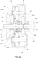
- the reducer group 2 comprises an inlet shaft 21 that extends along inlet shaft axis X-X configured for receiing power from the wagon engine means 160. Additionally, the reducer group 2 comprises an outlet shaft 26 that extends along an outlet shaft axis Y-Y configured for transmitting power to the mixing assembly 120.
- the reducer group 2 comprises a planetary gear 20 comprising a satellite carrier or carrier 22 rigidly connected in rotation to the inlet shaft 21, a crown 24 operatively connected in rotation to the carrier 22, a sun shaft 25 operatively connected in rotation to the carrier 22.
- the inlet shaft 21 and/or the outlet shaft 26 project at least partially from the main housing 101.
- the inlet shaft 21 and/or the outlet shaft 26 are configured for supporting the planetary gear 20.
- the inlet shaft 21 and/or the outlet shaft 26 comprise specific support portions that are engageable by support elements, for example roller or plain bearings.
- the main housing 101 comprises an engine linkage portion 1010 configured for being connected to the engine means, preferably to a Diesel engine assembly.
- variable displacement pump 30 configured at minimum pump displacement does not move oil under pressure.
- the pump assembly 3 comprises pump transmission members 31 operatively connected to the crown 24 and to the pump 30.
- the hydraulic engine 40 is configurable in a plurality of intermediate engine displacements, of between a maximum engine displacement, wherein a predefined maximum volume of oil flows, and a minimum engine displacement, wherein the volume of oil that flows through the hydraulic engine 40 is null.
- the power transmission system 1 is configurable in an initial configuration, wherein the engine assembly 4 inhibits the rotation of the outlet shaft 26.
- the hydraulic engine 40 in the initial configuration, is configured at the maximum engine displacement and generates maximum resistant engine torque towards the sun shaft 25.
- the displacement of the variable displacement pump 30 for sending oil under pressure to the hydraulic engine 40 is null. In other words, in the initial configuration, the variable displacement pump 30 does not command the actuation of the hydraulic engine 40.
- variable displacement pump 30 in the initial configuration, is configured at minimum pump displacement and generates minimum resistant pump torque towards the crown 24.
- the crown 24 in the initial configuration, is free to rotate as a function of the power received by the carrier 22.
- the power transmitted by the carrier 22 is at a minimum, insofar as the crown 24 is free to rotate and the pump 30 is in rotation with null displacement.
- the crown 24 rotates as a function of the number of rotations of the inlet shaft 21 and of the transmission ratio between the at least one satellite gear 23 and the crown 24.
- the power transmission system 1 is configurable in a plurality of operating configurations in which the outlet shaft 26 transmits power to the mixing assembly 120, and in particular imposes a predefined speed of rotation upon the mixing assembly 120.
- the outlet shaft 26 of the reducer group 2 rotates at a predefined angular velocity and the mixing assembly 120 receives power, in particular the at least one auger 125 is commandled in rotation.
- the power transmission system 1 is configurable in a plurality of first intermediate operating configurations wherein the variable displacement pump 30 is configured at an intermediate pump displacement that is greater than the minimum pump displacement.
- the hydraulic engine 40 is at maximum displacement and commands in rotation the sun shaft 25.
- the hydraulic engine 40 configured at an intermediate engine displacement, generates a predefined resistant engine torque towards the sun shaft 25 that is less than the maximum resistant engine torque.
- the pump shaft 310 is at least partially housed within the carriage housing 101.
- the pump shaft 310 projects at least partially from the main housing 101.
- the main housing 101 comprises a pump connection opening 1012 wherethrough the pump shaft 310 is accessible.
- the pump transmission members 31 comprise a first gear wheel 311 rigidly connected in rotation to the pump shaft 310.
- the crown 24 comprises a first outer toothing 241 meshed with the first gear wheel 311.
- variable displacement pump 30 is operatively connected to the crown 24.
- the pump transmission members 31 comprise a gear wheel rigidly connected in rotation to the crown 24 and engaged with the first gear wheel 311.
- the pump transmission members 31 comprise one or more return shafts and/or return wheels and/or belt or chain transmission members that are operatively connected to the crown 24.
- the engine transmission members 41 comprise an engine shaft 410 operatively connected in rotation to the hydraulic engine 40.
- the outlet shaft 26 comprises a second outer toothing 261 meshed with the first gear wheel 411.
- the third toothing 251 is an outer toothing of a gear wheel 251' that is rigidly connected to the sun shaft 25.
- said third toothing 251 is also engaged with the at least one satellite gear 23.
- the sun shaft 25 extends axially between a first end portion 25a that is proximal to the inlet shaft 21, and a second end portion 25b that is proximal to the outlet shaft 26.
- the power transmission system 1 comprises at least one auxiliary operating assembly 50, 60 operatively connected in rotation to the inlet shaft 21 for the actuation of the at least one secondary or auxiliary service of the mixer wagon either directly or by means of appropriate hydraulic pumps.
- each auxiliary operating assembly 50, 60 comprises transmission members 51, 61 and an auxiliary shaft 55, 65 operatively connected to the inlet shaft 21 by means of the transmission members 51, 61.
- said transmission members 51, 61 comprise an auxiliary gear wheel 510, 610 rigidly connected to the auxiliary shaft 55, 65 and engaged with the inlet shaft 21.
- the auxiliary gear wheel 510, 610 is engaged with the carrier 22, for example with an outer toothing 221 of the carrier 22.
- the transmission members 51, 61 and/or the auxiliary shaft 55, 65 are at least partially housed in the main housing 101.
- the power transmission system makes it possible to vary the transmission ratio in a continuous manner thereby avoiding jerks and abrupt variations in speed.
- the power transmission system transfers power downstream with high efficiency.
- the power transmission system makes it possible to minimize the use of the hydraulic components of the power transmission system (pump and hydraulic engine) which are characterized by lower hydraulic efficiency compared to the efficiency of the mechanical component (planetary gear).
- the hydraulic components are predominantly utilized during the initial operating steps and during the intermediate operating steps to reach the final operating condition.
- the power transmission system makes it possible to configure the engine means under optimal or sub-optimal conditions of minimum fuel consumption.
- the Diesel engine assembly is configurable for constant rotation.
- the power transmission system makes it possible to maintain the outlet shaft of the engine means at a constant speed of rotation.
- the power transmission system makes it possible to vary the speed of rotation of the augers as a function of requirements, for example during a mixing tank discharge step.
- increasing the number of revolutions of the wagon engine increases the speed of rotation of the augers and the mixture is pushed due to the effect of the centrifugal force at the outside of the mixing tank, for example by means of a dedicated distribution opening.
- the power transmission system is particularly compact and has overall a reduced footprint.
- the power transmission system achieves elevated outlet speed command.
Landscapes
- Life Sciences & Earth Sciences (AREA)
- Environmental Sciences (AREA)
- Engineering & Computer Science (AREA)
- General Engineering & Computer Science (AREA)
- Birds (AREA)
- Animal Husbandry (AREA)
- Biodiversity & Conservation Biology (AREA)
- Mechanical Engineering (AREA)
- Chemical & Material Sciences (AREA)
- Chemical Kinetics & Catalysis (AREA)
- Arrangement Of Transmissions (AREA)
- Retarders (AREA)
Claims (8)
- Kraft- bzw. Leistungsübertragungssystem (1) für einen Mischwagen zum Zubereiten von Futtermischungen für Tiere, wobei der Mischwagen einen Mischtank (110) und eine Mischanordnung (120) mit zumindest einer Schnecke (125) umfasst, die in dem Mischtank (110) untergebracht ist, wobei das Leistungsübertragungssystem (1) zwischen Wagenmotormitteln (160) und der Mischanordnung (120) operativ verbindbar ist und umfasst:i) eine Untersetzungsgruppe (2), umfassend:- eine Eingangswelle (21), die zum Empfangen von Kraft bzw. Leistung von den Wagenmotormitteln (160) konfiguriert ist;- eine Ausgangswelle (26), die zum Übertragen von Kraft bzw. Leistung auf die Mischanordnung (120) konfiguriert ist;- ein Planetengetriebe (20), umfassend:a) einen Träger (22), der in Drehung starr mit der Eingangswelle (21) verbunden ist;b) eine Krone (24), die in Drehung operativ mit dem Träger (22) verbunden ist;c) eine Sonnenwelle (25), die in Drehung operativ mit dem Träger (22) verbunden ist;ii) eine Pumpenanordnung (3), die eine Verstellpumpe (30) und Pumpenübertragungsglieder (31) umfasst, die operativ mit der Krone (24) verbunden sind;iii) eine Motoranordnung (4), die einen Hydraulikmotor (40) mit verstellbarem Hubraum, der operativ mit der Verstellpumpe (30) verbunden ist, und Motorübertragungsglieder (41) umfasst, die operativ mit der Ausgangswelle (26) und mit der Sonnenwelle (25) verbunden sind, um die Drehzahländerung der Sonnenwelle (25) mittels des Hydraulikmotors (40) zu befehlen bzw. anzuordnen und Kraft bzw. Leistung auf die Ausgangswelle (26) zu übertragen;wobei das Leistungsübertragungssystem (1) konfigurierbar ist in:- eine Anfangskonfiguration, in der die Motoranordnung (4) die Drehung der Ausgangswelle (26) verhindert;- eine Mehrzahl von Betriebskonfigurationen, in denen die Ausgangswelle (26) Kraft bzw. Leistung auf die Mischanordnung (120) überträgt;wobei die Pumpenübertragungsglieder (31) eine Pumpenwelle (310), die in Drehung operativ mit der Verstellpumpe (30) verbunden ist, und ein erstes Zahnrad (311) umfassen, das in Drehung starr mit der Pumpenwelle (310) verbunden ist, wobei die Krone (24) eine erste Außenverzahnung (241) umfasst, die mit dem ersten Zahnrad (311) in Eingriff ist;wobei die Motorübertragungsglieder (41) eine Motorwelle (410), die in Drehung operativ mit dem Hydraulikmotor (40) verbunden ist, und ein drittes Zahnrad (412) umfassen, das in Drehung starr mit der Motorwelle (410) verbunden ist, wobei die Sonnenwelle (25) eine dritte Außenverzahnung (251) umfasst, die mit dem dritten Zahnrad (412) in Eingriff ist;wobei das Leistungsübertragungssystem dadurch gekennzeichnet ist, dass die Motorübertragungsglieder (41) ein zweites Zahnrad (411) umfassen, das in Drehung starr mit der Motorwelle (410) verbunden ist, wobei die Ausgangswelle (26) eine zweite Außenverzahnung (261) umfasst, die mit dem zweiten Zahnrad (411) in Eingriff ist.
- Leistungsübertragungssystem (1) nach Anspruch 1, wobei in der Anfangskonfiguration die Verstellpumpe (30) auf minimale Pumpenverstellung und der Hydraulikmotor (40) auf maximalen Motorhubraum konfiguriert ist.
- Leistungsübertragungssystem (1) nach Anspruch 1 oder Anspruch 2, wobei das Leistungsübertragungssystem (1) in eine finale Betriebskonfiguration konfigurierbar ist, in der die Verstellpumpe (30) auf maximale Pumpenverstellung und der Hydraulikmotor (40) auf minimalen Motorhubraum konfiguriert ist.
- Leistungsübertragungssystem (1) nach einem der vorhergehenden Ansprüche, wobei die Verstellpumpe (30) und der Hydraulikmotor (40) mittels eines geschlossenen Hauptfluidkreislaufs (70) fluidisch verbunden sind.
- Leistungsübertragungssystem (1) nach einem der vorhergehenden Ansprüche, umfassend zumindest eine Hilfsbetriebsanordnung (50, 60), die in Drehung operativ mit der Eingangswelle (31) verbunden ist, um Hilfsdienste des Mischwagens zu betätigen, beispielsweise eine Mühle oder einen Fräser.
- Mischwagen umfassend eine Mischanordnung (120), die zumindest eine Schnecke (125) umfasst, und ein Leistungsübertragungssystem (1) nach einem der vorhergehenden Ansprüche, das operativ mit der Mischanordnung (120) verbunden ist.
- Mischwagen nach Anspruch 6, wobei der Mischwagen vom selbstfahrenden Typ ist und das Leistungsübertragungssystem (1) direkt mit den Wagenmotormitteln (160) verbunden ist.
- Mischwagen nach Anspruch 7, wobei die Wagenmotormittel (160) eine Motormittelausgangswelle (165) umfassen, wobei der Mischwagen zumindest ein Verbindungsgelenk (180), beispielsweise ein Kardangelenk, umfasst, das direkt zwischen der Motormittelausgangswelle (165) und der Eingangswelle (31) der Untersetzungsgruppe (2) verbinden ist.
Applications Claiming Priority (1)
| Application Number | Priority Date | Filing Date | Title |
|---|---|---|---|
| IT102022000018792A IT202200018792A1 (it) | 2022-09-14 | 2022-09-14 | Sistema di trasmissione per un carro miscelatore per miscelati alimentari per animali |
Publications (2)
| Publication Number | Publication Date |
|---|---|
| EP4338587A1 EP4338587A1 (de) | 2024-03-20 |
| EP4338587B1 true EP4338587B1 (de) | 2025-04-09 |
Family
ID=84359531
Family Applications (1)
| Application Number | Title | Priority Date | Filing Date |
|---|---|---|---|
| EP23196101.2A Active EP4338587B1 (de) | 2022-09-14 | 2023-09-07 | Kraftübertragungssystem für einen mischwagen zur zubereitung von nahrungsmittelmischungen für tiere |
Country Status (2)
| Country | Link |
|---|---|
| EP (1) | EP4338587B1 (de) |
| IT (1) | IT202200018792A1 (de) |
Family Cites Families (4)
| Publication number | Priority date | Publication date | Assignee | Title |
|---|---|---|---|---|
| DE10319252A1 (de) * | 2003-04-28 | 2004-11-18 | Claas Industrietechnik Gmbh | Stufenlos leistungsverzweigtes Getriebe |
| WO2008033378A1 (en) * | 2006-09-12 | 2008-03-20 | Purdue Research Foundation | Power split transmission with energy recovery |
| NL2011584C2 (en) * | 2013-10-10 | 2015-04-13 | Vredo Beheer B V | Transmission. |
| ES2810400T3 (es) * | 2015-12-10 | 2021-03-08 | Edi Bondioli | Sistema que comprende un remolque mezclador, para mezclar y distribuir forraje, y una unidad mecánica de transmisión de potencia para accionar el remolque mezclador |
-
2022
- 2022-09-14 IT IT102022000018792A patent/IT202200018792A1/it unknown
-
2023
- 2023-09-07 EP EP23196101.2A patent/EP4338587B1/de active Active
Also Published As
| Publication number | Publication date |
|---|---|
| EP4338587A1 (de) | 2024-03-20 |
| IT202200018792A1 (it) | 2024-03-14 |
Similar Documents
| Publication | Publication Date | Title |
|---|---|---|
| CN107878192B (zh) | 用于作业车辆的液电驱动装置 | |
| EP3085992B1 (de) | Getriebevorrichtung | |
| EP2099633B1 (de) | Nabeneinheit und antriebsstrang für ein fahrzeug | |
| US10724609B2 (en) | System comprising a mixer-wagon, for the mixing and distributing fodder, and a mechanical power transmission unit for actuating the mixer-wagon | |
| US7241242B2 (en) | Two-mode compound-split hydraulic continuously variable transmission | |
| US10144495B2 (en) | Outboard motor | |
| CN102596626A (zh) | 拖拉机 | |
| US20050099885A1 (en) | Drive mechanism for a rear engine power takeoff | |
| EP4338587A1 (de) | Kraftübertragungssystem für einen mischwagen zur zubereitung von nahrungsmittelmischungen für tiere | |
| US3347113A (en) | Transmission | |
| EP3111758B1 (de) | Mischwagen für tierfuttermischungen | |
| US20250319767A1 (en) | Drive device for a working machine | |
| EP2949497A1 (de) | Getriebevorrichtung für fahrzeug | |
| EP3162199B1 (de) | Getriebegruppe für einen landwirtschaftlichen mischer | |
| EP2116409B1 (de) | Getriebe für ein Landfahrzeug | |
| CN107269796A (zh) | 动力分解传动装置 | |
| WO2017129570A1 (en) | A transmission system | |
| CN107743453B (zh) | 具有功率可分支驱动装置的工作设备 | |
| US12385556B2 (en) | Transmission arrangement and agricultural towing vehicle | |
| US3125900A (en) | Power transmission mechanism | |
| US20250229621A1 (en) | Transmission arrangement and agricultural towing vehicle | |
| US20250229627A1 (en) | Transmission arrangement and agricultural towing vehicle | |
| US20080173113A1 (en) | Auxiliary transmission for a motor vehicle | |
| EP0569250B1 (de) | Fahrzeuggetriebe und Kraftfahrzeug mit solchem Getriebe | |
| JPS63103798A (ja) | 舶用減速逆転機のpto装置 |
Legal Events
| Date | Code | Title | Description |
|---|---|---|---|
| PUAI | Public reference made under article 153(3) epc to a published international application that has entered the european phase |
Free format text: ORIGINAL CODE: 0009012 |
|
| STAA | Information on the status of an ep patent application or granted ep patent |
Free format text: STATUS: THE APPLICATION HAS BEEN PUBLISHED |
|
| AK | Designated contracting states |
Kind code of ref document: A1 Designated state(s): AL AT BE BG CH CY CZ DE DK EE ES FI FR GB GR HR HU IE IS IT LI LT LU LV MC ME MK MT NL NO PL PT RO RS SE SI SK SM TR |
|
| STAA | Information on the status of an ep patent application or granted ep patent |
Free format text: STATUS: REQUEST FOR EXAMINATION WAS MADE |
|
| 17P | Request for examination filed |
Effective date: 20240913 |
|
| RBV | Designated contracting states (corrected) |
Designated state(s): AL AT BE BG CH CY CZ DE DK EE ES FI FR GB GR HR HU IE IS IT LI LT LU LV MC ME MK MT NL NO PL PT RO RS SE SI SK SM TR |
|
| GRAP | Despatch of communication of intention to grant a patent |
Free format text: ORIGINAL CODE: EPIDOSNIGR1 |
|
| STAA | Information on the status of an ep patent application or granted ep patent |
Free format text: STATUS: GRANT OF PATENT IS INTENDED |
|
| RIC1 | Information provided on ipc code assigned before grant |
Ipc: B01F 27/922 20220101ALI20241205BHEP Ipc: F16H 37/08 20060101ALI20241205BHEP Ipc: F16H 47/04 20060101ALI20241205BHEP Ipc: F16H 1/22 20060101ALI20241205BHEP Ipc: B01F 33/502 20220101ALI20241205BHEP Ipc: A01K 5/00 20060101AFI20241205BHEP |
|
| INTG | Intention to grant announced |
Effective date: 20241218 |
|
| GRAS | Grant fee paid |
Free format text: ORIGINAL CODE: EPIDOSNIGR3 |
|
| GRAA | (expected) grant |
Free format text: ORIGINAL CODE: 0009210 |
|
| STAA | Information on the status of an ep patent application or granted ep patent |
Free format text: STATUS: THE PATENT HAS BEEN GRANTED |
|
| AK | Designated contracting states |
Kind code of ref document: B1 Designated state(s): AL AT BE BG CH CY CZ DE DK EE ES FI FR GB GR HR HU IE IS IT LI LT LU LV MC ME MK MT NL NO PL PT RO RS SE SI SK SM TR |
|
| REG | Reference to a national code |
Ref country code: GB Ref legal event code: FG4D |
|
| REG | Reference to a national code |
Ref country code: CH Ref legal event code: EP |
|
| REG | Reference to a national code |
Ref country code: DE Ref legal event code: R096 Ref document number: 602023002823 Country of ref document: DE |
|
| REG | Reference to a national code |
Ref country code: IE Ref legal event code: FG4D |
|
| REG | Reference to a national code |
Ref country code: NL Ref legal event code: FP |
|
| REG | Reference to a national code |
Ref country code: AT Ref legal event code: MK05 Ref document number: 1782647 Country of ref document: AT Kind code of ref document: T Effective date: 20250409 |
|
| PG25 | Lapsed in a contracting state [announced via postgrant information from national office to epo] |
Ref country code: FI Free format text: LAPSE BECAUSE OF FAILURE TO SUBMIT A TRANSLATION OF THE DESCRIPTION OR TO PAY THE FEE WITHIN THE PRESCRIBED TIME-LIMIT Effective date: 20250409 Ref country code: PT Free format text: LAPSE BECAUSE OF FAILURE TO SUBMIT A TRANSLATION OF THE DESCRIPTION OR TO PAY THE FEE WITHIN THE PRESCRIBED TIME-LIMIT Effective date: 20250811 Ref country code: ES Free format text: LAPSE BECAUSE OF FAILURE TO SUBMIT A TRANSLATION OF THE DESCRIPTION OR TO PAY THE FEE WITHIN THE PRESCRIBED TIME-LIMIT Effective date: 20250409 |
|
| PGFP | Annual fee paid to national office [announced via postgrant information from national office to epo] |
Ref country code: DE Payment date: 20250923 Year of fee payment: 3 |
|
| REG | Reference to a national code |
Ref country code: LT Ref legal event code: MG9D |
|
| PG25 | Lapsed in a contracting state [announced via postgrant information from national office to epo] |
Ref country code: NO Free format text: LAPSE BECAUSE OF FAILURE TO SUBMIT A TRANSLATION OF THE DESCRIPTION OR TO PAY THE FEE WITHIN THE PRESCRIBED TIME-LIMIT Effective date: 20250709 Ref country code: GR Free format text: LAPSE BECAUSE OF FAILURE TO SUBMIT A TRANSLATION OF THE DESCRIPTION OR TO PAY THE FEE WITHIN THE PRESCRIBED TIME-LIMIT Effective date: 20250710 |
|
| PG25 | Lapsed in a contracting state [announced via postgrant information from national office to epo] |
Ref country code: PL Free format text: LAPSE BECAUSE OF FAILURE TO SUBMIT A TRANSLATION OF THE DESCRIPTION OR TO PAY THE FEE WITHIN THE PRESCRIBED TIME-LIMIT Effective date: 20250409 |
|
| PG25 | Lapsed in a contracting state [announced via postgrant information from national office to epo] |
Ref country code: BG Free format text: LAPSE BECAUSE OF FAILURE TO SUBMIT A TRANSLATION OF THE DESCRIPTION OR TO PAY THE FEE WITHIN THE PRESCRIBED TIME-LIMIT Effective date: 20250409 |
|
| PG25 | Lapsed in a contracting state [announced via postgrant information from national office to epo] |
Ref country code: HR Free format text: LAPSE BECAUSE OF FAILURE TO SUBMIT A TRANSLATION OF THE DESCRIPTION OR TO PAY THE FEE WITHIN THE PRESCRIBED TIME-LIMIT Effective date: 20250409 |
|
| PG25 | Lapsed in a contracting state [announced via postgrant information from national office to epo] |
Ref country code: AT Free format text: LAPSE BECAUSE OF FAILURE TO SUBMIT A TRANSLATION OF THE DESCRIPTION OR TO PAY THE FEE WITHIN THE PRESCRIBED TIME-LIMIT Effective date: 20250409 |
|
| PGFP | Annual fee paid to national office [announced via postgrant information from national office to epo] |
Ref country code: FR Payment date: 20250829 Year of fee payment: 3 |
|
| PG25 | Lapsed in a contracting state [announced via postgrant information from national office to epo] |
Ref country code: RS Free format text: LAPSE BECAUSE OF FAILURE TO SUBMIT A TRANSLATION OF THE DESCRIPTION OR TO PAY THE FEE WITHIN THE PRESCRIBED TIME-LIMIT Effective date: 20250709 |
|
| PG25 | Lapsed in a contracting state [announced via postgrant information from national office to epo] |
Ref country code: IS Free format text: LAPSE BECAUSE OF FAILURE TO SUBMIT A TRANSLATION OF THE DESCRIPTION OR TO PAY THE FEE WITHIN THE PRESCRIBED TIME-LIMIT Effective date: 20250809 |
|
| PG25 | Lapsed in a contracting state [announced via postgrant information from national office to epo] |
Ref country code: LV Free format text: LAPSE BECAUSE OF FAILURE TO SUBMIT A TRANSLATION OF THE DESCRIPTION OR TO PAY THE FEE WITHIN THE PRESCRIBED TIME-LIMIT Effective date: 20250409 |
|
| REG | Reference to a national code |
Ref country code: DE Ref legal event code: R097 Ref document number: 602023002823 Country of ref document: DE |
|
| PG25 | Lapsed in a contracting state [announced via postgrant information from national office to epo] |
Ref country code: DK Free format text: LAPSE BECAUSE OF FAILURE TO SUBMIT A TRANSLATION OF THE DESCRIPTION OR TO PAY THE FEE WITHIN THE PRESCRIBED TIME-LIMIT Effective date: 20250409 Ref country code: SM Free format text: LAPSE BECAUSE OF FAILURE TO SUBMIT A TRANSLATION OF THE DESCRIPTION OR TO PAY THE FEE WITHIN THE PRESCRIBED TIME-LIMIT Effective date: 20250409 |
|
| PG25 | Lapsed in a contracting state [announced via postgrant information from national office to epo] |
Ref country code: CZ Free format text: LAPSE BECAUSE OF FAILURE TO SUBMIT A TRANSLATION OF THE DESCRIPTION OR TO PAY THE FEE WITHIN THE PRESCRIBED TIME-LIMIT Effective date: 20250409 |
|
| PG25 | Lapsed in a contracting state [announced via postgrant information from national office to epo] |
Ref country code: EE Free format text: LAPSE BECAUSE OF FAILURE TO SUBMIT A TRANSLATION OF THE DESCRIPTION OR TO PAY THE FEE WITHIN THE PRESCRIBED TIME-LIMIT Effective date: 20250409 |
|
| PG25 | Lapsed in a contracting state [announced via postgrant information from national office to epo] |
Ref country code: SK Free format text: LAPSE BECAUSE OF FAILURE TO SUBMIT A TRANSLATION OF THE DESCRIPTION OR TO PAY THE FEE WITHIN THE PRESCRIBED TIME-LIMIT Effective date: 20250409 |
|
| PG25 | Lapsed in a contracting state [announced via postgrant information from national office to epo] |
Ref country code: IT Free format text: LAPSE BECAUSE OF FAILURE TO SUBMIT A TRANSLATION OF THE DESCRIPTION OR TO PAY THE FEE WITHIN THE PRESCRIBED TIME-LIMIT Effective date: 20250409 |
|
| PLBE | No opposition filed within time limit |
Free format text: ORIGINAL CODE: 0009261 |
|
| STAA | Information on the status of an ep patent application or granted ep patent |
Free format text: STATUS: NO OPPOSITION FILED WITHIN TIME LIMIT |
|
| REG | Reference to a national code |
Ref country code: CH Ref legal event code: L10 Free format text: ST27 STATUS EVENT CODE: U-0-0-L10-L00 (AS PROVIDED BY THE NATIONAL OFFICE) Effective date: 20260218 |
|
| PG25 | Lapsed in a contracting state [announced via postgrant information from national office to epo] |
Ref country code: RO Free format text: LAPSE BECAUSE OF FAILURE TO SUBMIT A TRANSLATION OF THE DESCRIPTION OR TO PAY THE FEE WITHIN THE PRESCRIBED TIME-LIMIT Effective date: 20250409 |
|
| 26N | No opposition filed |
Effective date: 20260112 |