EP4337071B1 - Apparatus for making a beverage by brewing a food substance contained in a capsule - Google Patents
Apparatus for making a beverage by brewing a food substance contained in a capsule Download PDFInfo
- Publication number
- EP4337071B1 EP4337071B1 EP22726523.8A EP22726523A EP4337071B1 EP 4337071 B1 EP4337071 B1 EP 4337071B1 EP 22726523 A EP22726523 A EP 22726523A EP 4337071 B1 EP4337071 B1 EP 4337071B1
- Authority
- EP
- European Patent Office
- Prior art keywords
- movement
- retaining element
- capsule
- ejector
- brewing unit
- Prior art date
- Legal status (The legal status is an assumption and is not a legal conclusion. Google has not performed a legal analysis and makes no representation as to the accuracy of the status listed.)
- Active
Links
Images


Classifications
-
- A—HUMAN NECESSITIES
- A47—FURNITURE; DOMESTIC ARTICLES OR APPLIANCES; COFFEE MILLS; SPICE MILLS; SUCTION CLEANERS IN GENERAL
- A47J—KITCHEN EQUIPMENT; COFFEE MILLS; SPICE MILLS; APPARATUS FOR MAKING BEVERAGES
- A47J31/00—Apparatus for making beverages
- A47J31/24—Coffee-making apparatus in which hot water is passed through the filter under pressure, i.e. in which the coffee grounds are extracted under pressure
- A47J31/34—Coffee-making apparatus in which hot water is passed through the filter under pressure, i.e. in which the coffee grounds are extracted under pressure with hot water under liquid pressure
- A47J31/36—Coffee-making apparatus in which hot water is passed through the filter under pressure, i.e. in which the coffee grounds are extracted under pressure with hot water under liquid pressure with mechanical pressure-producing means
- A47J31/3604—Coffee-making apparatus in which hot water is passed through the filter under pressure, i.e. in which the coffee grounds are extracted under pressure with hot water under liquid pressure with mechanical pressure-producing means with a mechanism arranged to move the brewing chamber between loading, infusing and ejecting stations
- A47J31/3623—Cartridges being employed
- A47J31/3633—Means to perform transfer from a loading position to an infusing position
-
- A—HUMAN NECESSITIES
- A47—FURNITURE; DOMESTIC ARTICLES OR APPLIANCES; COFFEE MILLS; SPICE MILLS; SUCTION CLEANERS IN GENERAL
- A47J—KITCHEN EQUIPMENT; COFFEE MILLS; SPICE MILLS; APPARATUS FOR MAKING BEVERAGES
- A47J31/00—Apparatus for making beverages
- A47J31/24—Coffee-making apparatus in which hot water is passed through the filter under pressure, i.e. in which the coffee grounds are extracted under pressure
- A47J31/34—Coffee-making apparatus in which hot water is passed through the filter under pressure, i.e. in which the coffee grounds are extracted under pressure with hot water under liquid pressure
- A47J31/36—Coffee-making apparatus in which hot water is passed through the filter under pressure, i.e. in which the coffee grounds are extracted under pressure with hot water under liquid pressure with mechanical pressure-producing means
- A47J31/3604—Coffee-making apparatus in which hot water is passed through the filter under pressure, i.e. in which the coffee grounds are extracted under pressure with hot water under liquid pressure with mechanical pressure-producing means with a mechanism arranged to move the brewing chamber between loading, infusing and ejecting stations
- A47J31/3623—Cartridges being employed
- A47J31/3638—Means to eject the cartridge after brewing
Definitions
- This invention relates to the sector of apparatuses for making beverages.
- this invention relates to an apparatus for making a beverage by brewing a food substance, for example roasted and ground coffee or a soluble substance, which is contained in a capsule.
- the apparatuses for which this invention is intended comprise a brewing unit and a supporting structure which supports the brewing unit and other components of the apparatus.
- the brewing unit in turn, comprises a first member and a second member which are movable one relative to the other between a home position, in which the first member and the second member are spaced apart from each other and allow insertion or removal of the capsule in/from the brewing unit, and an operating position, in which the first member and the second member are coupled to one another and form a brewing chamber in which the capsule can be contained for making the beverage.
- the apparatus comprises beverage making means, which inject a liquid substance (in particular, pressurised hot water) into the capsule and collect from the capsule the beverage which is obtained from the brewing of the food substance by the liquid substance.
- a liquid substance in particular, pressurised hot water
- the movement of the first member and of the second member one relative to the other is performed manually by a user using a lever or a handle, whilst in other apparatuses the movement is motor-driven and may even be automated.
- This invention relates in particular to a type of apparatuses which is commonly known as “having a horizontal unit”, that is to say, in which the relative movement of the first member and of the second member occurs along an axis which is substantially horizontal (or possibly slanting slightly relative to the horizontal line) and in which: insertion of a new capsule between the first member and the second member in the home position occurs from the top thanks to the force of gravity; in order to position the capsule in a respective housing in one of the two members, the capsule is pushed along said substantially horizontal axis; removal of the capsule from the brewing unit involves a return of the capsule along said axis and subsequently falling due to gravity along an unloading channel.
- the capsule must be prevented from going beyond the insertion position and falling into the unloading channel; after brewing, it must be ensured that the used capsule does not remain locked in the housing and that it is brought into a position in which it is free to fall into the unloading channel.
- the ejector is a spring or another element on the bottom of the housing (such as in WO 2015/019249 A1 , which discloses the preamble of claim 1, and in WO 2012/158055 A1 ), whilst in other prior art apparatuses the ejector is a translating element which interferes with the capsule (such as in WO 2010/032271 A1 ).
- the retaining element and the ejector operate in such a way that they are well coordinated with each other and with the movement of the first member relative to the second member. That applies in particular when both the retaining element and the ejector act on a same perimetric flange of the capsule and therefore they must be operated in such a way that they do not interfere with each other.
- the prior art comprises several solutions which have been proposed for this purpose.
- the prior art solutions differ from each other in the operating mechanism, in the number and in the shape of the parts, in the complexity of their production, in the reliability of their use.
- the technical purpose which forms the basis of this invention is to make an apparatus for making a beverage which, as regards the mechanisms for the retaining of the capsule and its ejection, is advantageous compared with the prior art apparatuses or at least offers an alternative solution to the prior art solutions.
- the apparatus comprises at least one retaining element and at least one ejector, which are parts separate from each other and movable one relative to the other.
- the retaining element and the ejector are slidably mounted relative to a supporting structure between respective positions: the retaining element is movable between a receiving position and a disengaging position; the ejector is movable between an extracted position and a retracted position.
- a first member of the brewing unit is also slidably mounted relative to the supporting structure, along a line of movement, between a home position and an operating position.
- the retaining element and the ejector at least partly slide along lines which are parallel to the line of movement of the first member.
- the first member of the brewing unit mechanically operates in conjunction with the retaining element and with the ejector, so that the movements of the latter two are controlled by the first member: the movement of the first member from the home position to the operating position causes the movement of the retaining element from the receiving position to the disengaging position and causes the movement of the ejector from the extracted position to the retracted position; the movement of the first member from the operating position to the home position causes the movement of the retaining element from the disengaging position to the receiving position and causes the movement of the at least one ejector from the retracted position to the extracted position.
- the apparatus comprises a guide which mechanically operates in conjunction with the retaining element, constraining its movement and ensuring that in a stretch of the movement the retaining element is shifted transversally to the line of movement of the first member. That is useful for implementing in a simple way the release of the capsule by the retaining element.
- the guide is stationary relative to the supporting structure and specifically it extends along a flank of the brewing unit, in the supporting structure. That is useful for guaranteeing that the transversal shifting of the retaining element occurs in the correct stretch and at the right moment during the movement of the parts.
- mechanical operation of the first member in conjunction with the retaining element and with the ejector occurs by means of respective portions which, abutting against or making contact with each other, transmit a force which pushes (or drags) what must be moved.
- a mechanical constraint is created between the parts, which is removed only when specific positions of the parts are reached. That is useful for ensuring that the movements of the parts effectively occur as designed.
- mechanically operating in conjunction means that the parts involved have components which interact with each other (for example, making contact with each other) creating mechanical constraints which cause or limit the movements of one part relative to the other.
- the apparatus 1 uses a capsule 9, in particular a disposable capsule 9, which contains a food substance (for example coffee powder or a soluble substance, not illustrated in the accompanying figures).
- a food substance for example coffee powder or a soluble substance, not illustrated in the accompanying figures.
- the apparatus 1 allows the beverage to be obtained by brewing of the food substance which is contained in the capsule 9.
- the capsule 9 comprises a cup-shaped containment body 91, which houses the food substance, and a perimetric flange 92 projecting from the containment body 91 at a top edge 911 of the containment body 91 itself.
- the containment body 91 comprises a lateral wall 93, which extends between the top edge 911 and a bottom edge 912, and a bottom wall 94, which is connected to the bottom edge 912; typically, the lateral wall 93 has a frustoconical or a cylindrical shape.
- the capsule 9 is also provided with a top lid 95, for example an oxygen-tight film, which is fixed to the perimetric flange 92 and closes the containment body 91, isolating from the outside the food substance contained in the containment body 91.
- a top lid 95 for example an oxygen-tight film, which is fixed to the perimetric flange 92 and closes the containment body 91, isolating from the outside the food substance contained in the containment body 91.
- the apparatus 1 comprises a supporting structure 11 which supports inner components of the apparatus 1 itself; for example, the supporting structure 11 is a frame of the apparatus 1.
- An outer casing (not illustrated in the figures) which contains and protects the inner components of the apparatus 1 is fixed to the supporting structure 11 and can be removed for example for maintenance or for substituting the inner components of the apparatus 1. In other embodiments, the outer casing itself forms the supporting structure 11.
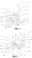
- the apparatus 1 comprises a brewing unit 2 which in turn comprises a first member 3 and a second member 4.
- the first member 3 is movable relative to the second member 4 between an operating position and a home position.
- the second member 4 is fixed and stationary relative to the supporting structure 11, whilst the first member 3 is movable relative to the supporting structure 11.
- the first member 3 and the second member 4 may both be movable relative to the supporting structure 11.
- the second member 4 has a housing 41 which is configured to house the containment body 91 of the capsule 9, whilst the first member 3 is a member for closing the housing 41 and in use faces towards the top lid 95 of the capsule 9.
- the first member 3 and the second member 4 are coupled to one another, thereby forming a brewing chamber in which, in use, the capsule 9 is contained.
- the brewing unit 2 is closed and the beverage can be made.
- the first member 3 and the second member 4 are spaced apart from each other and thereby allow, in use, insertion of the capsule 9 between the first member 3 and the second member 4 (before making the beverage), or removal of the capsule 9 from the brewing unit 2 (after the beverage has been made).
- the brewing unit 2 is open.
- the first member 3 is slidably mounted relative to the supporting structure 11 along a line of movement between the operating position and the home position, and vice versa between the home position and the operating position.
- the line of movement is represented by a straight line labelled with the reference number 200.
- the brewing unit 2 is of the type extending horizontally, that is to say, in which the line of movement of the first member 3 is a substantially horizontal straight line during normal use of the apparatus 1.
- insertion of the capsule 9 occurs from the top, through a window or insertion opening made in the casing (not shown) of the apparatus 1, and the capsule 9 has a central axis which is substantially horizontal (that is to say, the perimetric flange 92 is in a substantially vertical plane, orthogonal to the line of movement 200).
- the movement of the first member 3 is manually driven by a user by means of a lever or a handle 17, which pivots at the supporting structure 11 and acts on a toggle joint 18.
- the movement is motor-driven and may even be automated.
- the aspects relative to the movement of the members of the brewing unit 2 are already known in themselves to experts in the field and are not described in further detail.
- the second member 4 of the brewing unit 2 has the housing 41 for housing the containment body 91 of the capsule 9; this housing 41 has an opening 411 and a concavity which both face towards the first member 3 of the brewing unit 2.
- the housing 41 is shaped in such a way that the capsule 9 is inserted in it during the movement of the first member 3 from the home position to the operating position, as will be made clearer below.
- the perimetric flange 92 is enclosed between the first member 3 and the second member 4.
- the housing 41 is shaped in such a way that it substantially has the same shape as the containment body 91 of the capsule 9, that is to say, the housing 41 mostly follows the shape of the containment body 91; that allows to obtain an improved coupling between the second member 4 and the capsule 9 when the latter is inserted in the housing 41.
- the entire containment body 91 of the capsule 9 can be housed in the housing 41.
- only a portion of the containment body 91 is housed in the housing 41; for example this may be the case in which the perimetric flange 92 is in a position interposed between the top edge 911 and the bottom edge 912 of the containment body 91, rather than at the top edge 911.
- the apparatus 1 also comprises means for piercing the capsule and means for making the beverage.
- the first member 3 comprises a first piercer 39 intended to pierce the top lid 95 of the capsule 9 to create a water infeed opening;
- the second member 4 comprises, on the bottom of the housing 41, a second piercer 49 intended to pierce the bottom wall 94 of the capsule 9 to create a beverage outfeed opening.
- the beverage making means comprise for example: a water tank; a pump; a boiler; pipes for feeding pressurised heated water to the capsule 9 through the infeed opening in the top lid 95; pipes for transferring the beverage coming from the outfeed opening in the bottom wall 94 to a dispenser 19, from which the beverage is dispensed to a cup below or to another container. All of these means can be made in the known way and do not require a detailed description herein.
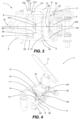
- the brewing unit 2 comprises at least one retaining element 5 and at least one ejector 6, which are parts separate from each other and are movable one relative to the other.
- the brewing unit 2 comprises two retaining elements 5, positioned on opposite flanks of the brewing unit 2 and symmetrically relative to a longitudinal plane thereof (that is to say, relative to a vertical plane which contains a central axis corresponding to the line of movement 200 shown in Figure 3 ).
- the brewing unit 2 comprises two ejectors 6, also positioned on opposite flanks of the brewing unit 2 and symmetrically relative to the longitudinal plane.
- the retaining element 5 is configured to receive the perimetric flange 92 of the capsule 9, when the first member 3 is in the home position and the capsule 9 is inserted between the first member 3 and the second member 4 of the brewing unit 2, and to retain that perimetric flange 92 of the capsule 9 during the movement of the first member 3 from the home position to the operating position, that is to say, during closing of the brewing unit 2.
- the retaining element 5 has a function of preventing the capsule 9 inserted in the open brewing unit 2 from being able to fall any further downwards or in any case from being able to be positioned in an incorrect way preventing its subsequent positioning in the housing 41 of the second member 4.
- the retaining element 5 acts at least until the degree of insertion of the containment body 91 of the capsule 9 in the housing 41 makes its action superfluous.
- the retaining element 5 is slidably mounted relative to the supporting structure 11 and is movable between a receiving position, in which the retaining element 5 is positioned to receive the perimetric flange 92 of the capsule 9, and a disengaging position, in which the retaining element 5 is disengaged from the perimetric flange 92 of the capsule 9.
- a receiving position in which the retaining element 5 is positioned to receive the perimetric flange 92 of the capsule 9
- a disengaging position in which the retaining element 5 is disengaged from the perimetric flange 92 of the capsule 9.
- the movement of the retaining element 5 from the receiving position to the disengaging position comprises a first stretch and a second stretch; the first stretch is parallel to the line of movement 200 of the first member 3, whilst the second stretch is divergent from the line of movement 200. In this way, in the second stretch the retaining element 5 is shifted transversally to the line of movement 200 and, in use, is moved away from the perimetric flange 92 of the capsule 9.
- the ejector 6 is configured to eject the capsule 9 from the housing 41 of the second member 4 during the movement of the first member 3 from the operating position to the home position, that is to say, during opening of the brewing unit 2.
- the ejector 6 is also slidably mounted relative to the supporting structure 11.
- the ejector 6 is movable relative to the second member 4, parallel to the line of movement 200 of the first member 3, between an extracted position and a retracted position.
- the ejector 6 comprises a thrust portion 61 which is configured to push the perimetric flange 92 of the capsule 9 away from the perimetric edge 412 of the opening 411 of the housing 41, during the shifting from the retracted position to the extracted position.
- the ejector 6 in the retracted position the ejector 6 does not interfere with the position of the capsule 9 in the housing 41 and therefore the capsule 9 can be enclosed in the brewing chamber formed by the closed brewing unit 2; in the extracted position the thrust portion 61 of the ejector 6 projects from the second member 4 towards the first member 3. Shifting from the retracted position to the extracted position, the ejector 6 forces the capsule 9 out of the housing 41 and therefore extracts (or ejects) it from the housing 41 itself, until the capsule 9 is free to fall downwards due to gravity.
- the retaining element 5 and the ejector 6 operate in an alternating way: during closing of the brewing unit 2, the capsule 9 is retained by the retaining element 5 and its positioning in the housing 41 is not disturbed by the ejector 6; during opening of the brewing unit 2, the capsule 9 is not retained by the retaining element 5 and is subjected to the action of the ejector 6.
- This invention relates to the implementation of a mode for coordinated movement of the retaining element 5 and of the ejector 6 in order to achieve that.
- the movement of the retaining element 5, between the receiving position and the disengaging position and vice versa, and the movement of the ejector 6, between the extracted position and the retracted position and vice versa, are caused by the movement of the first member 3 which mechanically operates in conjunction with both the retaining element 5 and the ejector 6, thereby controlling their positions.
- the movement of the first member 3 from the home position to the operating position causes the movement of the retaining element 5 from the receiving position to the disengaging position and the movement of the ejector 6 from the extracted position to the retracted position; moreover, the movement of the first member 3 from the operating position to the home position, that is to say, opening of the brewing unit 2, causes the movement of the retaining element 5 from the disengaging position to the receiving position and the movement of the ejector 6 from the retracted position to the extracted position.
- the retaining element 5 and the ejector 6 will be described in detail below, together with other significant aspects of the apparatus 1.
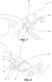
- the apparatus 1 comprises a guide which mechanically operates in conjunction with the retaining element 5.
- the guide extends along a flank of the brewing unit 2 and is made in the supporting structure 11 (in particular in a wall 13) of the apparatus 1.
- the guide comprises (or is constituted of) a lane 12 which has a first guiding stretch 121 and a second guiding stretch 122: the first guiding stretch 121 is parallel to the line of movement 200 of the first member 3, whilst the second guiding stretch 122 is divergent from the line of movement 200 of the first member 3.
- the second guiding stretch 122 and the first guiding stretch 121 are respective pieces or stretches of the lane 12, are one after the other and are engaged sequentially by the retaining element 5.
- the retaining element 5 comprises a follower 55 which engages with the lane 12 and is movable along the lane 12. Since the follower 55 moves along both of the pieces 121, 122, in the embodiment illustrated the mechanical operation of the retaining element 5 in conjunction with the guide is not limited to the divergent second stretch of its movement but also relates to the first stretch.
- the movement of the retaining element 5 may comprise further stretches which are interposed between the first stretch and the second stretch and/or which are placed upstream of the first stretch and/or which are placed downstream of the second stretch.
- the first member 3 comprises a first thrust element 31 and a second thrust element 32 which are movable together with a main body 33 of the first member 3.
- the first thrust element 31 and the second thrust element 32 are made in one piece with the main body 33.
- the first thrust element 31 is a portion of an edge of the main body 33
- the second thrust element 32 is a tooth which projects from the first thrust element 31 or directly from the main body 33.
- the first thrust element 31 makes contact with and pushes the retaining element 5 during the movement of the first member 3 from the home position to the operating position and is disengaged from the retaining element 5 when the latter reaches the disengaging position.
- the second thrust element 32 makes contact with and pushes the retaining element 5 during the movement of the first member 3 from the operating position to the home position.
- the second thrust element 32 makes contact with a raised portion 54 of the retaining element 5.
- the retaining element 5 comprises a receiving portion 51 which defines a seat 514 for receiving the perimetric flange 92 of the capsule 9; the receiving portion 51 has an elongate shape and the seat 514 is a furrow which extends in it in such a way as to accommodate an angular sector of the perimetric flange 92.
- the receiving portion 51 has a base wall 511 and two sides, respectively a first side 512 and a second side 513, which are substantially parallel to each other and extend starting from the base wall 511.
- the receiving portion 51 has a U-shaped or C-shaped cross-section, in such a way that the seat 514 is laterally delimited by two flanks, respectively a first flank 516 defined by the first side 512 and a second flank 517 defined by the second side 513, and by a bottom 515, which joins the first flank 516 and the second flank 517 and which is defined by the base wall 511.
- the base wall 511 of the receiving portion 51 defines a bottom 515 of the seat 514.
- the base wall 511 is angled towards the inside of the seat 514, following the curved profile of the perimetric flange 92, at a lower part of the receiving portion 51, so that the perimetric flange 92 leans against the angled part.
- the shape of the seat 514 which in fact is long and narrow, holds the capsule 9 with its central axis substantially horizontal, preventing the capsule 9 from being tilted downwards, and the angled lower part of the base wall 511 prevents the capsule 9 from falling downwards.
- capsule 9 retaining derives from the combined action of the two retaining elements 5.
- the receiving portion 51 may be made in a different way in order to achieve the same aim, even based on what is already present in the prior art.
- the retaining element 5 also comprises a pin 52 and an arm 53 which connects the pin 52 to the receiving portion 51.
- the pin 52 defines an axis of rotation 520 about which the retaining element 5 is rotatable.
- the first stretch of the movement parallel to the line of movement 200 of the first member 3, the rotation of the retaining element 5 about the axis of rotation 520 defined by the pin 52 is prevented by the guide and therefore the retaining element 5 only translates;
- the second stretch of the movement which is divergent from the line of movement 200 of the first member 3, the rotation of the retaining element 5 about the axis of rotation 520 is allowed and therefore the movement of the retaining element 5 in the second stretch is a combination of a translating movement, parallel to the line of movement 200 of the first member 3, and of a rotary movement, about the axis of rotation 520.
- the result of that rotary-translating movement is that the receiving portion 51 is shifted transversally to the line of movement 200.
- the pin 52 may be positioned at the raised portion 54, which is intended to make contact with the second thrust element 32 of the first member 3, is raised relative to the arm 53 and is located near the pin 52, which projects relative to the raised portion 54.
- the pin 52 and the raised portion 54 are interposed between a flank of the main body 33 of the first member 3 and a surface 1211 of the lane 12 ( Figure 3 ). Said surface 1211 extends parallel to the line of movement 200 and faces towards the inside of the apparatus 1, in particular facing a flank of the main body 33.
- the pin 52 and the raised portion 54 are present, whilst at a second end of the arm 53 the receiving portion 51 and the follower 55 are present.
- the follower 55 projects from the arm 53 and specifically is a wing which, in a plan view ( Figure 15 ), is angled relative to the arm 53 and extends from the opposite side relative to the receiving portion 51.
- the follower 55 has an outer face 551 which, when the follower 55 is in the first guiding stretch 121, is against said surface 1211 of the lane 12 ( Figure 3 ) and that prevents rotation of the retaining element 5 towards the outside; the follower 55 also has a tip 552 which, at the end of the first guiding stretch 121, makes contact against an angled surface 1221 of the second guiding stretch 122, which diverts the follower into the second guiding stretch 122 and forces the retaining element 5 to rotate towards the outside.
- the follower 55 engages with the lane 12 in the second guiding stretch 122, the follower 55 makes the retaining element 5 rotate about the axis of rotation 520 defined by the pin 52 and in that way shifts it transversally.
- the arm 53 has a face 531 which is substantially facing towards the inside of the apparatus 1 and which, when the retaining element 5 is in the receiving position, is angled relative to the line of movement 200.
- the face 531 is configured to make contact with the first thrust element 31 of the first member 3 when the first member 3 is moved from the home position to the operating position and, thanks to the angle of the face 531 and the operation in conjunction with the first guiding stretch 121 which prevents the rotation of the retaining element 5, the resulting force pushes the retaining element 5 parallel to the line of movement 200.
- the contact between the first face 531 and the first thrust element 31 occurs at a corner 311 of the first thrust element 31.
- the retaining element 5 engages with the second guiding stretch 122, it can rotate towards the outside about the axis of rotation 520, until (in the disengaging position) the face 531 is parallel to the line of movement 200.
- the first thrust element 31 can no longer push on the face 531 and therefore, with the further forward movement of the first member 3, the corner 311 slides along the face 531 itself.
- the ejector 6 As regards the ejector 6, as already said it is movable between the extracted position and the retracted position, and vice versa.
- the thrust portion 61 of the ejector 6 In the extracted position ( Figures 1 to 3 ), the thrust portion 61 of the ejector 6 is positioned between the retaining element 5 and the second member 4; in the retracted position ( Figures 7 to 9 ), the thrust portion 61 is contained between the first member 3 and the second member 4, whilst the receiving portion 51 of the retaining element 5 is located at a side and outside relative to the thrust portion 61.
- the thrust portion 61 of the ejector 6 forms a part of the perimetric edge 412 of the opening 411 of the housing 41 of the second member 4.
- the perimetric edge 412 made in the second member 4 has an interrupted stretch which forms a cavity shaped to match the thrust portion 61, which occupies the cavity when the ejector 6 is in the retracted position.
- the thrust portion 61 and the second member 4 jointly define the perimetric edge 412 which, in use, is in contact with the perimetric flange 92 of the capsule 9.
- the perimetric edge 412 When the ejector 6 is in the extracted position, the perimetric edge 412 is interrupted and the thrust portion 61 is spaced apart from the interrupted perimetric edge 412: the thrust portion 61 is interposed between the first member 3 and the second member 4 and is spaced apart from both.
- the perimetric edge 412 shaped in this way combines a continuity of support for the perimetric flange 92 of the capsule 9 with a simplicity of actuation of the ejector 6 during opening of the brewing unit 2.
- the thrust portion 61 is in contact with the perimetric flange 92 of the capsule 9 even when the brewing unit 2 is closed and therefore the movement of the ejector 6 immediately causes the movement of the capsule 9.
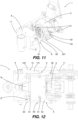
- the movement of the ejector 6, at least in the movement towards the extracted position, is caused by the interaction between a projecting tooth (which is part of one of either the first member 3 or the ejector 6) and a respective contact element (which is part of the other of either the first member 3 or the ejector 6).
- the first member 3 comprises the projecting tooth, labelled with the reference number 34
- the ejector 6 comprises the contact element (labelled with the reference number 622) for the projecting tooth 34.
- the arrangement of the projecting tooth and of the contact element may be inverted (that is to say, the ejector comprises the projecting tooth and the first member comprises the contact element).
- the projecting tooth 34 When the first member 3 is in the operating position, the projecting tooth 34 is spaced apart from the contact element 622. During the movement of the first member 3 from the operating position to the home position, that is to say, during opening of the brewing unit 2, the projecting tooth 34 makes contact with the contact element 622. The contact between the projecting tooth 34 and the contact element 622 causes a mechanical constraint (due to contrast of parts) between the ejector 6 and the first member 3, so that the ejector 6 is dragged towards the retracted position by the first member 3 moving towards the home position.
- the contact element 622 is a stop for the projecting tooth 34 and is part of a slot 621 or of a track which extends parallel to the line of movement 200 of the first member 3. The projecting tooth 34 is received in the slot 621 or in the track and can run in it, parallel to the line of movement 200.
- the ejector 6 comprises an elongate portion 62 which extends parallel to the line of movement 200 and defines the slot 621 inside which the projecting tooth 34 of the first member 3 slides.
- the contact element 622 is one end of the slot 621, the end which is furthest from the thrust portion 61.
- the slot 621 is an elongate opening.
- the thrust portion 61 projects from the elongate portion 62 towards the inside of the brewing unit 2, preferably perpendicularly to the line of movement 200.
- the elongate portion 62 and the thrust portion 61 are made in one piece.
- the second member 4 has, on its outer surface, a groove 42 in which the elongate portion 62 is slidably mounted. That groove 42 acts as a guide for the movement of the ejector 6 and constrains it to perform a translation along the line of movement 200.
- the groove 42 may be substituted with a through hole in the second member 4 or may be made in the supporting structure 11. Other embodiments which allow sliding of the elongate portion 62 are obviously possible.
- the elongate portion 62 has a projection or a small tooth 625 which projects externally.
- the small tooth 625 creates a weak constraint with the supporting structure 11 relative to which the ejector 6 slides. That weak constraint is sufficient to prevent a friction force between the projecting tooth 34 and the slot 621 from being able to move the ejector 6 in an initial step of opening of the brewing unit 2, but is easily overcome when the projecting tooth 34 makes contact against the contact element 622 (that is to say, the stop of the slot 621) and pulls the ejector 6.
- the small tooth 625 operates in conjunction with an opposite small tooth in the supporting structure 11 which is jumped over, during opening and closing of the brewing unit 2, thanks to a small vertical play of the elongate portion 62 or to a limited elastic deformability of the parts.
- the movement of the ejector 6 occurs with a calibrated delay relative to the movement of the first member 3 and relative to the movement of the retaining element 5, completely avoiding the risk that the capsule 9 may be extracted too early and may accidentally be hooked by the retaining element 5.
- the presence of the small tooth 625 is a precaution which is not strictly necessary.
- the resistance opposed by the capsule 9 in the housing 41 is usually much greater than the friction between the projecting tooth 34 and the slot 621, therefore it is the capsule 9 which prevents a too early movement of the ejector 6.
- the movement of the ejector 6 from the extracted position to the retracted position in one embodiment it is caused by the interaction between the projecting tooth 34 and a second contact element, for example the other end 623 of the slot 621 (the end which is closest to the thrust portion 61).
- it is caused by the thrust which the thrust portion 61 initially receives from the receiving portion 51 of the retaining element 5 (with which it makes contact) and then from the perimetric flange 92 of the capsule 9; in this case, the first member 3 causes the movement of the ejector 6 towards the retracted position by acting by means of the retaining element 5 and by means of the capsule 9, not acting directly on the ejector 6.
- the retaining element 5 and the ejector 6 are positioned on a same flank of the brewing unit 2.
- the apparatus 1 comprises two retaining elements 5 and two ejectors 6, each made according to what is described above.
- the first retaining element 5 and the second retaining element 5 are positioned on opposite flanks (right-hand flank and left-hand flank) of the brewing unit 2 and are positioned symmetrically relative to the longitudinal plane of the brewing unit 2; although physically independent of each other, they are moved simultaneously and in a coordinated way.
- the same also applies for the first ejector 6 and for the second ejector 6. That symmetrical arrangement is useful for obtaining more balanced and more reliable operation, compared with the presence of only one retaining element 5 and only one ejector 6.
- an operating cycle of the apparatus 1 is as follows:
- the first member 3, the retaining element 5 and the ejector 6 are constrained to the supporting structure 11 (directly or indirectly) independently of each other and they are also movable relative to the supporting structure 11 with only one degree of freedom.
- the movement path - relative to the supporting structure 11 - between their limit positions that is to say, the position with brewing unit 2 open and the position with brewing unit 2 closed.
- the retaining element 5 and the ejector 6 are physically interposed between the first member 3 and the second member 4; the first member 3 mechanically operates in conjunction (thanks to respective parts which make contact with each other) with the retaining element 5 and with the ejector 6 and cases their movements. Consequently, during use of the apparatus 1 the movements and the positions required for those components are obtained in a precise way and without possibility of error, since the retaining element 5 and the ejector 6 do not have degrees of freedom which allow their accidental deviation from what has been set. There is no need for other elements (such as springs) which force the components towards predetermined positions.
- this invention is useful for supplying an apparatus which is simple and mechanically reliable.
- the retaining element 5 and the ejector 6 are each a single part which is constrained to the supporting structure 11 and which is moved by the movable member of the brewing unit, without requiring the movement of other parts.
- this invention is useful for supplying an apparatus for making a beverage comprising both a retaining element 5 and an ejector 6, with less complexity than prior art apparatuses.
Landscapes
- Engineering & Computer Science (AREA)
- Mechanical Engineering (AREA)
- Food Science & Technology (AREA)
- Apparatus For Making Beverages (AREA)
- Non-Alcoholic Beverages (AREA)
Applications Claiming Priority (2)
| Application Number | Priority Date | Filing Date | Title |
|---|---|---|---|
| IT102021000012077A IT202100012077A1 (it) | 2021-05-11 | 2021-05-11 | Apparecchiatura per la preparazione di una bevanda tramite infusione di una sostanza alimentare contenuta in una capsula |
| PCT/IB2022/054393 WO2022238930A1 (en) | 2021-05-11 | 2022-05-11 | Apparatus for making a beverage by brewing a food substance contained in a capsule |
Publications (3)
| Publication Number | Publication Date |
|---|---|
| EP4337071A1 EP4337071A1 (en) | 2024-03-20 |
| EP4337071B1 true EP4337071B1 (en) | 2025-05-07 |
| EP4337071C0 EP4337071C0 (en) | 2025-05-07 |
Family
ID=77317218
Family Applications (1)
| Application Number | Title | Priority Date | Filing Date |
|---|---|---|---|
| EP22726523.8A Active EP4337071B1 (en) | 2021-05-11 | 2022-05-11 | Apparatus for making a beverage by brewing a food substance contained in a capsule |
Country Status (10)
| Country | Link |
|---|---|
| US (1) | US20240225345A1 (pl) |
| EP (1) | EP4337071B1 (pl) |
| AU (1) | AU2022204735A1 (pl) |
| BR (1) | BR112023023556A2 (pl) |
| ES (1) | ES3033063T3 (pl) |
| HU (1) | HUE072335T2 (pl) |
| IL (1) | IL308482A (pl) |
| IT (1) | IT202100012077A1 (pl) |
| PL (1) | PL4337071T3 (pl) |
| WO (1) | WO2022238930A1 (pl) |
Family Cites Families (5)
| Publication number | Priority date | Publication date | Assignee | Title |
|---|---|---|---|---|
| CN100544647C (zh) * | 2007-06-15 | 2009-09-30 | 宁波三A集团电器有限公司 | 咖啡机中咖啡包的自动脱落机构 |
| WO2010032271A1 (en) * | 2008-09-18 | 2010-03-25 | Saeco Ipr Limited | Infusion device for coffee machines and the like |
| PT105712A (pt) * | 2011-05-19 | 2012-11-19 | Novadelta Com E Ind De Cafes S A | Dispositivo de extracção de cápsulas, processo de operação deste e máquina incluindo o referido dispositivo |
| ITVR20130195A1 (it) | 2013-08-09 | 2015-02-10 | Caffita System Spa | Gruppo orizzontale per la preparazione di bevande utilizzando capsule contenenti sostanze alimentari in polvere |
| IT201800004761A1 (it) | 2018-04-20 | 2019-10-20 | Apparecchiatura per la preparazione di una bevanda utilizzando una capsula o una cialda contenente una sostanza alimentare |
-
2021
- 2021-05-11 IT IT102021000012077A patent/IT202100012077A1/it unknown
-
2022
- 2022-05-11 HU HUE22726523A patent/HUE072335T2/hu unknown
- 2022-05-11 ES ES22726523T patent/ES3033063T3/es active Active
- 2022-05-11 BR BR112023023556A patent/BR112023023556A2/pt unknown
- 2022-05-11 EP EP22726523.8A patent/EP4337071B1/en active Active
- 2022-05-11 PL PL22726523.8T patent/PL4337071T3/pl unknown
- 2022-05-11 IL IL308482A patent/IL308482A/en unknown
- 2022-05-11 US US18/559,967 patent/US20240225345A1/en active Pending
- 2022-05-11 WO PCT/IB2022/054393 patent/WO2022238930A1/en not_active Ceased
- 2022-05-11 AU AU2022204735A patent/AU2022204735A1/en active Pending
Also Published As
| Publication number | Publication date |
|---|---|
| IT202100012077A1 (it) | 2022-11-11 |
| HUE072335T2 (hu) | 2025-11-28 |
| BR112023023556A2 (pt) | 2024-02-06 |
| ES3033063T3 (en) | 2025-07-30 |
| EP4337071C0 (en) | 2025-05-07 |
| WO2022238930A1 (en) | 2022-11-17 |
| AU2022204735A1 (en) | 2022-12-01 |
| IL308482A (en) | 2024-01-01 |
| PL4337071T3 (pl) | 2025-08-04 |
| EP4337071A1 (en) | 2024-03-20 |
| US20240225345A1 (en) | 2024-07-11 |
Similar Documents
| Publication | Publication Date | Title |
|---|---|---|
| TWI576075B (zh) | 用於準備飲料的裝置及相關程序 | |
| JP4332178B2 (ja) | カプセル抽出装置 | |
| US8567304B2 (en) | Beverage preparation machines | |
| US20100206177A1 (en) | Assembly comprising an appliance and a disposable capsule for producing a brewed drink, and capsule for such an assembly | |
| EP2717749B1 (en) | Delivery assembly for machines for preparing liquid products via cartridges | |
| CN103796560A (zh) | 具有锁定件的枢转闭合的饮料配料保持器 | |
| PT2131704E (pt) | Dispositivo para preparar uma bebida líquida a partir de uma cápsula | |
| EP4337071B1 (en) | Apparatus for making a beverage by brewing a food substance contained in a capsule | |
| EP4391872B1 (en) | Apparatus for making a beverage by infusion of a food substance | |
| US9468329B2 (en) | Tea brewing assembly | |
| EP4391874B1 (en) | Apparatus for making a beverage by infusion of a food substance | |
| HK1145078B (en) | Improvements in or relating to beverage preparation machines | |
| CN103826508A (zh) | 具有穿刺件的枢转闭合的饮料配料保持器 | |
| HK1224534A1 (en) | Horizontal unit for making beverages using capsules containing powdered food substances |
Legal Events
| Date | Code | Title | Description |
|---|---|---|---|
| STAA | Information on the status of an ep patent application or granted ep patent |
Free format text: STATUS: UNKNOWN |
|
| STAA | Information on the status of an ep patent application or granted ep patent |
Free format text: STATUS: THE INTERNATIONAL PUBLICATION HAS BEEN MADE |
|
| PUAI | Public reference made under article 153(3) epc to a published international application that has entered the european phase |
Free format text: ORIGINAL CODE: 0009012 |
|
| STAA | Information on the status of an ep patent application or granted ep patent |
Free format text: STATUS: REQUEST FOR EXAMINATION WAS MADE |
|
| 17P | Request for examination filed |
Effective date: 20231116 |
|
| AK | Designated contracting states |
Kind code of ref document: A1 Designated state(s): AL AT BE BG CH CY CZ DE DK EE ES FI FR GB GR HR HU IE IS IT LI LT LU LV MC MK MT NL NO PL PT RO RS SE SI SK SM TR |
|
| DAV | Request for validation of the european patent (deleted) | ||
| DAX | Request for extension of the european patent (deleted) | ||
| GRAP | Despatch of communication of intention to grant a patent |
Free format text: ORIGINAL CODE: EPIDOSNIGR1 |
|
| STAA | Information on the status of an ep patent application or granted ep patent |
Free format text: STATUS: GRANT OF PATENT IS INTENDED |
|
| INTG | Intention to grant announced |
Effective date: 20241204 |
|
| GRAS | Grant fee paid |
Free format text: ORIGINAL CODE: EPIDOSNIGR3 |
|
| GRAA | (expected) grant |
Free format text: ORIGINAL CODE: 0009210 |
|
| STAA | Information on the status of an ep patent application or granted ep patent |
Free format text: STATUS: THE PATENT HAS BEEN GRANTED |
|
| AK | Designated contracting states |
Kind code of ref document: B1 Designated state(s): AL AT BE BG CH CY CZ DE DK EE ES FI FR GB GR HR HU IE IS IT LI LT LU LV MC MK MT NL NO PL PT RO RS SE SI SK SM TR |
|
| REG | Reference to a national code |
Ref country code: GB Ref legal event code: FG4D |
|
| REG | Reference to a national code |
Ref country code: CH Ref legal event code: EP |
|
| REG | Reference to a national code |
Ref country code: DE Ref legal event code: R096 Ref document number: 602022014344 Country of ref document: DE |
|
| REG | Reference to a national code |
Ref country code: IE Ref legal event code: FG4D |
|
| U01 | Request for unitary effect filed |
Effective date: 20250604 |
|
| U07 | Unitary effect registered |
Designated state(s): AT BE BG DE DK EE FI FR IT LT LU LV MT NL PT RO SE SI Effective date: 20250611 |
|
| PGFP | Annual fee paid to national office [announced via postgrant information from national office to epo] |
Ref country code: ES Payment date: 20250612 Year of fee payment: 4 |
|
| PGFP | Annual fee paid to national office [announced via postgrant information from national office to epo] |
Ref country code: CH Payment date: 20250601 Year of fee payment: 4 |
|
| REG | Reference to a national code |
Ref country code: ES Ref legal event code: FG2A Ref document number: 3033063 Country of ref document: ES Kind code of ref document: T3 Effective date: 20250730 |
|
| U20 | Renewal fee for the european patent with unitary effect paid |
Year of fee payment: 4 Effective date: 20250624 |
|
| PG25 | Lapsed in a contracting state [announced via postgrant information from national office to epo] |
Ref country code: NO Free format text: LAPSE BECAUSE OF FAILURE TO SUBMIT A TRANSLATION OF THE DESCRIPTION OR TO PAY THE FEE WITHIN THE PRESCRIBED TIME-LIMIT Effective date: 20250807 Ref country code: GR Free format text: LAPSE BECAUSE OF FAILURE TO SUBMIT A TRANSLATION OF THE DESCRIPTION OR TO PAY THE FEE WITHIN THE PRESCRIBED TIME-LIMIT Effective date: 20250808 |
|
| PGFP | Annual fee paid to national office [announced via postgrant information from national office to epo] |
Ref country code: PL Payment date: 20250624 Year of fee payment: 4 |
|
| PGFP | Annual fee paid to national office [announced via postgrant information from national office to epo] |
Ref country code: HU Payment date: 20250513 Year of fee payment: 4 |
|
| PG25 | Lapsed in a contracting state [announced via postgrant information from national office to epo] |
Ref country code: HR Free format text: LAPSE BECAUSE OF FAILURE TO SUBMIT A TRANSLATION OF THE DESCRIPTION OR TO PAY THE FEE WITHIN THE PRESCRIBED TIME-LIMIT Effective date: 20250507 |
|
| PG25 | Lapsed in a contracting state [announced via postgrant information from national office to epo] |
Ref country code: RS Free format text: LAPSE BECAUSE OF FAILURE TO SUBMIT A TRANSLATION OF THE DESCRIPTION OR TO PAY THE FEE WITHIN THE PRESCRIBED TIME-LIMIT Effective date: 20250807 |
|
| PG25 | Lapsed in a contracting state [announced via postgrant information from national office to epo] |
Ref country code: IS Free format text: LAPSE BECAUSE OF FAILURE TO SUBMIT A TRANSLATION OF THE DESCRIPTION OR TO PAY THE FEE WITHIN THE PRESCRIBED TIME-LIMIT Effective date: 20250907 |
|
| REG | Reference to a national code |
Ref country code: HU Ref legal event code: AG4A Ref document number: E072335 Country of ref document: HU |
|
| PG25 | Lapsed in a contracting state [announced via postgrant information from national office to epo] |
Ref country code: SM Free format text: LAPSE BECAUSE OF FAILURE TO SUBMIT A TRANSLATION OF THE DESCRIPTION OR TO PAY THE FEE WITHIN THE PRESCRIBED TIME-LIMIT Effective date: 20250507 |
|
| PG25 | Lapsed in a contracting state [announced via postgrant information from national office to epo] |
Ref country code: CZ Free format text: LAPSE BECAUSE OF FAILURE TO SUBMIT A TRANSLATION OF THE DESCRIPTION OR TO PAY THE FEE WITHIN THE PRESCRIBED TIME-LIMIT Effective date: 20250507 |
|
| PG25 | Lapsed in a contracting state [announced via postgrant information from national office to epo] |
Ref country code: SK Free format text: LAPSE BECAUSE OF FAILURE TO SUBMIT A TRANSLATION OF THE DESCRIPTION OR TO PAY THE FEE WITHIN THE PRESCRIBED TIME-LIMIT Effective date: 20250507 |
|
| PG25 | Lapsed in a contracting state [announced via postgrant information from national office to epo] |
Ref country code: MC Free format text: LAPSE BECAUSE OF FAILURE TO SUBMIT A TRANSLATION OF THE DESCRIPTION OR TO PAY THE FEE WITHIN THE PRESCRIBED TIME-LIMIT Effective date: 20250507 |
|
| PLBE | No opposition filed within time limit |
Free format text: ORIGINAL CODE: 0009261 |
|
| STAA | Information on the status of an ep patent application or granted ep patent |
Free format text: STATUS: NO OPPOSITION FILED WITHIN TIME LIMIT |
|
| REG | Reference to a national code |
Ref country code: CH Ref legal event code: L10 Free format text: ST27 STATUS EVENT CODE: U-0-0-L10-L00 (AS PROVIDED BY THE NATIONAL OFFICE) Effective date: 20260318 |
|
| PG25 | Lapsed in a contracting state [announced via postgrant information from national office to epo] |
Ref country code: IE Free format text: LAPSE BECAUSE OF NON-PAYMENT OF DUE FEES Effective date: 20250511 |
|
| 26N | No opposition filed |
Effective date: 20260210 |