EP4336532A1 - Kontaktor - Google Patents
Kontaktor Download PDFInfo
- Publication number
- EP4336532A1 EP4336532A1 EP23195342.3A EP23195342A EP4336532A1 EP 4336532 A1 EP4336532 A1 EP 4336532A1 EP 23195342 A EP23195342 A EP 23195342A EP 4336532 A1 EP4336532 A1 EP 4336532A1
- Authority
- EP
- European Patent Office
- Prior art keywords
- static
- magnetic
- insulation
- terminal
- bracket
- Prior art date
- Legal status (The legal status is an assumption and is not a legal conclusion. Google has not performed a legal analysis and makes no representation as to the accuracy of the status listed.)
- Pending
Links
Images


Classifications
-
- H—ELECTRICITY
- H01—ELECTRIC ELEMENTS
- H01H—ELECTRIC SWITCHES; RELAYS; SELECTORS; EMERGENCY PROTECTIVE DEVICES
- H01H50/00—Details of electromagnetic relays
- H01H50/02—Bases; Casings; Covers
- H01H50/04—Mounting complete relay or separate parts of relay on a base or inside a case
- H01H50/041—Details concerning assembly of relays
- H01H50/045—Details particular to contactors
-
- H—ELECTRICITY
- H01—ELECTRIC ELEMENTS
- H01H—ELECTRIC SWITCHES; RELAYS; SELECTORS; EMERGENCY PROTECTIVE DEVICES
- H01H51/00—Electromagnetic relays
- H01H51/02—Non-polarised relays
- H01H51/04—Non-polarised relays with single armature; with single set of ganged armatures
- H01H51/06—Armature is movable between two limit positions of rest and is moved in one direction due to energisation of an electromagnet and after the electromagnet is de-energised is returned by energy stored during the movement in the first direction, e.g. by using a spring, by using a permanent magnet, by gravity
- H01H51/065—Relays having a pair of normally open contacts rigidly fixed to a magnetic core movable along the axis of a solenoid, e.g. relays for starting automobiles
-
- H—ELECTRICITY
- H01—ELECTRIC ELEMENTS
- H01H—ELECTRIC SWITCHES; RELAYS; SELECTORS; EMERGENCY PROTECTIVE DEVICES
- H01H1/00—Contacts
- H01H1/50—Means for increasing contact pressure, preventing vibration of contacts, holding contacts together after engagement, or biasing contacts to the open position
- H01H1/54—Means for increasing contact pressure, preventing vibration of contacts, holding contacts together after engagement, or biasing contacts to the open position by magnetic force
-
- H—ELECTRICITY
- H01—ELECTRIC ELEMENTS
- H01H—ELECTRIC SWITCHES; RELAYS; SELECTORS; EMERGENCY PROTECTIVE DEVICES
- H01H50/00—Details of electromagnetic relays
- H01H50/16—Magnetic circuit arrangements
- H01H50/18—Movable parts of magnetic circuits, e.g. armature
- H01H50/20—Movable parts of magnetic circuits, e.g. armature movable inside coil and substantially lengthwise with respect to axis thereof; movable coaxially with respect to coil
- H01H50/22—Movable parts of magnetic circuits, e.g. armature movable inside coil and substantially lengthwise with respect to axis thereof; movable coaxially with respect to coil wherein the magnetic circuit is substantially closed
-
- H—ELECTRICITY
- H01—ELECTRIC ELEMENTS
- H01H—ELECTRIC SWITCHES; RELAYS; SELECTORS; EMERGENCY PROTECTIVE DEVICES
- H01H50/00—Details of electromagnetic relays
- H01H50/16—Magnetic circuit arrangements
- H01H50/36—Stationary parts of magnetic circuit, e.g. yoke
-
- H—ELECTRICITY
- H01—ELECTRIC ELEMENTS
- H01H—ELECTRIC SWITCHES; RELAYS; SELECTORS; EMERGENCY PROTECTIVE DEVICES
- H01H50/00—Details of electromagnetic relays
- H01H50/16—Magnetic circuit arrangements
- H01H50/36—Stationary parts of magnetic circuit, e.g. yoke
- H01H50/38—Part of main magnetic circuit shaped to suppress arcing between the contacts of the relay
-
- H—ELECTRICITY
- H01—ELECTRIC ELEMENTS
- H01H—ELECTRIC SWITCHES; RELAYS; SELECTORS; EMERGENCY PROTECTIVE DEVICES
- H01H9/00—Details of switching devices, not covered by groups H01H1/00 - H01H7/00
- H01H9/30—Means for extinguishing or preventing arc between current-carrying parts
- H01H9/44—Means for extinguishing or preventing arc between current-carrying parts using blow-out magnet
- H01H9/443—Means for extinguishing or preventing arc between current-carrying parts using blow-out magnet using permanent magnets
-
- H—ELECTRICITY
- H01—ELECTRIC ELEMENTS
- H01H—ELECTRIC SWITCHES; RELAYS; SELECTORS; EMERGENCY PROTECTIVE DEVICES
- H01H50/00—Details of electromagnetic relays
- H01H50/02—Bases; Casings; Covers
- H01H50/04—Mounting complete relay or separate parts of relay on a base or inside a case
- H01H50/041—Details concerning assembly of relays
- H01H2050/046—Assembling parts of a relay by using snap mounting techniques
Definitions
- the present invention relates to a contactor.
- the current carrying capacity of high-voltage DC contactors is average, and their ability to withstand large currents for a short period of time is limited.
- the ability to withstand short circuit current is generally within 2500-5000A, which cannot meet the technical requirements of the future market.
- Some manufacturers have improved the contact structure of contactors to increase the product's ability to withstand short circuit current.
- these types of improved structures often have certain technical defects: although the ability to withstand short-circuit current is improved, the ability of the contactor to cut off current and turn on current both decreases to a certain extent.
- the present invention has been made to overcome or alleviate at least one aspect of the above mentioned disadvantages.
- a contactor comprising of an insulation outer housing; a pair of static terminals which is provided in the insulation outer housing and stationary relative to the insulation outer housing; a movable terminal which is provided in the insulation outer housing and movable between a closed position in contact with the static terminal and an opened position separated from the static terminal; a first magnetic conductor which is fixed to the movable terminal to move synchronously with the movable terminal; a static bracket which is provided in the insulation outer housing and stationary relative to the insulation outer housing; a second magnetic conductor which is movably provided in the static bracket; and an elastic member which is provided between the static bracket and the second magnetic conductor.
- the second magnetic conductor and the static terminal are arranged at the same side of the movable terminal, and the second magnetic conductor is floatable supported in the static bracket by the elastic member.
- the static bracket includes a bottom plate, a side plate and an inner cavity defined by the bottom plate and the side plate, the second magnetic conductor is accommodated in the inner cavity of the static bracket, and the elastic member is compressed between the second magnetic conductor and the bottom plate of the static bracket.
- a guide rib extending in a vertical direction is formed on one of the side plate of the static bracket and the side face of the second magnetic conductor, and a guide groove is formed on the other of the side plate of the static bracket and the side face of the second magnetic conductor; the guide rib is mated with the guide groove to guide the second magnetic conductor to move in the vertical direction relative to the static bracket.
- the contactor further comprises an insulation inner housing which is arranged in the insulation outer housing and has an inner space that serves as an arc extinguishing chamber, the static terminal is fixed to the insulation inner housing and extends into the arc extinguishing chamber, the static bracket is located in the arc extinguishing chamber and is fixed to the insulation inner housing.
- the static bracket further comprises a connecting part which is connected to the upper side of the side plate and extends upwards, a hole is formed in the insulation inner housing, and the connecting part is inserted into the hole of the insulation inner housing to fix the static bracket to the insulation inner housing.
- a barbed protrusion is formed on the connecting part, and the barbed protrusion on the connecting part is in an interference fit with the hole wall of the hole of the insulation inner housing.
- the elastic member and the second magnetic conductor are located in the arc extinguishing chamber and are detachably assembled together.
- the contactor further comprises a pair of magnetic blowing magnets arranged in the arc extinguishing chamber and stationary relative to the static terminal, the static terminal has a contact end for contacting the movable terminal, and the pair of magnetic blowing magnets are respectively adjacent to the contact ends of the pair of static terminals, a magnetic field intensity generated by the magnetic blowing magnet itself at the contact end of the static terminal adjacent to the magnetic blowing magnet is higher than a predetermined magnetic field intensity, in order to extinguish an electric arc between the movable terminal and the static terminal through magnetic blowing.
- the direction of the electromagnetic force applied to the electric arc between the static terminal and the movable terminal by the magnetic field generated by the magnetic blowing magnet itself is horizontal.
- one magnetic blowing magnet is adjacent to the contact end of one static terminal, and the other magnetic blowing magnet is adjacent to the contact end of the other static terminal;
- the direction of the electromagnetic force applied to the electric arc between the one static terminal and the movable terminal by the magnetic field generated by the one magnetic blowing magnet itself is a first horizontal direction;
- the direction of the electromagnetic force applied to the electric arc between the other static terminal and the movable terminal by the magnetic field generated by the other magnetic blowing magnet itself is the first horizontal direction or a second horizontal direction opposite to the first horizontal direction.
- the contactor further comprises an insulation end cap.
- the insulation end cap comprises of a cover plate which is installed on a bottom opening of the insulation inner housing; and a pair of support parts connected to the cover plate and located in the arc extinguishing chamber.
- the pair of magnetic blowing magnets are respectively fixed to the pair of support parts of the insulation end cap.
- a recess is formed on the support part, and the magnetic blowing magnet is embedded in the recess on the support part.
- the contactor further comprises of an insulation base located in the arc extinguishing chamber and supported on the cover plate of the insulation end cap; a support substrate fixed to the insulation base; a contact spring which is compressed between the second magnetic conductor and the support substrate to provide a contact force between the movable terminal and the static terminal; and a limit bracket fixed to the support substrate to limit the movement direction and distance of the movable terminal relative to the support substrate.
- the contactor further comprises a drive shaft.
- An upper end of the drive shaft extends into the arc extinguishing chamber and is fixed to the insulation base, the insulation base electrically isolates the drive shaft from the support substrate.
- the insulation base is an injection molded part formed on the support substrate and the drive shaft, so that the insulation base, the support substrate and the drive shaft are formed into an integral piece.
- the contactor further comprises a magnetic core formed with a central through hole, the drive shaft passes through the central through hole of the magnetic core and is connected to the magnetic core.
- the contactor further comprises of a coil skeleton installed in the insulation outer housing; a coil wound around the coil skeleton; and a magnetic plate supported on the top of the coil skeleton.
- the magnetic core is movably arranged in the coil skeleton, and the cover plate of the insulation end cap is supported on the top surface of the magnetic plate; when the coil is energized, the drive shaft drives the movable terminal from the opened position to the closed position under the action of electromagnetic force.
- the contactor further comprises a return spring compressed between the magnetic core and the magnetic plate.
- the drive shaft drives the movable terminal from the closed position to the opened position under the elastic return force of the return spring.
- the contactor further comprises a metal inner shell arranged in the insulation outer housing.
- the insulation inner housing, the insulation end cap, the magnetic plate, the coil skeleton, and the coil are accommodated in the metal inner shell.
- the contactor further comprises an insulation top cover installed on a top opening of the insulation outer housing, the pair of static terminals extend to the outside of the insulation top cover for electrical connection with connecting terminals.
- the elastic member is a spring or elastic block.
- the distance between the first and second magnetic conductors is relatively large, resulting in a smaller electromagnetic attraction applied between the movable terminal and the static terminal, thereby not affecting the normal connection and disconnection operation of the contactor.
- the distance between the first and second magnetic conductors becomes very small, resulting in a very large electromagnetic attraction applied between the movable and static terminals, improving the ability of the contactor to withstand the short circuit current.
- a contactor comprising of: an insulation outer housing; a pair of static terminals which is provided in the insulation outer housing and stationary relative to the insulation outer housing; a movable terminal which is provided in the insulation outer housing and movable between a closed position in contact with the static terminal and an opened position separated from the static terminal; a first magnetic conductor which is fixed to the movable terminal to move synchronously with the movable terminal; a static bracket which is provided in the insulation outer housing and stationary relative to the insulation outer housing; a second magnetic conductor which is movably provided in the static bracket; and an elastic member which is provided between the static bracket and the second magnetic conductor.
- the second magnetic conductor and the static terminal are arranged at the same side of the movable terminal, and the second magnetic conductor is floatable supported in the static bracket by the elastic member.
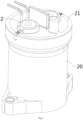
- Figure 1 shows an illustrative perspective view of a contactor according to an exemplary embodiment of the present invention
- Figure 2 shows an axial cross-sectional view of a contactor according to an exemplary embodiment of the present invention
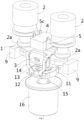
- Figure 3 shows an illustrative perspective view of the static terminal 2, movable terminal assembly, and magnetic blowing magnet 9 of a contactor according to an exemplary embodiment of the present invention
- Figure 4 shows a cross-sectional view of the static terminal 2, movable terminal assembly, and magnetic blowing magnet 9 of a contactor according to an exemplary embodiment of the present invention.
- a contactor in an exemplary embodiment of the present invention, includes: an insulation outer housing 20, a pair of static terminals 2, a movable terminal 1, a first magnetic conductor 3, a static bracket 5, a second magnetic conductor 4, and an elastic member 6.
- the pair of static terminals 2 are arranged in the insulation outer housing 20 and stationary relative to the insulation outer housing 20.
- the movable terminal 1 is arranged in the insulation outer housing 20 and can be moved between a closed position in contact with the static terminal 2 and an opened position separated from the static terminal 2.
- the first magnetic conductor 3 is fixed to the movable terminal 1 to move synchronously with the movable terminal 1.
- the static bracket 5 is arranged in the insulation outer housing 20 and stationary relative to the insulation outer housing 20.
- the second magnetic conductor 4 is movably arranged in the static bracket 5.
- the elastic member 6 is arranged between the static bracket 5 and the second magnetic conductor 4.
- the second magnetic conductor 4 and the static terminal 2 are arranged at the same side of the movable terminal 1, and the second magnetic conductor 4 is floatable supported in the static bracket 5 by the elastic member 6, so that the distance between the first magnetic conductor 3 and the second magnetic conductor 4 is inversely proportional to the current flowing through the movable terminal 1 and the static terminal 2. That is to say, as the current flowing through the movable terminal 1 and the static terminal 2 increases, the distance between the first magnetic conductor 3 and the second magnetic conductor 4 will decrease. When the current flowing through the movable terminal 1 and the static terminal 2 decreases, the distance between the first magnetic conductor 3 and the second magnetic conductor 4 will increase.
- the distance between the first magnetic conductor 3 and the second magnetic conductor 4 is relatively large, resulting in a smaller electromagnetic attraction applied between the movable terminal 1 and the static terminal 2 by the first magnetic conductor 3 and the second magnetic conductor 4, which will not affect the normal connection and disconnection operation of the contactor.
- the distance between the first magnetic conductor 3 and the second magnetic conductor 4 becomes very small, resulting in a very large electromagnetic attraction applied between the movable and static terminals 1 and 2 by the first magnetic conductor 3 and the second magnetic conductor 4, improving the ability of the contactor to withstand the short circuit current.
- the static bracket 5 includes a bottom plate 5b, a side plate 5a and an inner cavity defined by the bottom plate 5b and the side plate 5a.
- the second magnetic conductor 4 is accommodated in the inner cavity of the static bracket 5, and the elastic member 6 is compressed between the second magnetic conductor 4 and the bottom plate 5b of the static bracket 5.
- a guide rib (not shown) extending vertically is formed on one of the side plate 5b of the static bracket 5 and the side face of the second magnetic conductor 4, and a guide groove (not shown) is formed on the other of the side plate 5b of the static bracket 5 and the side face of the second magnetic conductor 4.
- the guide rib is mated with the guide groove to guide the second magnetic conductor 4 to move vertically relative to the static bracket 5.
- the contactor further includes an insulation inner housing 7, which is arranged in the insulation outer housing 20 and has an inner chamber served as an arc extinguishing chamber 7a.
- the static terminal 2 is fixed to the insulation inner housing 7 and extends into the arc extinguishing chamber 7a, and the static bracket 5 is located in the arc extinguishing chamber 7a and is fixed to the insulation inner housing 7.
- the static bracket 5 further includes a connecting part 5c, which is connected to the upper side of the side plate 5a and extends upwards.
- a hole (not shown) is formed on the insulation inner housing 7, and the connecting part 5c is inserted into the hole of the insulation inner housing 7 to fix the static bracket 5 to the insulation inner housing 7.
- a barbed protrusion is formed on the connecting part 5c, and the barbed protrusion on the connecting part 5c is in an interference fit with the hole wall of the hole of the insulation inner housing 7. This can prevent the connection part 5c from being pulled out.
- the elastic member 6 and the second magnetic conductor 4 are located in the arc extinguishing chamber 7a and are detachably assembled together.
- an installation slot is formed on the second magnetic conductor 4, and the elastic member 6 is embedded in the installation slot of the second magnetic conductor 4.
- the contactor further includes a pair of magnetic blowing magnets 9, which are arranged in the arc extinguishing chamber 7a and stationary relative to the static terminal 2.
- the static terminal 2 has a contact end 2a for contact with the movable terminal 1.
- the pair of magnetic blowing magnets 9 are respectively arranged adjacent to the contact ends 2a of the pair of static terminals 2.
- a magnetic field intensity generated by the magnetic blowing magnet 9 itself at the contact end 2a of the static terminal 2 adjacent to the magnetic blowing magnet 9 is higher than a predetermined magnetic field intensity, in order to extinguish an electric arc between the movable terminal 1 and the static terminal 2 through magnetic blowing.
- the direction of the electromagnetic force exerted by the magnetic field generated by the magnetic blowing magnet 9 on the electric arc between the static terminal 2 and the movable terminal 1 is horizontal.
- one magnetic blowing magnets 9 is adjacent to the contact end 2a of one static terminal 2, and the other magnetic blowing magnet 9 is adjacent to the contact end 2a of the other static terminal 2.
- the direction of the electromagnetic force exerted by the magnetic field generated by one magnetic blowing magnet 9 on the electric arc between one static terminal 2 and the movable terminal 1 is the first horizontal direction.
- the direction of the electromagnetic force exerted by the magnetic field generated by the other magnetic blowing magnet 9 on the electric arc between the other static terminal 2 and the movable terminal 1 is the first horizontal direction or a second horizontal direction opposite to the first horizontal direction.
- the contactor also includes an insulation end cap 8.
- the insulation end cap 8 includes a cover plate 8a and a pair of support parts 8b.
- the cover plate 8a is installed onto the bottom opening of the insulation inner housing 7.
- the pair of support parts 8b are connected to the cover plate 8a and located in the arc extinguishing chamber 7a.
- the pair of magnetic blowing magnets 9 are respectively fixed to the pair of support parts 8b of insulation end caps 8.
- a recess is formed on the support part 8b, and the magnetic blowing magnet 9 is embedded in the recess on the support part 8b.
- the contactor further includes an insulation base 11, a support substrate 12, a contact spring 13, and a limit bracket 14.
- the insulation base 11 is located in the arc extinguishing chamber 7a and supported on the cover plate 8a of the insulation end cap 8.
- the support substrate 12 is fixed to the insulation base 11.
- the contact spring 13 is compressed between the second magnetic conductor 4 and the support substrate 12 to provide a contact force between the movable terminal 1 and the static terminal 2.
- the limit bracket 14 is fixed to the support substrate 12 to limit the movement direction and distance of the movable terminal 1 relative to the support substrate 12.
- the contactor further includes a drive shaft 15, and the upper end of the drive shaft 15 extends into the arc extinguishing chamber 7a and is fixed to the insulation base 11.
- the insulation base 11 electrically isolates the drive shaft 15 from the support substrate 12.
- the insulation base 11 is an injection molded part formed on the support substrate 12 and drive shaft 15, so that the insulation base 11, the support substrate 12 and the drive shaft 15 are formed into an integral piece.
- the contactor further comprises a magnetic core 16, which is formed with a central through hole.
- the drive shaft 15 passes through the central through hole of the magnetic core 16 and is connected to the magnetic core 16.
- the contactor further comprises a coil skeleton 17, a coil 18, and a magnetic plate 10.
- the coil skeleton 17 is installed in the insulation outer housing 20.
- the coil 18 is wound around the coil skeleton 17.
- the magnetic plate 10 is supported on the top of the coil skeleton 17.
- the magnetic core 16 is movably arranged in the coil skeleton 17, and the cover plate 8a of the insulation end cap 8 is supported on the top surface of the magnetic plate 10.
- the contactor also includes a return spring (not shown).
- the return spring is compressed between the magnetic core 16 and the magnetic plate 10.
- the drive shaft 15 drives the movable terminal 1 from the closed position to the opened position under the elastic return force of the return spring.
- the contactor further includes a metal inner shell 19, which is arranged in the insulation outer housing 20.
- the insulation inner housing 7, insulation end cap 8, magnetic plate 10, coil skeleton 17, and coil 18 are accommodated in the metal inner shell 19.
- the contactor also includes an insulated top cover 21.
- the insulation top cover 21 is installed on the top opening of the insulation outer housing 20.
- the pair of static terminals 2 extend to the outside of the insulated top cover 21 for electrical connection to connecting terminals (not shown).
- the elastic member 6 can be a spring or an elastic block.
- the elastic element 6 can be a spiral spring or an elastic body made of elastic material.
- a cavity structure can be formed inside the elastic body, for example, to increase the elasticity of the elastic body.
Landscapes
- Physics & Mathematics (AREA)
- Electromagnetism (AREA)
- Arc-Extinguishing Devices That Are Switches (AREA)
- Contacts (AREA)
Applications Claiming Priority (1)
| Application Number | Priority Date | Filing Date | Title |
|---|---|---|---|
| CN202222385971.5U CN218299710U (zh) | 2022-09-08 | 2022-09-08 | 接触器 |
Publications (1)
| Publication Number | Publication Date |
|---|---|
| EP4336532A1 true EP4336532A1 (de) | 2024-03-13 |
Family
ID=84813871
Family Applications (1)
| Application Number | Title | Priority Date | Filing Date |
|---|---|---|---|
| EP23195342.3A Pending EP4336532A1 (de) | 2022-09-08 | 2023-09-05 | Kontaktor |
Country Status (4)
| Country | Link |
|---|---|
| US (1) | US12437947B2 (de) |
| EP (1) | EP4336532A1 (de) |
| JP (1) | JP2024039003A (de) |
| CN (1) | CN218299710U (de) |
Citations (4)
| Publication number | Priority date | Publication date | Assignee | Title |
|---|---|---|---|---|
| DE202018006167U1 (de) * | 2018-05-23 | 2019-05-29 | Ellenberger & Poensgen Gmbh | Trennvorrichtung zur Gleichstromunterbrechung eines Strompfades sowie Schutzschalter |
| CN112582215A (zh) * | 2019-09-27 | 2021-03-30 | 昆山国力源通新能源科技有限公司 | 高压直流继电器的触头结构 |
| WO2021136401A1 (zh) * | 2019-12-31 | 2021-07-08 | 厦门宏发电力电器有限公司 | 一种能够抗短路电流及灭弧的直流继电器 |
| WO2021238388A1 (zh) * | 2020-05-29 | 2021-12-02 | 比亚迪股份有限公司 | 继电器 |
Family Cites Families (3)
| Publication number | Priority date | Publication date | Assignee | Title |
|---|---|---|---|---|
| JP3321963B2 (ja) * | 1994-02-22 | 2002-09-09 | 株式会社デンソー | プランジャ型電磁継電器 |
| JP4321256B2 (ja) * | 2003-12-22 | 2009-08-26 | オムロン株式会社 | 電磁継電器 |
| JP5990028B2 (ja) * | 2012-04-13 | 2016-09-07 | 富士電機機器制御株式会社 | 接点装置及びこれを使用した電磁開閉器 |
-
2022
- 2022-09-08 CN CN202222385971.5U patent/CN218299710U/zh active Active
-
2023
- 2023-09-05 JP JP2023143342A patent/JP2024039003A/ja active Pending
- 2023-09-05 EP EP23195342.3A patent/EP4336532A1/de active Pending
- 2023-09-07 US US18/462,821 patent/US12437947B2/en active Active
Patent Citations (4)
| Publication number | Priority date | Publication date | Assignee | Title |
|---|---|---|---|---|
| DE202018006167U1 (de) * | 2018-05-23 | 2019-05-29 | Ellenberger & Poensgen Gmbh | Trennvorrichtung zur Gleichstromunterbrechung eines Strompfades sowie Schutzschalter |
| CN112582215A (zh) * | 2019-09-27 | 2021-03-30 | 昆山国力源通新能源科技有限公司 | 高压直流继电器的触头结构 |
| WO2021136401A1 (zh) * | 2019-12-31 | 2021-07-08 | 厦门宏发电力电器有限公司 | 一种能够抗短路电流及灭弧的直流继电器 |
| WO2021238388A1 (zh) * | 2020-05-29 | 2021-12-02 | 比亚迪股份有限公司 | 继电器 |
Also Published As
| Publication number | Publication date |
|---|---|
| CN218299710U (zh) | 2023-01-13 |
| US20240087826A1 (en) | 2024-03-14 |
| US12437947B2 (en) | 2025-10-07 |
| JP2024039003A (ja) | 2024-03-21 |
Similar Documents
| Publication | Publication Date | Title |
|---|---|---|
| EP4141903B1 (de) | Relais | |
| EP4604157A1 (de) | Relais | |
| CN212161708U (zh) | 触头装置及电磁开关 | |
| US4766273A (en) | High current double-break electrical contactor | |
| CN212136360U (zh) | 400a一组常闭新型直流接触器 | |
| CN113745060A (zh) | 一种基于绝缘和灭弧的新能源高压直流继电器 | |
| EP4336532A1 (de) | Kontaktor | |
| KR102839999B1 (ko) | 초소형 접점간 고내압 긴수명의 힌지형 릴레이 | |
| CN108400061B (zh) | 高压直流通断器 | |
| US12080496B2 (en) | Contactor with integrated drive shaft and yoke | |
| CN109920704B (zh) | 抗洛仑兹力继电器 | |
| CN220341134U (zh) | 一种继电器接触单元和继电器 | |
| US12198881B2 (en) | Contact apparatus and electromagnetic switch | |
| US20260051447A1 (en) | Contactor | |
| CN217822596U (zh) | 一种能快速灭弧的磁保持继电器 | |
| CN120221335A (zh) | 继电器 | |
| CN119446853A (zh) | 一种继电器触点组件和继电器 | |
| CN219998120U (zh) | 接触器 | |
| CN117936326A (zh) | 一种继电器 | |
| EP4718489A1 (de) | Bewegliche kontaktanordnung eines schützes und schütz | |
| US20260112560A1 (en) | Direct current relay with auxiliary contact | |
| CN218385044U (zh) | 一种继电器 | |
| CN217822460U (zh) | 一种高效灭弧磁保持继电器 | |
| CN219842931U (zh) | 增加爬电距离的继电器 | |
| CN219163272U (zh) | 一种用于监测继电器触点状态的辅助触点结构 |
Legal Events
| Date | Code | Title | Description |
|---|---|---|---|
| PUAI | Public reference made under article 153(3) epc to a published international application that has entered the european phase |
Free format text: ORIGINAL CODE: 0009012 |
|
| STAA | Information on the status of an ep patent application or granted ep patent |
Free format text: STATUS: THE APPLICATION HAS BEEN PUBLISHED |
|
| AK | Designated contracting states |
Kind code of ref document: A1 Designated state(s): AL AT BE BG CH CY CZ DE DK EE ES FI FR GB GR HR HU IE IS IT LI LT LU LV MC ME MK MT NL NO PL PT RO RS SE SI SK SM TR |
|
| STAA | Information on the status of an ep patent application or granted ep patent |
Free format text: STATUS: REQUEST FOR EXAMINATION WAS MADE |
|
| 17P | Request for examination filed |
Effective date: 20240910 |
|
| RBV | Designated contracting states (corrected) |
Designated state(s): AL AT BE BG CH CY CZ DE DK EE ES FI FR GB GR HR HU IE IS IT LI LT LU LV MC ME MK MT NL NO PL PT RO RS SE SI SK SM TR |
|
| STAA | Information on the status of an ep patent application or granted ep patent |
Free format text: STATUS: EXAMINATION IS IN PROGRESS |
|
| 17Q | First examination report despatched |
Effective date: 20251119 |