EP4336137A1 - Scale thickness measuring method - Google Patents
Scale thickness measuring method Download PDFInfo
- Publication number
- EP4336137A1 EP4336137A1 EP22866994.1A EP22866994A EP4336137A1 EP 4336137 A1 EP4336137 A1 EP 4336137A1 EP 22866994 A EP22866994 A EP 22866994A EP 4336137 A1 EP4336137 A1 EP 4336137A1
- Authority
- EP
- European Patent Office
- Prior art keywords
- scale
- eddy
- heat transfer
- transfer pipe
- measuring method
- Prior art date
- Legal status (The legal status is an assumption and is not a legal conclusion. Google has not performed a legal analysis and makes no representation as to the accuracy of the status listed.)
- Pending
Links
- 238000000034 method Methods 0.000 title claims abstract description 44
- 239000000523 sample Substances 0.000 claims abstract description 46
- 238000012546 transfer Methods 0.000 claims abstract description 39
- 238000001514 detection method Methods 0.000 claims abstract description 38
- 230000005284 excitation Effects 0.000 claims abstract description 28
- 230000002093 peripheral effect Effects 0.000 claims abstract description 13
- 238000011088 calibration curve Methods 0.000 claims abstract description 9
- 238000010586 diagram Methods 0.000 description 5
- 230000000712 assembly Effects 0.000 description 3
- 238000000429 assembly Methods 0.000 description 3
- 238000005452 bending Methods 0.000 description 3
- 230000000694 effects Effects 0.000 description 3
- 238000005259 measurement Methods 0.000 description 3
- 238000012360 testing method Methods 0.000 description 3
- 238000010248 power generation Methods 0.000 description 2
- 238000013461 design Methods 0.000 description 1
- 239000000463 material Substances 0.000 description 1
Images

Classifications
-
- G—PHYSICS
- G01—MEASURING; TESTING
- G01B—MEASURING LENGTH, THICKNESS OR SIMILAR LINEAR DIMENSIONS; MEASURING ANGLES; MEASURING AREAS; MEASURING IRREGULARITIES OF SURFACES OR CONTOURS
- G01B7/00—Measuring arrangements characterised by the use of electric or magnetic techniques
- G01B7/02—Measuring arrangements characterised by the use of electric or magnetic techniques for measuring length, width or thickness
- G01B7/06—Measuring arrangements characterised by the use of electric or magnetic techniques for measuring length, width or thickness for measuring thickness
- G01B7/10—Measuring arrangements characterised by the use of electric or magnetic techniques for measuring length, width or thickness for measuring thickness using magnetic means, e.g. by measuring change of reluctance
- G01B7/105—Measuring arrangements characterised by the use of electric or magnetic techniques for measuring length, width or thickness for measuring thickness using magnetic means, e.g. by measuring change of reluctance for measuring thickness of coating
-
- G—PHYSICS
- G01—MEASURING; TESTING
- G01N—INVESTIGATING OR ANALYSING MATERIALS BY DETERMINING THEIR CHEMICAL OR PHYSICAL PROPERTIES
- G01N27/00—Investigating or analysing materials by the use of electric, electrochemical, or magnetic means
- G01N27/72—Investigating or analysing materials by the use of electric, electrochemical, or magnetic means by investigating magnetic variables
- G01N27/82—Investigating or analysing materials by the use of electric, electrochemical, or magnetic means by investigating magnetic variables for investigating the presence of flaws
- G01N27/90—Investigating or analysing materials by the use of electric, electrochemical, or magnetic means by investigating magnetic variables for investigating the presence of flaws using eddy currents
- G01N27/9013—Arrangements for scanning
- G01N27/902—Arrangements for scanning by moving the sensors
-
- G—PHYSICS
- G01—MEASURING; TESTING
- G01N—INVESTIGATING OR ANALYSING MATERIALS BY DETERMINING THEIR CHEMICAL OR PHYSICAL PROPERTIES
- G01N27/00—Investigating or analysing materials by the use of electric, electrochemical, or magnetic means
- G01N27/72—Investigating or analysing materials by the use of electric, electrochemical, or magnetic means by investigating magnetic variables
- G01N27/82—Investigating or analysing materials by the use of electric, electrochemical, or magnetic means by investigating magnetic variables for investigating the presence of flaws
- G01N27/90—Investigating or analysing materials by the use of electric, electrochemical, or magnetic means by investigating magnetic variables for investigating the presence of flaws using eddy currents
- G01N27/904—Investigating or analysing materials by the use of electric, electrochemical, or magnetic means by investigating magnetic variables for investigating the presence of flaws using eddy currents with two or more sensors
-
- Y—GENERAL TAGGING OF NEW TECHNOLOGICAL DEVELOPMENTS; GENERAL TAGGING OF CROSS-SECTIONAL TECHNOLOGIES SPANNING OVER SEVERAL SECTIONS OF THE IPC; TECHNICAL SUBJECTS COVERED BY FORMER USPC CROSS-REFERENCE ART COLLECTIONS [XRACs] AND DIGESTS
- Y02—TECHNOLOGIES OR APPLICATIONS FOR MITIGATION OR ADAPTATION AGAINST CLIMATE CHANGE
- Y02E—REDUCTION OF GREENHOUSE GAS [GHG] EMISSIONS, RELATED TO ENERGY GENERATION, TRANSMISSION OR DISTRIBUTION
- Y02E30/00—Energy generation of nuclear origin
- Y02E30/30—Nuclear fission reactors
Definitions
- the present disclosure relates to a scale thickness measuring method.
- Priority is claimed on Japanese Patent Application No. 2021-146218, filed September 8, 2021 , the content of which is incorporated herein by reference.
- a steam generator in a nuclear power generation facility accommodates a plurality of heat transfer pipes. It is known that attachments called scale are generated on the outer peripheral surface of the heat transfer pipe as time goes by. If the thickness of such scale becomes too large, the heat transfer performance of the heat transfer pipe may be affected. Therefore, there has been an increasing demand for a technique that can remotely measure and evaluate the thickness of the scale.
- Patent Document 1 discloses a technique for measuring a thickness of scale using a probe that generates an eddy current.
- a coil is excited while inserting and moving the probe into the heat transfer pipe. Then, a magnetic field is generated in the scale and this magnetic field in turn generates an induced voltage in a sensor coil. Since the impedance of the coil at this time is a function of the thickness of the scale, it is said that the thickness of the scale can be determined by measuring the impedance. That is, this technique uses a self-guided standard comparison method.
- Patent Document 1 Japanese Unexamined Patent Application, First Publication No. H5-87510
- the present disclosure has been made to solve the above-described problems and an object thereof is to provide a scale thickness measuring method capable of performing more accurate measurement.
- a scale thickness measuring method is a scale thickness measuring method of measuring a thickness of scale attached to an outer peripheral surface of a heat transfer pipe extending in a direction of an axis and having a cylindrical shape centered on the axis by using an eddy-current probe, which is provided with an excitation coil generating an eddy current, and a pair of detection coils which are provided integrally with the excitation coil and detecting axial and circumferential components of a magnetic field formed by the eddy current, the scale thickness measuring method including: obtaining a reference point in a region of the heat transfer pipe to which the scale is not attached by calculating a difference between the axial and circumferential components of the magnetic field detected by the pair of detection coils; moving the eddy-current probe inside the heat transfer pipe in the direction of the axis while inserting the eddy-current probe into the heat transfer pipe; calculating the difference between the axial and circumferential components of the magnetic field detected by the pair of
- an eddy-current probe 1 according to an embodiment of the present disclosure and a scale thickness measuring method using the eddy-current probe will be described with reference to FIGS. 1 to 5 .
- FIG. 1 A configuration of the eddy-current probe 1 will be described with reference to FIGS. 1 to 3 .
- the eddy-current probe 1 is used while being inserted into a heat transfer pipe 90.
- a plurality of the heat transfer pipes 90 are provided inside, for example, a steam generator.
- the heat transfer pipe 90 extends along an axis O and has a cylindrical shape centered on the axis O. Attachments called scale are generated on the outer peripheral surface of the heat transfer pipe 90 as time goes by.
- the eddy-current probe 1 is used to measure the thickness of the scale.
- the eddy-current probe 1 includes a probe body 10 and a plurality of coil assemblies 11. Various wirings are accommodated inside the probe body 10.
- the probe body 10 is formed in a columnar shape extending along the axis O.
- the plurality of coil assemblies 11 are provided at the tip of the probe body 10 at intervals in the circumferential direction of the axis O.
- the coil assembly 11 includes one excitation coil 11a and a pair of detection coils 11b.
- the excitation coil 11a has a ring shape.
- the excitation coil 11a is disposed inside the probe body 10 so that the diameter direction is orthogonal to the inner peripheral surface of the heat transfer pipe 90. Further, the excitation coil 11a is disposed in a posture inclined at an angle of about 45° with respect to the axis O.
- the excitation coil 11a generates an eddy current in the vicinity of the inner peripheral surface of the heat transfer pipe 90 by being excited by a voltage supplied from the outside.
- the detection coil 11b is integrally provided on the outer peripheral side (that is, the side of the heat transfer pipe 90) in relation to the excitation coil 11a.
- Each detection coil 11b has, for example, a rectangular ring shape and extends along the inner peripheral surface of the heat transfer pipe 90.
- the detection coil 11b is disposed in a posture inclined at an angle of about 45° with respect to the axis O and a pair of the detection coils are provided at intervals in the inclined direction.
- Each detection coil 11b is used to capture a change in magnetic field caused by the eddy current generated by the excitation coil 11a. For example, changes in the circumferential magnetic field and the axial magnetic field are detected by a detection voltage difference between the detection coil 11b on one side and the detection coil 11b on the other side.
- this measuring method includes a reference point determination step S1, a probe movement step S2, a difference calculation step S3, a drift amount calculation step S4, and a scale thickness calculation step S5.
- the magnetic field detected by the pair of detection coils 11b is measured in a region in which no scale is attached in the heat transfer pipe 90 or on a sample (calibration test piece) having the same material and dimensions as the heat transfer pipe 90. Specifically, a difference between the component in the direction of the axis O and the component in the circumferential direction of the magnetic field is calculated and a point in which the difference becomes zero is set as a reference point. That is, the reference point determination step S 1 is performed to correct the detection result of the eddy-current probe 1 in a state in which there is no scale.
- the probe movement step S2 is performed.
- the eddy-current probe 1 is inserted into the heat transfer pipe 90 and is moved in the direction of the axis O. At this time, an eddy current is generated near the inner peripheral surface of the heat transfer pipe 90 by the excitation coil 11a.
- the scale attached to the outer peripheral surface of the heat transfer pipe 90 changes the magnetic field detected by the detection coil 11b.
- the difference between the component in the direction of the axis O and the component in the circumferential direction of the magnetic field generated by the pair of detection coils 11b is calculated.
- this difference value shifts (drifts) from the reference point.
- drift amount calculation step S4 a change amount (drift amount) from the reference point is calculated.
- the scale thickness calculation step S5 is performed.
- the scale thickness is calculated by comparing the drift amount with the calibration curve obtained in advance. As indicated by an example of FIG. 5 , the drift amount and the scale thickness are in a proportional relationship. That is, when the drift amount increases, the scale thickness also tends to increase.
- the scale thickness is obtained on the basis of the calibration curve. With the above steps, all steps of the scale thickness measuring method are completed.
- the eddy-current probe 1 and the scale thickness measuring method according to this embodiment have the above-described configuration.
- a difference between the component in the direction of the axis O and the component in the circumferential direction of the magnetic field detected by the pair of detection coils 11b is calculated and this difference is compared with the reference point to obtain the drift amount.
- the thickness of the scale is calculated from the calibration curve obtained in advance on the basis of the drift amount. In this way, since a so-called differential method is used, it is possible to accurately measure the scale thickness while being robust against external disturbances such as bending and stretching of the probe. As a result, it is possible to more precisely and accurately evaluate the scale thickness.
- the excitation coil 11a and the pair of detection coils 11b are arranged in a direction inclined with respect to the axis O, it is possible to generate an eddy current in a wider range of the direction of the axis O and the circumferential direction and to stably detect a change in magnetic field caused by the eddy current in a wider range.
- the plurality of coil assemblies 11 are arranged at intervals in the circumferential direction. Accordingly, it is possible to stably and accurately measure the scale thickness over the entire region of the heat transfer pipe 90 in the circumferential direction.
- the embodiment of the present disclosure has been described above with reference to the drawings, the detailed configuration is not limited to this embodiment and design changes and the like may be made without departing from the gist of the present disclosure.
- a configuration has been described in which the coil assembly 11 is inclined by 45° with respect to the axis O.
- the posture of the coil assembly 11 is not limited thereto and the inclined angle may be smaller than 45° if the coil assembly is slightly inclined with respect to the axis O.
- the detection coil 11b is provided on the outer peripheral side of the excitation coil 11a.
- the detection coil 11b is disposed to surround the excitation coil 11a.
- a pair of excitation and detection coils are provided and each is disposed along the direction of the axis O and the circumferential direction. In any method, the same operation and effect as those of the above-described embodiment can be obtained.
- the present disclosure relates to a method of measuring a thickness of scale attached inside a heat transfer pipe included in a steam generator of a nuclear power generation facility. According to the method of the present disclosure, it is possible to accurately measure the thickness of the scale.
Landscapes
- Chemical & Material Sciences (AREA)
- General Physics & Mathematics (AREA)
- Physics & Mathematics (AREA)
- Electrochemistry (AREA)
- Health & Medical Sciences (AREA)
- Life Sciences & Earth Sciences (AREA)
- Analytical Chemistry (AREA)
- Biochemistry (AREA)
- General Health & Medical Sciences (AREA)
- Chemical Kinetics & Catalysis (AREA)
- Immunology (AREA)
- Pathology (AREA)
- Measurement Of Length, Angles, Or The Like Using Electric Or Magnetic Means (AREA)
- Investigating Or Analyzing Materials By The Use Of Magnetic Means (AREA)
Abstract
Description
- The present disclosure relates to a scale thickness measuring method. Priority is claimed on
Japanese Patent Application No. 2021-146218, filed September 8, 2021 - A steam generator in a nuclear power generation facility accommodates a plurality of heat transfer pipes. It is known that attachments called scale are generated on the outer peripheral surface of the heat transfer pipe as time goes by. If the thickness of such scale becomes too large, the heat transfer performance of the heat transfer pipe may be affected. Therefore, there has been an increasing demand for a technique that can remotely measure and evaluate the thickness of the scale.
- For example,
Patent Document 1 below discloses a technique for measuring a thickness of scale using a probe that generates an eddy current. In this technique, a coil is excited while inserting and moving the probe into the heat transfer pipe. Then, a magnetic field is generated in the scale and this magnetic field in turn generates an induced voltage in a sensor coil. Since the impedance of the coil at this time is a function of the thickness of the scale, it is said that the thickness of the scale can be determined by measuring the impedance. That is, this technique uses a self-guided standard comparison method. - Patent Document 1:
Japanese Unexamined Patent Application, First Publication No. H5-87510 - However, since the above self-guided standard comparison type probe was vulnerable to bending or stretching, rattling, and temperature changes, there was a problem that the thickness of the scale was not accurately measured.
- The present disclosure has been made to solve the above-described problems and an object thereof is to provide a scale thickness measuring method capable of performing more accurate measurement.
- In order to solve the above-described problems, a scale thickness measuring method according to the present disclosure is a scale thickness measuring method of measuring a thickness of scale attached to an outer peripheral surface of a heat transfer pipe extending in a direction of an axis and having a cylindrical shape centered on the axis by using an eddy-current probe, which is provided with an excitation coil generating an eddy current, and a pair of detection coils which are provided integrally with the excitation coil and detecting axial and circumferential components of a magnetic field formed by the eddy current, the scale thickness measuring method including: obtaining a reference point in a region of the heat transfer pipe to which the scale is not attached by calculating a difference between the axial and circumferential components of the magnetic field detected by the pair of detection coils; moving the eddy-current probe inside the heat transfer pipe in the direction of the axis while inserting the eddy-current probe into the heat transfer pipe; calculating the difference between the axial and circumferential components of the magnetic field detected by the pair of detection coils; obtaining a drift amount by comparing the difference with the reference point; and calculating the thickness of the scale from a calibration curve obtained in advance on the basis of the drift amount.
- According to the present disclosure, it is possible to provide a scale thickness measuring method capable of performing more accurate measurement.
-
-
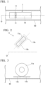
FIG. 1 is a schematic view showing a configuration of an eddy-current probe according to an embodiment of the present disclosure. -
FIG. 2 is a diagram showing a configuration of a detection coil and an excitation coil included in the eddy-current probe according to the embodiment of the present disclosure and is a diagram as viewed from the inside in the radial direction of a heat transfer pipe. -
FIG. 3 is a diagram showing a configuration of the detection coil and the excitation coil included in the eddy-current probe according to the embodiment of the present disclosure and is a diagram as viewed from the direction of the axis of the heat transfer pipe. -
FIG. 4 is a process diagram showing a scale thickness measuring method according to the embodiment of the present disclosure. -
FIG. 5 is an example of a calibration curve showing a relationship between the thickness of the scale and the drift amount of the magnetic field due to the scale. - Hereinafter, an eddy-
current probe 1 according to an embodiment of the present disclosure and a scale thickness measuring method using the eddy-current probe will be described with reference toFIGS. 1 to 5 . - A configuration of the eddy-
current probe 1 will be described with reference toFIGS. 1 to 3 . As shown inFIG. 1 , the eddy-current probe 1 is used while being inserted into aheat transfer pipe 90. A plurality of theheat transfer pipes 90 are provided inside, for example, a steam generator. Theheat transfer pipe 90 extends along an axis O and has a cylindrical shape centered on the axis O. Attachments called scale are generated on the outer peripheral surface of theheat transfer pipe 90 as time goes by. The eddy-current probe 1 is used to measure the thickness of the scale. - The eddy-
current probe 1 includes aprobe body 10 and a plurality ofcoil assemblies 11. Various wirings are accommodated inside theprobe body 10. Theprobe body 10 is formed in a columnar shape extending along the axis O. The plurality ofcoil assemblies 11 are provided at the tip of theprobe body 10 at intervals in the circumferential direction of the axis O. - As shown in
FIGS. 2 and 3 , thecoil assembly 11 includes oneexcitation coil 11a and a pair ofdetection coils 11b. Theexcitation coil 11a has a ring shape. Theexcitation coil 11a is disposed inside theprobe body 10 so that the diameter direction is orthogonal to the inner peripheral surface of theheat transfer pipe 90. Further, theexcitation coil 11a is disposed in a posture inclined at an angle of about 45° with respect to the axis O. Theexcitation coil 11a generates an eddy current in the vicinity of the inner peripheral surface of theheat transfer pipe 90 by being excited by a voltage supplied from the outside. - The
detection coil 11b is integrally provided on the outer peripheral side (that is, the side of the heat transfer pipe 90) in relation to theexcitation coil 11a. Eachdetection coil 11b has, for example, a rectangular ring shape and extends along the inner peripheral surface of theheat transfer pipe 90. Like theexcitation coil 11a, thedetection coil 11b is disposed in a posture inclined at an angle of about 45° with respect to the axis O and a pair of the detection coils are provided at intervals in the inclined direction. - Each
detection coil 11b is used to capture a change in magnetic field caused by the eddy current generated by theexcitation coil 11a. For example, changes in the circumferential magnetic field and the axial magnetic field are detected by a detection voltage difference between thedetection coil 11b on one side and thedetection coil 11b on the other side. - Next, a scale thickness measuring method using the eddy-
current probe 1 will be described. As shown inFIG. 4 , this measuring method includes a reference point determination step S1, a probe movement step S2, a difference calculation step S3, a drift amount calculation step S4, and a scale thickness calculation step S5. - In the reference point determination step S1, the magnetic field detected by the pair of
detection coils 11b is measured in a region in which no scale is attached in theheat transfer pipe 90 or on a sample (calibration test piece) having the same material and dimensions as theheat transfer pipe 90. Specifically, a difference between the component in the direction of the axis O and the component in the circumferential direction of the magnetic field is calculated and a point in which the difference becomes zero is set as a reference point. That is, the reference pointdetermination step S 1 is performed to correct the detection result of the eddy-current probe 1 in a state in which there is no scale. - Next, the probe movement step S2 is performed. In the probe movement step S2, the eddy-
current probe 1 is inserted into theheat transfer pipe 90 and is moved in the direction of the axis O. At this time, an eddy current is generated near the inner peripheral surface of theheat transfer pipe 90 by theexcitation coil 11a. - While the eddy-
current probe 1 is moved, the scale attached to the outer peripheral surface of theheat transfer pipe 90 changes the magnetic field detected by thedetection coil 11b. In the subsequent difference calculation step S3, the difference between the component in the direction of the axis O and the component in the circumferential direction of the magnetic field generated by the pair ofdetection coils 11b is calculated. In a state in which the scale is attached, this difference value shifts (drifts) from the reference point. In the drift amount calculation step S4, a change amount (drift amount) from the reference point is calculated. - Next, the scale thickness calculation step S5 is performed. In this step S5, the scale thickness is calculated by comparing the drift amount with the calibration curve obtained in advance. As indicated by an example of
FIG. 5 , the drift amount and the scale thickness are in a proportional relationship. That is, when the drift amount increases, the scale thickness also tends to increase. In step S5, the scale thickness is obtained on the basis of the calibration curve. With the above steps, all steps of the scale thickness measuring method are completed. - Conventionally, it was common to use a probe using a method called a self-guided standard comparison method when measuring the scale thickness. In this method, one coil acts on a test object and the other coil acts on a reference object to detect differences. This method is used when it is necessary to detect an absolute amount such as a thinning amount in the test object. However, there was a problem in that accurate measurement was not easily performed due to the large influence of lift-off noise.
- Therefore, the eddy-
current probe 1 and the scale thickness measuring method according to this embodiment have the above-described configuration. According to the configuration and method, a difference between the component in the direction of the axis O and the component in the circumferential direction of the magnetic field detected by the pair ofdetection coils 11b is calculated and this difference is compared with the reference point to obtain the drift amount. Further, the thickness of the scale is calculated from the calibration curve obtained in advance on the basis of the drift amount. In this way, since a so-called differential method is used, it is possible to accurately measure the scale thickness while being robust against external disturbances such as bending and stretching of the probe. As a result, it is possible to more precisely and accurately evaluate the scale thickness. - Further, according to the above-described configuration, since the
excitation coil 11a and the pair ofdetection coils 11b are arranged in a direction inclined with respect to the axis O, it is possible to generate an eddy current in a wider range of the direction of the axis O and the circumferential direction and to stably detect a change in magnetic field caused by the eddy current in a wider range. - Further, according to the above-described configuration, the plurality of
coil assemblies 11 are arranged at intervals in the circumferential direction. Accordingly, it is possible to stably and accurately measure the scale thickness over the entire region of theheat transfer pipe 90 in the circumferential direction. - Although the embodiment of the present disclosure has been described above with reference to the drawings, the detailed configuration is not limited to this embodiment and design changes and the like may be made without departing from the gist of the present disclosure. For example, in the above-described embodiment, a configuration has been described in which the
coil assembly 11 is inclined by 45° with respect to the axis O. However, the posture of thecoil assembly 11 is not limited thereto and the inclined angle may be smaller than 45° if the coil assembly is slightly inclined with respect to the axis O. - Further, in the above-described embodiment, an example has been described in which the
detection coil 11b is provided on the outer peripheral side of theexcitation coil 11a. However, it is also possible to adopt a configuration in which thedetection coil 11b is disposed to surround theexcitation coil 11a. Further, it is also possible to adopt a configuration in which a pair of excitation and detection coils are provided and each is disposed along the direction of the axis O and the circumferential direction. In any method, the same operation and effect as those of the above-described embodiment can be obtained. - The scale thickness measuring method described in each embodiment is understood, for example, as below.
- (1) A scale thickness measuring method according to a first aspect is a scale thickness measuring method of measuring a thickness of scale attached to the outer peripheral surface of the heat transfer pipe 90 extending in the direction of the axis O and having a cylindrical shape centered on the axis O by using the eddy-current probe 1, which is provided with the excitation coil 11a generating an eddy current, and the pair of detection coils 11b which are provided integrally with the excitation coil 11a and detecting axial and circumferential components of a magnetic field formed by the eddy current, the scale thickness measuring method includes: step S1 of obtaining a reference point in a region of the heat transfer pipe 90 to which the scale is not attached by calculating a difference between the axial and circumferential components of the magnetic field detected by the pair of detection coils 11b; step S2 of moving the eddy-current probe 1 inside the heat transfer pipe 90 in the direction of the axis O while inserting the eddy-current probe into the heat transfer pipe 90; step S3 of calculating the difference between the axial and circumferential components of the magnetic field detected by the pair of detection coils 11b; step S4 of obtaining a drift amount by comparing the difference with the reference point; and step S5 of calculating the thickness of the scale from a calibration curve obtained in advance on the basis of the drift amount.
According to the above-described configuration, a difference between the component in the direction of the axis O and the component in the circumferential direction of the magnetic field detected by the pair ofdetection coils 11b is calculated and this difference is compared with the reference point to obtain the drift amount. Further, the thickness of the scale is calculated from the calibration curve obtained in advance on the basis of the drift amount. In this way, since a so-called differential method is used, it is possible to accurately measure the scale thickness while being robust against external disturbances such as bending and stretching of the probe. - (2) According to the scale thickness measuring method of a second aspect, in the scale thickness measuring method according to the first aspect, the
excitation coil 11a and the pair ofdetection coils 11b may be arranged in a direction inclined with respect to the axis O.
According to the above-described configuration, since theexcitation coil 11a and the pair ofdetection coils 11b are arranged in a direction inclined with respect to the axis O, it is possible to generate an eddy current in a wider range in the direction of the axis O and the circumferential direction and to stably detect a change in magnetic field caused by this eddy current in a wider range. - (3) According to the scale thickness measuring method of a third aspect, in the scale thickness measuring method according to the first or second aspect, a plurality of the excitation coils 11a and the pair of
detection coils 11b may be arranged at intervals in the circumferential direction of the eddy-current probe 1. - According to the above-described configuration, it is possible to stably and accurately measure the scale thickness over the entire region of the
heat transfer pipe 90 in the circumferential direction. - The present disclosure relates to a method of measuring a thickness of scale attached inside a heat transfer pipe included in a steam generator of a nuclear power generation facility. According to the method of the present disclosure, it is possible to accurately measure the thickness of the scale.
-
- 90 Heat transfer pipe
- 1 Eddy-current probe
- 10 Probe body
- 11 Coil assembly
- 11a Excitation coil
- 11b Detection coil
- O Axis
Claims (3)
- A scale thickness measuring method of measuring a thickness of scale attached to an outer peripheral surface of a heat transfer pipe extending in a direction of an axis and having a cylindrical shape centered on the axis by using an eddy-current probe, which is provided with an excitation coil generating an eddy current, and a pair of detection coils which are provided integrally with the excitation coil and detecting axial and circumferential components of a magnetic field formed by the eddy current, the scale thickness measuring method comprising:obtaining a reference point in a region of the heat transfer pipe to which the scale is not attached by calculating a difference between the axial and circumferential components of the magnetic field detected by the pair of detection coils;moving the eddy-current probe inside the heat transfer pipe in the direction of the axis while inserting the eddy-current probe into the heat transfer pipe;calculating the difference between the axial and circumferential components of the magnetic field detected by the pair of detection coils;obtaining a drift amount by comparing the difference with the reference point; andcalculating the thickness of the scale from a calibration curve obtained in advance on the basis of the drift amount.
- The scale thickness measuring method according to claim 1,
wherein the excitation coil and the pair of detection coils are arranged in a direction inclined with respect to the axis. - The scale thickness measuring method according to claim 1 or 2,
wherein a plurality of the excitation coils and the pair of detection coils are arranged at intervals in the circumferential direction of the eddy-current probe.
Applications Claiming Priority (2)
| Application Number | Priority Date | Filing Date | Title |
|---|---|---|---|
| JP2021146218A JP7702839B2 (en) | 2021-09-08 | 2021-09-08 | How to measure scale thickness |
| PCT/JP2022/020802 WO2023037664A1 (en) | 2021-09-08 | 2022-05-19 | Scale thickness measuring method |
Publications (2)
| Publication Number | Publication Date |
|---|---|
| EP4336137A1 true EP4336137A1 (en) | 2024-03-13 |
| EP4336137A4 EP4336137A4 (en) | 2024-09-18 |
Family
ID=85506319
Family Applications (1)
| Application Number | Title | Priority Date | Filing Date |
|---|---|---|---|
| EP22866994.1A Pending EP4336137A4 (en) | 2021-09-08 | 2022-05-19 | METHOD FOR MEASURING SCALE THICKNESS |
Country Status (4)
| Country | Link |
|---|---|
| US (1) | US12510347B2 (en) |
| EP (1) | EP4336137A4 (en) |
| JP (1) | JP7702839B2 (en) |
| WO (1) | WO2023037664A1 (en) |
Families Citing this family (2)
| Publication number | Priority date | Publication date | Assignee | Title |
|---|---|---|---|---|
| JP2025011847A (en) * | 2023-07-12 | 2025-01-24 | 株式会社Ihi検査計測 | Eddy current inspection device and eddy current inspection method |
| CN119470617B (en) * | 2024-11-11 | 2025-05-27 | 江苏省特种设备安全监督检验研究院 | Multi-frequency array vortex detection equipment and method thereof |
Family Cites Families (16)
| Publication number | Priority date | Publication date | Assignee | Title |
|---|---|---|---|---|
| US4808927A (en) * | 1987-02-19 | 1989-02-28 | Atomic Energy Of Canada Limited | Circumferentially compensating eddy current probe with alternately polarized receiver coil |
| JPH0587510A (en) * | 1991-09-26 | 1993-04-06 | Mitsubishi Heavy Ind Ltd | Method for measuring scale thickness |
| JP3343860B2 (en) * | 1998-08-06 | 2002-11-11 | 三菱重工業株式会社 | Eddy current testing probe |
| US6549006B2 (en) * | 2000-04-07 | 2003-04-15 | Cuong Duy Le | Eddy current measurements of thin-film metal coatings using a selectable calibration standard |
| JP4232937B2 (en) | 2000-12-19 | 2009-03-04 | 株式会社原子力エンジニアリング | Processing method of eddy current flaw detection signal |
| US7705589B2 (en) | 2008-02-19 | 2010-04-27 | Korea Research Institute Of Standards And Science | Sensor for detecting surface defects of metal tube using eddy current method |
| JP5159436B2 (en) | 2008-05-29 | 2013-03-06 | 東北電力株式会社 | Method and apparatus for detecting scale adhesion |
| JP5404369B2 (en) * | 2009-12-18 | 2014-01-29 | 三菱重工業株式会社 | Inspection device |
| JP5383597B2 (en) | 2010-06-16 | 2014-01-08 | 株式会社日立製作所 | Eddy current inspection apparatus and inspection method |
| JP5791279B2 (en) * | 2011-01-06 | 2015-10-07 | 三菱重工業株式会社 | Deposit measuring apparatus, deposit measuring method, and deposit measuring program |
| JP5968658B2 (en) | 2012-03-23 | 2016-08-10 | 住友精密工業株式会社 | Film thickness measuring method and film thickness measuring apparatus |
| JP6288640B2 (en) * | 2014-02-28 | 2018-03-07 | 三菱日立パワーシステムズ株式会社 | Eddy current flaw detection probe, eddy current flaw detection apparatus, and eddy current flaw detection method |
| JP6452880B1 (en) | 2018-06-13 | 2019-01-16 | 東亜非破壊検査株式会社 | Method and apparatus for inspecting flaws or defects in tubular body |
| JP7245673B2 (en) | 2019-03-05 | 2023-03-24 | 株式会社テイエルブイ | Probes and thickness gauges |
| EP3881791A1 (en) | 2020-03-18 | 2021-09-22 | Globus Medical, Inc. | System for neuronavigation registration and robotic trajectory guidance, and related methods and devices |
| JP7374032B2 (en) | 2020-03-24 | 2023-11-06 | 一般財団法人発電設備技術検査協会 | How to create a master curve for thickness measurement using electromagnetic measurements and how to use it |
-
2021
- 2021-09-08 JP JP2021146218A patent/JP7702839B2/en active Active
-
2022
- 2022-05-19 EP EP22866994.1A patent/EP4336137A4/en active Pending
- 2022-05-19 US US18/566,327 patent/US12510347B2/en active Active
- 2022-05-19 WO PCT/JP2022/020802 patent/WO2023037664A1/en not_active Ceased
Also Published As
| Publication number | Publication date |
|---|---|
| WO2023037664A1 (en) | 2023-03-16 |
| EP4336137A4 (en) | 2024-09-18 |
| US12510347B2 (en) | 2025-12-30 |
| JP7702839B2 (en) | 2025-07-04 |
| US20240255268A1 (en) | 2024-08-01 |
| JP2023039183A (en) | 2023-03-20 |
Similar Documents
| Publication | Publication Date | Title |
|---|---|---|
| US8610426B2 (en) | Carburization sensing method | |
| US12510347B2 (en) | Scale thickness measuring method | |
| JP2010164306A (en) | Method and device for hardened depth | |
| US20080246468A1 (en) | Method and algorithms for inspection of longitudinal defects in an eddy current inspection system | |
| EP3324180B1 (en) | Defect measurement method and testing probe | |
| US11428590B2 (en) | Method for estimating a bearing load using strain parameters to account for contact angle variation | |
| CN112666395A (en) | Non-contact metal material conductivity measurement method and system | |
| US11519796B2 (en) | Stress-induced magnetic field signal acquisition method and stress measurement method based thereon | |
| RU2696909C1 (en) | Method and device for hot measurement, during rolling, size of metal profiles | |
| US9304110B2 (en) | Carburization sensing method | |
| JP6740077B2 (en) | CALIBRATION DEVICE FOR NON-DESTRUCTIVE INSPECTION MEASUREMENT SYSTEM AND NON-DESTRUCTIVE INSPECTION MEASUREMENT METHOD | |
| Procházka et al. | Non-contact systems for monitoring blade vibrations of steam turbines | |
| JP6378554B2 (en) | Nondestructive inspection apparatus and nondestructive inspection method | |
| JP5372866B2 (en) | Eddy current flaw detection method and eddy current flaw detection system | |
| JP6081107B2 (en) | Gap measuring device, method and program | |
| JPS62235505A (en) | Measurement of thickness of lined pipe | |
| KR20150047272A (en) | Apparatus and method for defect detection | |
| CN108267502A (en) | The eddy detection system and detection method of case depth | |
| CN107702733A (en) | Induction position detector | |
| JP5145073B2 (en) | Eddy current flaw detection method and eddy current flaw detection apparatus | |
| US9804286B2 (en) | Method of optimising the output of a sensor for indicating the relative location of a mettalic object | |
| JP2024017286A (en) | Turbine blade inspection method | |
| JP6688687B2 (en) | Nondestructive inspection device and nondestructive inspection method | |
| JP2016153753A (en) | Pipe flaw detector and pipe flaw detection method | |
| JPH11211407A (en) | Position detection method for moving device in pipe |
Legal Events
| Date | Code | Title | Description |
|---|---|---|---|
| STAA | Information on the status of an ep patent application or granted ep patent |
Free format text: STATUS: THE INTERNATIONAL PUBLICATION HAS BEEN MADE |
|
| PUAI | Public reference made under article 153(3) epc to a published international application that has entered the european phase |
Free format text: ORIGINAL CODE: 0009012 |
|
| STAA | Information on the status of an ep patent application or granted ep patent |
Free format text: STATUS: REQUEST FOR EXAMINATION WAS MADE |
|
| 17P | Request for examination filed |
Effective date: 20231205 |
|
| AK | Designated contracting states |
Kind code of ref document: A1 Designated state(s): AL AT BE BG CH CY CZ DE DK EE ES FI FR GB GR HR HU IE IS IT LI LT LU LV MC MK MT NL NO PL PT RO RS SE SI SK SM TR |
|
| A4 | Supplementary search report drawn up and despatched |
Effective date: 20240819 |
|
| RIC1 | Information provided on ipc code assigned before grant |
Ipc: G01N 27/904 20210101ALI20240812BHEP Ipc: G01B 7/06 20060101AFI20240812BHEP |
|
| DAV | Request for validation of the european patent (deleted) | ||
| DAX | Request for extension of the european patent (deleted) |