EP4335993A1 - Reinigungsgerät für schwimmbecken - Google Patents
Reinigungsgerät für schwimmbecken Download PDFInfo
- Publication number
- EP4335993A1 EP4335993A1 EP23169896.0A EP23169896A EP4335993A1 EP 4335993 A1 EP4335993 A1 EP 4335993A1 EP 23169896 A EP23169896 A EP 23169896A EP 4335993 A1 EP4335993 A1 EP 4335993A1
- Authority
- EP
- European Patent Office
- Prior art keywords
- gear
- transmission gear
- main body
- driving wheel
- swimming pool
- Prior art date
- Legal status (The legal status is an assumption and is not a legal conclusion. Google has not performed a legal analysis and makes no representation as to the accuracy of the status listed.)
- Granted
Links
Images

Classifications
-
- E—FIXED CONSTRUCTIONS
- E04—BUILDING
- E04H—BUILDINGS OR LIKE STRUCTURES FOR PARTICULAR PURPOSES; SWIMMING OR SPLASH BATHS OR POOLS; MASTS; FENCING; TENTS OR CANOPIES, IN GENERAL
- E04H4/00—Swimming or splash baths or pools
- E04H4/14—Parts, details or accessories not otherwise provided for
- E04H4/16—Parts, details or accessories not otherwise provided for specially adapted for cleaning
- E04H4/1654—Self-propelled cleaners
-
- A—HUMAN NECESSITIES
- A47—FURNITURE; DOMESTIC ARTICLES OR APPLIANCES; COFFEE MILLS; SPICE MILLS; SUCTION CLEANERS IN GENERAL
- A47L—DOMESTIC WASHING OR CLEANING; SUCTION CLEANERS IN GENERAL
- A47L11/00—Machines for cleaning floors, carpets, furniture, walls, or wall coverings
- A47L11/40—Parts or details of machines not provided for in groups A47L11/02 - A47L11/38, or not restricted to one of these groups, e.g. handles, arrangements of switches, skirts, buffers, levers
- A47L11/4063—Driving means; Transmission means therefor
-
- A—HUMAN NECESSITIES
- A47—FURNITURE; DOMESTIC ARTICLES OR APPLIANCES; COFFEE MILLS; SPICE MILLS; SUCTION CLEANERS IN GENERAL
- A47L—DOMESTIC WASHING OR CLEANING; SUCTION CLEANERS IN GENERAL
- A47L2201/00—Robotic cleaning machines, i.e. with automatic control of the travelling movement or the cleaning operation
Definitions
- the application relates to the technical field of swimming pool cleaning, and in particular to a robot swimming pool cleaner.
- a robot swimming pool cleaner is a robot cleaner invented for cleaning the swimming pool.
- the swimming pool always has garbage, such as dust, human body exfoliative objects, tree leaves, insect corpse, etc.
- the robot swimming pool cleaner may collect the garbage so as to clean the swimming pool, however, the robot swimming pool cleaner is limited in size and influenced by a layout of different parts; an engine compartment and a battery compartment may occupy most of the space, resulting in insufficient garbage loading capacity, frequent cleaning of the garbage bin, inconvenience for use and poor user experience.
- a technical problem to be solved by the present application is to provide a robot swimming pool cleaner with a higher space utilization rate.
- the robot swimming pool cleaner includes a main body and a first driving wheel rotatably disposed on the main body, the main body is therein provided with a sealed compartment and a garbage bin, the sealed compartment is therein provided with a motor, an output shaft of the motor is provided with a first output gear, the first output gear is located out of the sealed compartment, and an inner side of the first driving wheel is provided with a first inner gear in meshed connection with the first output gear.
- the robot swimming pool cleaner further includes a second driving wheel rotatably disposed on the main body, the first driving wheel is disposed close to a front end of the main body, and the second driving wheel is disposed close to a rear end of the main body.
- the first driving wheel is further provided with a first outer gear
- a side wall of the main body is further provided with a gear component
- the first outer gear is in meshed connection with the gear component.
- the robot swimming pool cleaner further includes a rolling brush connected with the gear component.
- a wheel hub of the first inner gear, the first outer gear and the first driving wheel are integrally formed by injection molding.
- the gear component includes a first transmission gear and a second transmission gear which are in meshed connection, the first outer gear is meshed with the first transmission gear, and the rolling brush is connected to the second transmission gear.
- first outer gear, the first transmission gear and the second transmission gear are distributed triangularly, and connecting lines for central rotating axes of the first outer gear, the first transmission gear and the second transmission gear on the same plane form a triangle.
- the side wall of the main body is provided with a third transmission gear, a fourth transmission gear and a fifth transmission gear;
- the output shaft of the motor is further provided with a second output gear;
- an inner side of the second driving wheel is provided with a second inner gear;
- the second output gear is in meshed connection with the third transmission gear;
- the third transmission gear is in meshed connection with the fourth transmission gear;
- the fourth transmission gear and the fifth transmission gear are connected to an identical rotating shaft; and the fifth transmission gear is in meshed connection with the second inner gear.
- first output gear and the fifth transmission gear are symmetrically disposed relative to a vertical plane where a central axis of the third transmission gear is located.
- the second output gear and the fourth transmission gear are symmetrically disposed relative to the vertical plane where the central axis of the third transmission gear is located.
- a side surface of the main body is provided with a protection plate, the protection plate and the main body are connected to form an enclosed space, and the second output gear, the third transmission gear and the fourth transmission gear are disposed in the enclosed space.
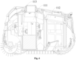
- the present application has the following beneficial effects: the main body is therein provided with the sealed compartment and the garbage bin, the sealed compartment is therein provided with the motor, the output shaft of the motor is provided with the first output gear; the first inner gear is provided on the inner side of the first driving wheel, thus the whole sealed compartment provided with the motor may be close to one end of the main body, and a larger space is reserved on the other side of the main body for the garbage bin, thereby improving the loading capacity of the garbage bin.
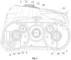
- a robot swimming pool cleaner includes a main body 1 and a first driving wheel 2 rotatably disposed on the main body 1, the main body 1 is therein provided with a sealed compartment 111 and a garbage bin, the sealed compartment 111 is therein provided with a motor 113, an output shaft of the motor 113 is provided with a first output gear 12, the first output gear 12 is located out of the sealed compartment 111, and an inner side of the first driving wheel 2 is provided with a first inner gear 21 in meshed connection with the first output gear 12.
- the present application has the following beneficial effects: the first inner gear 21 is provided on the inner side of the first driving wheel 2, the first output gear 12 is provided on the output shaft of the motor 113, the whole sealed compartment 111 provided with the motor 113 may be disposed close to one end of the main body, and a larger space is reserved on the other side of the main body 1 for the garbage bin, thereby improving the loading capacity of the garbage bin.
- the robot swimming pool cleaner further includes a second driving wheel 3 rotatably disposed on the main body, the first driving wheel 2 and the second driving wheel 3 are respectively disposed close to two ends of the main body 1.
- the motor 113 is meshed with the first inner gear 21 through the first output gear 12 to drive the first driving wheel 2 to rotate.
- first driving wheel 2 is further provided with a first outer gear 22
- a side wall of the main body 1 is further provided with a gear component
- the first outer gear 22 is meshed with the gear component.
- the robot swimming pool cleaner further includes a rolling brush 4 connected to the gear component.
- the first driving wheel 2 drives the rolling brush 4 to rotate, thereby beneficially simplifying a structure of the robot swimming pool cleaner.
- a wheel hub of the first inner gear 21, the first outer gear 22 and the first driving wheel 2 are integrally formed by injection molding.
- the wheel hub of the first inner gear 21, the first outer gear 22 and the first driving wheel 2 are integrally formed by injection molding, thereby shortening the installation time, improving the production efficiency and beneficially enhancing the overall stability of the wheel.
- the gear component includes a first transmission gear 14 and a second transmission gear 15 which are meshed with each other, the first outer gear 22 is meshed with the first transmission gear 14, and the rolling brush 4 is connected to the second transmission gear 15.
- a position for installation of the rolling brush 4 on the robot swimming pool cleaner may be adjusted, such that the position for installation of the rolling brush 4 is more flexible.
- first outer gear 22, the first transmission gear 14 and the second transmission gear 15 are distributed triangularly, and connecting lines for central rotating axes of the first outer gear, the first transmission gear and the second transmission gear on the same plane form a triangle.
- first outer gear 22, the first transmission gear 14 and the second transmission gear 15 are distributed triangularly, thereby saving a space, such that the first transmission gear 14 and the second transmission gear 15 may be contained inside the first driving wheel 2 to achieve a protection effect on the first transmission gear 14 and the second transmission gear 15.
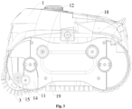
- the side wall of the main body 1 is provided with a third transmission gear 16, a fourth transmission gear 17 and a fifth transmission gear 18;
- the output shaft of the motor 113 is further provided with a second output gear 13;
- the inner side of the second driving wheel 3 is provided with a second inner gear 31;
- the second output gear 13 is meshed with the third transmission gear 16;
- the third transmission gear 16 is meshed with the fourth transmission gear 17;
- the fourth transmission gear 17 and the fifth transmission gear 18 are connected to an identical rotating shaft; and the fifth transmission gear 18 is meshed with the second inner gear 31.
- the motor 113 simultaneously drives the first driving wheel 2 and the second driving wheel 3 to realize four-wheel drive, thereby improving the obstacle crossing capability of the robot swimming pool cleaner.
- first output gear 12 and the fifth transmission gear 18 are symmetrically disposed relative to a vertical plane where a central axis of the third transmission gear 16 is located.
- first output gear 12 and the fifth transmission gear 18 are symmetrically disposed, thereby decreasing the number of molds and reducing the cost.
- the second output gear 13 and the fourth transmission gear 17 are symmetrically disposed relative to the vertical plane where the central axis of the third transmission gear 16 is located.
- first output gear 13 and the fourth transmission gear 17 are symmetrically disposed, thereby decreasing the number of molds and reducing the cost.
- a side surface of the main body 1 is provided with a protection plate 19, the protection plate 19 and the main body 1 are connected to form an enclosed space, and the second output gear 13, the third transmission gear 16 and the fourth transmission gear 17 are disposed in the enclosed space.
- the enclosed space may protect the gears and prevent particles such as sand and the like, from entering the gears, thereby avoiding gear sticking.
- embodiment I of the present application provides a robot swimming pool cleaner, including a main body 1 and a first driving wheel 2 rotatably disposed on the main body 1; the main body 1 is therein provided with a sealed compartment 111 and a garbage bin; the sealed compartment 111 is therein provided with a motor 113; an output shaft of the motor 113 is provided with a first output gear 12; the first output gear 12 is located out of the sealed compartment 111; and inner sides of the first driving wheel 2 are provided with a first inner gear 21 meshed with the first output gear 12.
- the robot swimming pool cleaner further includes a second driving wheel 3 rotatably disposed on the main body 1, the first driving wheel 2 and the second driving wheel 3 are respectively disposed close to two ends of the main body 1.
- the motor 113 are connected to the first output gear 12; the first output gear 12 are disposed in blank spaces above a left side in the first output gear 12, thus, useless spaces in the first driving wheel 2 are fully utilized; there are two motors 113; the output shafts of the two motors 113 are respectively connected to the first driving wheel 2 on two sides of the robot swimming pool cleaner, the first driving wheel 2 is a rear wheel, and the second driving wheel 3 is a front wheel, or the first driving wheel 2 is the front wheel, and the second driving wheel 3 is the rear wheel; the first driving wheel 2 and the second driving wheel 3 are the same in structure, the first inner gear 21 and second inner gear 31 are the same in structure, and first outer gear 22 and a second outer wheel 32 are the same in structure so as to improve the universality of the wheels, such that the wheels are convenient
- the first driving wheel 2 is further provided with the first outer gear 22
- a side wall of the main body 1 is further provided with a gear component
- the first outer gear 22 is meshed with the gear component.
- the robot swimming pool cleaner further includes a rolling brush 4 connected to the gear component.
- the gear component includes a first transmission gear 14 and a second transmission gear 15 which are meshed with each other, the first transmission gear 14 is meshed with the second transmission gear 15, and the rolling brush 4 is connected to the second transmission gear 15.
- the gear component is located in the first driving wheel 2, the rolling brush 4 is located at the bottom of a rear end of the main body 1, and the rolling brush 4 is driven by the first driving wheel 2.
- the gear component may be located in the second driving wheel 3, the gear component is meshed with the second outer gear 32, the rolling brush 4 is located at the bottom of a front end of the main body 1, the rolling brush 4 is driven by the second driving wheel 3; the gear component may include one or three transmission gears in an equal quantity, and a rotation speed of the rolling brush 4 may be changed by providing a plurality of transmission gears.
- wheel hubs of the first inner gear 21, the first outer gear 22 and the first driving wheel 2 are integrally formed by injection molding; the first outer gear 22, the first transmission gear 14 and the second transmission gear 15 are distributed triangularly; and connecting lines for central rotating axes of the first outer gear 22, the first transmission gear 14 and the second transmission gear 15 on the same plane form a triangle.
- an outer side of the main body 1 is provided with a bottom shell 11; the first transmission gear 14 and the second transmission gear 15 are disposed on the bottom shell 11; and the first transmission gear 14 and the second transmission gear 15 are located in spaces below a right side in the first driving wheel 2.
- the outer side of the main body 1 may be not provided with the bottom shell 11; the first transmission gear 14 and the second transmission gear 15 may be located outside the first driving wheel 2; or part regions of the first transmission gear 14 and the second transmission gear 15 are located inside the first driving wheel 2, and part regions of the first transmission gear 14 and the second transmission gear 15 are located outside the first driving wheel 2.
- the side wall of the main body 1 is provided with a third transmission gear 16, a fourth transmission gear 17 and a fifth transmission gear 18;
- the output shaft of the motor 113 is further provided with a second output gear 13;
- the inner sides of the second driving wheel 3 is provided with a second inner gear 31;
- the second output gear 13 is meshed with the third transmission gear 16;
- the third transmission gear 16 is meshed with the fourth transmission gear 17;
- the fourth transmission gear 17 and the fifth transmission gear 18 are connected to an identical rotating shaft; and the fifth transmission gear 18 is meshed with the second inner gear 31.
- the third transmission gear 16, the fourth transmission gear 17 and the fifth transmission gear 18 are disposed on the bottom shell 11; while driving the first driving wheel 2 through the third transmission gear 16, the fourth transmission gear 17 and the fifth transmission gear 18, the motor 113 may drive the second driving wheel 3, the fifth transmission gear 18 is located in the space above the right side in the second driving wheel 3.
- the first output gear 12 and the fifth transmission gear 18 are symmetrically disposed relative to a vertical plane where the central axis of the third transmission gear 16 is located; the second output gear 13 and the fourth transmission gear 17 are symmetrically disposed relative to the vertical plane where the central axis of the third transmission gear 16 is located.
- the first output gear 12 and the fifth transmission gear 18 are the same in structure and size
- the second output gear 13 and the fourth transmission gear 17 are the same in structure and size
- the third transmission gear 16 is located in a central region between the first driving wheel 2 and the second driving wheel 3.
- a side surface of the main body 1 is provided with a protection plate 19, the protection plate 19 and the main body 1 are connected to form an enclosed space, and the second output gear 13, the third transmission gear 16 and the fourth transmission gear 17 are disposed in the enclosed space.
- two sides of the main body 1 are provided with the protection plate 19, and the protection plate 19 and the bottom shell 11 disposed on the main body 1 are matched to form the enclosed space configured to protect the gears exposed to the outside.
- the first inner gear is provided on the inner side of the first driving wheel
- the first output gear is provided on the output shaft of the motor
- the whole sealed compartment provided with the motor may be close to one end of the main body, and a larger space is reserved on the other side of the main body for the garbage bin, thereby improving the loading capacity of the garbage bin
- the first outer gear and the gear component which is connected to the rolling brush are provided in the first driving wheel, such that, while driving the first driving wheel, the motor may drive the rolling brush to rotate
- the output shaft of the motor is provided with the second output gear
- the side wall of the main body is provided with the transmission gear meshed with the second inner gear disposed on the inner side of the second driving wheel, such that the motor may simultaneously drive the first driving wheel and the second driving wheel of the robot swimming pool cleaner to realize four-wheel drive, thereby improving the obstacle crossing capability of the robot swimming pool cleaner.
Landscapes
- Engineering & Computer Science (AREA)
- Architecture (AREA)
- Civil Engineering (AREA)
- Structural Engineering (AREA)
- Toys (AREA)
- Electric Suction Cleaners (AREA)
- Manipulator (AREA)
- Electric Vacuum Cleaner (AREA)
Applications Claiming Priority (1)
| Application Number | Priority Date | Filing Date | Title |
|---|---|---|---|
| CN202222465553.7U CN218815528U (zh) | 2022-09-06 | 2022-09-06 | 泳池清洁机器人 |
Publications (2)
| Publication Number | Publication Date |
|---|---|
| EP4335993A1 true EP4335993A1 (de) | 2024-03-13 |
| EP4335993B1 EP4335993B1 (de) | 2025-06-11 |
Family
ID=85859678
Family Applications (1)
| Application Number | Title | Priority Date | Filing Date |
|---|---|---|---|
| EP23169896.0A Active EP4335993B1 (de) | 2022-09-06 | 2023-04-25 | Reinigungsroboter für schwimmbecken |
Country Status (6)
| Country | Link |
|---|---|
| US (1) | US20240076890A1 (de) |
| EP (1) | EP4335993B1 (de) |
| CN (1) | CN218815528U (de) |
| AU (1) | AU2023202604B2 (de) |
| CA (1) | CA3197967A1 (de) |
| MX (1) | MX2023007722A (de) |
Cited By (1)
| Publication number | Priority date | Publication date | Assignee | Title |
|---|---|---|---|---|
| CN120244246A (zh) * | 2025-06-04 | 2025-07-04 | 烟台龙港泵业股份有限公司 | 一种离心泵叶轮生产用自动焊接装置 |
Families Citing this family (4)
| Publication number | Priority date | Publication date | Assignee | Title |
|---|---|---|---|---|
| USD1049524S1 (en) * | 2022-08-12 | 2024-10-29 | Shenzhen Aiper Intelligent Co., Ltd. | Swimming pool cleaner |
| CN117019638B (zh) * | 2023-05-25 | 2026-02-13 | 河南黎明重工科技股份有限公司 | 一种闭路开路互补式循环风力筛分工艺制砂楼 |
| CN223075242U (zh) * | 2024-08-07 | 2025-07-08 | 深圳市元鼎智能创新有限公司 | 一种水下清洁器 |
| CN120270106B (zh) * | 2025-06-05 | 2025-09-19 | 潍柴动力股份有限公司 | 整车电池系统的控制方法、装置、介质和系统 |
Citations (3)
| Publication number | Priority date | Publication date | Assignee | Title |
|---|---|---|---|---|
| US20180066443A1 (en) * | 2016-09-02 | 2018-03-08 | Aqua Products, Inc. | Modular swimming pool cleaner |
| WO2019214391A1 (zh) * | 2018-05-11 | 2019-11-14 | 宁波普乐菲智能科技有限公司 | 水下清洁机器人轮驱传动结构 |
| CN110670918B (zh) * | 2019-09-24 | 2021-08-24 | 浙江斯普泳池有限公司 | 一种泳池清理设备 |
-
2022
- 2022-09-06 CN CN202222465553.7U patent/CN218815528U/zh active Active
-
2023
- 2023-04-25 EP EP23169896.0A patent/EP4335993B1/de active Active
- 2023-04-26 CA CA3197967A patent/CA3197967A1/en active Pending
- 2023-04-27 US US18/308,136 patent/US20240076890A1/en active Pending
- 2023-04-28 AU AU2023202604A patent/AU2023202604B2/en active Active
- 2023-06-26 MX MX2023007722A patent/MX2023007722A/es unknown
Patent Citations (3)
| Publication number | Priority date | Publication date | Assignee | Title |
|---|---|---|---|---|
| US20180066443A1 (en) * | 2016-09-02 | 2018-03-08 | Aqua Products, Inc. | Modular swimming pool cleaner |
| WO2019214391A1 (zh) * | 2018-05-11 | 2019-11-14 | 宁波普乐菲智能科技有限公司 | 水下清洁机器人轮驱传动结构 |
| CN110670918B (zh) * | 2019-09-24 | 2021-08-24 | 浙江斯普泳池有限公司 | 一种泳池清理设备 |
Cited By (1)
| Publication number | Priority date | Publication date | Assignee | Title |
|---|---|---|---|---|
| CN120244246A (zh) * | 2025-06-04 | 2025-07-04 | 烟台龙港泵业股份有限公司 | 一种离心泵叶轮生产用自动焊接装置 |
Also Published As
| Publication number | Publication date |
|---|---|
| AU2023202604B2 (en) | 2024-09-19 |
| CA3197967A1 (en) | 2024-03-06 |
| MX2023007722A (es) | 2024-03-07 |
| AU2023202604A1 (en) | 2024-03-21 |
| CN218815528U (zh) | 2023-04-07 |
| US20240076890A1 (en) | 2024-03-07 |
| EP4335993B1 (de) | 2025-06-11 |
Similar Documents
| Publication | Publication Date | Title |
|---|---|---|
| EP4335993A1 (de) | Reinigungsgerät für schwimmbecken | |
| EP4667682A1 (de) | Getriebevorrichtung und schwimmbeckenreinigungsroboter | |
| CN209668691U (zh) | 一种旋转顶升机构及包含该旋转顶升机构的潜伏式agv | |
| CN215016892U (zh) | 一种扫地机器人边轮 | |
| CN213064501U (zh) | 一种用于电动拖把的齿轮驱动结构 | |
| CN212277683U (zh) | 一种电力防尘用电力柜 | |
| CN219988971U (zh) | 一种多轮组差速驱动器 | |
| CN205315618U (zh) | 一种带动辊子组转动的割台专用齿轮箱 | |
| CN221829517U (zh) | 一种收割机底盘行走逆转箱 | |
| JP3134258U (ja) | 自動掃除機の障害物超越装置 | |
| CN221669682U (zh) | 一种自驱式轮毂 | |
| CN201470105U (zh) | 玩具四驱车的底盘 | |
| TWM321280U (en) | Barrier-crossing device of robot vacuum cleaner | |
| CN223031244U (zh) | 水面清洁机器人 | |
| CN213695990U (zh) | 一种自动驱动行走的行李箱 | |
| CN222495967U (zh) | 一种新型防水防尘脚轮 | |
| CN2065050U (zh) | 无需电源的吸尘刷 | |
| CN211659264U (zh) | 一种新型玩具四驱装置 | |
| CN218792060U (zh) | 电机总成一体式双刷清洁设备 | |
| CN223231592U (zh) | 一种玉米种植用施肥装置 | |
| CN224138853U (zh) | 一种塔式直流减速电机 | |
| CN110585741A (zh) | 三轮特技遥控车 | |
| CN112400482B (zh) | 驱动结构及具有该驱动结构的自动行走设备 | |
| CN209534738U (zh) | 一种四驱车 | |
| CN221912034U (zh) | 一种关节组件及机器人 |
Legal Events
| Date | Code | Title | Description |
|---|---|---|---|
| PUAI | Public reference made under article 153(3) epc to a published international application that has entered the european phase |
Free format text: ORIGINAL CODE: 0009012 |
|
| STAA | Information on the status of an ep patent application or granted ep patent |
Free format text: STATUS: EXAMINATION IS IN PROGRESS |
|
| 17P | Request for examination filed |
Effective date: 20230425 |
|
| AK | Designated contracting states |
Kind code of ref document: A1 Designated state(s): AL AT BE BG CH CY CZ DE DK EE ES FI FR GB GR HR HU IE IS IT LI LT LU LV MC ME MK MT NL NO PL PT RO RS SE SI SK SM TR |
|
| GRAP | Despatch of communication of intention to grant a patent |
Free format text: ORIGINAL CODE: EPIDOSNIGR1 |
|
| STAA | Information on the status of an ep patent application or granted ep patent |
Free format text: STATUS: GRANT OF PATENT IS INTENDED |
|
| RIC1 | Information provided on ipc code assigned before grant |
Ipc: E04H 4/16 20060101AFI20250227BHEP |
|
| INTG | Intention to grant announced |
Effective date: 20250313 |
|
| GRAS | Grant fee paid |
Free format text: ORIGINAL CODE: EPIDOSNIGR3 |
|
| GRAA | (expected) grant |
Free format text: ORIGINAL CODE: 0009210 |
|
| STAA | Information on the status of an ep patent application or granted ep patent |
Free format text: STATUS: THE PATENT HAS BEEN GRANTED |
|
| AK | Designated contracting states |
Kind code of ref document: B1 Designated state(s): AL AT BE BG CH CY CZ DE DK EE ES FI FR GB GR HR HU IE IS IT LI LT LU LV MC ME MK MT NL NO PL PT RO RS SE SI SK SM TR |
|
| REG | Reference to a national code |
Ref country code: GB Ref legal event code: FG4D |
|
| REG | Reference to a national code |
Ref country code: CH Ref legal event code: EP |
|
| REG | Reference to a national code |
Ref country code: IE Ref legal event code: FG4D |
|
| REG | Reference to a national code |
Ref country code: DE Ref legal event code: R096 Ref document number: 602023003905 Country of ref document: DE |
|
| P01 | Opt-out of the competence of the unified patent court (upc) registered |
Free format text: CASE NUMBER: APP_28352/2025 Effective date: 20250613 |
|
| PG25 | Lapsed in a contracting state [announced via postgrant information from national office to epo] |
Ref country code: FI Free format text: LAPSE BECAUSE OF FAILURE TO SUBMIT A TRANSLATION OF THE DESCRIPTION OR TO PAY THE FEE WITHIN THE PRESCRIBED TIME-LIMIT Effective date: 20250611 Ref country code: ES Free format text: LAPSE BECAUSE OF FAILURE TO SUBMIT A TRANSLATION OF THE DESCRIPTION OR TO PAY THE FEE WITHIN THE PRESCRIBED TIME-LIMIT Effective date: 20250611 |
|
| REG | Reference to a national code |
Ref country code: LT Ref legal event code: MG9D |
|
| PG25 | Lapsed in a contracting state [announced via postgrant information from national office to epo] |
Ref country code: GR Free format text: LAPSE BECAUSE OF FAILURE TO SUBMIT A TRANSLATION OF THE DESCRIPTION OR TO PAY THE FEE WITHIN THE PRESCRIBED TIME-LIMIT Effective date: 20250912 Ref country code: NO Free format text: LAPSE BECAUSE OF FAILURE TO SUBMIT A TRANSLATION OF THE DESCRIPTION OR TO PAY THE FEE WITHIN THE PRESCRIBED TIME-LIMIT Effective date: 20250911 |
|
| REG | Reference to a national code |
Ref country code: NL Ref legal event code: MP Effective date: 20250611 |
|
| PG25 | Lapsed in a contracting state [announced via postgrant information from national office to epo] |
Ref country code: BG Free format text: LAPSE BECAUSE OF FAILURE TO SUBMIT A TRANSLATION OF THE DESCRIPTION OR TO PAY THE FEE WITHIN THE PRESCRIBED TIME-LIMIT Effective date: 20250611 |
|
| PG25 | Lapsed in a contracting state [announced via postgrant information from national office to epo] |
Ref country code: HR Free format text: LAPSE BECAUSE OF FAILURE TO SUBMIT A TRANSLATION OF THE DESCRIPTION OR TO PAY THE FEE WITHIN THE PRESCRIBED TIME-LIMIT Effective date: 20250611 |
|
| PG25 | Lapsed in a contracting state [announced via postgrant information from national office to epo] |
Ref country code: RS Free format text: LAPSE BECAUSE OF FAILURE TO SUBMIT A TRANSLATION OF THE DESCRIPTION OR TO PAY THE FEE WITHIN THE PRESCRIBED TIME-LIMIT Effective date: 20250911 |
|
| PG25 | Lapsed in a contracting state [announced via postgrant information from national office to epo] |
Ref country code: LV Free format text: LAPSE BECAUSE OF FAILURE TO SUBMIT A TRANSLATION OF THE DESCRIPTION OR TO PAY THE FEE WITHIN THE PRESCRIBED TIME-LIMIT Effective date: 20250611 |
|
| PG25 | Lapsed in a contracting state [announced via postgrant information from national office to epo] |
Ref country code: NL Free format text: LAPSE BECAUSE OF FAILURE TO SUBMIT A TRANSLATION OF THE DESCRIPTION OR TO PAY THE FEE WITHIN THE PRESCRIBED TIME-LIMIT Effective date: 20250611 |
|
| PG25 | Lapsed in a contracting state [announced via postgrant information from national office to epo] |
Ref country code: PT Free format text: LAPSE BECAUSE OF FAILURE TO SUBMIT A TRANSLATION OF THE DESCRIPTION OR TO PAY THE FEE WITHIN THE PRESCRIBED TIME-LIMIT Effective date: 20251013 |
|
| REG | Reference to a national code |
Ref country code: AT Ref legal event code: MK05 Ref document number: 1802395 Country of ref document: AT Kind code of ref document: T Effective date: 20250611 |
|
| PG25 | Lapsed in a contracting state [announced via postgrant information from national office to epo] |
Ref country code: IS Free format text: LAPSE BECAUSE OF FAILURE TO SUBMIT A TRANSLATION OF THE DESCRIPTION OR TO PAY THE FEE WITHIN THE PRESCRIBED TIME-LIMIT Effective date: 20251011 |
|
| PG25 | Lapsed in a contracting state [announced via postgrant information from national office to epo] |
Ref country code: SM Free format text: LAPSE BECAUSE OF FAILURE TO SUBMIT A TRANSLATION OF THE DESCRIPTION OR TO PAY THE FEE WITHIN THE PRESCRIBED TIME-LIMIT Effective date: 20250611 Ref country code: AT Free format text: LAPSE BECAUSE OF FAILURE TO SUBMIT A TRANSLATION OF THE DESCRIPTION OR TO PAY THE FEE WITHIN THE PRESCRIBED TIME-LIMIT Effective date: 20250611 |
|
| PG25 | Lapsed in a contracting state [announced via postgrant information from national office to epo] |
Ref country code: CZ Free format text: LAPSE BECAUSE OF FAILURE TO SUBMIT A TRANSLATION OF THE DESCRIPTION OR TO PAY THE FEE WITHIN THE PRESCRIBED TIME-LIMIT Effective date: 20250611 |
|
| PG25 | Lapsed in a contracting state [announced via postgrant information from national office to epo] |
Ref country code: PL Free format text: LAPSE BECAUSE OF FAILURE TO SUBMIT A TRANSLATION OF THE DESCRIPTION OR TO PAY THE FEE WITHIN THE PRESCRIBED TIME-LIMIT Effective date: 20250611 |
|
| PG25 | Lapsed in a contracting state [announced via postgrant information from national office to epo] |
Ref country code: EE Free format text: LAPSE BECAUSE OF FAILURE TO SUBMIT A TRANSLATION OF THE DESCRIPTION OR TO PAY THE FEE WITHIN THE PRESCRIBED TIME-LIMIT Effective date: 20250611 |
|
| PG25 | Lapsed in a contracting state [announced via postgrant information from national office to epo] |
Ref country code: SK Free format text: LAPSE BECAUSE OF FAILURE TO SUBMIT A TRANSLATION OF THE DESCRIPTION OR TO PAY THE FEE WITHIN THE PRESCRIBED TIME-LIMIT Effective date: 20250611 |
|
| REG | Reference to a national code |
Ref country code: DE Ref legal event code: R097 Ref document number: 602023003905 Country of ref document: DE |
|
| PG25 | Lapsed in a contracting state [announced via postgrant information from national office to epo] |
Ref country code: DK Free format text: LAPSE BECAUSE OF FAILURE TO SUBMIT A TRANSLATION OF THE DESCRIPTION OR TO PAY THE FEE WITHIN THE PRESCRIBED TIME-LIMIT Effective date: 20250611 |
|
| PLBE | No opposition filed within time limit |
Free format text: ORIGINAL CODE: 0009261 |
|
| STAA | Information on the status of an ep patent application or granted ep patent |
Free format text: STATUS: NO OPPOSITION FILED WITHIN TIME LIMIT |
|
| PGFP | Annual fee paid to national office [announced via postgrant information from national office to epo] |
Ref country code: FR Payment date: 20260317 Year of fee payment: 4 |
|
| REG | Reference to a national code |
Ref country code: CH Ref legal event code: L10 Free format text: ST27 STATUS EVENT CODE: U-0-0-L10-L00 (AS PROVIDED BY THE NATIONAL OFFICE) Effective date: 20260423 |