EP4334928B1 - Regalbildgebungsvorrichtung für eine regalstütze und regalsystem mit der regalbildgebungsvorrichtung - Google Patents
Regalbildgebungsvorrichtung für eine regalstütze und regalsystem mit der regalbildgebungsvorrichtung Download PDFInfo
- Publication number
- EP4334928B1 EP4334928B1 EP22727900.7A EP22727900A EP4334928B1 EP 4334928 B1 EP4334928 B1 EP 4334928B1 EP 22727900 A EP22727900 A EP 22727900A EP 4334928 B1 EP4334928 B1 EP 4334928B1
- Authority
- EP
- European Patent Office
- Prior art keywords
- shelf
- imaging device
- engaging member
- actuator
- receiving section
- Prior art date
- Legal status (The legal status is an assumption and is not a legal conclusion. Google has not performed a legal analysis and makes no representation as to the accuracy of the status listed.)
- Active
Links
Images


Classifications
-
- G—PHYSICS
- G09—EDUCATION; CRYPTOGRAPHY; DISPLAY; ADVERTISING; SEALS
- G09F—DISPLAYING; ADVERTISING; SIGNS; LABELS OR NAME-PLATES; SEALS
- G09F3/00—Labels, tag tickets, or similar identification or indication means; Seals; Postage or like stamps
- G09F3/08—Fastening or securing by means not forming part of the material of the label itself
- G09F3/18—Casings, frames or enclosures for labels
- G09F3/20—Casings, frames or enclosures for labels for adjustable, removable, or interchangeable labels
- G09F3/208—Electronic labels, Labels integrating electronic displays
-
- G—PHYSICS
- G09—EDUCATION; CRYPTOGRAPHY; DISPLAY; ADVERTISING; SEALS
- G09F—DISPLAYING; ADVERTISING; SIGNS; LABELS OR NAME-PLATES; SEALS
- G09F3/00—Labels, tag tickets, or similar identification or indication means; Seals; Postage or like stamps
- G09F3/08—Fastening or securing by means not forming part of the material of the label itself
- G09F3/18—Casings, frames or enclosures for labels
- G09F3/20—Casings, frames or enclosures for labels for adjustable, removable, or interchangeable labels
- G09F3/202—Casings, frames or enclosures for labels for adjustable, removable, or interchangeable labels for labels being formed by a combination of interchangeable elements, e.g. price labels
-
- G—PHYSICS
- G09—EDUCATION; CRYPTOGRAPHY; DISPLAY; ADVERTISING; SEALS
- G09F—DISPLAYING; ADVERTISING; SIGNS; LABELS OR NAME-PLATES; SEALS
- G09F3/00—Labels, tag tickets, or similar identification or indication means; Seals; Postage or like stamps
- G09F3/08—Fastening or securing by means not forming part of the material of the label itself
- G09F3/18—Casings, frames or enclosures for labels
- G09F3/20—Casings, frames or enclosures for labels for adjustable, removable, or interchangeable labels
- G09F3/204—Casings, frames or enclosures for labels for adjustable, removable, or interchangeable labels specially adapted to be attached to a shelf or the like
Definitions
- the present invention generally pertains to the field of electronic imaging devices for shelves, in particular imaging devices for acquiring images of shelves areas where articles are stored.
- Such shelves areas can be part e.g. of a warehouse, or of a sales area.
- Articles are placed in the shelves areas, and labels can also be placed in the shelves areas for displaying information associated with the articles.
- the imaging devices may be used in particular for visualizing the layout of electronic labels and articles in the shelves.
- one or more images of an area of the shelves, where the electronic labels and the articles are located are acquired by the imaging device.
- This area is referred to as a "viewing area" of the imaging device, and it is associated to the imaging device (it is typically positioned in front of the imaging device).
- processing means to be analyzed and exploited for various purposes.
- the invention is directed to an imaging device adapted to be mounted on a row of a shelf, and to a shelf system comprising such imaging device.
- Imaging devices adapted to be mounted on a row of a shelf will herein be referred to as “shelf imaging devices”, and the invention therefore is directed to a shelf imaging device, and to a shelf system comprising such shelf imaging device.
- Shelves of a salespoint are generally organized in gondolas or shelf rows. Each gondola comprises several rows, and each row comprises several shelf labels situated in the vicinity of articles which are placed on the rows. Each shelf label is typically associated with one type of article (the type of article may be referred as a "SKU"), and the shelf label displays information about this type of article.
- SKU the type of article
- the shelf labels are disposed along the front edge of the shelves and thus display information related to articles offered for sale, such as price, price per weight, name of the article, etc.
- ESLs electronic shelf labels
- the article information displayed on the screen of one ESL is remotely controlled through radiofrequency signals, be it low frequency, high frequency or ultra-high frequency.
- shelf imaging devices can be used to acquire one or more images of a viewing area.
- the shelf imaging device is typically a camera, or another type of device able to acquire images of the viewing area.
- a shelf imaging device from the prior art can be found in FR3099020A1 .
- a system for magnetically removing shelf tags can be found in WO9858360A1 .
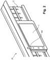
- Figure 1 represents the shelf 3, of a gondola intended to be arranged in a sales area.
- the shelf 3 comprises a shelf support 20.
- the shelf support 20 is, for example, a rail and comprises a receiving section 21 adapted to house the ESLs 4 and the shelf imaging devices 1.
- the ESLs 4 and the shelf imaging device 1 are placed onto the same shelf support 20 (here: the shelf support is a rail).
- the shelf support 20 is installed on one of the edges of the shelf 3.
- the shelf imaging device 1 is mounted on the shelf support 20, and locked in a fixed position on the receiving section 21, with a locking mechanism.
- Such mechanism typically is, or includes, an engaging member such as a pin, for engaging a holding part of the receiving section 21.
- the holding part of the receiving section 21 can be, any holding part able to receive the engaging member for maintaining it in a locked, fixed position.
- the holding part of the receiving section can be for example, discrete holes that can cooperate with a pin from the shelf imaging device 1 serving as an engaging member, for locking the shelf imaging device in the receiving section 21 of the shelf support 20.
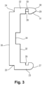
- Figure 2 represents the shelf imaging device 1 with the engaging member 502. This engaging member 502 is movable between a retracted position and an extended position.
- the engaging member 502 is at least partly fitted inside the casing and imaging device 1 is in a free position, detachable from the receiving section 21.
- the engaging member 502 In the extended position the engaging member 502 is in a locking position. In the configuration of figure 2 the engaging member 502 is fitted into a corresponding part of the receiving section 21, so as to lock the shelf imaging device into the receiving section.
- the same receiving section 21 also serves to receive ESLs 4, thus mounted on the same shelf 3 (and the same receiving section 21) as the shelf imaging device 1.
- ESLs 4 can be mounted on the receiving section 21 near, or even adjacent to, the shelf imaging device 1. It can be desired to change the location of the shelf imaging device 1 (e.g. for placing it in front of another viewing area, or for repairing it or for otherwise ensuring its maintenance). Therefore, the locking mechanism should allow unlocking the shelf imaging device from the shelf support 20 for detaching the shelf imaging device 1 from the shelf 3, and relocking the shelf imaging device 1 on the same shelf 3, or onto another shelf 3.
- the locking means of the shelf imaging device should allow a removable locking of the shelf imaging device on the shelf support (more precisely: in the receiving section 21 of the shelf support).
- a shelf imaging device 1 having locking means, which can be actuated (for locking or unlocking the shelf imaging device on a row), through an actuator (i.e. actuating means) of the shelf imaging device 1.
- Such actuator actuates the locking means, to position the locking means either in a locking position where the shelf imaging device 1 can be locked on the receiving section 21, or in a free position where the shelf imaging device is free to be displaced relative to the shelf 3, and to be detached from the shelf 3.
- the actuator is physically accessible to the user, and protrudes from the casing of the imaging device 1 so that the user can manually activate the actuator (e.g. by pushing or pulling it with his/her hand or finger, or with a hand tool).
- Such protruding actuator can be e.g. a pin protruding from the casing of the imaging device.
- the engaging member 502 acts as an actuator, and can be directly activated (pushed or pulled) by the hand of a user.
- a drawback associated with such known shelf imaging devices 1 is that the user has to physically access the actuator and, when the imaging device is positioned adjacent to an ESL 4, the user may have to displace the adjacent ESL 4 before being able to physically access the actuator of the shelf imaging devices, and to trigger actuation of the locking means.
- protruding actuator is a mechanical element can be damaged or broken, because of a rough manipulation or because of shocks with external elements.
- shelf imaging devices which are being mounted on the same shelf support 20 as ESLs 4, are significantly thicker than ESLs 4. This is because the internal elements of the shelf imaging devices include a battery, connectors, and other elements.
- the back faces of shelf imaging devices 1 and ESLs 4 are aligned against shelf support 20 when shelf imaging devices and ESLs 4 are mounted on the same shelf 3, the front faces of shelf imaging devices 1 extend further in the front than the front faces of the ESLs 4.
- the thickness of shelf imaging devices 1 is typically more than 1,5 cm, while the thickness of an ESL 4 is approximately 10 mm.
- an ESL 4 with a specific locking mechanism that can be activated using a magnetic extraction tool.
- This mechanism and extraction tool are, for example, described in the French patent reference FR2765019B1 .
- the implementation of the locking mechanism described in the French patent reference FR2765019B1 in the shelf imaging devices 1 would need a magnetic extraction tool generating a residual magnetism of more than 1.4 Tesla. This amount of residual magnetism could generate drawbacks, such as disruptions on the shelf imaging devices 1 or undesired activation of medical devices, such as pacemakers, worn by the user.
- An object of the invention is a shelf imaging device for a shelf support, wherein the shelf support is installed on a shelf edge and comprises a receiving section configured to receive electronic shelf labels on the shelf support, the receiving section comprising two facing wings extending in a longitudinal direction, one of the two wings has in its medial region a longitudinal groove, the groove has a plurality of holes.
- the shelf imaging device comprises:
- near the front side means that the distance between the front end of the actuator and the front side is between 1 mm and 2 mm, advantageously 1.5 mm.
- near the lateral side means that the distance between the front end of the actuator and the lateral side is between 1 mm and 2 mm, advantageously 1.5mm.
- the magnetic extraction tool used to unlock the shelf imaging device will reduce the disruptions on the shelf imaging device and will reduce the risk of undesirable activations of medical devices, such as pacemakers, worn by the user.
- the same magnetic extraction tool used to unlock the ESL can also be used with the shelf imaging device of the invention.
- the above-defined device can comprise the following advantageous and non-limiting features, taken alone or in any technically feasible combination:
- a shelf system comprising a shelf, preferably for a gondola of a sales area.
- the shelf comprises a shelf support configured to extend along an edge of the shelf, the shelf support comprising a receiving section configured to receive electronic labels on the shelf support and an imaging device, the back side of the imaging device being configured to be removably fitted in the receiving section of the shelf support.
- the receiving section comprises two facing wings extending in a longitudinal direction, one of the two wings has in its medial region a longitudinal groove the groove has a plurality of holes and the engaging member is configured for engaging one of the holes.
- figure 1 represents the shelf 3, of a gondola intended to be arranged in a sales area.
- the shelf 3 comprises a shelf support 20.
- the shelf support 20 is for example a rail and comprises a receiving section 21 adapted to house the ESLs 4 and the shelf imaging devices 1.
- the shelf support 20 is installed on one of the edges of the shelf 3.
- the shelf support 20 is a rail having a hollow section into which ESLs and the shelf imaging device can be engaged and locked.
- shelf support 20 can receive a different number of ESLs 4. It is possible to have up to more than ten ESLs 4 per linear meter of shelf support 20, and hence several thousand, or even tens of thousands of ESLs 4 in one sales area. ESLs 4 can be placed side by side in a continuous series, adjacent to each other, on the shelf support 20.
- each shelf support 20 of the sales area can comprise more than one shelf imaging device 1.
- the compactness of shelf imaging device 1 described hereinafter allows accommodating a plurality of shelf imaging devices 1, for example, regularly spaced in the shelves 3 of the sales area for each viewing ESLs 4 that would be located in front of the shelf imaging device, typically on the other side of the aisle separating two gondolas.
- Figure 4 represents a shelf imaging device 1 of the invention.
- the shelf imaging device 1 comprises a front side 301 and a back side 302.
- the back side 302 is located at the opposite of the front side 301.
- the shelf imaging device 1 comprises a second part 304, which extends from the back side 302 and in the direction of the front side 301.
- the function of this second part 304 is to removably attach the shelf imaging device 1 to the shelf support 20 more precisely to the receiving section 21.
- the second part 304 of the shelf imaging device 1 comprises a lower surface 308 with a longitudinal rib 309. This rib 309 is adapted to be inserted in the groove 26 of the lower wing 23 of the receiving section 21.
- the shelf imaging device 1 comprises a processing unit, a battery and a memory (not shown) and further comprises an optical sensor 305 and a wired data port 307.
- the processing unit, the battery, the memory, the optical sensor 305 and the wired data port 307 are typically mounted on a printed circuit board (not shown) of the shelf imaging device 1.
- the wired data port 307 is, for example, a USB port. This port allows the connection of the shelf imaging device 1 with another device, for example, a computer.
- the optical sensor 305 is configured to acquire images of shelves facing the front side 301 of the shelf imaging device 1.
- the optical sensor 305 can be a camera.
- having the height L1 and width L2 of the shelf imaging device 1 close to the ones of the regular ESLs also allows the top of the shelf imaging devices 1 to be at almost the same level as the top of the ESLs 4 and to not protrude above the top of the ESLs 4. This avoids forming snap points for objects that are moved relative to and near the top of the ESLs 4 and the top of the shelf imaging devices 1.
- the shelf imaging device 1 is shown in cross-section in the vertical plane perpendicular to the front side 301 or the back side 302. This cross-section passes through a locking mechanism 501 represented in figure 6 .
- This locking mechanism 501 allows the locking, and unlocking, of the shelf imaging device 1 to, and from, the receiving section 21.
- the locking mechanism 501 is generally flat, along a plane that is perpendicular to the front side 301. This plane is also parallel to the right lateral side 306 and is near the right lateral side 306. The expression “near the right lateral side” means that the distance between the plane and the right lateral side 306 is between 1 mm and 2 mm, advantageously 1.5mm.
- the locking mechanism 501 is located in a recess 401 of the shelf imaging device 1. This recess 401 extends over at least a portion of the height of the shelf imaging device 1.
- the plane can be parallel to the left lateral side and can be near the left lateral side.
- the expression "near the left lateral side” means that the distance between the plane and the left lateral side is between 1 mm and 2 mm, advantageously 1.5mm.
- the locking mechanism 501 comprises an engaging member 502 for engaging one of the holes 33 of the receiving section 21, to lock the shelf imaging device 1 into the gondola 3.
- This engaging member 502 is, for example, a pin.
- the engaging member 502 is preferably located between 1 cm and 2 cm, most preferably 1.5 cm from the front side 301 of the shelf imaging device 1.
- the locking mechanism 501 also comprises an actuator 503 configured to move the engaging member 502 between a locking position where the shelf imaging device 1 is locked into the receiving section 21 and a free position where the shelf imaging device 1 is free to be displaced relative to the shelf 3.
- the actuator 503 comprises a magnetic element that extends between a front end 503-a, near the front side 301 of the shelf imaging device 1, and a back end 503-b bearing or linked to the engaging member 502.
- the front end 503-a is the part of the actuator 503 the closest to the front side 301 of the shelf imaging device 1.
- the locking mechanism 501 comprises a guiding element 504 acting with a spring 402, for example a spiral spring, to urge upwardly the locking mechanism 501 and more precisely the engaging member 502, to project the engaging member 502 through an opening 403 of the shelf imaging device 1, and to place the engaging member 502 within one of the holes 33 of the receiving section 21.
- a spring 402 for example a spiral spring
- the locking mechanism 501 comprises a rigid link 505 linking together the actuator 503, the guiding element 504 and the engaging member 502.
- the actuator 503 and the guiding element 504 form two parallel branches of the locking mechanism 501.
- the actuator 503 is located near the front side 301 of the shelf imaging device 1 and the guiding element 504 is located near the back side 302 of the shelf imaging device 1.
- the actuator 503 can be constituted of a flat element for example a magnetic metal plate.
- the actuator 503 can have a thickness L503-1 comprised between 0.8 and 1.2mm preferably 1mm, a width L503-2 comprised between 0.5cm and 1.5cm advantageously 0.9cm and a length L503-3 comprised between 2 cm and 3 cm advantageously 2.5 cm.
- This magnetic metal is a standard magnetic metal for example steel or nickel alloy.
- the front end 503-a of the actuator 503 is located near the front side 301 of the shelf imaging device1.
- Located near the front side 301 means in the present specification that the distance between the front end 503-a of the actuator 503 and the front side 301 is between 1 mm and 2 mm, advantageously 1.5mm.
- the front end 503-a of the actuator 503 can also be located near one of the lateral sides (near the right lateral side 306 in figure 5 ) of the shelf imaging device 1.
- Located near the lateral side means that the distance between the lateral side and the front end 503-a is between 1 and 2 mm, advantageously 1.5mm.
- the distance, comprised between 1 and 2mm, separating the front end 503-a of the actuator 503 and the front side 301 and/or lateral side 306 of the shelf imaging device 1, allows the use of extraction tool having a magnet with a residual magnetism of less than 1,4 Tesla and advantageously comprised between 1.29 Tesla and 1.32 Tesla. More precisely, a residual magnetism of 1.4 Tesla applied in the vicinity, for example at less than 1.5mm, of the front side 301 of the shelf imaging device 1 is enough to move the actuator 503 downside and retract the engaging member 502 in the shelf imaging device 1.
- the extraction tool usable with the locking mechanism 501 of the invention will not generate drawbacks, such as disruptions on the shelf imaging devices 1 or undesired activation of medical devices, such as pacemakers, worn by the user.
- the locking mechanism 501 of the invention can be used with the extraction tool used to unlock the ESL and described in the French patent reference FR2765019B1 .
- the locking mechanism 501 of the invention can be used with an extraction tool having a magnet with a residual magnetism of less than 1,4 Tesla and advantageously comprised between 1,29 Tesla and 1,32 Tesla.
- the engaging member 502 for example the pin
- the actuator 503 and the guiding element 504 are realized as separated elements and attached together, by example by welding.
- the engaging member 502 is applied to the inner chamfered profile 29 which presses it inwardly of the shelf imaging device 1 by compressing the spring 402.
- the engaging member 502 penetrates, under the action of the spring 402, the groove 28 of the upper wing 22 of the support 20.
- the shelf imaging device 1 is thus in the operative position.
- the shelf imaging device 1 is then moved along the shelf support 20, by sliding, until the engaging member 502 penetrates, under the action of the spring 28, one of the holes 33. The shelf imaging device 1 is then in the locked position.
- the extraction tool will be used. This extraction tool is used by approaching the extraction tool to the shelf imaging device 1 by its front side 301.
- the extraction tool comprises a housing for example of plastic material and a magnetic circuit constituted a magnet and a ferromagnetic core.
Landscapes
- Physics & Mathematics (AREA)
- General Physics & Mathematics (AREA)
- Engineering & Computer Science (AREA)
- Theoretical Computer Science (AREA)
- Studio Devices (AREA)
- Magnetic Resonance Imaging Apparatus (AREA)
- Warehouses Or Storage Devices (AREA)
Claims (7)
- Regalbildgebungsvorrichtung (1) für eine Regalstütze (20), wobei die Regalstütze (20) an einem Regalrand eingerichtet ist und einen Aufnahmeabschnitt (21) umfasst, der dazu ausgestaltet ist, elektronische Regaletiketten (4) an der Regalstütze (20) aufzunehmen, wobei der Aufnahmeabschnitt (21) zwei zugewandte Flügel (22, 23) umfasst, die sich in einer Längsrichtung erstrecken, einer der zwei Flügel (22, 23) in seiner medialen Region eine Längsnut (26, 28) aufweist, wobei die Nut eine Vielzahl von Löchern (33) aufweist, wobei die Regalbildgebungsvorrichtung (1) umfasst:• eine Rückseite (302), die dazu ausgestaltet ist, abnehmbar in dem Aufnahmeabschnitt (21) eingepasst zu sein,• eine Vorderseite (301), die der Rückseite (302) entgegengesetzt ist,• einen optischen Sensor (305), der dazu ausgestaltet ist, ein Bild von Regalen zu erfassen, die der Vorderseite (301) zugewandt sind,• ein Eingriffselement (502) für den Eingriff des Aufnahmeabschnitts (21), um die Regalbildgebungsvorrichtung (1) in die Regalstütze (20) zu verriegeln, wenn das Eingriffselement (502) von der Regalbildgebungsvorrichtung (1) hervorsteht und mit einem der Löcher ineinandergreift, an oder hinter der Rückseite (302) der Regalbildgebungsvorrichtung (1),dadurch gekennzeichnet, dass sie ferner umfasst:• ein Führungselement (504) und eine Feder (402), wobei das Führungselement (504) und die Feder (402) zusammen dazu ausgestaltet sind, das Eingriffselement (502) nach oben zu drängen, um durch eine Öffnung (403) der Regalbildgebungsvorrichtung (1) hervorzustehen,• ein Betätigungsorgan (503), das dazu ausgestaltet ist, das Eingriffselement (502) zwischen einer Verriegelungsposition, in der die Regalbildgebungsvorrichtung (1) in die Regalstütze (20) verriegelt ist, und einer freien Position zu bewegen, in der die Regalbildgebungsvorrichtung (1) frei ist, in Bezug auf die Regalstütze (20) verlagert zu werden, wobei das Betätigungsorgan (503) ein magnetisches Element umfasst, das sich zwischen einem vorderen Ende (503-a), das sich nahe an der Vorderseite (301) und/oder nahe an einer seitlichen Seite der Regalbildgebungsvorrichtung (1) befindet, und einem hinteren Ende (503-b) erstreckt, das mit dem Eingriffselement (502) verbunden ist, und• eine Verbindung (505), die das Führungselement (504), das Eingriffselement (502) und das Betätigungsorgan (503) miteinander verbindet.
- Regalbildgebungsvorrichtung (1) nach Anspruch 1, wobei das magnetische Element des Betätigungsorgans (503) eine Metallplatte ist, die sich entlang einer Ebene senkrecht zur Vorderseite (301) parallel zur seitlichen Seite und nahe an der seitlichen Seite erstreckt, wobei eine Länge (L503-3) der Metallplatte zwischen 2 cm und 3 cm, vorzugsweise 2,5 cm, beträgt und/oder eine Breite (L503-2) der Metallplatte zwischen 0,5 cm und 1,5 cm, vorzugsweise 0,9 cm, beträgt, und/oder eine Dicke (L503-1) der Metallplatte zwischen 0,8 mm und 1,2 mm, vorzugsweise 1 mm, beträgt.
- Regalbildgebungsvorrichtung (1) nach Anspruch 1 oder 2, wobei das vordere Ende (503-a) sich zwischen 1 mm und 2 mm, vorzugsweise 1,5 mm, von der Vorderseite (301) der Regalbildgebungsvorrichtung (1) befindet.
- Regalbildgebungsvorrichtung (1) nach einem der Ansprüche 1 bis 3, wobei das vordere Ende (503-a) sich zwischen 1 mm und 2 mm, vorzugsweise 1,5 mm, von einer seitlichen Seite (306) der Regalbildgebungsvorrichtung (1) befindet.
- Regalbildgebungsvorrichtung (1) nach einem der Ansprüche 1 bis 4, wobei ein Abstand zwischen dem Eingriffselement (502) und der Vorderseite (301) der Regalbildgebungsvorrichtung (1) zwischen 1 cm und 2 cm, vorzugsweise 1,5 mm, beträgt.
- Regalbildgebungsvorrichtung (1) nach einem der Ansprüche 1 bis 5, wobei das Führungselement (504), das Eingriffselement (502) und das Betätigungsorgan (503) ein einziges Teil bilden.
- Regalsystem, das ein Regal (3), vorzugsweise für eine Gondel eines Verkaufsbereichs, umfasst, wobei das Regal (3) umfasst:• eine Regalstütze (20), die dazu ausgestaltet ist, sich entlang eines Randes des Regals (3) zu erstrecken, wobei die Regalstütze (20) einen Aufnahmeabschnitt (21) umfasst, der dazu ausgestaltet ist, elektronische Etiketten (4) an der Regalstütze aufzunehmen, und• eine Bildgebungsvorrichtung (1) nach einem der Ansprüche 1 bis 6, wobei die Rückseite (11) der Bildgebungsvorrichtung (1) dazu ausgestaltet ist, abnehmbar in dem Aufnahmeabschnitt (21) der Regalstütze (20) eingepasst zu sein.
Applications Claiming Priority (2)
| Application Number | Priority Date | Filing Date | Title |
|---|---|---|---|
| FR2104841A FR3122764B1 (fr) | 2021-05-07 | 2021-05-07 | Dispositif d’imagerie d’étagère pour un support d’étagère et un système d’étagère comprenant le dispositif d’imagerie d’étagère |
| PCT/EP2022/062259 WO2022234072A1 (en) | 2021-05-07 | 2022-05-06 | Shelf imaging device for a shelf support and shelf system comprising the shelf imaging device |
Publications (4)
| Publication Number | Publication Date |
|---|---|
| EP4334928A1 EP4334928A1 (de) | 2024-03-13 |
| EP4334928C0 EP4334928C0 (de) | 2025-06-25 |
| EP4334928B1 true EP4334928B1 (de) | 2025-06-25 |
| EP4334928B8 EP4334928B8 (de) | 2025-08-06 |
Family
ID=76523141
Family Applications (1)
| Application Number | Title | Priority Date | Filing Date |
|---|---|---|---|
| EP22727900.7A Active EP4334928B8 (de) | 2021-05-07 | 2022-05-06 | Regalbildgebungsvorrichtung für eine regalstütze und regalsystem mit der regalbildgebungsvorrichtung |
Country Status (6)
| Country | Link |
|---|---|
| US (1) | US12444326B2 (de) |
| EP (1) | EP4334928B8 (de) |
| CN (1) | CN117730360A (de) |
| AU (1) | AU2022269298A1 (de) |
| FR (2) | FR3122764B1 (de) |
| WO (1) | WO2022234072A1 (de) |
Families Citing this family (1)
| Publication number | Priority date | Publication date | Assignee | Title |
|---|---|---|---|---|
| US20240428709A1 (en) * | 2023-06-20 | 2024-12-26 | Vusiongroup Gmbh | Fastening element for fastening for fixing a display unit to a support device |
Family Cites Families (15)
| Publication number | Priority date | Publication date | Assignee | Title |
|---|---|---|---|---|
| FR2765019B1 (fr) * | 1997-06-18 | 1999-10-15 | Label 41 | Systeme d'etiquetage electronique |
| FR2832840B1 (fr) * | 2001-11-27 | 2003-12-26 | Store Electronic Systems Techn | Systeme d'etiquetage electronique destine a etre porte par la traverse d'un presentoir a broche |
| KR100982268B1 (ko) * | 2008-10-15 | 2010-09-15 | 삼성전기주식회사 | 가격 표시 장치 |
| US9474177B2 (en) * | 2012-04-26 | 2016-10-18 | Teraoka Seiko Co., Ltd. | Wireless display mount, wireless display mount apparatus, and wireless display system |
| WO2016052382A1 (ja) * | 2014-09-30 | 2016-04-07 | 日本電気株式会社 | 情報処理装置、棚札管理システム、制御方法、及びプログラム |
| FR3048806B1 (fr) * | 2016-03-08 | 2019-07-05 | Store Electronic Systems | Systeme d'affichage d'information dans une surface de vente |
| US11636783B2 (en) * | 2016-12-28 | 2023-04-25 | Opticon Sensors Europe B.V. | Electronic shelf label system |
| FR3071341B1 (fr) * | 2017-09-19 | 2019-09-20 | Ses-Imagotag | Procede mis en oeuvre par camera de controle de disposition d'articles pour des etageres equipees d'etiquettes electroniques de gondole |
| FR3099020B1 (fr) * | 2019-07-15 | 2022-01-14 | Ses Imagotag | Dispositif d’imagerie pour un support d’étagère et système d’étagère comprenant le dispositif d’imagerie |
| KR102186945B1 (ko) * | 2019-09-19 | 2020-12-04 | 주식회사 라인어스 | 전자 라벨 홀더 |
| WO2022096117A1 (de) * | 2020-11-05 | 2022-05-12 | Ses-Imagotag Gmbh | Elektronische anzeigevorrichtung zur befestigung an einer regalschiene |
| JP2024514407A (ja) * | 2021-03-09 | 2024-04-02 | エスエーエス-イマーゴタグ・ゲゼルシャフト・ミト・ベシュレンクテル・ハフツング | 棚レールにある装置の位置の特定 |
| US12380814B2 (en) * | 2021-04-13 | 2025-08-05 | Vusiongroup Gmbh | Support device for supporting an electronic device within an accommodating space of the support device |
| FR3122761B1 (fr) * | 2021-05-07 | 2024-07-19 | Captana Gmbh | Système et procédé de gestion des stocks avec activation synchronisée de dispositifs de rayons et de capteurs |
| EP4386723A4 (de) * | 2021-08-09 | 2025-05-14 | Hanshow Technology Co., Ltd. | Führungsschiene zur installation eines ultradünnen elektronischen epd-preisschilds |
-
2021
- 2021-05-07 FR FR2104841A patent/FR3122764B1/fr active Active
-
2022
- 2022-05-06 AU AU2022269298A patent/AU2022269298A1/en active Pending
- 2022-05-06 WO PCT/EP2022/062259 patent/WO2022234072A1/en not_active Ceased
- 2022-05-06 US US18/289,662 patent/US12444326B2/en active Active
- 2022-05-06 CN CN202280047993.0A patent/CN117730360A/zh active Pending
- 2022-05-06 EP EP22727900.7A patent/EP4334928B8/de active Active
-
2024
- 2024-05-28 FR FR2405456A patent/FR3149122A1/fr active Pending
Also Published As
| Publication number | Publication date |
|---|---|
| EP4334928A1 (de) | 2024-03-13 |
| EP4334928C0 (de) | 2025-06-25 |
| US20240242639A1 (en) | 2024-07-18 |
| FR3149122A1 (fr) | 2024-11-29 |
| FR3122764B1 (fr) | 2024-06-28 |
| EP4334928B8 (de) | 2025-08-06 |
| US12444326B2 (en) | 2025-10-14 |
| AU2022269298A1 (en) | 2023-11-23 |
| CN117730360A (zh) | 2024-03-19 |
| WO2022234072A1 (en) | 2022-11-10 |
| FR3122764A1 (fr) | 2022-11-11 |
Similar Documents
| Publication | Publication Date | Title |
|---|---|---|
| KR101004862B1 (ko) | 전자 선반 라벨 | |
| KR100982268B1 (ko) | 가격 표시 장치 | |
| JP6826125B2 (ja) | 販売エリアにおける情報ディスプレイシステム | |
| US8307995B2 (en) | Theft deterrent system | |
| PL189737B1 (pl) | System etykietowania elektronicznego | |
| EP4334928B1 (de) | Regalbildgebungsvorrichtung für eine regalstütze und regalsystem mit der regalbildgebungsvorrichtung | |
| WO1995014841A1 (en) | Anti-theft box | |
| EP3032009A1 (de) | Sicherheitsvorrichtung zur verriegelung einer warenaufhängestange an eine präsentationswandplatte | |
| BR112012023676A2 (pt) | sistema de armazenamento para suprir artigos | |
| EP2919212B1 (de) | Sicherheitsverschluss mit integrierter Sperrvorrichtung | |
| US9353552B1 (en) | Anti-theft device for merchandise displays | |
| CN108701288B (zh) | 库存控制系统和控制库存的方法 | |
| SE534425C2 (sv) | Elektronsik hylletikett och hållare innefattande låsmekanism, samt låsmekanism | |
| JP5547179B2 (ja) | 電子棚札 | |
| KR101462791B1 (ko) | 전자 상품 표시기 어셈블리 | |
| WO2012112115A1 (en) | Adapter | |
| HK40104297A (en) | Shelf imaging device for a shelf support and shelf system comprising the shelf imaging device | |
| HK40104297B (en) | Shelf imaging device for a shelf support and shelf system comprising the shelf imaging device | |
| EP2215934A2 (de) | Feststellvorrichtung und Etiketthalterbefestigung für Warenauslagehaken | |
| US10497290B2 (en) | Protective element of an electronic price label and electronic price label arrangement | |
| US11426013B2 (en) | Product display pusher system and associated retail fixture system | |
| EP2776917B1 (de) | Indikatorvorrichtung | |
| HUP0203694A2 (hu) | Bizonyos nemionos felületaktív anyagot tartalmazó új peszticid és/vagy növekedésszabályozó készítmények | |
| KR20140141324A (ko) | 전자태그의 리모컨 | |
| EP4066233B1 (de) | Stützanordnung für eine in einer einzelhandelsumgebugn verwendeten einheit |
Legal Events
| Date | Code | Title | Description |
|---|---|---|---|
| STAA | Information on the status of an ep patent application or granted ep patent |
Free format text: STATUS: UNKNOWN |
|
| STAA | Information on the status of an ep patent application or granted ep patent |
Free format text: STATUS: THE INTERNATIONAL PUBLICATION HAS BEEN MADE |
|
| PUAI | Public reference made under article 153(3) epc to a published international application that has entered the european phase |
Free format text: ORIGINAL CODE: 0009012 |
|
| STAA | Information on the status of an ep patent application or granted ep patent |
Free format text: STATUS: REQUEST FOR EXAMINATION WAS MADE |
|
| 17P | Request for examination filed |
Effective date: 20231201 |
|
| AK | Designated contracting states |
Kind code of ref document: A1 Designated state(s): AL AT BE BG CH CY CZ DE DK EE ES FI FR GB GR HR HU IE IS IT LI LT LU LV MC MK MT NL NO PL PT RO RS SE SI SK SM TR |
|
| REG | Reference to a national code |
Ref country code: HK Ref legal event code: DE Ref document number: 40104297 Country of ref document: HK |
|
| DAV | Request for validation of the european patent (deleted) | ||
| DAX | Request for extension of the european patent (deleted) | ||
| GRAP | Despatch of communication of intention to grant a patent |
Free format text: ORIGINAL CODE: EPIDOSNIGR1 |
|
| STAA | Information on the status of an ep patent application or granted ep patent |
Free format text: STATUS: GRANT OF PATENT IS INTENDED |
|
| GRAJ | Information related to disapproval of communication of intention to grant by the applicant or resumption of examination proceedings by the epo deleted |
Free format text: ORIGINAL CODE: EPIDOSDIGR1 |
|
| STAA | Information on the status of an ep patent application or granted ep patent |
Free format text: STATUS: REQUEST FOR EXAMINATION WAS MADE |
|
| INTG | Intention to grant announced |
Effective date: 20241126 |
|
| INTG | Intention to grant announced |
Effective date: 20241203 |
|
| GRAP | Despatch of communication of intention to grant a patent |
Free format text: ORIGINAL CODE: EPIDOSNIGR1 |
|
| STAA | Information on the status of an ep patent application or granted ep patent |
Free format text: STATUS: GRANT OF PATENT IS INTENDED |
|
| INTG | Intention to grant announced |
Effective date: 20241210 |
|
| INTC | Intention to grant announced (deleted) | ||
| GRAJ | Information related to disapproval of communication of intention to grant by the applicant or resumption of examination proceedings by the epo deleted |
Free format text: ORIGINAL CODE: EPIDOSDIGR1 |
|
| GRAP | Despatch of communication of intention to grant a patent |
Free format text: ORIGINAL CODE: EPIDOSNIGR1 |
|
| GRAJ | Information related to disapproval of communication of intention to grant by the applicant or resumption of examination proceedings by the epo deleted |
Free format text: ORIGINAL CODE: EPIDOSDIGR1 |
|
| INTG | Intention to grant announced |
Effective date: 20250103 |
|
| STAA | Information on the status of an ep patent application or granted ep patent |
Free format text: STATUS: REQUEST FOR EXAMINATION WAS MADE |
|
| GRAP | Despatch of communication of intention to grant a patent |
Free format text: ORIGINAL CODE: EPIDOSNIGR1 |
|
| STAA | Information on the status of an ep patent application or granted ep patent |
Free format text: STATUS: GRANT OF PATENT IS INTENDED |
|
| GRAJ | Information related to disapproval of communication of intention to grant by the applicant or resumption of examination proceedings by the epo deleted |
Free format text: ORIGINAL CODE: EPIDOSDIGR1 |
|
| GRAP | Despatch of communication of intention to grant a patent |
Free format text: ORIGINAL CODE: EPIDOSNIGR1 |
|
| STAA | Information on the status of an ep patent application or granted ep patent |
Free format text: STATUS: REQUEST FOR EXAMINATION WAS MADE |
|
| GRAJ | Information related to disapproval of communication of intention to grant by the applicant or resumption of examination proceedings by the epo deleted |
Free format text: ORIGINAL CODE: EPIDOSDIGR1 |
|
| GRAP | Despatch of communication of intention to grant a patent |
Free format text: ORIGINAL CODE: EPIDOSNIGR1 |
|
| STAA | Information on the status of an ep patent application or granted ep patent |
Free format text: STATUS: GRANT OF PATENT IS INTENDED |
|
| INTG | Intention to grant announced |
Effective date: 20250127 |
|
| INTG | Intention to grant announced |
Effective date: 20250203 |
|
| INTC | Intention to grant announced (deleted) | ||
| INTG | Intention to grant announced |
Effective date: 20250224 |
|
| GRAS | Grant fee paid |
Free format text: ORIGINAL CODE: EPIDOSNIGR3 |
|
| GRAA | (expected) grant |
Free format text: ORIGINAL CODE: 0009210 |
|
| STAA | Information on the status of an ep patent application or granted ep patent |
Free format text: STATUS: THE PATENT HAS BEEN GRANTED |
|
| AK | Designated contracting states |
Kind code of ref document: B1 Designated state(s): AL AT BE BG CH CY CZ DE DK EE ES FI FR GB GR HR HU IE IS IT LI LT LU LV MC MK MT NL NO PL PT RO RS SE SI SK SM TR |
|
| REG | Reference to a national code |
Ref country code: GB Ref legal event code: FG4D |
|
| REG | Reference to a national code |
Ref country code: CH Ref legal event code: EP |
|
| REG | Reference to a national code |
Ref country code: DE Ref legal event code: R096 Ref document number: 602022016475 Country of ref document: DE |
|
| REG | Reference to a national code |
Ref country code: DE Ref legal event code: R081 Ref document number: 602022016475 Country of ref document: DE Owner name: VUSIONGROUP DEUTSCHLAND GMBH, DE Free format text: FORMER OWNER: ANMELDERANGABEN UNKLAR / UNVOLLSTAENDIG, 80297 MUENCHEN, DE Ref country code: CH Ref legal event code: EP Ref country code: CH Ref legal event code: PK Free format text: BERICHTIGUNG B8 |
|
| REG | Reference to a national code |
Ref country code: IE Ref legal event code: FG4D |
|
| RAP4 | Party data changed (patent owner data changed or rights of a patent transferred) |
Owner name: VUSIONGROUP DEUTSCHLAND GMBH |
|
| U01 | Request for unitary effect filed |
Effective date: 20250709 |
|
| U07 | Unitary effect registered |
Designated state(s): AT BE BG DE DK EE FI FR IT LT LU LV MT NL PT RO SE SI Effective date: 20250717 |
|
| PG25 | Lapsed in a contracting state [announced via postgrant information from national office to epo] |
Ref country code: GR Free format text: LAPSE BECAUSE OF FAILURE TO SUBMIT A TRANSLATION OF THE DESCRIPTION OR TO PAY THE FEE WITHIN THE PRESCRIBED TIME-LIMIT Effective date: 20250926 Ref country code: NO Free format text: LAPSE BECAUSE OF FAILURE TO SUBMIT A TRANSLATION OF THE DESCRIPTION OR TO PAY THE FEE WITHIN THE PRESCRIBED TIME-LIMIT Effective date: 20250925 |
|
| PG25 | Lapsed in a contracting state [announced via postgrant information from national office to epo] |
Ref country code: HR Free format text: LAPSE BECAUSE OF FAILURE TO SUBMIT A TRANSLATION OF THE DESCRIPTION OR TO PAY THE FEE WITHIN THE PRESCRIBED TIME-LIMIT Effective date: 20250625 |
|
| PG25 | Lapsed in a contracting state [announced via postgrant information from national office to epo] |
Ref country code: RS Free format text: LAPSE BECAUSE OF FAILURE TO SUBMIT A TRANSLATION OF THE DESCRIPTION OR TO PAY THE FEE WITHIN THE PRESCRIBED TIME-LIMIT Effective date: 20250925 |
|
| PG25 | Lapsed in a contracting state [announced via postgrant information from national office to epo] |
Ref country code: IS Free format text: LAPSE BECAUSE OF FAILURE TO SUBMIT A TRANSLATION OF THE DESCRIPTION OR TO PAY THE FEE WITHIN THE PRESCRIBED TIME-LIMIT Effective date: 20251025 |
|
| PG25 | Lapsed in a contracting state [announced via postgrant information from national office to epo] |
Ref country code: SM Free format text: LAPSE BECAUSE OF FAILURE TO SUBMIT A TRANSLATION OF THE DESCRIPTION OR TO PAY THE FEE WITHIN THE PRESCRIBED TIME-LIMIT Effective date: 20250625 |
|
| PG25 | Lapsed in a contracting state [announced via postgrant information from national office to epo] |
Ref country code: CZ Free format text: LAPSE BECAUSE OF FAILURE TO SUBMIT A TRANSLATION OF THE DESCRIPTION OR TO PAY THE FEE WITHIN THE PRESCRIBED TIME-LIMIT Effective date: 20250625 |
|
| PG25 | Lapsed in a contracting state [announced via postgrant information from national office to epo] |
Ref country code: PL Free format text: LAPSE BECAUSE OF FAILURE TO SUBMIT A TRANSLATION OF THE DESCRIPTION OR TO PAY THE FEE WITHIN THE PRESCRIBED TIME-LIMIT Effective date: 20250625 |
|
| PG25 | Lapsed in a contracting state [announced via postgrant information from national office to epo] |
Ref country code: SK Free format text: LAPSE BECAUSE OF FAILURE TO SUBMIT A TRANSLATION OF THE DESCRIPTION OR TO PAY THE FEE WITHIN THE PRESCRIBED TIME-LIMIT Effective date: 20250625 |
|
| PG25 | Lapsed in a contracting state [announced via postgrant information from national office to epo] |
Ref country code: ES Free format text: LAPSE BECAUSE OF FAILURE TO SUBMIT A TRANSLATION OF THE DESCRIPTION OR TO PAY THE FEE WITHIN THE PRESCRIBED TIME-LIMIT Effective date: 20250625 |