EP4334050B1 - Verfahren zum walzen eines ringförmigen walzguts mit einem offenen zylindrischen querschnitt in einer ringwalzmaschine sowie ringwalzmaschine zur durchführung des verfahrens - Google Patents
Verfahren zum walzen eines ringförmigen walzguts mit einem offenen zylindrischen querschnitt in einer ringwalzmaschine sowie ringwalzmaschine zur durchführung des verfahrens Download PDFInfo
- Publication number
- EP4334050B1 EP4334050B1 EP22727768.8A EP22727768A EP4334050B1 EP 4334050 B1 EP4334050 B1 EP 4334050B1 EP 22727768 A EP22727768 A EP 22727768A EP 4334050 B1 EP4334050 B1 EP 4334050B1
- Authority
- EP
- European Patent Office
- Prior art keywords
- rolling
- inductor
- ring
- rolling material
- rolling machine
- Prior art date
- Legal status (The legal status is an assumption and is not a legal conclusion. Google has not performed a legal analysis and makes no representation as to the accuracy of the status listed.)
- Active
Links
Images


Classifications
-
- B—PERFORMING OPERATIONS; TRANSPORTING
- B21—MECHANICAL METAL-WORKING WITHOUT ESSENTIALLY REMOVING MATERIAL; PUNCHING METAL
- B21H—MAKING PARTICULAR METAL OBJECTS BY ROLLING, e.g. SCREWS, WHEELS, RINGS, BARRELS, BALLS
- B21H1/00—Making articles shaped as bodies of revolution
- B21H1/06—Making articles shaped as bodies of revolution rings of restricted axial length
Definitions
- the invention relates to a method for rolling an annular rolling stock with an open cylindrical cross-section in a ring rolling machine with inductive heating of the rolling stock during the rolling process.
- the invention particularly relates to a method for producing metal rings with rectangular or profiled cross-sections from various types of steel, as well as special alloys such as titanium and nickel-based alloys, copper alloys and aluminum alloys by rolling.
- the inductive heating of rolling stock during the rolling process when rolling an annular rolling stock is basically known, for example from US 2012/0279268 A1
- This publication relates to a method for forging a ring-shaped workpiece while simultaneously electrically heating the workpiece by means of induction.
- the method comprises partially or completely enclosing the workpiece with a closed or C-shaped magnetizable core, which is wound with a coil that is supplied with a low-frequency alternating current in the range of approximately 1000 Hz or less.
- This method is cumbersome and expensive, not least because of the necessary enclosure of the workpiece with the magnetic or magnetizable core.
- the temperature control during rolling is intended to counteract heat losses, particularly through radiation. As the size of the rolled material increases or the diameter of the ring increases during rolling, the surface area increases, which leads to increasing heat losses. According to the invention, these temperature losses are to be compensated.
- the method comprises the use of at least one inductor which is held at a predetermined and constant coupling distance relative to the rolling stock and is guided or entrained during the forming process in accordance with the dimensional change of the rolling stock, wherein an alternating magnetic field, preferably with a frequency between 4 and 10 kHz, is coupled directly into the rolling stock by means of the inductor.
- Enclosing the rolling stock or partially enclosing the rolling stock with an electrically conductive core is not provided for and is not necessary in the method according to the invention. Instead, at least one inductor is positioned at a relatively small distance from the rolling stock and held there during the rolling process. This distance, which is dimensioned such that it induces an alternating magnetic field in the rolling stock and a The distance which enables the rolling stock to be heated accordingly is referred to in the present application as the coupling distance.
- the inductor is positioned and held on the outer circumference of the rolling stock during the rolling process.
- the rolling stock in the form of a cylindrical ring that is open on both sides and preferably has a profiled cross-section undergoes dimensional changes during the forming process.
- the diameter of the ring-shaped rolling stock increases, the height of the ring decreases and its width also decreases. Accordingly, the invention provides for the inductor to be adjusted according to the dimensional change of the rolling stock with a constant coupling distance to the rolling stock.
- the inductor can be attached to a support arm which can follow the increase in diameter of the ring-shaped rolling stock, for example with a rolling stand for axial rolling of the ring rolling machine.
- the support arm can be attached to the rolling stand, for example.
- the inductor is controlled by means of at least one manipulator with at least one linear movement and/or one rotary movement on a movement axis. This can be accomplished in particular by means of a multi-axis industrial robot on which at least one inductor can be arranged.
- an actual distance of the inductor to the rolling stock is detected by sensors during the rolling process and the coupling distance is automatically regulated as a target distance depending on the actual distance.
- a regulation can be carried out with a The control unit provided for the ring rolling machine can be used. Alternatively, the control can be carried out using a separate control unit.
- the sensory detection of the actual distance of the inductor from the rolling stock is carried out tactilely by means of at least two sensing rollers or spacers, whereby the distance of the inductor from the rolling stock is predetermined via the spacers resting on the rolling stock during the rolling process.
- a contactless detection of the actual distance can be provided by means of at least one optical sensor.
- an inductive coupling with at least one inductor in the direction of rotation of the rolling stock takes place at least in front of a main roll or an axial roll arrangement of the ring rolling machine, so that the rolling stock is heated immediately before the main roll or the axial roll arrangement engages the rolling stock.
- the invention is to be understood in such a way that the inductor or several inductors can be provided at any point on the ring rolling machine on the circumference of the rolling stock.
- At least two inductors are positioned on the circumference of the rolling stock, for example in the direction of rotation of the rolling stock at least in front of a main roll and in front of an axial roll arrangement of the ring rolling machine if this is designed as a radial-axial ring rolling machine.
- the inductor is guided on a support arm which preferably has at least two degrees of freedom, preferably three degrees of freedom.
- the inductor is preferably guided so as to be linearly displaceable as well as rotatable.
- the inductor is moved along with the increasing radius and with the displacement of the axis of rotation of the cylindrical rolling stock during the rolling process.
- a further aspect of the invention relates to a ring rolling machine, which is preferably designed to carry out the method described above.
- the ring rolling machine is preferably designed as a radial or radial-axial ring rolling machine and comprises at least one driven main roller and at least one mandrel roller, preferably also at least two axial rollers, preferably as tapered rollers, and means for centering an annular rolling stock.
- the ring rolling machine according to the invention is characterized by at least one inductor, which can be positioned on an outer circumference of the rolling stock at a predetermined coupling distance from the rolling stock during the rolling process and can be adjusted in accordance with the dimensional change of the rolling stock in order to maintain a constant coupling distance, wherein an alternating magnetic field, preferably with a frequency between 4 and 10 kHz, can be induced in the rolling stock using the inductor.
- At least one of the axial rollers can be designed as a driven roller.
- the ring rolling machine can be designed as a radial ring rolling machine or as a radial-axial ring rolling machine. Only in the latter case would the ring rolling machine according to the invention comprise axial rollers.
- pivoting arms with centering rollers can be provided, which rest against the outer circumference of the rolling stock during the rolling process.
- the inductor is mounted on a support arm of a ring rolling machine divided into at least two degrees of freedom, preferably three degrees of freedom movable manipulator.
- the inductor is arranged at least in front of the main roll or the axial rolls in the direction of rotation of the rolling stock.
- an inductor is arranged in front of the main roll and the axial rolls in the direction of rotation of the rolling stock.
- the invention is to be understood in such a way that more than two inductors can be provided on the circumference of the rolling stock.
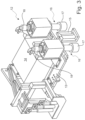
- the ring rolling machine 1 shown in the figures comprises a driven main roll 2 and a rolling table 4.
- the rolling stock, designated 5, is designed as a closed ring or as a cylinder open on both sides.
- the rolling stock 5 has a rectangular cross-sectional profile and rests on the rolling table 4.
- the rolling stock 5 is rolled between the main roll 2 and the mandrel roll 3 in the Clockwise, reducing the wall thickness radially and simultaneously reducing the height axially.
- the rolled stock 5 is centered in the ring rolling machine 1 by means of centering rollers 7 attached to swivel arms 6.
- the rolled stock 5 is rolled axially by means of two axial rollers 8.
- the axial rollers 8 are designed as tapered rollers and are mounted in an axial stand 10.
- the axial stand 10 can be moved or adjusted in relation to the center of the rolled stock 5, which shifts during the rolling process as a result of the increase in the radius, and specifically radially in relation to the rolled stock 5.
- a support arm 11 is attached to the axial stand 10, at the end of which an inductor 12 is arranged, which is directed radially inwards with respect to the rolling stock 5.
- the inductor 12 can alternatively be attached to an articulated arm of an industrial robot which is set up on the circumference of the ring rolling machine 1.
- the inductor 12 comprises a transformer unit 14 arranged on a base plate 13 and an induction coil 15, as can be seen from Figure 3 can be seen.
- the transformer unit 14 is connected to a capacitor cabinet (not shown) via air and/or water-cooled cables and ensures the electrical adaptation of the induction voltage to the output voltage of a frequency converter.
- the frequency converter operates in a frequency range between 4 and 10 kHz.
- Two spacers 16 are also arranged on the base plate 13, between which the induction coil 15 is located.
- the spacers 16 are designed as feeler rollers extending parallel to the axis of rotation of the rolling stock 5, the roller heads 17 of which are held in engagement with the rolling stock 5 during the rolling process.
- the spacers 16 are water-cooled. Coolant connections 18 are provided for the previously mentioned spacers 16 through which coolant flows.
- the induction coil, the transformer unit and the spacers 16 are arranged on the base plate so that they can be adjusted both linearly and rotatably. Since, as described above, the radius of the rolling stock 5 increases during the rolling process and the distance between the induction coil 15 and the rolling stock 5 would consequently increase, a further linear adjustment between the spacers 16 and the induction coil 15 is provided. The adjustability ensures that the distance between the induction coil 15 and the rolling stock can be kept constant.
- the support arm 11 with the axial stand 10 can also be moved radially in relation to the rolling stock.
- the height of the rolling stock 5 will decrease on the one hand, and the diameter of the rolling stock 5 will increase on the other, so that the support arm 11 must be adjusted radially at least in relation to the rolling stock 5.
- the induction coil 15 shown has an approximately L-shaped cross-sectional profile that extends under part of the underside of the annular rolling stock 5. According to the invention, the induction coil can also have a different geometry. It is not necessary for the induction coil 15 to extend under the underside of the annular rolling stock 5.
Landscapes
- Engineering & Computer Science (AREA)
- Mechanical Engineering (AREA)
- General Induction Heating (AREA)
- Metal Rolling (AREA)
- Rolling Contact Bearings (AREA)
Description
- Die Erfindung betrifft ein Verfahren zum Walzen eines ringförmigen Walzguts mit einem offenen zylindrischen Querschnitt in einer Ringwalzmaschine bei induktiver Erwärmung des Walzguts während des Walzvorgangs.
- Die Erfindung betrifft insbesondere ein Verfahren zur Herstellung von metallenen Ringen mit rechteckigen oder profilierten Querschnitten aus diversen Stahlsorten, sowie Sonderlegierungen wie z.B. Titan- und Nickelbasislegierungen, Kupferlegierungen und Aluminiumlegierungen durch Walzen.
- Die induktive Erwärmung von Walzgut während des Walzvorgangs beim Walzen eines ringförmigen Walzguts ist grundsätzlich bekannt, beispielsweise aus der
US 2012/0279268 A1 . Diese Druckschrift betrifft ein Verfahren zum Schmieden eines ringförmigen Werkstücks unter gleichzeitiger elektrischer Beheizung des Werkstücks mittels Induktion. Das Verfahren umfasst das teilweise oder vollständige Umschließen des Werkstücks mit einem geschlossenen oder C-förmig ausgebildeten magnetisierbaren Kern, der mit einer Spule umwickelt ist, die mit einem niederfrequenten Wechselstrom im Bereich von etwa 1000 Hz oder weniger beaufschlagt wird. Dieses Verfahren ist nicht zuletzt auch wegen der erforderlichen Umschließung des Werkstücks mit dem magnetischen oder magnetisierbaren Kern umständlich und aufwendig. - Weiterer Stand der Technik ist aus der
CN 109590417 A derCN 109663821 A und derJP 01237036 A - Ein Verfahren gemäß Oberbegriff von Anspruch 1 sowie eine Ringwalzmaschine gemäß Oberbegriff von Anspruch 7 ist aus der
EP 3 385 005 A1 bekannt. - Der Erfindung liegt die Aufgabe zugrunde, ein Verfahren der eingangs genannten Art bereitzustellen, bei dem es einfach möglich ist, Temperaturverluste des Werkstücks während der Umformung auszugleichen und insbesondere mit möglichst geringem Aufwand eine induktive Erwärmung des Walzguts während des Walzvorgangs zu erreichen.
- Die Temperaturführung während des Walzens soll Wärmeverlusten, insbesondere durch Strahlung, entgegenwirken. Mit der zunehmenden Größe des Walzguts bzw. mit zunehmendem Durchmesser des Rings beim Walzen nimmt die Oberfläche zu, was zu zunehmenden Wärmeverlusten führt. Erfindungsgemäß sollen diese Temperaturverluste ausgeglichen werden.
- Die Aufgabe wird gelöst durch ein Verfahren mit den Merkmalen des Anspruchs 1 sowie durch eine Ringwalzmaschine mit den Merkmalen des Anspruchs 7.
- Nach einem Gesichtspunkt der Erfindung umfasst das Verfahren die Verwendung wenigstens eines Induktors, der mit einem vorgegebenen und gleichbleibenden Koppelabstand relativ zum Walzgut gehalten wird und während des Umformvorgangs entsprechend der Dimensionsänderung des Walzguts nachgeführt oder mitgeführt wird, wobei mit dem Induktor ein magnetisches Wechselfeld, vorzugsweise mit einer Frequenz zwischen 4 und 10 kHz, unmittelbar in das Walzgut eingekoppelt wird.
- Eine Umschließung des Walzguts oder teilweise Umschließung des Walzguts mit einem elektrisch leitfähigen Kern ist bei dem Verfahren gemäß der Erfindung nicht vorgesehen und nicht erforderlich. Anstatt dessen wird wenigstens ein Induktor in verhältnismäßig kleinem Abstand zum Walzgut positioniert und während des Walzvorgangs dort gehalten. Dieser Abstand, der so bemessen ist, dass er eine Induktion eines magnetischen Wechselfeldes in dem Walzgut und eine damit einhergehende Erwärmung des Walzguts ermöglicht, wird in der vorliegenden Anmeldung als Koppelabstand bezeichnet.
- Der Induktor kann als flache oder C- förmig oder L- förmig geformte Spule ausgebildet sein.
- Der Induktor wird während des Walzvorgangs am Außenumfang des Walzguts positioniert und gehalten. Das Walzgut in Form eines beiderseitig offenen zylindrischen Rings, der vorzugsweise einen profilierten Querschnitt aufweist, erfährt während des Umformvorgangs Dimensionsänderungen. Der Durchmesser des ringförmigen Walzguts vergrößert sich, die Höhe des Rings nimmt ab und dessen Breite verringert sich ebenso. Dementsprechend ist erfindungsgemäß vorgesehen, den Induktor entsprechend der Dimensionsänderung des Walzguts mit einem gleichbleibenden Koppelabstand zum Walzgut nachzuführen.
- Grundsätzlich kann der Induktor an einem Tragarm befestigt sein, der beispielsweise mit einem Walzgerüst für Axialwalzen der Ringwalzmaschine der Durchmesservergrößerung des ringförmigen Walzguts folgen kann. Der Tragarm kann beispielsweise an dem Walzgerüst befestigt sein.
- Alternativ kann vorgesehen sein, dass der Induktor mittels wenigstens eines Manipulators mit wenigstens einer Linearbewegung und/oder einer Drehbewegung auf einer Bewegungsachse geregelt nachgeführt wird. Dies kann insbesondere mittels eines mehrachsigen Industrieroboters bewerkstelligt werden, an dem wenigstens ein Induktor angeordnet sein kann.
- Bei dem Verfahrens gemäß der Erfindung ist vorgesehen, dass ein Ist-Abstand des Induktors zum Walzgut während des Walzvorgangs sensorisch erfasst wird und der Koppelabstand als Soll-Abstand in Abhängigkeit des Ist-Abstandes automatisch geregelt wird. Eine solche Regelung kann mit einer hierfür vorgesehenen Steuereinheit der Ringwalzmaschine durchgeführt werden. Alternativ kann die Regelung mit einer separaten Steuereinheit erfolgen.
- Erfindungsgemäß erfolgt die sensorische Erfassung des Ist-Abstandes des Induktors vom Walzgut taktil mittels wenigstens zweier Tastrollen oder Abstandshalter wobei der Abstand des Induktors von dem Walzgut über die während des Walzvorgangs an dem Walzgut anliegenden Abstandshalter vorgegeben wird.
- Zusätzlich kann eine berührungslose Erfassung des Ist-Abstandes mittels wenigstens eines optischen Sensors vorgesehen sein.
- Bei einer bevorzugten Variante des Verfahrens gemäß der Erfindung ist vorgesehen, dass eine induktive Kopplung mit wenigstens einem Induktor in Drehrichtung des Walzguts wenigstens vor einer Hauptwalze oder einer Axialwalzen-Anordnung der Ringwalzmaschine erfolgt, sodass eine Beheizung des Walzguts jeweils unmittelbar vor einem Eingriff der Hauptwalze oder einem Eingriff der Axialwalzen-Anordnung in das Walzgut erfolgt. Die Erfindung ist so zu verstehen, dass der Induktor oder mehrere Induktoren an beliebiger Stelle der Ringwalzmaschine am Umfang des Walzguts vorgesehen sein können.
- Weiterhin kann vorgesehen sein, dass wenigstens zwei Induktoren am Umfang des Walzguts positioniert werden, beispielsweise in Drehrichtung des Walzguts wenigstens vor einer Hauptwalze und vor einer Axialwalzen-Anordnung der Ringwalzmaschine, wenn diese als Radial-Axial-Ringwalzmaschine ausgebildet ist.
- Wie vorstehend bereits erwähnt wurde, ist es zweckmäßig, wenn der Induktor an einem Tragarm geführt wird, der vorzugsweise wenigstens zwei Freiheitsgrade, vorzugsweise drei Freiheitsgrade aufweist. Bevorzugt wird der Induktor sowohl linear verschiebbar als auch drehbar geführt.
- Erfindungsgemäß ist vorgesehen, dass der Induktor während des Walzvorgangs mit dem zunehmenden Radius und mit der Verlagerung der Rotationsachse des zylindrischen Walzguts mitgeführt wird.
- Ein weiterer Gesichtspunkt der Erfindung betrifft eine Ringwalzmaschine, die vorzugsweise zur Durchführung des vorstehend beschriebenen Verfahrens ausgebildet ist. Die Ringwalzmaschine ist vorzugsweise als Radial- oder Radial-Axial-Ringwalzmaschine ausgebildet und umfasst wenigstens eine angetriebene Hauptwalze und wenigstens eine Dornwalze, vorzugsweise weiterhin wenigstens zwei Axialwalzen, vorzugsweise als Kegelwalzen, sowie Mitteln zur Zentrierung eines ringförmigen Walzguts. Die Ringwalzmaschine gemäß der Erfindung zeichnet sich durch wenigstens einen Induktor aus, der während des Walzvorgangs mit einem vorgegebenen Koppelabstand zum Walzgut an einem Außenumfang des Walzguts positionierbar und entsprechend der Dimensionsänderung des Walzguts zur Einhaltung eines gleichbleibenden Koppelabstands nachführbar ist, wobei mit dem Induktor ein magnetisches Wechselfeld, vorzugsweise mit einer Frequenz zwischen 4 und 10 kHz, in dem Walzgut induzierbar ist. Wenigstens eine der Axialwalzen kann als angetriebene Walze ausgebildet sein.
- Die Ringwalzmaschine kann als Radial-Ringwalzmaschine oder als Radial- Axial-Ringwalzmaschine ausgebildet sein. Nur im letzteren Fall würde die Ringwalzmaschine gemäß der Erfindung Axialwalzen umfassen.
- Als Mittel zur Zentrierung des Walzguts können Schwenkarme mit Zentrierrollen vorgesehen sein, die während des Walzvorgangs gegen den Außenumfang des Walzguts anliegen.
- Bei einer bevorzugten Variante der Ringwalzmaschine gemäß der Erfindung ist vorgesehen, dass der Induktor an einem Tragarm eines in wenigstens zwei Freiheitsgraden, vorzugsweise in drei Freiheitsgraden bewegbaren Manipulators befestigt ist.
- Bei einer weiteren vorteilhaften Variante der Ringwalzmaschine gemäß der Erfindung ist vorgesehen, dass der Induktor in Drehrichtung des Walzguts wenigstens vor der Hauptwalze oder den Axialwalzen angeordnet ist.
- Alternativ kann vorgesehen sein, dass jeweils ein Induktor in Drehrichtung des Walzguts vor der Hauptwalze und den Axialwalzen angeordnet ist.
- Die Erfindung ist so zu verstehen, dass auch mehr als zwei Induktoren am Umfang des Walzguts vorgesehen sein können.
- Die Erfindung wird nachstehend unter Bezugnahme auf ein in den Zeichnungen dargestelltes Ausführungsbeispiel erläutert.
- Es zeigen:
- Figur 1
- eine perspektivische Ansicht einer Ringwalzmaschine gemäß der Erfindung,
- Figur 2
- eine Draufsicht auf die Ringwalzmaschine gemäß der Erfindung und
- Figur 3
- eine perspektivische Darstellung des Induktors.
- Die in den Figuren dargestellte Ringwalzmaschine 1 umfasst eine angetriebene Hauptwalze 2 sowie einen Walztisch 4. Das mit 5 bezeichnete Walzgut ist als geschlossener Ring bzw. als beidseitig offener Zylinder ausgebildet. Das Walzgut 5 besitzt ein rechteckiges Querschnittsprofil und liegt auf dem Walztisch 4 auf. Das Walzgut 5 wird zwischen der Hauptwalze 2 und der Dornwalze 3 im Uhrzeigersinn unter Reduktion der Wandstärke radial und bei gleichzeitiger Verringerung der Höhe axial gewalzt. Dabei wird das Walzgut 5 mittels an Schwenkarmen 6 befestigten Zentrierrollen 7 in der Ringwalzmaschine 1 zentriert. Axial wird das Walzgut 5 mittels zweier Axialwalzen 8 gewalzt. Die Axialwalzen 8 sind als Kegelwalzen ausgebildet und in einem Axialgerüst 10 gelagert. Das Axialgerüst 10 ist in Bezug auf den sich beim Walzvorgang infolge der Vergrößerung des Radius verlagernden Mittelpunkts des Walzguts 5 verfahrbar bzw. verstellbar, und zwar radial in Bezug auf das Walzgut 5.
- Bei dem beschriebenen Ausführungsbeispiel ist an dem Axialgerüst 10 ein Tragarm 11 befestigt, an dessen abliegendem in Bezug auf das Walzgut 5 radial einwärts gerichteten Ende ein Induktor 12 angeordnet ist. Wie vorstehend bereits erwähnt, kann der Induktor 12 alternativ an einem Gelenkarm eines Industrieroboters befestigt sein, der am Umfang der Ringwalzmaschine 1 aufgestellt ist.
- Der Induktor 12 umfasst eine auf einer Grundplatte 13 angeordnete Transformatoreinheit 14 sowie eine Induktionsspule 15, wie dies aus
Figur 3 ersichtlich ist. Die Transformatoreinheit 14 ist über luft- und/oder wassergekühlte Kabel mit einem nicht dargestellten Kondensatorenschrank verbunden und sorgt für die elektrische Anpassung der Induktionsspannung an die Ausgangsspannung eines Frequenzumrichters. Der Frequenzumrichter arbeitet in einem Frequenzbereich zwischen 4 und 10 kHz. An der Grundplatte 13 sind weiterhin zwei Abstandhalter 16 angeordnet, zwischen denen sich die Induktionsspule 15 befindet. Die Abstandhalter 16 sind als sich parallel zur Rotationsachse des Walzguts 5 erstreckende Tastrollen ausgebildet, deren Rollenköpfe 17 während des Walzvorgangs mit dem Walzgut 5 in Eingriff gehalten werden. Die Abstandhalter 16 sind wassergekühlt. Kühlmittelanschlüsse 18 sind für die zuvor genannten und von Kühlmittel durchflossenen Abstandhalter 16 vorgesehen - Die Induktionsspule, die Trafoeinheit und die Abstandshalter 16 sind auf der Grundplatte sowohl linear als auch drehbar verstellbar angeordnet. Da, wie vorstehend beschrieben, sich der Radius des Walzguts 5 während des Walzvorgangs vergrößert und sich infolgedessen der Abstand zwischen der Induktionsspule 15 und dem Walzgut 5 vergrößern würde, ist eine weitere lineare Verstellung zwischen den Abstandshaltern 16 und der Induktionsspule 15 vorgesehen. Durch die Verstellbarkeit ist gewährleistet, dass der Abstand der Induktionsspule 15 zum Walzgut konstant gehalten werden kann.
- Um den Induktor 12 in einem gleichbleibenden engen Koppelabstand zu dem Außenumfang des Walzguts 5 während des gesamten Walzvorgangs führen und halten zu können, ist weiterhin der Tragarm 11 mit dem Axialgerüst 10 radial in Bezug auf das Walzgut verschiebbar. Während des Walzvorgangs wird einerseits die Höhe des Walzguts 5 abnehmen, andererseits wird sich der Durchmesser des Walzguts 5 vergrößern, sodass der Tragarm 11 wenigstens in Bezug auf das Walzgut 5 radial verstellt werden muss.
- Die in
Figur 3 dargestellte Induktionsspule 15 hat ein etwa L-förmiges Querschnittsprofil, das sich unter einen Teil der Unterseite des ringförmigen Walzguts 5 erstreckt. Erfindungsgemäß kann die Induktionsspule auch eine andere Geometrie aufweisen. Es ist nicht notwendig, dass die Induktionsspule 15 sich unter die Unterseite das ringförmigen Walzguts 5 erstreckt. -
- 1
- Ringwalzmaschine
- 2
- Hauptwalze
- 3
- Dornwalze
- 4
- Walztisch
- 5
- Walzgut
- 6
- Schwenkarme
- 7
- Zentrierrollen
- 8
- Axialwalzen
- 9
- Manipulator
- 10
- Axialgerüst
- 11
- Tragrahmen
- 12
- Induktor
- 13
- Grundplatte
- 14
- Transformatoreinheit
- 15
- Induktionsspule
- 16
- Abstandhalter
- 17
- Rollenköpfe
- 18
- Kühlmittelanschlüsse
Claims (11)
- Verfahren zum Walzen eines ringförmigen Walzguts (5) mit einem offenen zylindrischen Querschnitt in einer Ringwalzmaschine (1) bei induktiver Erwärmung des Walzguts (5) während des Walzvorgangs unter Verwendung wenigstens eines Induktors (12), der mit einem vorgegebenen Koppelabstand relativ zum Walzgut (5) gehalten und während des Umformvorgangs entsprechend der Dimensionsänderung des Walzguts (5) nachgeführt oder mitgeführt wird, wobei mit dem Induktor (12) ein magnetisches Wechselfeld vorzugsweise mit einer Frequenz zwischen 4 und 10 kHz unmittelbar in das Walzgut (5) eingekoppelt wird, dadurch gekennzeichnet, dass ein Ist-Abstand des Induktors (12) zum Walzgut (5) während des Walzvorgangs sensorisch erfasst wird und der Koppelabstand als Soll-Abstand in Abhängigkeit des Ist-Abstandes automatisch geregelt wird, dass die sensorische Erfassung des Ist-Abstandes des Induktors (12) vom Walzgut taktil erfolgt und dass die taktile Erfassung des Ist-Abstandes mittels wenigstens zweier Tastrollen oder mittels wenigstens zweier Abstandshalter (16) erfolgt, die mit dem Außenumfang des Walzguts in Eingriff gebracht werden.
- Verfahren nach Anspruch 1, dadurch gekennzeichnet, dass der Induktor (12) während des Walzvorgangs am Außenumfang des Walzguts (5) positioniert und gehalten wird.
- Verfahren nach einem der Ansprüche 1 oder 2, dadurch gekennzeichnet, dass der Induktor (12) mit wenigstens einer Linearbewegung und einer Drehbewegung auf wenigstens einer Bewegungsachse geregelt nachgeführt wird.
- Verfahren nach einem der Ansprüche 1 bis 3, dadurch gekennzeichnet, dass eine induktive Kopplung mit wenigstens einem Induktor (12) in Drehrichtung des Walzguts (5) wenigstens vor einer Hauptwalze (2) oder einer Axialwalzen- Anordnung der Ringwalzmaschine (1) erfolgt.
- Verfahren nach einem der Ansprüche 1 bis 4, dadurch gekennzeichnet, dass eine induktive Kopplung mit wenigstens zwei Induktoren (12) in Drehrichtung des Walzguts (5) wenigstens vor einer Hauptwalze (2) und vor einer Axialwalzen- Anordnung der Ringwalzmaschine (1) erfolgt.
- Verfahren nach einem der Ansprüche 1 bis 5, dadurch gekennzeichnet, dass der Induktor (12) an einem Tragarm (11) geführt wird, der wenigstens zwei Freiheitsgrade, vorzugsweise drei Freiheitsgrade aufweist.
- Ringwalzmaschine (1) vorzugsweise zur Durchführung des Verfahrens nach einem der Ansprüche 1 bis 6, vorzugsweise als Radial- oder Radial-Axial-Ringwalzmaschine mit wenigstens einer angetriebenen Hauptwalze (2), wenigstens einer Dornwalze (3) und vorzugsweise wenigstens zwei Axialwalzen (8) sowie mit Mitteln zur Zentrierung eines ringförmigen Walzguts (5), mit wenigstens einem Induktor (12), der während des Walzvorgangs mit einem vorgegebenen Koppelabstand zum Walzgut (5) an einem Außenumfang des Walzguts (5) positionierbar und entsprechend der Dimensionsänderung des Walzguts (5) nachführbar ist wobei mit dem Induktor (12) ein magnetisches Wechselfeld, vorzugsweise mit einer Frequenz zwischen 4 und 10 kHz, in dem Walzgut (5) induzierbar ist, dadurch gekennzeichnet, dass der Induktor (12) wenigstens zwei Abstandshalter (16) aufweist, die mit einem Außenumfang des Walzguts (5) in Eingriff bringbar sind und dabei einen definierten Abstand wenigstens einer Induktionsspule (15) in Bezug auf den Außenumfang des Walzguts (5) vorgeben und dass die Lage der Induktionsspule (15) in Bezug auf die Abstandshalter (16) verstellbar ist.
- Ringwalzmaschine nach Anspruch 7, dadurch gekennzeichnet, dass der Induktor (12) an einem Tragarm (11) eines in wenigstens zwei Freiheitsgraden, vorzugsweise in drei Freiheitsgraden bewegbaren Manipulators (9) befestigt ist.
- Ringwalzmaschine nach Anspruch 7, dadurch gekennzeichnet, dass der Induktor (12) an einem Tragarm (11) eines Axialgerüsts (10) der Ringwalzmaschine (1) befestigt ist.
- Ringwalzmaschine nach einem der Ansprüche 7 bis 9, dadurch gekennzeichnet, dass der Induktor (12) in Drehrichtung des Walzguts (5) wenigstens vor der Hauptwalze (2) oder den Axialwalzen (8) angeordnet ist.
- Ringwalzmaschine nach einem der Ansprüche 7 bis 10, dadurch gekennzeichnet, dass jeweils ein Induktor (12) in Drehrichtung des Walzguts (5) vor der Hauptwalze (2) und den Axialwalzen (8) angeordnet ist.
Applications Claiming Priority (2)
| Application Number | Priority Date | Filing Date | Title |
|---|---|---|---|
| DE102021204433.6A DE102021204433A1 (de) | 2021-05-03 | 2021-05-03 | Verfahren zum Walzen eines ringförmigen Walzguts mit einem offenen zylindrischen Querschnitt in einer Ringwalzmaschine sowie Ringwalzmaschine zur Durchführung des Verfahrens |
| PCT/EP2022/061712 WO2022233787A1 (de) | 2021-05-03 | 2022-05-02 | Verfahren zum walzen eines ringförmigen walzguts mit einem offenen zylindrischen querschnitt in einer ringwalzmaschine sowie ringwalzmaschine zur durchführung des verfahrens |
Publications (2)
| Publication Number | Publication Date |
|---|---|
| EP4334050A1 EP4334050A1 (de) | 2024-03-13 |
| EP4334050B1 true EP4334050B1 (de) | 2025-02-26 |
Family
ID=81940544
Family Applications (1)
| Application Number | Title | Priority Date | Filing Date |
|---|---|---|---|
| EP22727768.8A Active EP4334050B1 (de) | 2021-05-03 | 2022-05-02 | Verfahren zum walzen eines ringförmigen walzguts mit einem offenen zylindrischen querschnitt in einer ringwalzmaschine sowie ringwalzmaschine zur durchführung des verfahrens |
Country Status (7)
| Country | Link |
|---|---|
| US (1) | US20240253105A1 (de) |
| EP (1) | EP4334050B1 (de) |
| JP (1) | JP7721678B2 (de) |
| CN (1) | CN117255720A (de) |
| DE (1) | DE102021204433A1 (de) |
| ES (1) | ES3028806T3 (de) |
| WO (1) | WO2022233787A1 (de) |
Family Cites Families (14)
| Publication number | Priority date | Publication date | Assignee | Title |
|---|---|---|---|---|
| JPS5555890Y2 (de) * | 1979-11-19 | 1980-12-24 | ||
| JPH01237036A (ja) | 1988-03-18 | 1989-09-21 | Mitsubishi Nagasaki Kiko Kk | リングローリングミル |
| JPH05329569A (ja) * | 1992-05-27 | 1993-12-14 | Ishikawajima Harima Heavy Ind Co Ltd | 金属リング体の成形方法及びその装置 |
| JPH05337585A (ja) * | 1992-06-05 | 1993-12-21 | Ishikawajima Harima Heavy Ind Co Ltd | 金属リング体等の恒温圧延方法 |
| JPH08264274A (ja) * | 1995-03-24 | 1996-10-11 | Daido Steel Co Ltd | 誘導加熱用コイルから発生する誘導磁束を遮蔽する方法 |
| WO2012151385A2 (en) | 2011-05-03 | 2012-11-08 | Inductoheat, Inc. | Forging of an annular article with electric induction heating |
| US11076454B2 (en) | 2014-05-16 | 2021-07-27 | Illinois Tool Works Inc. | Induction heating system temperature sensor assembly |
| EP3177419B1 (de) | 2014-08-08 | 2019-10-30 | Muraro S.r.l. | Maschine und verfahren zum formen ringförmiger elemente wie walzmaschinen und verfahren zum kreisförmigen walzen ringförmiger elemente |
| JP6196414B1 (ja) | 2015-12-03 | 2017-09-13 | 日立金属Mmcスーパーアロイ株式会社 | リング圧延体の製造方法 |
| WO2017094864A1 (ja) * | 2015-12-03 | 2017-06-08 | 日立金属Mmcスーパーアロイ株式会社 | リング圧延体の製造方法 |
| CN109590417A (zh) | 2018-11-08 | 2019-04-09 | 江阴市恒润环锻有限公司 | 一种耐高温耐高压不锈钢环件的锻造工艺及设备 |
| CN109663821B (zh) | 2019-01-10 | 2019-12-10 | 燕山大学 | 一种可调式感应加热轧制装置及方法 |
| AT522345B1 (de) | 2019-03-29 | 2020-11-15 | Primetals Technologies Austria GmbH | Heizungsvorrichtung zum induktiven Erhitzen eines Flachstahlstreifens in einem Warmwalzwerk |
| CN110605351B (zh) | 2019-09-30 | 2024-12-24 | 天津理工大学 | 航天用超大型环件轧制过程中温度补偿的方法及专用装置 |
-
2021
- 2021-05-03 DE DE102021204433.6A patent/DE102021204433A1/de active Pending
-
2022
- 2022-05-02 CN CN202280032728.5A patent/CN117255720A/zh active Pending
- 2022-05-02 JP JP2023568167A patent/JP7721678B2/ja active Active
- 2022-05-02 EP EP22727768.8A patent/EP4334050B1/de active Active
- 2022-05-02 ES ES22727768T patent/ES3028806T3/es active Active
- 2022-05-02 US US18/289,217 patent/US20240253105A1/en active Pending
- 2022-05-02 WO PCT/EP2022/061712 patent/WO2022233787A1/de not_active Ceased
Also Published As
| Publication number | Publication date |
|---|---|
| DE102021204433A1 (de) | 2022-11-03 |
| WO2022233787A1 (de) | 2022-11-10 |
| CN117255720A (zh) | 2023-12-19 |
| US20240253105A1 (en) | 2024-08-01 |
| EP4334050A1 (de) | 2024-03-13 |
| JP7721678B2 (ja) | 2025-08-12 |
| ES3028806T3 (en) | 2025-06-20 |
| JP2024520193A (ja) | 2024-05-22 |
Similar Documents
| Publication | Publication Date | Title |
|---|---|---|
| EP3715001B1 (de) | Heizungsvorrichtung zum induktiven erhitzen eines flachstahlstreifens in einem warmwalzwerk | |
| EP2828036B1 (de) | Vorrichtung und verfahren zum elektromechanisch unterstützten glattwalzen | |
| EP0222231B1 (de) | Vorrichtung zur Steuerung der Anhebe- und Andruckbewegungen der Bandandruckrollen von Walzbandwarmhaspeln | |
| DE2148519A1 (de) | Verfahren und vorrichtung zum erwaermen und boerdeln von ronden | |
| EP2522442A1 (de) | Verfahren zur herstellung eines flexurelements und vorrichtung zur herstellung eines flexurelements | |
| DE2532735A1 (de) | Verfahren und vorrichtung zum biegen von langen metallischen werkstuecken, beispielsweise rohren, stangen und staeben | |
| DE102006003014B3 (de) | Verfahren zum Härten eines einen geschlossenen Kurvenzug beschreibenden Werkstücks | |
| EP3678799A1 (de) | Radial-axial-ringwalzwerk zum walzen eines ringes | |
| EP2822712B1 (de) | Verfahren und vorrichtung zum wickeln einer materialbahn | |
| DE102012017130B4 (de) | Laser-Rohreinschweißen | |
| DE2340535B2 (de) | Einrichtung zum selbsttätigen Erfassen und Kompensieren des Werkzeugverschleißes an einer Trennschleifmaschine | |
| EP4334050B1 (de) | Verfahren zum walzen eines ringförmigen walzguts mit einem offenen zylindrischen querschnitt in einer ringwalzmaschine sowie ringwalzmaschine zur durchführung des verfahrens | |
| DE19545177A1 (de) | Verfahren zum Drückwalzen eines Werkstücks | |
| DE19808763C1 (de) | Vorrichtung zum Härten zylindrischer Lagerstellen einer Welle | |
| EP1056312A2 (de) | Heizeinrichtung und Verfahren für eine Wärmebehandlung | |
| EP2296840B1 (de) | Schweisseinrichtung und schweissverfahren mit bewegtem lichtbogen | |
| EP4186609B1 (de) | Falz- und messvorrichtung und verfahren zum betrieb einer falz- und messvorrichtung | |
| DE102023112623A1 (de) | Temperiervorrichtung und Verfahren zur Erwärmung von Arbeitswalzen | |
| DE2552401B2 (de) | Verfahren und Vorrichtung zur kontinuierlichen Wärmebehandlung geschweißter Rohre mit verstärkter Schweißnaht | |
| WO2010012366A2 (de) | Magnetlager und verfahren zu dessen betrieb | |
| DE19629026C2 (de) | Verfahren zum Aufwickeln eines Elektrobandes zu einem Großcoil | |
| EP3946772B1 (de) | Verfahren zum vermeiden von formänderungen bei metallbunden, insbesondere zum vermeiden eines kollabierens von frisch gewickelten warmbunden | |
| DE202010009094U1 (de) | Beschickungsvorrichtung für eine Büchsenaufweitvorrichtung für gelochte Büchsenrohlinge aus z.B. Stahl | |
| DE102014115426A1 (de) | Vorrichtung und Verfahren zum kontinuierlichen voranschreitenden Umformen von Metallbändern zu einem Profil mit längsveränderlichem Querschnitt | |
| WO2024170120A1 (de) | Temperiervorrichtung und verfahren zur erwärmung von arbeitswalzen |
Legal Events
| Date | Code | Title | Description |
|---|---|---|---|
| STAA | Information on the status of an ep patent application or granted ep patent |
Free format text: STATUS: UNKNOWN |
|
| STAA | Information on the status of an ep patent application or granted ep patent |
Free format text: STATUS: THE INTERNATIONAL PUBLICATION HAS BEEN MADE |
|
| PUAI | Public reference made under article 153(3) epc to a published international application that has entered the european phase |
Free format text: ORIGINAL CODE: 0009012 |
|
| STAA | Information on the status of an ep patent application or granted ep patent |
Free format text: STATUS: REQUEST FOR EXAMINATION WAS MADE |
|
| 17P | Request for examination filed |
Effective date: 20231204 |
|
| AK | Designated contracting states |
Kind code of ref document: A1 Designated state(s): AL AT BE BG CH CY CZ DE DK EE ES FI FR GB GR HR HU IE IS IT LI LT LU LV MC MK MT NL NO PL PT RO RS SE SI SK SM TR |
|
| P01 | Opt-out of the competence of the unified patent court (upc) registered |
Effective date: 20240409 |
|
| DAV | Request for validation of the european patent (deleted) | ||
| DAX | Request for extension of the european patent (deleted) | ||
| RAP3 | Party data changed (applicant data changed or rights of an application transferred) |
Owner name: SMS GROUP GMBH |
|
| GRAP | Despatch of communication of intention to grant a patent |
Free format text: ORIGINAL CODE: EPIDOSNIGR1 |
|
| STAA | Information on the status of an ep patent application or granted ep patent |
Free format text: STATUS: GRANT OF PATENT IS INTENDED |
|
| INTG | Intention to grant announced |
Effective date: 20241209 |
|
| GRAS | Grant fee paid |
Free format text: ORIGINAL CODE: EPIDOSNIGR3 |
|
| GRAA | (expected) grant |
Free format text: ORIGINAL CODE: 0009210 |
|
| STAA | Information on the status of an ep patent application or granted ep patent |
Free format text: STATUS: THE PATENT HAS BEEN GRANTED |
|
| AK | Designated contracting states |
Kind code of ref document: B1 Designated state(s): AL AT BE BG CH CY CZ DE DK EE ES FI FR GB GR HR HU IE IS IT LI LT LU LV MC MK MT NL NO PL PT RO RS SE SI SK SM TR |
|
| REG | Reference to a national code |
Ref country code: GB Ref legal event code: FG4D Free format text: NOT ENGLISH |
|
| REG | Reference to a national code |
Ref country code: CH Ref legal event code: EP |
|
| REG | Reference to a national code |
Ref country code: DE Ref legal event code: R096 Ref document number: 502022003043 Country of ref document: DE |
|
| REG | Reference to a national code |
Ref country code: IE Ref legal event code: FG4D Free format text: LANGUAGE OF EP DOCUMENT: GERMAN |
|
| REG | Reference to a national code |
Ref country code: ES Ref legal event code: FG2A Ref document number: 3028806 Country of ref document: ES Kind code of ref document: T3 Effective date: 20250620 |
|
| REG | Reference to a national code |
Ref country code: NL Ref legal event code: MP Effective date: 20250226 |
|
| PG25 | Lapsed in a contracting state [announced via postgrant information from national office to epo] |
Ref country code: RS Free format text: LAPSE BECAUSE OF FAILURE TO SUBMIT A TRANSLATION OF THE DESCRIPTION OR TO PAY THE FEE WITHIN THE PRESCRIBED TIME-LIMIT Effective date: 20250526 |
|
| PG25 | Lapsed in a contracting state [announced via postgrant information from national office to epo] |
Ref country code: FI Free format text: LAPSE BECAUSE OF FAILURE TO SUBMIT A TRANSLATION OF THE DESCRIPTION OR TO PAY THE FEE WITHIN THE PRESCRIBED TIME-LIMIT Effective date: 20250226 |
|
| PG25 | Lapsed in a contracting state [announced via postgrant information from national office to epo] |
Ref country code: PL Free format text: LAPSE BECAUSE OF FAILURE TO SUBMIT A TRANSLATION OF THE DESCRIPTION OR TO PAY THE FEE WITHIN THE PRESCRIBED TIME-LIMIT Effective date: 20250226 |
|
| PGFP | Annual fee paid to national office [announced via postgrant information from national office to epo] |
Ref country code: DE Payment date: 20250521 Year of fee payment: 4 |
|
| REG | Reference to a national code |
Ref country code: LT Ref legal event code: MG9D |
|
| PG25 | Lapsed in a contracting state [announced via postgrant information from national office to epo] |
Ref country code: IS Free format text: LAPSE BECAUSE OF FAILURE TO SUBMIT A TRANSLATION OF THE DESCRIPTION OR TO PAY THE FEE WITHIN THE PRESCRIBED TIME-LIMIT Effective date: 20250626 Ref country code: NO Free format text: LAPSE BECAUSE OF FAILURE TO SUBMIT A TRANSLATION OF THE DESCRIPTION OR TO PAY THE FEE WITHIN THE PRESCRIBED TIME-LIMIT Effective date: 20250526 |
|
| PG25 | Lapsed in a contracting state [announced via postgrant information from national office to epo] |
Ref country code: NL Free format text: LAPSE BECAUSE OF FAILURE TO SUBMIT A TRANSLATION OF THE DESCRIPTION OR TO PAY THE FEE WITHIN THE PRESCRIBED TIME-LIMIT Effective date: 20250226 |
|
| PGFP | Annual fee paid to national office [announced via postgrant information from national office to epo] |
Ref country code: IT Payment date: 20250531 Year of fee payment: 4 |
|
| PG25 | Lapsed in a contracting state [announced via postgrant information from national office to epo] |
Ref country code: HR Free format text: LAPSE BECAUSE OF FAILURE TO SUBMIT A TRANSLATION OF THE DESCRIPTION OR TO PAY THE FEE WITHIN THE PRESCRIBED TIME-LIMIT Effective date: 20250226 |
|
| PG25 | Lapsed in a contracting state [announced via postgrant information from national office to epo] |
Ref country code: PT Free format text: LAPSE BECAUSE OF FAILURE TO SUBMIT A TRANSLATION OF THE DESCRIPTION OR TO PAY THE FEE WITHIN THE PRESCRIBED TIME-LIMIT Effective date: 20250626 Ref country code: LV Free format text: LAPSE BECAUSE OF FAILURE TO SUBMIT A TRANSLATION OF THE DESCRIPTION OR TO PAY THE FEE WITHIN THE PRESCRIBED TIME-LIMIT Effective date: 20250226 |
|
| PGFP | Annual fee paid to national office [announced via postgrant information from national office to epo] |
Ref country code: FR Payment date: 20250528 Year of fee payment: 4 |
|
| PG25 | Lapsed in a contracting state [announced via postgrant information from national office to epo] |
Ref country code: BG Free format text: LAPSE BECAUSE OF FAILURE TO SUBMIT A TRANSLATION OF THE DESCRIPTION OR TO PAY THE FEE WITHIN THE PRESCRIBED TIME-LIMIT Effective date: 20250226 Ref country code: GR Free format text: LAPSE BECAUSE OF FAILURE TO SUBMIT A TRANSLATION OF THE DESCRIPTION OR TO PAY THE FEE WITHIN THE PRESCRIBED TIME-LIMIT Effective date: 20250527 |
|
| PGFP | Annual fee paid to national office [announced via postgrant information from national office to epo] |
Ref country code: AT Payment date: 20250721 Year of fee payment: 4 |
|
| PG25 | Lapsed in a contracting state [announced via postgrant information from national office to epo] |
Ref country code: SE Free format text: LAPSE BECAUSE OF FAILURE TO SUBMIT A TRANSLATION OF THE DESCRIPTION OR TO PAY THE FEE WITHIN THE PRESCRIBED TIME-LIMIT Effective date: 20250226 |
|
| PG25 | Lapsed in a contracting state [announced via postgrant information from national office to epo] |
Ref country code: SM Free format text: LAPSE BECAUSE OF FAILURE TO SUBMIT A TRANSLATION OF THE DESCRIPTION OR TO PAY THE FEE WITHIN THE PRESCRIBED TIME-LIMIT Effective date: 20250226 |
|
| PGFP | Annual fee paid to national office [announced via postgrant information from national office to epo] |
Ref country code: ES Payment date: 20250630 Year of fee payment: 4 |
|
| PG25 | Lapsed in a contracting state [announced via postgrant information from national office to epo] |
Ref country code: DK Free format text: LAPSE BECAUSE OF FAILURE TO SUBMIT A TRANSLATION OF THE DESCRIPTION OR TO PAY THE FEE WITHIN THE PRESCRIBED TIME-LIMIT Effective date: 20250226 |
|
| PG25 | Lapsed in a contracting state [announced via postgrant information from national office to epo] |
Ref country code: EE Free format text: LAPSE BECAUSE OF FAILURE TO SUBMIT A TRANSLATION OF THE DESCRIPTION OR TO PAY THE FEE WITHIN THE PRESCRIBED TIME-LIMIT Effective date: 20250226 Ref country code: CZ Free format text: LAPSE BECAUSE OF FAILURE TO SUBMIT A TRANSLATION OF THE DESCRIPTION OR TO PAY THE FEE WITHIN THE PRESCRIBED TIME-LIMIT Effective date: 20250226 |
|
| PG25 | Lapsed in a contracting state [announced via postgrant information from national office to epo] |
Ref country code: RO Free format text: LAPSE BECAUSE OF FAILURE TO SUBMIT A TRANSLATION OF THE DESCRIPTION OR TO PAY THE FEE WITHIN THE PRESCRIBED TIME-LIMIT Effective date: 20250226 |
|
| PG25 | Lapsed in a contracting state [announced via postgrant information from national office to epo] |
Ref country code: SK Free format text: LAPSE BECAUSE OF FAILURE TO SUBMIT A TRANSLATION OF THE DESCRIPTION OR TO PAY THE FEE WITHIN THE PRESCRIBED TIME-LIMIT Effective date: 20250226 |
|
| REG | Reference to a national code |
Ref country code: DE Ref legal event code: R097 Ref document number: 502022003043 Country of ref document: DE |
|
| REG | Reference to a national code |
Ref country code: CH Ref legal event code: H13 Free format text: ST27 STATUS EVENT CODE: U-0-0-H10-H13 (AS PROVIDED BY THE NATIONAL OFFICE) Effective date: 20251223 |
|
| PLBE | No opposition filed within time limit |
Free format text: ORIGINAL CODE: 0009261 |
|
| STAA | Information on the status of an ep patent application or granted ep patent |
Free format text: STATUS: NO OPPOSITION FILED WITHIN TIME LIMIT |
|
| PG25 | Lapsed in a contracting state [announced via postgrant information from national office to epo] |
Ref country code: LU Free format text: LAPSE BECAUSE OF NON-PAYMENT OF DUE FEES Effective date: 20250502 |
|
| PG25 | Lapsed in a contracting state [announced via postgrant information from national office to epo] |
Ref country code: CH Free format text: LAPSE BECAUSE OF NON-PAYMENT OF DUE FEES Effective date: 20250531 |
|
| REG | Reference to a national code |
Ref country code: BE Ref legal event code: MM Effective date: 20250531 |
|
| PG25 | Lapsed in a contracting state [announced via postgrant information from national office to epo] |
Ref country code: MC Free format text: LAPSE BECAUSE OF FAILURE TO SUBMIT A TRANSLATION OF THE DESCRIPTION OR TO PAY THE FEE WITHIN THE PRESCRIBED TIME-LIMIT Effective date: 20250226 |
|
| 26N | No opposition filed |
Effective date: 20251127 |
|
| PG25 | Lapsed in a contracting state [announced via postgrant information from national office to epo] |
Ref country code: IE Free format text: LAPSE BECAUSE OF NON-PAYMENT OF DUE FEES Effective date: 20250502 |
|
| PG25 | Lapsed in a contracting state [announced via postgrant information from national office to epo] |
Ref country code: BE Free format text: LAPSE BECAUSE OF NON-PAYMENT OF DUE FEES Effective date: 20250531 |