EP4333609B1 - Vorrichtung zur herstellung von gefülltem käse, insbesondere brata-käse - Google Patents
Vorrichtung zur herstellung von gefülltem käse, insbesondere brata-käse Download PDFInfo
- Publication number
- EP4333609B1 EP4333609B1 EP22722355.9A EP22722355A EP4333609B1 EP 4333609 B1 EP4333609 B1 EP 4333609B1 EP 22722355 A EP22722355 A EP 22722355A EP 4333609 B1 EP4333609 B1 EP 4333609B1
- Authority
- EP
- European Patent Office
- Prior art keywords
- cheese
- gripping
- equipment
- stuffed
- container
- Prior art date
- Legal status (The legal status is an assumption and is not a legal conclusion. Google has not performed a legal analysis and makes no representation as to the accuracy of the status listed.)
- Active
Links
Images





Classifications
-
- A—HUMAN NECESSITIES
- A01—AGRICULTURE; FORESTRY; ANIMAL HUSBANDRY; HUNTING; TRAPPING; FISHING
- A01J—MANUFACTURE OF DAIRY PRODUCTS
- A01J27/00—After-treatment of cheese; Coating of cheese
-
- A—HUMAN NECESSITIES
- A01—AGRICULTURE; FORESTRY; ANIMAL HUSBANDRY; HUNTING; TRAPPING; FISHING
- A01J—MANUFACTURE OF DAIRY PRODUCTS
- A01J25/00—Cheese-making
- A01J25/008—Apparatus for making soft uncured Italian cheese, e.g. Mozzarella, Ricotta, Pasta Filata cheese
-
- A—HUMAN NECESSITIES
- A01—AGRICULTURE; FORESTRY; ANIMAL HUSBANDRY; HUNTING; TRAPPING; FISHING
- A01J—MANUFACTURE OF DAIRY PRODUCTS
- A01J25/00—Cheese-making
- A01J25/12—Forming the cheese
-
- A—HUMAN NECESSITIES
- A01—AGRICULTURE; FORESTRY; ANIMAL HUSBANDRY; HUNTING; TRAPPING; FISHING
- A01J—MANUFACTURE OF DAIRY PRODUCTS
- A01J27/00—After-treatment of cheese; Coating of cheese
- A01J27/04—Milling or recasting cheese
-
- A—HUMAN NECESSITIES
- A23—FOODS OR FOODSTUFFS; TREATMENT THEREOF, NOT COVERED BY OTHER CLASSES
- A23C—DAIRY PRODUCTS, e.g. MILK, BUTTER OR CHEESE; MILK OR CHEESE SUBSTITUTES; PREPARATION THEREOF
- A23C19/00—Cheese; Cheese preparations; Making thereof
- A23C19/06—Treating cheese curd after whey separation; Products obtained thereby
- A23C19/068—Particular types of cheese
- A23C19/0684—Soft uncured Italian cheeses, e.g. Mozarella, Ricotta, Pasta filata cheese; Other similar stretched cheeses
-
- A—HUMAN NECESSITIES
- A23—FOODS OR FOODSTUFFS; TREATMENT THEREOF, NOT COVERED BY OTHER CLASSES
- A23C—DAIRY PRODUCTS, e.g. MILK, BUTTER OR CHEESE; MILK OR CHEESE SUBSTITUTES; PREPARATION THEREOF
- A23C19/00—Cheese; Cheese preparations; Making thereof
- A23C19/06—Treating cheese curd after whey separation; Products obtained thereby
- A23C19/09—Other cheese preparations; Mixtures of cheese with other foodstuffs
- A23C19/0908—Sliced cheese; Multilayered or stuffed cheese; Cheese loaves
Definitions
- the present invention relates to a piece of equipment for the production of stuffed cheese, particularly burrata cheese.
- Burrata cheese is a fresh pasta filata cheese, usually in the shape of a bag, containing a stuffing made up of fragments of fresh cheese and cream, also known as stracciatella.
- the production process of the burrata cheese is manual and involves the initial hot processing of the pasta filata cheese in order to obtain a substantially spheroidal fresh cheese, known as mozzarella.
- the mozzarella cheese deforms to make room for the stuffing and acquires the characteristic bag shape.
- the operator seals the portion by applying a pressure force thereto; through this operation, the portion can be eventually removed from the burrata cheese depending on the shape to be given thereto.
- EP0713649A2 discloses an equipment for the production of stuffed cheese according to the preamble of claim 1.
- the main aim of the present invention is to devise a piece of equipment for the production of stuffed cheese, particularly burrata cheese, that allows reducing the processing time and costs related thereto.
- Another object of the present invention is to devise a piece of equipment for the production of stuffed cheese, particularly burrata cheese, that allows freeing from the use of skilled labor.
- a further object of the present invention is to devise a piece of equipment for the production of stuffed cheese, particularly burrata cheese, that allows minimizing the risk of bacterial contamination.
- Another object of the present invention is to devise a piece of equipment for the production of stuffed cheese, particularly burrata cheese, that allows overcoming the aforementioned drawbacks of the prior art within a simple, rational, easy, effective to use and affordable solution.
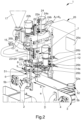
- reference numeral 1 globally indicates a piece of equipment for the production of stuffed cheese, particularly burrata cheese.
- the equipment 1 comprises at least one base frame 2 and supporting means 3 for at least one cheese C of the "pasta filata" type, which are associated with the base frame 2.
- the equipment 1 also comprises:
- the movement means 20, 21 are adapted to mutually move the supporting means 3, the gripping means 6 and the filling means 7 during the different operational phases.
- the gripping means 6, the filling means 7 and the movement means 20, 21 will be described in more detail later in the present disclosure.
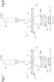
- the supporting means 3 comprise at least a first container element 51 defining a first housing 51a adapted to contain the cheese C and at least a second container element 52 defining a second housing 52a adapted to contain the stuffed cheese S.
- each of the container elements 51, 52 is of the type of a cup and is provided with the relevant housing 51a, 52a and with a relevant stem 5b which helps to space the housing itself apart from the supporting plane 4.
- the housings 51a, 52a have a substantially sphere portion conformation.
- Each of the housings 51a, 52a has a relevant radius of curvature and according to the invention the radius of curvature of the second housing 52a is greater than the radius of curvature of the first housing 51a.
- the equipment 1 allows both the cheese C and the stuffed cheese S to maintain a substantially spherical shape throughout the entire working process.
- the container element 51, 52 can be made of thermally insulating material, so as to maintain the temperature of the cheese C, which needs to be worked at high temperatures.
- the container element 51, 52 may be made of a metal material, characterized by minimal thermal resistance and capable of rapidly reaching the temperature of the cheese C.
- the supporting means 3 conveniently comprise a supporting plane 4 of the container elements 51, 52 which is movable on the base frame 2 along a direction of forward movement D.
- the supporting plane 4 is of the type of a conveyor belt and the direction of forward movement D is substantially linear. It cannot however be ruled out that the supporting plane 4 may be of the type of a rotary carousel with a substantially circular direction of forward movement D. Other embodiments wherein the supporting plane 4 is stationary cannot be ruled out.
- the movement of the supporting plane 4 is of the discrete type and allows the container elements 51, 52 to be positioned between different operational stations.
- the supporting plane 4 is movable along the direction of forward movement D in order to position the container elements 51, 52 between:
- the cheese C is positioned inside the first housing 51a of the first container element 51.
- the gripping means 6 retain the portion P and the filling means 7 of the cheese C are fitted inside the cheese C, through the portion P, to inject the stuffing inside the cheese C to obtain the stuffed cheese S.
- the cheese C is moved away from the first housing 51a in order to allow it to be filled and the resulting expansion of the pasta filata.
- the supporting plane 4 is moved to bring the second container element 52 into the receiving station so as to receive the freshly prepared stuffed cheese S.
- This embodiment allows producing stuffed cheese S in a continuous cycle and without the need for the second container element 52 to unload the stuffed cheese S before starting a new cycle.
- the equipment 1 comprises gripping means 6 adapted to retain the cheese C and, after filling, the stuffed cheese S.
- the gripping means 6 comprise at least one gripping frame 8 associated with the base frame 2 and at least one diaphragm device 9, associated with the gripping frame 8 and closable around the cheese C to retain the portion P and openable to release the stuffed cheese S.
- the diaphragm device 9 defines a passage hole 10 through which the cheese C can pass.
- the closure of the diaphragm device 9 causes a gradual closure of the passage hole 10 until the cheese C is intercepted.
- the diaphragm device 9 comprises a plurality of gripping elements 11 associated with the gripping frame 8, arranged along a circumference.
- the gripping elements 11 are arranged to surround the passage hole 10 and are mutually movable in rotation around their respective axes of rotation R between at least one working position, wherein they are approached to the centre of the circumference to intercept the cheese C and retain the portion P, and at least one home position, wherein they are moved away from the centre to release the cheese C.
- the gripping elements 11 move at the same time in a concentric manner to intercept the portion P and keep the cheese C stationary.
- the diaphragm device 9 is provided with rotational means 12 of the gripping elements 11 between at least the working position and the home position, comprising at least one connecting element 13 associated with the gripping elements 11.
- the connecting element 13 has a substantially circular shape, is arranged on top of the gripping elements 11 and comprises a plurality of slots 13a, arranged along the circumference, each associated with a corresponding pin 11a defined on a respective gripping element 11.
- the pin 11a is accommodated in a sliding manner inside the slot 13a, the shape of which determines the movement trajectory of the pin 11a and thus the amplitude of rotation of the gripping element 11 around the respective axis of rotation R.
- the rotational means 12 comprises at least one actuating body 14 operationally connected to the connecting element 13 by means of a gear wheel 14a adapted to mesh on a respective toothed portion 13b defined on the connecting element itself.
- the rotation of the gear wheel 14a in the two directions of rotation determines the movement of the gripping elements 11 between the working position and the home position.
- the rotation of the connecting element 13 determines the displacement of the slots 13a which in turn drive the respective pins 11a and transfer the movement to the gripping elements 11.
- the gripping elements 11 can be conveniently moved towards a sealing position wherein the passage hole 10 is further closed and wherein the gripping elements 11 apply a pressure force on the portion P in order to firmly close the stuffed cheese S.
- the stuffed cheese S has a sealing area that divides the portion P from the stuffed part below.
- the gripping elements 11 can also be moved further towards a cutting position wherein the passage hole 10 is completely closed; in the cutting position, the gripping elements 11 determine the detachment of the portion P from the stuffed cheese S.
- the equipment 1 allows, in actual facts, the production of stuffed cheese S provided with the characteristic "bag” shape and/or stuffed cheese S having a spheroidal shape, wherein the portion P is removed from the stuffed cheese S.
- the portion P remains on the diaphragm device 9 until the next movement of the gripping elements 11 towards the home position, wherein it is deposited on the supporting plane 4 by gravity.
- the equipment 1 may comprise a plurality of diaphragm devices 9, arranged in a concentric manner and independently operable depending on the type of stuffed cheese S to be obtained.
- two identical diaphragm devices 9 arranged on top of each other may be used; in the case of the production of a small stuffed cheese S, only one diaphragm device 9 is operated in order to retain a reduced portion P; whereas, for the production of a larger stuffed cheese S, it will be necessary to retain a larger portion P and both the diaphragm devices 9 will be operated at the same time.
- one of the diaphragm devices 9 may comprise gripping elements 11 provided with a sharp portion adapted to easily remove the portion P after filling the cheese C; in such a case, the equipment 1 comprises at least one diaphragm device 9 adapted to seal the portion P and at least one diaphragm device 9 adapted to remove it.
- the gripping means 6 may comprise a gripper device associated with the gripping frame 8 and movable to retain and/or seal the cheese C and/or to remove the portion P from the stuffed cheese S.
- the equipment 1 comprises filling means 7 adapted to inject the stuffing into the cheese C.
- the filling means 7 comprise at least one filling frame 15 associated with the base frame 2 and at least one injector device 16 associated with the filling frame 15 and adapted to inject the stuffing into the cheese C.
- the injector device 16 is partly inserted into the cheese C through the portion P, suitably retained by the gripping means 6, and delivers the stuffing, contained in the tank 17, into the cheese C.
- the injector device 16 is pulled out of the portion P to obtain the stuffed cheese S and the gripping means 6 seal and possibly remove the portion P.
- the stuffed cheese S obtained this way is released from the gripping means 6 and transferred towards the unloading position; in particular, the gripping elements 11 are moved towards the home position to free the passage hole 10.
- any removed portion P is released on the supporting plane 4 to allow it to be moved away, together with the stuffed cheese S, from the stuffing station towards the unloading station.
- the equipment 1 comprises at least one cooling tub 19a, 19b, located at the unloading station, inside which the stuffed cheese S is transferred.
- the supporting plane 4 causes the container elements 51, 52 to overturn, thus causing the stuffed cheese S to fall from the second container element 52 into the cooling tub 19a, 19b.
- the cooling tub 19a, 19b comprises a first tub 19a adapted to contain the portions P and a second tub 19b adapted to contain the stuffed cheese S.
- first tub 19a and the second tub 19b are aligned along the direction of forward movement D so that the first tub 19a is placed in the immediate vicinity of the supporting plane 4.
- the special solution of providing container elements 51, 52 provided with the stem 5b allows, as a result of the movement of the supporting plane 4 at the unloading station, the portion P to fall into the first tub 19a and the stuffed cheese S to fall into the second tub 19b.
- the equipment 1 comprises an individual cooling tub and that the separation of the stuffed cheese S and the portions P is carried out at a later date.
- the equipment 1 comprises movement means 20, 21 adapted to move at least one of either the supporting means 3, the gripping means 6 or the filling means 7.
- the movement means 20, 21 comprise at least one mutual movement unit 20 between the supporting means 3 and the gripping means 6, and at least one mutual movement assembly 21 between the gripping means 6 and the filling means 7.
- the mutual movement unit 20 is adapted to move at least one of either the supporting means 3 or the gripping means 6 with respect to the other along an axis of travel A1 substantially perpendicular to the supporting plane 4.
- the mutual movement unit 20 has the function of approaching or moving away the supporting means 3 to/from the gripping means 6 in order to allow retaining the cheese C by the diaphragm device 9.
- the mutual movement unit 20 is adapted to move the gripping means 6 with respect to the supporting means 3.
- the mutual movement unit 20 also has the function of moving the diaphragm device 9 away from the first container element 51, by lifting the cheese C from the first housing 51a during filling by the filling means 7 and bringing it closer to the second container element 52 to rest the stuffed cheese S in the second housing 52a, at the end of the filling operation.
- the mutual movement unit 20 comprises a driving unit 22 operationally connected to the gripping frame 8 and a guidance unit 23 associated with the base frame 2 and extending along the axis of travel A1.
- the gripping frame 8 is associated with the guidance unit 23 in a sliding manner.
- the driving unit 22 comprises a rack-and-pinion element 22a, associated with the gripping frame 8, substantially parallel to the guidance unit 23, and an actuating device 22b, of the type of an electric motor, connected to the rack-and-pinion element itself and adapted to move the gripping frame 8 on the guidance unit 23.
- the mutual movement assembly 21 is adapted to move at least one of either the gripping means 6 or the filling means 7 with respect to the other along an axis of sliding A2 substantially perpendicular to the supporting plane 4.
- the mutual movement assembly 21 has the function of bringing the filling means 7 and the gripping means 6 close to or further away from each other to allow the injector device 16 to be inserted into and removed from the portion P.
- the mutual movement assembly 21 is adapted to move the filling means 7 with respect to the gripping means 6.
- the mutual movement assembly 21 also has the function of moving the injector device 16 with respect to the first container element 5 during filling, substantially at the same time as the gripping means 6, in order to facilitate the deformation of the cheese C.
- the mutual movement assembly 21 comprises a motor assembly 24 operationally connected to the filling frame 15 and a guidance assembly 25 associated with the base frame 2 and extending along the axis of sliding A2.
- the filling frame 15 is associated with the guidance assembly 25 in a sliding manner.
- the motor assembly 24 comprises at least one rack-and-pinion body 24a, associated with the filling frame 15, which is substantially parallel to the guidance assembly 25, and an actuating element 24b, of the type of an electric motor, connected to the rack-and-pinion body itself and adapted to move the filling frame 15 on the guidance assembly 25.
- the guidance assembly 25 coincides with the guidance unit 23 and the axis of sliding A2 coincides with the axis of travel A1.
- the filling frame 15 and the gripping frame 8 are arranged one on top of the other, mounted on the same rails and movable along the same axis as the supporting means 3.
- the equipment 1 also comprises an electronic control system 26 provided with at least one electronic unit 26a configured to operate at least one of either the supporting means 3, the gripping means 6, the filling means 7, the mutual movement unit 20 or the mutual movement assembly 21.
- the electronic control system 26 also comprises at least one position sensor 26b operationally connected to the electronic unit 26a and configured to determine at least one position of at least one of either the connecting element 13, the gripping frame 8 or the filling frame 15.
- the operation of the equipment 1 according to the invention is as follows.
- the first container element 51 is positioned in the loading station where the cheese C is arranged into the first housing 51a.
- the first container element 51 is then transferred by means of the supporting plane 4, along the direction of forward movement D, towards the filling station. At this point, the mutual movement unit 20 moves the gripping means 6 towards the supporting means 3.
- the driving unit 22 brings the diaphragm device 9 closer to the cheese C so that the latter can transit through the passage hole 10.
- the actuating body 14 of the rotational means 12 is operated by determining the rotation of the gripping elements 11 towards the working position, partly closing the passage hole 10 and retaining the portion P.
- the mutual movement unit 20 moves the gripping means 6 so as to lift the cheese C from the first container element 51.
- the mutual movement assembly 21 moves the filling means 7 towards the gripping means 6.
- the motor assembly 24 brings the injector device 16 closer to the diaphragm device 9 so as to allow the injector device itself to be inserted into the cheese C through the portion P.
- the pumping device 18 is operated to allow the stuffing to be delivered.
- the mutual movement unit 20 and the mutual movement assembly 21 move the gripping means 6 and the filling means 7 away at the same time from the supporting means 3, respectively, in order to facilitate the deformation of the cheese C.
- the supporting plane 4 moves forward along the direction of forward movement D so as to bring the second container element 52 to the receiving station.
- the mutual movement assembly 21 moves the filling means 7 away from the gripping means 6 to allow the injector device 16 to be pulled out of the portion P.
- the mutual movement unit 20 brings the gripping means 6 closer to the supporting means 3 to rest the stuffed cheese S into the second housing 52a.
- the gripping means 6 are adapted to completely lift the cheese C from the first container element 51, prior to filling, so as to allow an effective increase in volume of the stuffed cheese S and then to rest the latter in the second container element 52 at the end of filling.
- the gripping means 6 are adapted to lift the cheese C only partly, so that during filling the weight of the stuffed cheese S is discharged onto the first container element 51. In this case, the gripping means 6 ensure that the stuffed cheese S is fully lifted only at the end of filling, and only then the supporting plane 4 moves forward so as to bring the second container element 52 to the receiving station.
- the gripping elements 11 are moved towards the sealing position to apply pressure on the portion P and close the stuffed cheese S.
- the gripping elements 11 are further rotated towards the cutting position to remove the portion P from the stuffed cheese S.
- the gripping elements 11 are brought to the home position to release the stuffed cheese S, and, if necessary, the removed portion P, onto the supporting means 3.
- the supporting plane 4 displaces the second container element 52 containing the stuffed cheese S and, if necessary, the removed portion P, towards the unloading station where they are transferred to the respective tubs 19a and 19b.
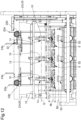
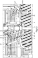
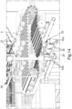
- the gripping means 6 comprise a plurality of diaphragm devices 9 associated with the gripping frame 8 and arranged side by side along at least one working direction W transverse to the direction of forward movement D.
- the working direction W is substantially orthogonal to the direction of forward movement D.
- Each of the diaphragm devices 9 is adapted to retain a respective cheese C.
- the supporting means 3 comprise a plurality of rows of container elements F, wherein the first container elements 51 are arranged side by side along relevant first positioning directions B1 substantially parallel to the working direction W and the second container elements 52 are arranged side by side along relevant second positioning directions B2 substantially parallel to the first positioning directions B1.
- the number of the rows of container elements F corresponds to the number of diaphragm devices 9.
- the rows of container elements F are arranged substantially parallel to each other and parallel to the direction of forward movement D.
- the positioning directions B1, B2 are substantially orthogonal to the direction of forward movement D.
- the container elements 51, 52 are therefore arranged so that when the first container element 51 of one of the rows of container elements F is in the loading station, the other rows of container elements F also have a first container element 51 in the same station.
- the equipment 1 according to the second embodiment allows, therefore, simultaneously working a plurality of cheeses C.
- each diaphragm device 9 comprises a respective actuating body 14.
- the diaphragm devices 9 can, therefore, be operated independently of each other to retain/release the cheese C.
- each diaphragm device 9 corresponds to an injector device 16.
- Each of the injector devices 16 is adapted to inject the stuffing into a respective cheese C.
- the injector devices 16 can therefore be operated independently of each other to deliver the stuffing.
- the equipment 1 according to the second embodiment allows, therefore, both the processing of several cheeses C at the same time and the production of stuffed cheese S of different types.
- the solution of providing the diaphragm devices 9 associated with an individual gripping frame 8 and the injector devices 16 associated with an individual filling frame 15 allows them to be moved simultaneously by means of the driving unit 22 and the motor assembly 24, respectively.
- This solution allows reducing the number of components and movable parts, making the equipment 1 extremely compact and provided with an agile operation.
- the presence sensor 27 is of the type, e.g., of a diffuse reflection photocell.
- the injector device 16 is interlocked to the presence sensor 27 to deliver the stuffing only in the presence of the cheese C in the first container element 51.
- the equipment 1 comprises a presence sensor 27 for each injector device 16.
- the presence sensors 27 are operationally connected to the electronic unit 26a.
- the electronic unit 26a is programmed to operate the pumping device 18 of the corresponding injector device 16.
- the pumping device 18 of the corresponding injector device 16 is not operated so as not to deliver the stuffing.
- the presence sensor 27 can also be applied to the equipment 1 in accordance with the first embodiment shown in Figures 1 to 8 .
- the equipment 1 comprises cleaning means 28 associated with the base frame 2 and adapted to deliver at least one cleaning fluid to at least the gripping means 6.
- the cleaning fluid is of the type, e.g., of hot water and/or a sanitizing product.
- the cleaning means 28 comprise at least one delivering element 29 configured to direct a jet of cleaning fluid towards the diaphragm device 9.
- the delivering element 29 has the function of removing any residual cheese C and/or stuffing that remains on the diaphragm device 9 as a result of the preparation of the stuffed cheese S.
- the cleaning means 28 comprise at least one delivering element 29 for each diaphragm device 9.
- the cleaning means 28 also comprise a dispensing element 30 configured to direct the jet of cleaning fluid towards the container elements 51, 52.
- the dispensing element 30 delivers the cleaning fluid towards the housings 51a, 52a.
- the dispensing element 30 has the function of cleaning the housings 51a, 52a after unloading the stuffed cheese S and before positioning a new cheese C.
- the movement of the supporting plane 4 allows positioning the container elements 51, 52 in a cleaning station wherein they are cleaned before starting a new processing cycle.
- the dispensing element 30 is associated with the base frame 2 below the supporting plane 4.
- the container elements 51, 52 are arranged with their relevant housings 51a, 52a facing downwards and the dispensing element 30 delivers the cleaning fluid upwards.
- the operation therefore, does not require for an additional phase of emptying the container elements 51, 52 from the cleaning fluid to start a new processing cycle.
- the cleaning means 28 comprise a dispensing element 30 for each row of container elements 5.
- the cleaning means 28 therefore, allow the cleaning of the diaphragm devices 9 and of the container elements 51, 52 at each processing cycle.
- the cleaning means 28 may also be applied to the equipment 1 according to the first embodiment shown in Figures 1 to 8 .
- the equipment 1 For the collection and recovery of the cleaning fluid delivered by the cleaning means 28, the equipment 1 comprises a collection tank 32 located below the supporting plane 4, conveniently below the cleaning station.
- any stuffing that has not been correctly injected into the cheeses C by the injector devices 16 is also collected in the collection tank 32.
- All products collected in the collection tank 32 can be drained therefrom (e.g. by suction through a union 33) to be possibly recovered and/or to be definitively discarded.
- the separation of the stuffed cheese S and of the portions P is carried out using an alternative method to that described above.
- the second tub 19b intended to contain the stuffed cheese S is arranged along the direction of forward movement D at the supporting plane 4 and receives the stuffed cheese S when the supporting plane itself moves forward.
- the first tub 19a intended to contain the portions P, on the other hand, is placed laterally to the supporting plane 4, at the base of the equipment 1.
- a slide 31 placed below the supporting plane 4, the portions P are conveyed by gravity (and possibly pushed by means of a jet of water) from the supporting plane 4 to the first tub 19a as the supporting plane 4 moves forward.
- a nozzle can be conveniently provided which is adapted to deliver a jet of water along the slide 31.
- the equipment 1 comprises an additional conveyor belt positioned below the supporting plane 4, adapted to receive the portions P following their fall from the supporting plane 4 and to carry them towards the first tub 19a.
- the equipment according to the invention allows the production of stuffed cheese, particularly burrata cheese, in a totally automated manner in order to avoid the use of skilled labor.
Landscapes
- Life Sciences & Earth Sciences (AREA)
- Animal Husbandry (AREA)
- Environmental Sciences (AREA)
- Chemical & Material Sciences (AREA)
- Engineering & Computer Science (AREA)
- Food Science & Technology (AREA)
- Polymers & Plastics (AREA)
- Dairy Products (AREA)
Claims (10)
- Vorrichtung (1) zur Herstellung von gefülltem Käse, insbesondere von Burrata-Käse, bestehend aus:- mindestens einen Grundrahmen (2);- Stützmittel (3) für mindestens einen Käse (C) des frischen "Pasta-Filata" [alternativ: Spinn- oder Ziehkäse]-Typs, die mit dem Grundrahmen (2) verbunden sind;- Greifmittel (6) für den Käse (C), die mit dem Grundrahmen (2) verbunden und ausgebildet sind, mindestens einen Teil (P) des Käses (C) festzuhalten;- Füllmittel (7) für den Käse (C), die mit dem Grundrahmen (2) verbunden und ausgebildet sind, durch den Teil (P) eine Füllung in den Käse (C) zu spritzen, um einen gefüllten Käse (S) zu erhalten;- mindestens eine Einheit (20) für eine gegenseitige Bewegung zwischen den Stützmitteln (3) und den Greifmitteln (6); und- mindestens eine Anordnung (21) für eine gegenseitige Bewegung zwischen den Greifmitteln (6) und den Füllmitteln (7);dadurch gekennzeichnet, dass
die Stützmittel (3) mindestens ein erstes Behälterelement (51), das ein erstes Gehäuse (51a) definiert, das ausgebildet ist, den Käse (C) aufzunehmen, und mindestens ein zweites Behälterelement (52) umfassen, das ein zweites Gehäuse (52a) definiert, das ausgebildet ist, den gefüllten Käse (S) aufzunehmen, wobei die Gehäuse (51a, 52a) einen relativen Krümmungsradius aufweisen, wobei der Krümmungsradius des zweiten Gehäuses (52a) größer ist als der Krümmungsradius des ersten Gehäuses (51a). - Vorrichtung (1) gemäß Anspruch 1, dadurch gekennzeichnet, dass die Stützmittel (3) eine Stützebene (4) für die Behälterelemente (51, 52) umfassen, die auf dem Grundrahmen (2) entlang einer Vorwärtsbewegungsrichtung (D) beweglich ist.
- Vorrichtung (1) gemäß Anspruch 2, dadurch gekennzeichnet, dass die Stützebene (4) entlang der Vorwärtsbewegungsrichtung (D) beweglich ist, um die Behälterelemente (51, 52) zwischen- einer Beladungsstation, an der das erste Behälterelement (51) den Käse (C) aufnimmt,- einer Füllstation, an der das erste Behälterelement (51) an dem Punkt angeordnet ist, an dem sich die Greifmittel (6) befinden und die Greifmittel (6) den Teil (P) festhalten- einer Aufnahmestation, an der das zweite Behälterelement (52) an dem Punkt angeordnet ist, an dem sich die Greifmittel (6) befinden und die Greifmittel (6) den gefüllten Käse (S) in das zweite Behälterelement (52) freigeben; und- eine Entladestation, an der das zweite Behälterelement (52) den gefüllten Käse (S) freigibt.
- Vorrichtung (1) gemäß Anspruch 2, dadurch gekennzeichnet, dass die Stützmittel (3) mindestens eine Reihe von Behälterelementen (F) umfassen, die eine Vielzahl der ersten Behälterelemente (51) und eine Vielzahl der zweiten Behälterelemente (52) umfassen, die mit der Stützebene (4) verbunden sind und in einer abwechselnden Reihenfolge entlang der Vorwärtsbewegungsrichtung (D) angeordnet sind.
- Vorrichtung (1) gemäß einem oder mehreren der vorhergehenden Ansprüche, dadurch gekennzeichnet, dass die Greifmittel (6) mindestens einen Greifrahmen (8), der mit dem Grundrahmen (2) verbunden ist, und mindestens eine Membranvorrichtung (9) umfasst, die mit dem Greifrahmen (8) verbunden ist und um den Käse (C) herum geschlossen werden kann, um den Teil (P) festzuhalten, und geöffnet werden kann, um den gefüllten Käse (S) freizugeben.
- Vorrichtung (1) gemäß Anspruch 5, dadurch gekennzeichnet, dass die Membranvorrichtung (9) umfasst:- eine Vielzahl von Greifelementen (11), die mit dem Greifrahmen (8) verbunden sind, entlang eines Umfangs angeordnet sind und in Bezug dazu um entsprechende Drehachsen (R) zwischen mindestens einer Arbeitsposition, in der sie dem Zentrum des Umfangs angenähert sind, um den Käse (C) zu erfassen und den Teil (P) festzuhalten, und einer Ausgangsposition beweglich sind, in der sie von dem Zentrum wegbewegt sind, um den gefüllten Käse (S) freizugeben; und- Drehmittel (12) zum Drehen der Greifelemente (11) zwischen der mindestens einen Arbeitsposition und der Ausgangsposition, die mindestens ein Verbindungselement (13), das mit den Greifelementen (11) verbunden ist, und mindestens einem Betätigungskörper (14) umfassen, der mit dem Verbindungselement (13) über ein Zahnrad (14a) wirkverbunden ist, das ausgebildet ist, in einen entsprechenden gezahnten Abschnitt (13b) einzugreifen, der auf dem Verbindungselement (13) ausgebildet ist, wobei die Drehung des Zahnrads (14a) in den beiden Drehrichtungen somit die Bewegung der Greifelemente (11) zwischen der Arbeitsposition und der Ausgangsposition bewirkt.
- Vorrichtung (1) gemäß Anspruch 6, dadurch gekennzeichnet, dass die Greifmittel (6) eine Vielzahl von Membranvorrichtungen (9) umfassen, die mit dem Greifrahmen (8) verbunden sind und entlang mindestens einer Arbeitsrichtung (W) quer zu der Vorwärtsbewegungsrichtung (D) nebeneinander angeordnet sind, wobei jede ausgebildet ist, einen entsprechenden Käse (C) festzuhalten.
- Vorrichtung (1) gemäß Anspruch 7, dadurch gekennzeichnet, dass die Stützmittel (3) eine Vielzahl der Reihen von Behälterelementen (F) umfassen, wobei die ersten Behälterelemente (51) nebeneinander entlang relevanter erster Positionierungsrichtungen (B1) im Wesentlichen parallel zu der Arbeitsrichtung (W) angeordnet sind und die zweiten Behälterelemente (52) nebeneinander entlang relevanter zweiter Positionierungsrichtungen (B2) im Wesentlichen parallel zu den ersten Positionierungsrichtungen (B1) angeordnet sind, wobei die Anzahl der Reihen von Behälterelementen (F) der Anzahl der Membranvorrichtungen (9) entspricht.
- Vorrichtung (1) gemäß einem oder mehreren der vorhergehenden Ansprüche, dadurch gekennzeichnet, dass die Füllmittel (7) umfassen:- mindestens einen Füllrahmen (15), der mit dem Grundrahmen (2) verbunden ist;- mindestens eine Einspritzvorrichtung (16), die mit dem Füllrahmen (15) verbunden und ausgebildet ist, die Füllung in den Käse (C) einzuspritzen; und- mindestens einen Tank (17), der ausgebildet ist, die Füllung aufzunehmen, der in einer fluidbetriebenen Weise mit der Einspritzvorrichtung (16) verbunden ist.
- Vorrichtung (1) nach Anspruch 9, dadurch gekennzeichnet, dass die Füllmittel (7) eine Vielzahl von Einspritzvorrichtungen (16) umfassen, die in fluidbetriebener Weise mit dem Tank (17) verbunden sind, mit dem Füllrahmen (15) verbunden sind und entlang mindestens einer Betriebsrichtung (G) quer zu der Vorwärtsbewegungsrichtung (D) nebeneinander angeordnet sind, wobei jede ausgebildet ist, die Füllung in einen entsprechenden Käse (C) einzuspritzen.
Applications Claiming Priority (2)
| Application Number | Priority Date | Filing Date | Title |
|---|---|---|---|
| IT102021000011762A IT202100011762A1 (it) | 2021-05-07 | 2021-05-07 | Apparecchiatura per la produzione di formaggi ripieni, particolarmente burrate |
| PCT/IB2022/054024 WO2022234423A1 (en) | 2021-05-07 | 2022-05-02 | Equipment for the production of stuffed cheese, particularly burrata cheese |
Publications (2)
| Publication Number | Publication Date |
|---|---|
| EP4333609A1 EP4333609A1 (de) | 2024-03-13 |
| EP4333609B1 true EP4333609B1 (de) | 2025-06-25 |
Family
ID=76921267
Family Applications (1)
| Application Number | Title | Priority Date | Filing Date |
|---|---|---|---|
| EP22722355.9A Active EP4333609B1 (de) | 2021-05-07 | 2022-05-02 | Vorrichtung zur herstellung von gefülltem käse, insbesondere brata-käse |
Country Status (8)
| Country | Link |
|---|---|
| US (1) | US20240224927A1 (de) |
| EP (1) | EP4333609B1 (de) |
| JP (1) | JP2024517005A (de) |
| AU (1) | AU2022268709A1 (de) |
| CA (1) | CA3218055A1 (de) |
| ES (1) | ES3042419T3 (de) |
| IT (1) | IT202100011762A1 (de) |
| WO (1) | WO2022234423A1 (de) |
Families Citing this family (3)
| Publication number | Priority date | Publication date | Assignee | Title |
|---|---|---|---|---|
| IT202200024267A1 (it) * | 2022-11-24 | 2024-05-24 | Latteria Montello S P A | Sistema e procedimento per la produzione di prodotti alimentari contenenti un riempimento |
| IT202300018177A1 (it) | 2023-09-04 | 2025-03-04 | Amc S R L | Sistema sterile di trasferimento automatizzato di burrata e similari da macchine formatrici a macchine confezionatrici, e metodo associato |
| IT202300020217A1 (it) * | 2023-09-29 | 2025-03-29 | Carmine Marotta | Apparecchiatura per la produzione di formaggi ripieni, particolarmente burrate |
Family Cites Families (5)
| Publication number | Priority date | Publication date | Assignee | Title |
|---|---|---|---|---|
| FR2726160B1 (fr) * | 1994-10-26 | 1996-11-29 | Bongrain | Aliment composite et son procede de fabrication |
| US6355288B1 (en) * | 1999-12-30 | 2002-03-12 | Digiacomo Primo | Pasta stuffing machine and method |
| JP3091221U (ja) * | 2002-06-27 | 2003-01-24 | 株式会社クレストジャパン | 鶏卵状チーズ |
| TW200838443A (en) * | 2006-12-27 | 2008-10-01 | Rheon Automatic Machinery Co | Method and apparatus for producing wrapped food |
| IT201800001009A1 (it) * | 2018-01-17 | 2019-07-17 | Vuolo Ciro Di | Macchina automatica e modo di utilizzo per burrate, con apparati integrati di preparazione stracciatella e pasta filata, di riempimento automatico e di raffreddamento del prodotto finito. |
-
2021
- 2021-05-07 IT IT102021000011762A patent/IT202100011762A1/it unknown
-
2022
- 2022-05-02 US US18/559,351 patent/US20240224927A1/en active Pending
- 2022-05-02 ES ES22722355T patent/ES3042419T3/es active Active
- 2022-05-02 JP JP2023568185A patent/JP2024517005A/ja active Pending
- 2022-05-02 EP EP22722355.9A patent/EP4333609B1/de active Active
- 2022-05-02 AU AU2022268709A patent/AU2022268709A1/en not_active Abandoned
- 2022-05-02 CA CA3218055A patent/CA3218055A1/en active Pending
- 2022-05-02 WO PCT/IB2022/054024 patent/WO2022234423A1/en not_active Ceased
Also Published As
| Publication number | Publication date |
|---|---|
| CA3218055A1 (en) | 2022-11-10 |
| IT202100011762A1 (it) | 2022-11-07 |
| JP2024517005A (ja) | 2024-04-18 |
| US20240224927A1 (en) | 2024-07-11 |
| AU2022268709A1 (en) | 2023-12-21 |
| WO2022234423A1 (en) | 2022-11-10 |
| ES3042419T3 (en) | 2025-11-20 |
| EP4333609A1 (de) | 2024-03-13 |
Similar Documents
| Publication | Publication Date | Title |
|---|---|---|
| AU2020382987B2 (en) | Equipment for the production of stuffed cheese, particularly burrata cheese | |
| US20240224927A1 (en) | Equipment for the production of stuffed cheese, particularly burrata cheese | |
| EP4192744B1 (de) | Herstellungsvorrichtung und herstellungsverfahren für kapseln vom infusionstyp | |
| US20250017167A1 (en) | Equipment for the production of stuffed cheese, particularly burrata cheese | |
| WO2017149554A1 (en) | Machine for the automatic oriented positioning of fruits in a primary packing container | |
| US20240147953A1 (en) | Equipment for the production of stuffed cheese, particularly burrata cheese | |
| RU2835984C1 (ru) | Оборудование для производства сыра с начинкой, в частности сыра буррата | |
| RU2858281C2 (ru) | Оборудование для производства сыра с начинкой, в частности сыра буррата | |
| EP4374710A1 (de) | System und verfahren zur herstellung von lebensmittelprodukten mit einer füllung | |
| WO2025068853A1 (en) | Appliance for the production of stuffed cheese, particularly burrata cheese | |
| WO2025078931A1 (en) | A machine for producing stuffed cheese, in particular burrata cheese | |
| IT202300022167A1 (it) | Macchina per la produzione di un formaggio, in particolare del tipo a pasta filata | |
| JP2023535246A (ja) | ペンチ型装置および関連する移送器具 |
Legal Events
| Date | Code | Title | Description |
|---|---|---|---|
| STAA | Information on the status of an ep patent application or granted ep patent |
Free format text: STATUS: UNKNOWN |
|
| STAA | Information on the status of an ep patent application or granted ep patent |
Free format text: STATUS: THE INTERNATIONAL PUBLICATION HAS BEEN MADE |
|
| PUAI | Public reference made under article 153(3) epc to a published international application that has entered the european phase |
Free format text: ORIGINAL CODE: 0009012 |
|
| STAA | Information on the status of an ep patent application or granted ep patent |
Free format text: STATUS: REQUEST FOR EXAMINATION WAS MADE |
|
| 17P | Request for examination filed |
Effective date: 20231205 |
|
| AK | Designated contracting states |
Kind code of ref document: A1 Designated state(s): AL AT BE BG CH CY CZ DE DK EE ES FI FR GB GR HR HU IE IS IT LI LT LU LV MC MK MT NL NO PL PT RO RS SE SI SK SM TR |
|
| DAV | Request for validation of the european patent (deleted) | ||
| DAX | Request for extension of the european patent (deleted) | ||
| REG | Reference to a national code |
Ref country code: DE Free format text: PREVIOUS MAIN CLASS: A01J0025000000 Ref legal event code: R079 Ref document number: 602022016449 Country of ref document: DE Ipc: A23C0019068000 |
|
| GRAP | Despatch of communication of intention to grant a patent |
Free format text: ORIGINAL CODE: EPIDOSNIGR1 |
|
| STAA | Information on the status of an ep patent application or granted ep patent |
Free format text: STATUS: GRANT OF PATENT IS INTENDED |
|
| RIC1 | Information provided on ipc code assigned before grant |
Ipc: A23C 19/09 20060101ALI20241107BHEP Ipc: A01J 27/04 20060101ALI20241107BHEP Ipc: A01J 25/12 20060101ALI20241107BHEP Ipc: A01J 25/00 20060101ALI20241107BHEP Ipc: A23C 19/068 20060101AFI20241107BHEP |
|
| INTG | Intention to grant announced |
Effective date: 20241114 |
|
| GRAJ | Information related to disapproval of communication of intention to grant by the applicant or resumption of examination proceedings by the epo deleted |
Free format text: ORIGINAL CODE: EPIDOSDIGR1 |
|
| STAA | Information on the status of an ep patent application or granted ep patent |
Free format text: STATUS: REQUEST FOR EXAMINATION WAS MADE |
|
| GRAP | Despatch of communication of intention to grant a patent |
Free format text: ORIGINAL CODE: EPIDOSNIGR1 |
|
| STAA | Information on the status of an ep patent application or granted ep patent |
Free format text: STATUS: GRANT OF PATENT IS INTENDED |
|
| GRAS | Grant fee paid |
Free format text: ORIGINAL CODE: EPIDOSNIGR3 |
|
| INTC | Intention to grant announced (deleted) | ||
| INTG | Intention to grant announced |
Effective date: 20250325 |
|
| GRAA | (expected) grant |
Free format text: ORIGINAL CODE: 0009210 |
|
| STAA | Information on the status of an ep patent application or granted ep patent |
Free format text: STATUS: THE PATENT HAS BEEN GRANTED |
|
| AK | Designated contracting states |
Kind code of ref document: B1 Designated state(s): AL AT BE BG CH CY CZ DE DK EE ES FI FR GB GR HR HU IE IS IT LI LT LU LV MC MK MT NL NO PL PT RO RS SE SI SK SM TR |
|
| REG | Reference to a national code |
Ref country code: GB Ref legal event code: FG4D |
|
| REG | Reference to a national code |
Ref country code: CH Ref legal event code: EP |
|
| REG | Reference to a national code |
Ref country code: CH Ref legal event code: EP |
|
| REG | Reference to a national code |
Ref country code: IE Ref legal event code: FG4D |
|
| REG | Reference to a national code |
Ref country code: DE Ref legal event code: R096 Ref document number: 602022016449 Country of ref document: DE |
|
| REG | Reference to a national code |
Ref country code: DE Ref legal event code: R081 Ref document number: 602022016449 Country of ref document: DE Owner name: MAROTTA EVOLUTION S.R.L., IT Free format text: FORMER OWNER: MAROTTA EVOLUTION S.R.L., CASALECCHIO DI RENO, BOLOGNA, IT |
|
| RAP4 | Party data changed (patent owner data changed or rights of a patent transferred) |
Owner name: MAROTTA EVOLUTION S.R.L. |
|
| P01 | Opt-out of the competence of the unified patent court (upc) registered |
Free format text: CASE NUMBER: UPC_APP_5470_4333609/2025 Effective date: 20250901 |
|
| PG25 | Lapsed in a contracting state [announced via postgrant information from national office to epo] |
Ref country code: FI Free format text: LAPSE BECAUSE OF FAILURE TO SUBMIT A TRANSLATION OF THE DESCRIPTION OR TO PAY THE FEE WITHIN THE PRESCRIBED TIME-LIMIT Effective date: 20250625 |
|
| REG | Reference to a national code |
Ref country code: LT Ref legal event code: MG9D |
|
| PG25 | Lapsed in a contracting state [announced via postgrant information from national office to epo] |
Ref country code: NO Free format text: LAPSE BECAUSE OF FAILURE TO SUBMIT A TRANSLATION OF THE DESCRIPTION OR TO PAY THE FEE WITHIN THE PRESCRIBED TIME-LIMIT Effective date: 20250925 Ref country code: GR Free format text: LAPSE BECAUSE OF FAILURE TO SUBMIT A TRANSLATION OF THE DESCRIPTION OR TO PAY THE FEE WITHIN THE PRESCRIBED TIME-LIMIT Effective date: 20250926 |
|
| PG25 | Lapsed in a contracting state [announced via postgrant information from national office to epo] |
Ref country code: BG Free format text: LAPSE BECAUSE OF FAILURE TO SUBMIT A TRANSLATION OF THE DESCRIPTION OR TO PAY THE FEE WITHIN THE PRESCRIBED TIME-LIMIT Effective date: 20250625 |
|
| PG25 | Lapsed in a contracting state [announced via postgrant information from national office to epo] |
Ref country code: HR Free format text: LAPSE BECAUSE OF FAILURE TO SUBMIT A TRANSLATION OF THE DESCRIPTION OR TO PAY THE FEE WITHIN THE PRESCRIBED TIME-LIMIT Effective date: 20250625 |
|
| PG25 | Lapsed in a contracting state [announced via postgrant information from national office to epo] |
Ref country code: RS Free format text: LAPSE BECAUSE OF FAILURE TO SUBMIT A TRANSLATION OF THE DESCRIPTION OR TO PAY THE FEE WITHIN THE PRESCRIBED TIME-LIMIT Effective date: 20250925 |
|
| PG25 | Lapsed in a contracting state [announced via postgrant information from national office to epo] |
Ref country code: LV Free format text: LAPSE BECAUSE OF FAILURE TO SUBMIT A TRANSLATION OF THE DESCRIPTION OR TO PAY THE FEE WITHIN THE PRESCRIBED TIME-LIMIT Effective date: 20250625 |
|
| REG | Reference to a national code |
Ref country code: NL Ref legal event code: MP Effective date: 20250625 |
|
| PG25 | Lapsed in a contracting state [announced via postgrant information from national office to epo] |
Ref country code: NL Free format text: LAPSE BECAUSE OF FAILURE TO SUBMIT A TRANSLATION OF THE DESCRIPTION OR TO PAY THE FEE WITHIN THE PRESCRIBED TIME-LIMIT Effective date: 20250625 |
|
| REG | Reference to a national code |
Ref country code: ES Ref legal event code: FG2A Ref document number: 3042419 Country of ref document: ES Kind code of ref document: T3 Effective date: 20251120 |
|
| PG25 | Lapsed in a contracting state [announced via postgrant information from national office to epo] |
Ref country code: PT Free format text: LAPSE BECAUSE OF FAILURE TO SUBMIT A TRANSLATION OF THE DESCRIPTION OR TO PAY THE FEE WITHIN THE PRESCRIBED TIME-LIMIT Effective date: 20251027 |
|
| REG | Reference to a national code |
Ref country code: AT Ref legal event code: MK05 Ref document number: 1805475 Country of ref document: AT Kind code of ref document: T Effective date: 20250625 |
|
| PG25 | Lapsed in a contracting state [announced via postgrant information from national office to epo] |
Ref country code: IS Free format text: LAPSE BECAUSE OF FAILURE TO SUBMIT A TRANSLATION OF THE DESCRIPTION OR TO PAY THE FEE WITHIN THE PRESCRIBED TIME-LIMIT Effective date: 20251025 |
|
| PG25 | Lapsed in a contracting state [announced via postgrant information from national office to epo] |
Ref country code: AT Free format text: LAPSE BECAUSE OF FAILURE TO SUBMIT A TRANSLATION OF THE DESCRIPTION OR TO PAY THE FEE WITHIN THE PRESCRIBED TIME-LIMIT Effective date: 20250625 Ref country code: SM Free format text: LAPSE BECAUSE OF FAILURE TO SUBMIT A TRANSLATION OF THE DESCRIPTION OR TO PAY THE FEE WITHIN THE PRESCRIBED TIME-LIMIT Effective date: 20250625 |
|
| PG25 | Lapsed in a contracting state [announced via postgrant information from national office to epo] |
Ref country code: CZ Free format text: LAPSE BECAUSE OF FAILURE TO SUBMIT A TRANSLATION OF THE DESCRIPTION OR TO PAY THE FEE WITHIN THE PRESCRIBED TIME-LIMIT Effective date: 20250625 |
|
| PG25 | Lapsed in a contracting state [announced via postgrant information from national office to epo] |
Ref country code: PL Free format text: LAPSE BECAUSE OF FAILURE TO SUBMIT A TRANSLATION OF THE DESCRIPTION OR TO PAY THE FEE WITHIN THE PRESCRIBED TIME-LIMIT Effective date: 20250625 |
|
| PG25 | Lapsed in a contracting state [announced via postgrant information from national office to epo] |
Ref country code: EE Free format text: LAPSE BECAUSE OF FAILURE TO SUBMIT A TRANSLATION OF THE DESCRIPTION OR TO PAY THE FEE WITHIN THE PRESCRIBED TIME-LIMIT Effective date: 20250625 |
|
| PG25 | Lapsed in a contracting state [announced via postgrant information from national office to epo] |
Ref country code: SK Free format text: LAPSE BECAUSE OF FAILURE TO SUBMIT A TRANSLATION OF THE DESCRIPTION OR TO PAY THE FEE WITHIN THE PRESCRIBED TIME-LIMIT Effective date: 20250625 |
|
| REG | Reference to a national code |
Ref country code: DE Ref legal event code: R097 Ref document number: 602022016449 Country of ref document: DE |
|
| PG25 | Lapsed in a contracting state [announced via postgrant information from national office to epo] |
Ref country code: DK Free format text: LAPSE BECAUSE OF FAILURE TO SUBMIT A TRANSLATION OF THE DESCRIPTION OR TO PAY THE FEE WITHIN THE PRESCRIBED TIME-LIMIT Effective date: 20250625 |
|
| PLBE | No opposition filed within time limit |
Free format text: ORIGINAL CODE: 0009261 |
|
| STAA | Information on the status of an ep patent application or granted ep patent |
Free format text: STATUS: NO OPPOSITION FILED WITHIN TIME LIMIT |
|
| REG | Reference to a national code |
Ref country code: CH Ref legal event code: L10 Free format text: ST27 STATUS EVENT CODE: U-0-0-L10-L00 (AS PROVIDED BY THE NATIONAL OFFICE) Effective date: 20260507 |