EP4333389A1 - Kommunikationsvorrichtung und kommunikationsverfahren - Google Patents
Kommunikationsvorrichtung und kommunikationsverfahren Download PDFInfo
- Publication number
- EP4333389A1 EP4333389A1 EP22795263.7A EP22795263A EP4333389A1 EP 4333389 A1 EP4333389 A1 EP 4333389A1 EP 22795263 A EP22795263 A EP 22795263A EP 4333389 A1 EP4333389 A1 EP 4333389A1
- Authority
- EP
- European Patent Office
- Prior art keywords
- signal
- transmission
- station
- communication
- communication apparatus
- Prior art date
- Legal status (The legal status is an assumption and is not a legal conclusion. Google has not performed a legal analysis and makes no representation as to the accuracy of the status listed.)
- Pending
Links
Images









Classifications
-
- H—ELECTRICITY
- H04—ELECTRIC COMMUNICATION TECHNIQUE
- H04L—TRANSMISSION OF DIGITAL INFORMATION, e.g. TELEGRAPHIC COMMUNICATION
- H04L27/00—Modulated-carrier systems
- H04L27/26—Systems using multi-frequency codes
- H04L27/2601—Multicarrier modulation systems
- H04L27/2602—Signal structure
- H04L27/2605—Symbol extensions, e.g. Zero Tail, Unique Word [UW]
-
- H—ELECTRICITY
- H04—ELECTRIC COMMUNICATION TECHNIQUE
- H04L—TRANSMISSION OF DIGITAL INFORMATION, e.g. TELEGRAPHIC COMMUNICATION
- H04L27/00—Modulated-carrier systems
- H04L27/26—Systems using multi-frequency codes
- H04L27/2601—Multicarrier modulation systems
- H04L27/2602—Signal structure
- H04L27/2605—Symbol extensions, e.g. Zero Tail, Unique Word [UW]
- H04L27/2607—Cyclic extensions
-
- H—ELECTRICITY
- H04—ELECTRIC COMMUNICATION TECHNIQUE
- H04L—TRANSMISSION OF DIGITAL INFORMATION, e.g. TELEGRAPHIC COMMUNICATION
- H04L1/00—Arrangements for detecting or preventing errors in the information received
- H04L1/08—Arrangements for detecting or preventing errors in the information received by repeating transmission, e.g. Verdan system
-
- H—ELECTRICITY
- H04—ELECTRIC COMMUNICATION TECHNIQUE
- H04L—TRANSMISSION OF DIGITAL INFORMATION, e.g. TELEGRAPHIC COMMUNICATION
- H04L27/00—Modulated-carrier systems
- H04L27/26—Systems using multi-frequency codes
- H04L27/2601—Multicarrier modulation systems
- H04L27/2602—Signal structure
-
- H—ELECTRICITY
- H04—ELECTRIC COMMUNICATION TECHNIQUE
- H04L—TRANSMISSION OF DIGITAL INFORMATION, e.g. TELEGRAPHIC COMMUNICATION
- H04L27/00—Modulated-carrier systems
- H04L27/26—Systems using multi-frequency codes
- H04L27/2601—Multicarrier modulation systems
- H04L27/2602—Signal structure
- H04L27/261—Details of reference signals
- H04L27/2613—Structure of the reference signals
- H04L27/26132—Structure of the reference signals using repetition
-
- H—ELECTRICITY
- H04—ELECTRIC COMMUNICATION TECHNIQUE
- H04L—TRANSMISSION OF DIGITAL INFORMATION, e.g. TELEGRAPHIC COMMUNICATION
- H04L1/00—Arrangements for detecting or preventing errors in the information received
- H04L1/0078—Avoidance of errors by organising the transmitted data in a format specifically designed to deal with errors, e.g. location
- H04L1/0079—Formats for control data
- H04L1/008—Formats for control data where the control data relates to payload of a different packet
-
- Y—GENERAL TAGGING OF NEW TECHNOLOGICAL DEVELOPMENTS; GENERAL TAGGING OF CROSS-SECTIONAL TECHNOLOGIES SPANNING OVER SEVERAL SECTIONS OF THE IPC; TECHNICAL SUBJECTS COVERED BY FORMER USPC CROSS-REFERENCE ART COLLECTIONS [XRACs] AND DIGESTS
- Y02—TECHNOLOGIES OR APPLICATIONS FOR MITIGATION OR ADAPTATION AGAINST CLIMATE CHANGE
- Y02D—CLIMATE CHANGE MITIGATION TECHNOLOGIES IN INFORMATION AND COMMUNICATION TECHNOLOGIES [ICT], I.E. INFORMATION AND COMMUNICATION TECHNOLOGIES AIMING AT THE REDUCTION OF THEIR OWN ENERGY USE
- Y02D30/00—Reducing energy consumption in communication networks
- Y02D30/70—Reducing energy consumption in communication networks in wireless communication networks
Definitions
- the present disclosure relates to a communication apparatus and a communication method.
- non-terrestrial network in which a wireless network is provided from a device floating in the air or space have been started.
- the wireless network is provided to a terminal device via a satellite station or an aircraft.
- integrated operation between a terrestrial network and the non-terrestrial network is facilitated by using a same radio access system as that of the terrestrial network.
- Non Patent Literature 1 discloses improvement in the reception power by repetitive transmission.
- Non Patent Literature 1 R1-2100877, Sony, "HARQ issues for IoT-NTN," 3GPP TSG RAN WG1#104e, E-meeting, 25 January - 5 February 2021, [Online], [Searched on April 23, 2021], Internet ⁇ URL:https://www.3gpp.org/ftp/tsg_ran/WG1_RL1/TSGR1_104-e/Docs/R1-2100877.zip>
- the present disclosure proposes a mechanism capable of further suppressing the decrease in the frequency utilization efficiency.
- a communication apparatus repeatedly transmits a first signal a first number of times.
- the communication apparatus includes a control unit.
- the control unit generates a transmission signal including a second signal that is obtained by concatenating the first signal repeated a second number of times, and has a cyclic prefix at a head or a tail, and transmits the transmission signal to a communication partner.
- a plurality of components having substantially the same functional configurations may be distinguished by attaching a different number or alphabet after the same reference sign.
- a plurality of configurations having substantially the same functional configuration is distinguished as terminal devices 40 1 , 40 2 , and 40 3 as necessary.
- terminal devices 40 1 , 40 2 , and 40 3 are simply referred to as terminal devices 40.
- resources in the present specification and the drawings represent Frequency, Time, Resource Element (including REG, CCE, and CORESET), Resource Block, Bandwidth Part, Component Carrier, Symbol, Sub-Symbol, Slot, Mini-Slot, Subslot, Subframe, Frame, PRACH occasion, Occasion, Code, Multi-access physical resource, Multi-access signature, Subcarrier Spacing (Numerology), and the like.
- one or more embodiments can be implemented independently.
- at least some of the plurality of embodiments described below may be appropriately combined with at least some of other embodiments.
- the plurality of embodiments may include novel features different from each other. Therefore, the plurality of embodiments can contribute to solving different objects or problems, and can exhibit different effects.
- LTE Long Term Evolution
- LTE-A LTE-Advanced
- LTE-A Pro LTE-Advanced Pro
- NR New Radio
- NRAT New Radio Access Technology
- EUTRA Evolved Universal Terrestrial Radio Access
- FEUTRA Further EUTRA
- a base station device (base station and communication apparatus) is also referred to as an evolved NodeB (eNodeB)
- eNodeB evolved NodeB
- a base station device (base station and communication apparatus)
- gNodeB a terminal device
- UE user equipment
- the LTE and NR are cellular communication systems in which a plurality of cell-like areas covered by the base station device is arranged.
- a single base station device may manage a plurality of cells.
- the NR is a radio access technology (RAT) different from the LTE as a next-generation radio access system for the LTE.
- the NR is an access technology that can support various use cases including enhanced mobile broadband (eMBB), massive machine type communications (mMTC), and ultra-reliable and low latency communications (URLLC).
- eMBB enhanced mobile broadband
- mMTC massive machine type communications
- URLLC ultra-reliable and low latency communications
- the NR is studied aiming at a technical framework corresponding to usage scenarios, requirement conditions, arrangement scenarios, and the like in the use cases.
- a wireless network is scheduled to be provided to the terminal device via the base station other than a ground station such as a satellite station or an aircraft station.
- the base station other than the ground station is referred to as a non-ground station or a non-ground base station.
- a wireless network provided by the ground station is referred to as a terrestrial network (TN).
- the non-terrestrial network Compared with the terrestrial network, the non-terrestrial network has a very long propagation distance between the base station and the satellite and between the satellite and the terminal, and thus has a problem that reception power becomes very small and error rate characteristics deteriorate.
- FIG. 1A is a diagram illustrating an example of repetitive transmission.
- one subframe includes 14 symbols.
- the repetitive transmission is performed by repeatedly transmitting subframes including data #1 to #14.
- the reception side can improve the radio wave reception strength.
- one symbol is 0.07 ms, and a cyclic prefix (CP) having a length of 0.005 ms is added to the head of each symbol.
- CP cyclic prefix
- a communication system of the present embodiment includes a communication apparatus.
- the communication apparatus repeatedly performs transmission for a first number of times (number of times of repetitive transmission). Signals transmitted by the communication apparatus will be described with reference to FIG. 1B.
- FIG. 1B is a diagram illustrating an example of repetitive transmission according to the embodiment of the present disclosure.
- the communication apparatus generates a signal S1 (example of a second signal) obtained by concatenating data #1 (example of a first signal) repeated seven times (number of times of concatenation, example of a second number of times).
- the communication apparatus generates a signal S2 (example of a second signal) obtained by concatenating data #2 (example of the first signal) repeated seven times (number of times of concatenation, example of the second number of times).
- a head of the signals S1 and S2 is a cyclic prefix CP.
- the communication apparatus generates a subframe signal (example of a transmission signal) including the signals S1 and S2 each having the cyclic prefix CP at the head, and transmits the subframe signal to a communication partner.
- the communication apparatus can reduce the number of cyclic prefixes CP provided in the transmission signal. As a result, the communication system can further suppress a decrease in the frequency utilization efficiency.
- the heads of the signals S1 and S2 is the cyclic prefix CP, but the present disclosure is not limited thereto.
- ends of the signals S1 and S2 may be the cyclic prefix CP.
- the communication system according to the present embodiment will be described in detail below. Note that a case where the communication system is a non-terrestrial network will be described below, but the communication system to which the technology according to the present embodiment can be applied is not limited to the non-terrestrial network. The technology according to the present embodiment can also be applied to networks other than the non-terrestrial network as long as the communication system performs the repetitive transmission.
- the communication system 1 is a cellular communication system using a radio access technology such as the LTE or NR.
- the base station device e.g., eNodeB (eNB), gNodeB (gNB), and RAN node (including EUTRAN and NGRAN)
- a relay device installed on a ground configures a cell (macro cell, micro cell, femto cell, or small cell) to configure a wireless network.
- the base station device or the relay device installed on the ground is also referred to as a ground station device (or ground station).
- the wireless network provided by the ground station device is referred to as a terrestrial network.
- a device other than the ground station device examples include a satellite station (satellite base station device, satellite relay station device, and space station) that orbits the earth, and a device that floats in the air such as an aerial vehicle and a drone.
- these devices other than the ground station device are also referred to as a non-ground station device (or non-ground station).
- a wireless network provided by these devices other than the ground station is referred to as a non-terrestrial network (NTN).
- NTN non-terrestrial network
- the communication system 1 may be a bent-pipe (transparent) type mobile satellite communication system.
- the radio access system used by the communication system 1 is not limited to the LTE and NR, and may be other radio access systems such as wideband code division multiple access (W-CDMA) or code division multiple access 2000 (cdma2000).
- W-CDMA wideband code division multiple access
- cdma2000 code division multiple access 2000
- the ground station refers to the base station installed on the ground (including relay station).
- the "ground” is a ground in a broad sense including not only land but also underground, on water, and underwater. Note that, in the following description, the "ground station” may be replaced with a "gateway”.
- the technology of the present disclosure is applicable not only to communication between the non-ground base station and the terminal device but also to communication between the ground base station and the terminal device.
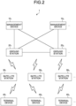
- FIG. 2 is a diagram illustrating a configuration example of the communication system 1 according to the embodiment of the present disclosure.
- the communication system 1 includes a management device 10, a ground station 20, a satellite station 30, and a terminal device 40.
- the communication system 1 provides a user with a wireless network capable of mobile communication by coordinated operation of wireless communication apparatuses configuring the communication system 1.
- the wireless network of the present embodiment includes, for example, a radio access network and a core network.
- the wireless communication apparatus is an apparatus having a function of wireless communication, and corresponds to the ground station 20, the satellite station 30, and the terminal device 40 in the example in FIG. 2 .
- the communication system 1 may include a plurality of management devices 10, a plurality of ground stations 20, a plurality of satellite stations 30, and a plurality of terminal devices 40.
- the communication system 1 includes management devices 10 1 , 10 2 , and the like as the management device 10, ground stations 20 1 , 20 2 , and the like as the ground station 20.
- the communication system 1 includes satellite stations 30 1 , 30 2 , and the like as the satellite station 30, and terminal devices 40 1 , 40 2 , and 40 3 , and the like as the terminal device 40.
- FIG. 3 is a diagram illustrating an example of the wireless network provided by the communication system 1.
- the ground station 20 (satellite station 30) and a base station 60 configure a cell.
- the cell is an area covered by the wireless communication.
- the cell may be any of a macro cell, a micro cell, a femto cell, or a small cell.
- the communication system 1 may be configured to manage a plurality of cells by a single base station (satellite station), or may be configured to manage one cell by a plurality of base stations.
- the base stations 60 1 and 60 2 configure a terrestrial network TN1
- the base stations 60 3 , 60 4 , and 60 5 configure a terrestrial network TN2.
- the terrestrial network TN1 and the terrestrial network TN2 are, for example, networks operated by a wireless communication carrier such as a telephone company.
- the terrestrial network TN1 and the terrestrial network TN2 may be operated by different wireless communication carriers, or may be operated by the same wireless communication carrier.
- the terrestrial network TN1 and the terrestrial network TN2 may also be regarded as one terrestrial network.
- Each of the terrestrial network TN1 and the terrestrial network TN2 is connected to the core network.
- the base station 60 configuring the terrestrial network TN2 is connected to, for example, a core network CN configured by the management device 10 1 .
- the core network CN is EPC.
- the core network CN is 5GC.
- the core network CN is not limited to the EPC or the 5GC, and may be a core network of another radio access system.
- the terrestrial network TN1 is not connected to the core network, but the terrestrial network TN1 may be connected to the core network CN.
- the terrestrial network TN1 may be connected to a core network (not illustrated) different from the core network CN.
- the core network CN includes a gateway device and a gate exchange, and is connected to a public network PN via the gateway device.
- the public network PN is, for example, a public data network such as the Internet, a regional IP network, or a telephone network (mobile telephone network, fixed telephone network, etc.).
- the gateway device is, for example, a server device connected to the Internet or the regional IP network.
- the gateway exchange is, for example, an exchange connected to a telephone network of a telephone company.
- the management device 10 1 may have a function as the gateway device or the gate exchange.
- Each of the satellite stations 30 and 50 and an aircraft station 70 illustrated in FIG. 3 is the non-ground station such as the satellite station or the aircraft station.
- a satellite station group (or satellite station) configuring the non-terrestrial network is referred to as a spaceborne platform.
- an aircraft station group (or aircraft station) configuring the non-terrestrial network is referred to as an airborne platform.
- the satellite stations 30 1 , 30 2 , and 30 3 configure a spaceborne platform SBP1
- the satellite station 50 1 configures a spaceborne platform SBP2.
- the aircraft station 70 3 configures an airborne platform ABP1.
- the terminal device 40 can communicate with both the ground station and the non-ground station.
- the terminal device 40 1 can communicate with the ground station configuring the terrestrial network TN1.
- the terminal device 40 1 can communicate with the non-ground stations configuring the spaceborne platforms SBP1 and SBP2.
- the terminal device 40 1 can also communicate with the non-ground station configuring the airborne platform ABP1. Note that the terminal device 40 1 may be able to directly communicate with another terminal device 40 (terminal device 40 2 of the example in FIG. 3 ).
- the non-ground station such as the satellite station 30 may be connectable to the terrestrial network or the core network via the relay station.
- the non-ground stations can directly communicate with each other without interposing the relay station.
- the relay station is, for example, an aircraft station or an earth station.
- the aircraft station is a radio station installed on the ground or a mobile body traveling on the ground in order to communicate with the aircraft station.
- the earth station is a radio station located on the earth (including air) in order to communicate with the satellite station (space station).
- the earth station may be a large earth station or a small earth station such as a very small aperture terminal (VSAT).
- VSAT very small aperture terminal
- the earth station may be a VSAT controlled earth station (also referred to as a master station or a HUB station) or a VSAT earth station (also referred to as a slave station).
- the earth station may be a radio station installed in the mobile body moving on the ground.
- the earth station mounted on ship, there is an earth station on board vessels (ESV).
- the earth station may include an aircraft earth station that is installed in an aircraft (including a helicopter) and communicates with the satellite station.
- the earth station may include an aircraft earth station that is installed in the mobile body moving on the ground and communicates with the aircraft earth station via the satellite station.
- the relay station may be a portable movable radio station that communicates with the satellite station or the aircraft station.
- the relay station can be regarded as a part of the communication system 1.
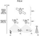
- FIG. 4 is a diagram illustrating an outline of the satellite communication provided by the communication system 1.
- the satellite station is mainly divided into a geostationary earth orbiting satellite station and a low earth orbiting satellite station.
- the geostationary earth orbiting satellite station is located at an altitude of approximately 35786 km and orbits the earth at the same speed as a rotation speed of the earth.
- the satellite station 50 1 configuring the spaceborne platform SBP2 is the geostationary earth orbiting satellite station.
- the geostationary earth orbiting satellite station has almost zero relative velocity with the terminal device 40 on the ground, and is observed as if he geostationary satellite is still from the terminal device 40 on the ground.
- the satellite station 50 1 performs the satellite communication with the terminal devices 40 1 , 40 3 , 40 4 , and the like located on the earth.
- the low earth orbiting satellite station is a satellite station that orbits at a lower altitude than the geostationary earth orbiting satellite station or a medium earth orbiting satellite station.
- the low earth orbiting satellite station is, for example, a satellite station located at an altitude from 500 km to 2000 km.
- the satellite stations 30 2 and 30 3 configuring the spaceborne platform SBP1 are low earth orbiting satellite stations. Note that FIG. 4 illustrates only two satellite stations, namely, the satellite station 30 2 and the satellite station 30 3 , as the satellite stations configuring the spaceborne platform SBP1. However, the spaceborne platform SBP1 is actually configured with two or more (e.g., several tens to several thousands) of satellite stations 30 forming a low earth orbiting satellite constellation.
- the low earth orbiting satellite station has a relative velocity with the terminal device 40 on the ground, and is observed as if the low-orbit satellite station is moving from the terminal device 40 on the ground.
- the satellite stations 30 2 and 30 3 configure respective cells, and perform the satellite communication with terminal devices 40 1 , 40 3 , 40 4 , and the like located on the earth.
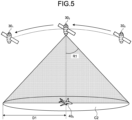
- FIG. 5 is a diagram illustrating an example of a cell configured with a non-geostationary satellite.
- FIG. 5 illustrates a cell C2 formed by the satellite station 30 2 that is the low earth orbiting satellite station.
- the satellite station performing low earth orbiting communicates with the terminal device 40 on the ground with a predetermined directivity on the ground. For example, an angle R1 illustrated in FIG. 5 is 40°.
- a radius D1 of the cell C2 formed by the satellite station 30 2 is, for example, 1000 km.
- the low earth orbiting satellite station moves at a constant velocity. When it becomes difficult for the low earth orbiting satellite station to provide the satellite communication to the terminal device 40 on the ground, a neighbor satellite station provides the satellite communication.
- a neighbor satellite station provides the satellite communication.
- FIG. 5 illustrates a cell C2 formed by the satellite station 30 2 that is the low earth orbiting satellite station.
- the satellite station performing low earth orbiting communicates with the terminal device 40 on the ground with a predetermined directivity on the ground.
- the neighbor satellite station 30 3 when it is difficult for the satellite station 30 2 to provide the satellite communication to the terminal device 40 on the ground, the neighbor satellite station 30 3 provides the satellite communication.
- values of the angle R1 and the radius D1 described above are merely examples and are not limited to the above.
- the medium earth orbiting satellite and the low earth orbiting satellite move on the orbit at a very high speed in the sky, and when the low-orbit satellite is located, for example, at an altitude of 600 km, the low-orbit satellite moves on the orbit at a speed of 7.6 km/S.
- the low earth orbiting satellite forms a cell (or beam) having a radius of several 10 km to several 100 km on the ground, but since the cell formed on the ground also moves in accordance with movement of the satellite, handover may be required even when the terminal device does not move on the ground. For example, assuming a case where a diameter of the cell formed on the ground is 50 km and the terminal device on the ground is not moving, the handover occurs in about 6 to 7 seconds.
- the terminal device 40 can perform the wireless communication using the non-terrestrial network. Furthermore, the satellite station 30 of the communication system 1 configures the non-terrestrial network. As a result, the communication system 1 can extend a service to the terminal device 40 located in an area that cannot be covered by the terrestrial network. For example, the communication system 1 can provide public safety communication and critical communication to a communication apparatus such as an IoT device or a machine type communications (MTC) device. In addition, since service reliability and recoverability are improved by using the non-terrestrial network, the communication system 1 can reduce vulnerability of the service to physical attacks or natural disasters. In addition, the communication system 1 can realize service connection to aircraft terminal devices such as airplane passengers and drones, and service connection to mobile terminal devices such as ships and trains.
- MTC machine type communications
- the communication system 1 can provide A/V content, group communication, an IoT broadcast service, a software download service, a high-efficiency multicast service such as an emergency message, a high-efficiency broadcast service, and the like. Furthermore, the communication system 1 can also realize traffic offloading between the terrestrial network and the non-terrestrial network. In order to realize these, it is desirable that the non-terrestrial network provided by the communication system 1 is subjected to operation integration with the terrestrial network provided by the communication system 1 in an upper layer. In addition, the non-terrestrial network provided by the communication system 1 desirably has the radio access system common to that of the terrestrial network provided by the communication system 1.
- devices in the drawings may be considered as devices in a logical sense.
- a part of the devices in the drawing may be realized by a virtual machine (VM), a container, a docker, or the like, and they may be implemented on physically the same hardware.
- VM virtual machine
- the ground station can be rephrased as the base station.
- the satellite station can be rephrased as the relay station.
- the satellite station can be rephrased as the base station.
- an LTE base station may be referred to as an evolved node B (eNodeB) or an eNB.
- an NR base station may be referred to as a gNodeB or a gNB.
- the terminal device also referred to as a mobile station or a terminal
- UE user equipment
- the terminal device is a type of communication apparatus, and is also referred to as a mobile station or a terminal.
- the concept of the communication apparatus includes not only a portable mobile device (terminal device) such as a mobile terminal but also a device installed in a structure or a mobile body.
- the structure or the mobile body itself may be regarded as the communication apparatus.
- the concept of the communication apparatus includes not only the terminal device but also the base station and the relay device.
- the communication apparatus is one type of processor and information processor.
- the communication apparatus can be rephrased as a transmission device or a reception device.
- each device configuring the communication system 1
- the configuration of each device described below is merely an example.
- the configuration of each device may be different from the following configuration.
- the management device 10 manages the wireless network.
- the management device 10 is a device that manages communication of the ground station 20.
- the management device 10 is, for example, a device having a function as a mobility management entity (MME).
- MME mobility management entity
- the management device 10 is, for example, a device having a function as an access and mobility management function (AMF) or a session management function (SMF).
- AMF access and mobility management function
- SMF session management function
- functions of the management device 10 are not limited to the MME, the AMF, and the SMF.
- the management device 10 may be a device having a function as a network slice selection function (NSSF), an authentication server function (AUSF), or a unified data management (UDM). Furthermore, the management device 10 may be a device having a function as a home subscriber server (HSS).
- NSSF network slice selection function
- AUSF authentication server function
- UDM unified data management
- HSS home subscriber server
- the management device 10 may have a function of the gateway.
- the management device 10 may have a function as a serving gateway (S-GW) or a packet data network gateway (P-GW).
- S-GW serving gateway
- P-GW packet data network gateway
- the management device 10 may have a function as a user plane function (UPF).
- the management device 10 is not necessarily a device configuring the core network.
- W-CDMA wideband code division multiple access
- cdma2000 code division multiple access 2000
- the management device 10 may be a device that functions as a radio network controller (RNC).
- RNC radio network controller
- FIG. 6 is a diagram illustrating a configuration example of the management device 10 according to the embodiment of the present disclosure.
- the management device 10 includes a communication unit 11, a storage unit 12, and a control unit 13. Note that the configuration illustrated in FIG. 6 is a functional configuration, and a hardware configuration may be different from the functional configuration. Furthermore, functions of the management device 10 may be implemented in a distributed manner in a plurality of physically separated structures. For example, the management device 10 may include a plurality of server devices.
- the communication unit 11 is a communication interface for communicating with other devices.
- the communication unit 11 may be a network interface or a device connection interface.
- the communication unit 11 may be a local area network (LAN) interface such as a network interface card (NIC), or may be a universal serial bus (USB) interface including a USB host controller and a USB port.
- LAN local area network
- NIC network interface card
- USB universal serial bus
- the communication unit 11 may be a wired interface or a wireless interface.
- the communication unit 11 functions as a communication means of the management device 10.
- the communication unit 11 communicates with the ground station 20 and the like under the control of the control unit 13.
- the storage unit 12 is a data readable/writable storage device such as a dynamic random access memory (DRAM), a static random access memory (SRAM), a flash memory, or a hard disk.
- the storage unit 12 functions as a storage means of the management device 10.
- the storage unit 12 stores, for example, a connection state of the terminal device 40.
- the storage unit 12 stores an RRC state and an ECM state of the terminal device 40.
- the storage unit 12 may function as a home memory that stores position information of the terminal device 40.
- the control unit 13 is a controller that controls each part of the management device 10.
- the control unit 13 is realized by, for example, a processor such as a central processing unit (CPU) or a micro processing unit (MPU).
- the control unit 13 is implemented by a processor executing various programs stored in the storage device inside the management device 10 using a random access memory (RAM) or the like as a work area.
- the control unit 13 may be realized by an integrated circuit such as an application specific integrated circuit (ASIC) or a field programmable gate array (FPGA). Any of the CPU, the MPU, the ASIC, and the FPGA can be regarded as the controller.
- ASIC application specific integrated circuit
- FPGA field programmable gate array
- the ground station 20 is a wireless communication apparatus that wirelessly communicates with the terminal device 40 via the satellite station 30. Note that the ground station 20 may be configured to communicate with the terminal device 40 without passing through the satellite station 30.
- the ground station 20 is one type of communication apparatus.
- the ground station 20 is, for example, a device corresponding to a wireless base station (e.g., base station, Node B, eNB, and gNB) or a radio access point.
- the ground station 20 may be a wireless relay station.
- the ground station 20 may be an optical extended device called a remote radio head (RRH).
- the ground station 20 may be a receiving station such as a field pickup unit (FPU).
- the ground station 20 may be an integrated access and backhaul (IAB) donor node or an IAB relay node that provides a radio access line and a radio backhaul line by time division multiplexing, frequency division multiplexing, or space division multiplexing.
- IAB integrated access and backhaul
- the radio access technology used by the ground station 20 may be a cellular communication technology or a wireless LAN technology. Obviously, the radio access technology used by the ground station 20 is not limited thereto, and may be other radio access technologies. For example, the radio access technology used by the ground station 20 may be an LPWA communication technology. In addition, the wireless communication used by the ground station 20 may be wireless communication using millimeter waves. Furthermore, the wireless communication used by the ground station 20 may be wireless communication using radio waves or wireless communication (optical) using infrared rays or visible light.
- the ground station 20 may be capable of non-orthogonal multiple access (NOMA) communication with the terminal device 40.
- NOMA communication is communication using a non-orthogonal resource (transmission, reception, or both).
- the ground station 20 may be capable of the NOMA communication with another ground station 20.
- the ground station 20 may be capable of communicating with each other via a base station-core network interface (e.g., S1 interface). This interface may be either wired or wireless.
- the base stations may be capable of communicating with each other via an inter-base station interface (e.g., X2 interface and S1 interface). This interface may be either wired or wireless.
- the concept of the base station includes not only a donor base station but also a relay base station (also referred to as the relay station).
- the concept of the base station includes not only a structure having a function of the base station but also an apparatus installed in the structure.
- the structure is, for example, a building such as a high-rise building, a house, a steel tower, a station facility, an airport facility, a harbor facility, or a stadium.
- the concept of the structure includes not only a building but also a non-building structure such as a tunnel, a bridge, a dam, a wall, or an iron pillar, and equipment such as a crane, a gate, or a windmill.
- the concept of the structure includes not only a structure on land (on the ground in a narrow sense) or underground, but also a structure on water such as a platform or a megafloat, and a structure under water such as a marine observation facility.
- the base station can be rephrased as an information processor.
- the ground station 20 may be a donor station or the relay station. Furthermore, the ground station 20 may be a fixed station or a mobile station.
- the mobile station is a wireless communication apparatus (e.g., base station) configured to be movable.
- the ground station 20 may be a device installed in the mobile body or may be the mobile body itself.
- the relay station having mobility can be regarded as the ground station 20 as the mobile station.
- a device that originally has the mobility such as a vehicle, a drone, or a smartphone, and has a function of the base station (at least a part of the function of the base station) is also the ground station 20 as the mobile station.
- the mobile body may be a mobile terminal such as a smartphone or a mobile phone.
- the mobile body may be a mobile body that travels on land (ground in a narrow sense) (e.g., vehicle including an automobile, a bicycle, a bus, a truck, a motorcycle, a train, and a linear motor car) or a mobile body that travels underground (e.g., inside tunnel) (e.g., subway).
- land ground in a narrow sense
- vehicle including an automobile, a bicycle, a bus, a truck, a motorcycle, a train, and a linear motor car
- a mobile body that travels underground e.g., inside tunnel
- subway e.g., subway
- the mobile body may be a mobile body that travels on water (e.g., ship such as a passenger ship, a cargo ship, or a hovercraft) or a mobile body that moves under water (e.g., submersibles such as a submersible vessel, a submarine, and an unmanned submarine).
- ship such as a passenger ship, a cargo ship, or a hovercraft
- submersibles such as a submersible vessel, a submarine, and an unmanned submarine.
- the mobile body may be a mobile body (e.g., an aircraft such as an airplane, an airship, or a drone) that moves in the atmosphere.
- a mobile body e.g., an aircraft such as an airplane, an airship, or a drone
- the ground station 20 may be a ground base station (ground station) installed on the ground.
- the ground station 20 may be a base station installed in a structure on the ground, or may be a base station installed in a mobile body moving on the ground.
- the ground station 20 may be an antenna installed in a structure such as a building and a signal processing device connected to the antenna.
- the ground station 20 may be a structure or a mobile body itself.
- the "ground” in a broad sense includes not only land (ground in a narrow sense) but also underground, on water, and under water.
- the ground station 20 is not limited to the ground base station.
- the ground station 20 may be the aircraft station. From a viewpoint of the satellite station 30, the aircraft station located on the earth can also be regarded as the ground station.
- the aircraft station is a wireless communication apparatus capable of floating in the atmosphere, such as an aircraft.
- the aircraft station may be a device mounted on an aircraft or the like, or may be the aircraft itself.
- the concept of the aircraft includes not only a heavy aircraft such as an airplane and a glider but also a light aircraft such as a balloon and an airship.
- the concept of the aircraft includes not only heavy and light aircrafts but also a rotorcraft such as a helicopter and an autogyroscope.
- the aircraft station (or the aircraft on which an aircraft station is mounted) may be an unmanned aerial vehicle such as a drone.
- the concept of the unmanned aerial vehicle also includes an unmanned aircraft system (UAS) and a tethered UAS.
- UAS unmanned aircraft system
- the concept of the unmanned aerial vehicle also includes lighter than air (LTA) UAS and heavier than air (HTA) UAS.
- LTA lighter than air
- HTA heavier than air
- the concept of unmanned aerial vehicles also includes high altitude UAS platforms (HAPs).
- a magnitude of coverage of the ground station 20 may be large such as a macro cell to small such as a pico cell. It is apparent that the magnitude of coverage of the ground station 20 may be extremely small such as a femto cell. Further, the ground station 20 may have a beamforming capability. In this case, the ground station 20 may form a cell or a service area for each beam.
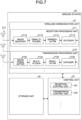
- FIG. 7 is a diagram illustrating a configuration example of the ground station 20 according to the embodiment of the present disclosure.
- the ground station 20 includes a wireless communication unit 21, a storage unit 22, and a control unit 23. Note that the configuration illustrated in FIG. 7 is a functional configuration, and a hardware configuration may be different from the functional configuration. Furthermore, functions of the ground station 20 may be implemented in a distributed manner in a plurality of physically separated configurations.
- the wireless communication unit 21 is a signal processing unit for wirelessly communicating with other wireless communication apparatus (e.g., terminal device 40).
- the wireless communication unit 21 operates under the control of the control unit 23.
- the wireless communication unit 21 corresponds to one or a plurality of radio access systems.
- the wireless communication unit 21 supports both NR and LTE.
- the wireless communication unit 21 may be compatible with W-CDMA or cdma2000 in addition to the NR or LTE.
- the wireless communication unit 21 may support an automatic retransmission technology such as hybrid automatic repeat request (HARQ).
- HARQ hybrid automatic repeat request
- the wireless communication unit 21 includes a reception processing unit 211, a transmission processing unit 212, and an antenna 213.
- the wireless communication unit 21 may include a plurality of reception processing units 211, a plurality of transmission processing units 212, and a plurality of antennas 213.
- each part of the wireless communication unit 21 can be configured individually for each of the radio access systems.
- the reception processing unit 211 and the transmission processing unit 212 may be individually configured for the LTE and the NR.
- the antenna 213 may include a plurality of antenna elements (e.g., a plurality of patch antennas).
- the wireless communication unit 21 may be configured to be beamformable.
- the wireless communication unit 21 may be configured to be able to perform polarization beamforming using vertically polarized waves (V-polarized waves) and horizontally polarized waves (H-polarized waves).
- the reception processing unit 211 processes an uplink signal received via the antenna 213.
- the reception processing unit 211 performs, with respect to the uplink signal, down-conversion, removal of an unnecessary frequency component, control of an amplification level, quadrature demodulation, conversion into a digital signal, removal of a guard interval (cyclic prefix), extraction of a frequency domain signal by fast Fourier transform, and the like.
- the reception processing unit 211 separates an uplink channel, such as a physical uplink shared channel (PUSCH) and a physical uplink control channel (PUCCH), and an uplink reference signal from a signal after the above processing is performed.
- PUSCH physical uplink shared channel
- PUCCH physical uplink control channel
- the reception processing unit 211 demodulates a reception signal using a modulation scheme such as binary phase shift keying (BPSK) or quadrature phase shift keying (QPSK) with respect to a modulation symbol of the uplink channel.
- the modulation scheme used for demodulation may be 16-quadrature amplitude modulation (16QAM), 64QAM, or 256QAM. In this case, signal points on constellation do not necessarily have to be equidistant.
- the constellation may be a non-uniform constellation (NUC).
- the reception processing unit 211 decodes encoded bits of a demodulated uplink channel. Decoded uplink data and uplink control information are output to the control unit 23.
- the transmission processing unit 212 performs transmission processing of downlink control information and downlink data.
- the transmission processing unit 212 encodes the downlink control information and the downlink data input from the control unit 23 using an encoding system such as block encoding, convolutional encoding, or turbo encoding. Then, the transmission processing unit 212 modulates coded bits by a predetermined modulation scheme such as BPSK, QPSK, 16QAM, 64QAM, or 256QAM. In this case, signal points on constellation do not necessarily have to be equidistant.
- the constellation may be a non-uniform constellation.
- the transmission processing unit 212 multiplexes a modulation symbol of each channel and a downlink reference signal, and arranges a multiplexed result in a predetermined resource element. Then, the transmission processing unit 212 performs various types of signal processing on the multiplexed signal under the control of the control unit 23. For example, the transmission processing unit 212 performs processing such as conversion into a frequency domain by fast Fourier transform, addition of cyclic prefix (guard interval), generation of a baseband digital signal, conversion into an analog signal, quadrature modulation, up-conversion, removal of an extra frequency component, and power amplification. A signal generated by the transmission processing unit 212 is transmitted from the antenna 213.
- the antenna 213 is an antenna device (antenna unit) that mutually converts a current and a radio wave.
- the antenna 213 may include one antenna element (e.g., one patch antenna) or may include a plurality of antenna elements (e.g., a plurality of patch antennas).
- the wireless communication unit 21 may be configured to be beamformable.
- the wireless communication unit 21 may be configured to generate a directional beam by controlling the directivity of a radio signal using the plurality of antenna elements.
- the antenna 213 may be a dual-polarized antenna.
- the wireless communication unit 21 may use vertically polarized waves (V-polarized waves) and horizontally polarized waves (H-polarized waves) to transmit radio signals. Then, the wireless communication unit 21 may control directivity of the radio signal transmitted using the vertically polarized wave and the horizontally polarized wave.
- V-polarized waves vertically polarized waves
- H-polarized waves horizontally polarized waves
- the storage unit 22 is a storage device capable of reading and writing data, such as a DRAM, an SRAM, a flash memory, or a hard disk.
- the storage unit 22 functions as a storage means of the ground station 20.
- the control unit 23 is a controller that controls each part of the ground station 20.
- the control unit 23 is realized by, for example, a processor such as a central processing unit (CPU) or a micro processing unit (MPU).
- the control unit 23 is implemented by a processor executing various programs stored in the storage device inside the ground station 20 using the random access memory (RAM) or the like as a work area.
- the control unit 23 may be realized by an integrated circuit such as an application specific integrated circuit (ASIC) or a field programmable gate array (FPGA). Any of the CPU, the MPU, the ASIC, and the FPGA can be regarded as the controller.
- ASIC application specific integrated circuit
- FPGA field programmable gate array
- the control unit 23 includes a reception control unit 231 and a transmission control unit 232.
- Each block (reception control unit 231 and transmission control unit 232) configuring the control unit 23 is a functional block indicating each function of the control unit 23.
- These functional blocks may be software blocks or hardware blocks.
- each of the functional blocks described above may be one software module realized by software (including microprogram), or may be one circuit block on a semiconductor chip (die). It is apparent that each functional block may be one processor or one integrated circuit.
- the control unit 23 may be configured by a functional unit different from the above-described functional blocks. A configuration method of the functional blocks is arbitrary.
- the satellite station 30 is a relay station that relays communication between the ground station 20 and the terminal device 40.
- the satellite station 30 may be a base station that provides the terminal device 40 with a function of the base station.
- the satellite station 30 is the wireless communication apparatus capable of floating outside the atmosphere.
- the satellite station 30 may be a device mounted on a space mobile body such as an artificial satellite, or may be the space mobile body itself.
- the space mobile body is a mobile body that moves outside the atmosphere. Examples of the space mobile body include artificial bodies such as an artificial satellite, spacecraft, space station, and probe.
- a satellite serving as the satellite station 30 may be any of a low earth orbiting (LEO) satellite, a medium earth orbiting (MEO) satellite, a geostationary earth orbiting (GEO) satellite, and a highly elliptical orbiting (HEO) satellite.
- LEO low earth orbiting
- MEO medium earth orbiting
- GEO geostationary earth orbiting
- HEO highly elliptical orbiting
- the satellite station may be a device mounted on the LEO satellite, the MEO satellite, the GEO satellite, or the HEO satellite.
- FIG. 8 is a diagram illustrating a configuration example of the satellite station 30 according to the embodiment of the present disclosure.
- the satellite station 30 includes a wireless communication unit 31, a storage unit 32, and a control unit 33.
- the configuration illustrated in FIG. 8 is a functional configuration, and a hardware configuration may be different from the functional configuration.
- functions of the satellite station 30 may be implemented in a distributed manner in a plurality of physically separated configurations.
- the wireless communication unit 31 is a wireless communication interface that wirelessly communicates with other wireless communication apparatuses (e.g., ground station 20, terminal device 40, satellite station 50, and another satellite station 30).
- the wireless communication unit 31 supports one or a plurality of radio access systems.
- the wireless communication unit 31 supports both NR and LTE.
- the wireless communication unit 31 may be compatible with the W-CDMA or cdma3000 in addition to the NR or LTE.
- the wireless communication unit 31 includes a reception processing unit 311, a transmission processing unit 312, and an antenna 313.
- the wireless communication unit 31 may include a plurality of reception processing units 311, a plurality of transmission processing units 312, and a plurality of antennas 313.
- each part of the wireless communication unit 31 can be configured individually for each radio access system.
- the reception processing unit 311 and the transmission processing unit 312 may be individually configured for the LTE and the NR.
- Configurations of the reception processing unit 311, the transmission processing unit 312, and the antenna 313 are similar to the configurations of the reception processing unit 311, the transmission processing unit 312, and the antenna 313 described above.
- the wireless communication unit 31 may be configured to be beamformable similarly to the wireless communication unit 21.
- the storage unit 32 is a storage device capable of reading and writing data, such as the DRAM, the SRAM, the flash memory, or the hard disk.
- the storage unit 32 functions as a storage means of the satellite station 30.
- the control unit 33 is a controller that controls each part of the satellite station 30.
- the control unit 33 is realized by, for example, a processor such as the CPU or the MPU.
- the control unit 33 is realized by a processor executing various programs stored in the storage device inside the satellite station 30 using the RAM or the like as a work area.
- the control unit 33 may be realized by an integrated circuit such as the ASIC or the FPGA. Any of the CPU, the MPU, the ASIC, and the FPGA can be regarded as the controller.
- the control unit 33 includes a reception control unit 331 and a transmission control unit 332.
- Each block (reception control unit 331 and transmission control unit 332) configuring the control unit 33 is a functional block indicating each function of the control unit 33.
- These functional blocks may be software blocks or hardware blocks.
- each of the functional blocks described above may be one software module realized by software (including microprogram), or may be one circuit block on a semiconductor chip (die). It is apparent that each functional block may be one processor or one integrated circuit.
- the control unit 33 may be configured by a functional unit different from the above-described functional blocks. A configuration method of the functional blocks is arbitrary.
- the terminal device 40 is a wireless communication apparatus that wirelessly communicates with other communication apparatuses such as the ground station 20, the satellite stations 30 and 50, the base station 60, and the aircraft station 70.
- the terminal device 40 may be a mobile phone, a smart device (smartphone or tablet), a personal digital assistant (PDA), or a personal computer.
- the terminal device 40 may be a device such as a business-use camera provided with a communication function, or may be a motorcycle, a moving relay vehicle, or the like on which a communication apparatus such as a field pickup unit (FPU) is mounted.
- the terminal device 40 may be a machine to machine (M2M) device or an Internet of things (IoT) device.
- M2M machine to machine
- IoT Internet of things
- the terminal device 40 may be capable of performing NOMA communication with the ground station 20. Furthermore, the terminal device 40 may be capable of using an automatic retransmission technology such as HARQ when communicating with the ground station 20. Further, the terminal device 40 may be capable of performing sidelink communication with another terminal device 40. The terminal device 40 may also be capable of using an automatic retransmission technology such as HARQ when performing the sidelink communication. Note that the terminal device 40 may also be capable of NOMA communication in communication (sidelink) with other terminal devices 40. Furthermore, the terminal device 40 may be capable of performing the LPWA communication with another communication apparatus (e.g., ground station 20 and other terminal devices 40). Furthermore, wireless communication used by the terminal device 40 may be wireless communication using millimeter waves. Note that the wireless communication (including sidelink communication) used by the terminal device 40 may be wireless communication using radio waves or wireless communication (optical) using infrared rays or visible light.
- the terminal device 40 may be a mobile device.
- the mobile device is a mobile wireless communication apparatus.
- the terminal device 40 may be a wireless communication apparatus installed in a mobile body or may be the mobile body itself.
- the terminal device 40 may be a vehicle that moves on a road, such as an automobile, a bus, a truck, and a motorcycle, or the wireless communication apparatus mounted on the vehicle.
- the mobile body may be a mobile terminal, or may be the mobile body that travels on land (on the ground in a narrow sense), underground, on water, or under water.
- the mobile body may be a mobile body that travels in the atmosphere, such as a drone or a helicopter, or may be a mobile body that travels outside the atmosphere such as an artificial satellite.
- the terminal device 40 may be simultaneously connected to a plurality of base stations or a plurality of cells to perform communication. For example, when one base station supports a communication area via a plurality of cells (e.g., pCell and sCell), it is possible to bundle the plurality of cells and communicate between the ground station 20 and the terminal device 40 by a carrier aggregation (CA) technology, a dual connectivity (DC) technology, or a multi-connectivity (MC) technology. Alternatively, the terminal device 40 and the plurality of ground stations 20 can communicate with each other by a coordinated multi-point transmission and reception (CoMP) technology via cells of different ground stations 20.
- CA carrier aggregation
- DC dual connectivity
- MC multi-connectivity
- the terminal device 40 and the plurality of ground stations 20 can communicate with each other by a coordinated multi-point transmission and reception (CoMP) technology via cells of different ground stations 20.
- CoMP coordinated multi-point transmission and reception
- FIG. 9 is a diagram illustrating a configuration example of the terminal device 40 according to the embodiment of the present disclosure.
- the terminal device 40 includes a wireless communication unit 41, a storage unit 42, and a control unit 43.
- the configuration illustrated in FIG. 9 is a functional configuration, and a hardware configuration may be different from the functional configuration.
- functions of the terminal device 40 may be implemented in a distributed manner in a plurality of physically separated configurations.
- the wireless communication unit 41 is a signal processing unit for wirelessly communicating with other wireless communication apparatuses (e.g., ground station 20, and other terminal devices 40).
- the wireless communication unit 41 operates under the control of the control unit 43.
- the wireless communication unit 41 includes a reception processing unit 411, a transmission processing unit 412, and an antenna 413. Configurations of the wireless communication unit 41, the reception processing unit 411, the transmission processing unit 412, and the antenna 413 may be similar to those of the wireless communication unit 21, the transmission processing unit 212, the reception processing unit 211, and the antenna 213 of the ground station 20. Further, the wireless communication unit 41 may be configured to be beamformable similarly to the wireless communication unit 21.
- the storage unit 42 is a storage device capable of reading and writing data, such as a DRAM, an SRAM, a flash memory, or a hard disk.
- the storage unit 42 functions as a storage means of the terminal device 40.
- the control unit 43 is a controller that controls each part of the terminal device 40.
- the control unit 43 is realized by, for example, a processor such as the CPU or the MPU.
- the control unit 43 is realized by a processor executing various programs stored in a storage device inside the terminal device 40 using the RAM or the like as a work area.
- the control unit 43 may be realized by an integrated circuit such as the ASIC or the FPGA. Any of the CPU, the MPU, the ASIC, and the FPGA can be regarded as the controller.
- the control unit 43 includes a reception control unit 431 and a transmission control unit 432.
- Each block (reception control unit 431 and transmission control unit 432) configuring the control unit 43 is a functional block indicating each function of the control unit 43.
- These functional blocks may be software blocks or hardware blocks.
- each of the functional blocks described above may be one software module realized by software (including microprogram), or may be one circuit block on a semiconductor chip (die). It is apparent that each functional block may be one processor or one integrated circuit.
- the control unit 43 may be configured by a functional unit different from the above-described functional blocks. A configuration method of the functional blocks is arbitrary.
- FIG. 10 is a diagram illustrating an example of a frame configuration of the transmission signal according to the embodiment of the present disclosure.
- FIG. 10 illustrates a frame configuration of one subframe.
- one subframe is 1 ms.
- a plurality of symbols is included in one subframe.
- one subframe includes 15 symbols.
- Each symbol includes one piece of transmission data.
- One subframe includes a plurality of consecutive symbols including the same transmission data.
- a length of the transmission data (example of a first signal) and a length of a signal obtained by adding the cyclic prefix CP to the transmission data are one transmission unit (symbol).
- the transmission data is a signal converted from the frequency domain to the time domain by inverse fast Fourier transform (IFFT).
- IFFT inverse fast Fourier transform
- the transmission data may also be referred to as, for example, a time-continuous signal or a time-continuous signal without cyclic prefix.
- the cyclic prefix CP is added to the head of the transmission data #1_1 and #2_1 transmitted for the first time, and the cyclic prefix CP is not added to other pieces of transmission data #1_2 to #1_8 and #2_2 to #2_7.
- a symbol length T11 of symbols including the transmission data #1_1 and #2_1 transmitted for the first time is longer than symbol lengths T12 and T13 of symbols including other pieces of transmission data #1_2 to #1_8 and #2_2 to #2_7.
- the symbol length T13 of the symbol including the transmission data #2_7 transmitted at the end of the subframe is shorter than the symbol lengths T11 and T12 of the symbols including other pieces of transmission data #1_1 to #1_8 and #2_1 to #2_6.
- the cyclic prefix CP is added to the transmission data #1_1 and #2_1.
- the length of the last symbol of the subframe is shorter than the data length of the transmission data, the length of the last symbol of the subframe is shorter than the lengths of all other symbols. Therefore, the length of the transmission data #2_7 included in the last symbol is shorter than the lengths of the other pieces of transmission data #1_1 to #1_8 and #2_1 to #2_6.
- the last symbol includes the transmission data #2_7, but the present disclosure is not limited thereto.
- the last symbol may include a zero-padding signal instead of the transmission data #2_7.
- two pieces of transmission data #1 and #2 are included in one subframe, but the present disclosure is not limited thereto.
- One piece of transmission data #1 may be repeated and concatenated in one subframe.
- three or more pieces of transmission data #1, #2, #3, and so on may be included in one subframe.
- At least one piece of transmission data included in one subframe may be repeated and concatenated a plurality of times.
- one subframe may include one or more pieces of transmission data of which the number of times of concatenation is two or more, and the number of times of concatenation of one piece of transmission data may be six times or less or nine times or more.
- one piece of transmission data #2 may be included in the subframe.
- FIG. 10 illustrates a case where the cyclic prefix CP is added to the heads of the transmission data #1_1 and #2_1 transmitted for the first time, but the present disclosure is not limited thereto.
- the cyclic prefix CP may be added to ends of the transmission data #1_8 and #2_7 that are transmitted last.
- the configuration as illustrated in FIG. 10 may be defined in advance according to standards or the like, or may be set by the base station.
- the base station may determine at least one of the following settings for repetitive transmission according to the embodiment.
- the base station determines whether or not to perform the repetitive transmission according to, for example, capability and position information of the terminal device 40. At this time, the base station may determine whether to perform the repetitive transmission according to the present embodiment or, for example, whether to perform the conventional repetitive transmission illustrated in FIG. 1A .
- the base station determines, for example, the number of times to perform repetitive transmission for one piece of transmission data (number of times of repetitive transmission).
- the number of times of repetitive transmission can be determined according to, for example, the position information of the terminal device 40 or availability of resource.
- the base station determines the number of times of concatenation that is the number of times of repeating one piece of transmission data for concatenation.
- the number of times of concatenation may be the same as or less than the number of times of repetitive transmission.
- the base station determines the insertion position of the cyclic prefix CP.
- the base station may, for example, determine to insert the cyclic prefix CP at a timing when the transmission data is switched. In other words, the base station may determine to insert the cyclic prefix CP into one symbol in each concatenated data. Alternatively, the base station may determine to insert the cyclic prefix CP at a specific timing at which the transmission unit in time axis, such as a slot or the subframe, is changed.
- the base station may determine to insert the cyclic prefix CP at the timing when the subframe is changed in addition to the timing when the transmission data is changed.
- the base station determines the size of the cyclic prefix CP.
- the size of the cyclic prefix CP is determined according to a radio wave propagation path delay status of the communication system 1.
- the size of the cyclic prefix CP may also include zero. In other words, the cyclic prefix CP may not be inserted, or the cyclic prefix CP having the size of zero may be inserted.
- the above-described setting is set by the base station, but is not limited thereto.
- all or some of the settings may be determined in advance according to standards or the like, or may be determined according to the state of the communication system 1 or other settings.
- the insertion position of the cyclic prefix CP is also determined according to the number of times of concatenation when the base station determines the number of times of transmission data concatenation.
- the number of times of concatenation is determined accordingly.
- each of the terminal device 40 and the base station may calculate the number of times of repetitive transmission according to a propagation distance estimated according to a position of the base station and a position of the terminal device 40.
- the base station determines the number of times of repetitive transmission or the number of times of concatenation, so that the other is also determined.
- the base station notifies, by signaling, the terminal device 40 of information regarding the determined setting.
- the base station notifies the terminal device 40 of setting information regarding the repetitive transmission by using, for example, system information or RRC signaling.
- the base station can also notify the terminal device 40 of, for example, a timing to change the transmission data to be concatenated. Specifically, for example, the base station can notify the terminal device 40 of information regarding the timing at which the transmission data #1 is changed to the transmission data #2.
- the base station may notify the terminal device 40 of information regarding subcarrier spacing.
- the terminal device 40 may change a value of the setting information (information regarding the number of times of repetitive transmission and the number of times of concatenation, information regarding the insertion position/size of the cyclic prefix CP, etc.) regarding the above-described repetitive transmission of the present embodiment according to the information regarding subcarrier spacing.
- the base station notifies the setting information regarding the repetitive transmission of the present embodiment (hereinafter also simply referred to as setting information.) when the subcarrier spacing of 15 kHz is used as a basis.
- the terminal device 40 calculates a value of the setting information in subcarrier spacing notified according to the setting information and the information regarding subcarrier spacing notified separately from the base station.
- the case where the subcarrier spacing of 15 kHz is used as the basis has been described as an example, but the value is not limited thereto, and other subcarrier spacing values may be used as the basis.
- the base station may explicitly or implicitly notify implementation information regarding whether or not to implement the repetitive transmission of the present embodiment.
- the terminal device 40 When the base station explicitly notifies the implementation information, the terminal device 40 performs, for example, signal processing to which the repetitive transmission according to the present embodiment is applied in both a transmission process and a reception process. Note that details of the transmission process and the reception process performed by the base station and the terminal device 40 will be described later.
- the base station may notify the implementation information in association with the information regarding whether or not to perform the repetitive transmission. For example, when the repetitive transmission is performed, the repetitive transmission according to the embodiment is performed, and when the repetitive transmission is not performed, the repetitive transmission according to the embodiment is not performed.
- the base station may notify the implementation information in association with the number of times of repetitive transmission. For example, when the repetitive transmission is performed a predetermined number of times of repetition or more, the repetitive transmission of the present embodiment is performed. On the other hand, when transmission is performed less than the predetermined number of times of repetition, the repetitive transmission of the present embodiment is not performed, and general repetitive transmission, for example, as illustrated in FIG. 1A is performed. Note that the number of times of repetitive transmission may be explicitly notified to the terminal device 40 by the base station, or may be determined based on information regarding a distance between the base station and the terminal device 40.
- the base station may notify the implementation information in association with information regarding a guard interval such as the cyclic prefix CP. For example, when the base station notifies the position information regarding the insertion position of the guard interval, such as the cyclic prefix CP, the repetitive transmission according to the embodiment is performed. On the other hand, when the position information is not notified, the repetitive transmission of the present embodiment is not performed.
- a guard interval such as the cyclic prefix CP
- the transmission process is performed by the transmission processing unit 212 under the control of the control unit 23 (transmission control unit 232) of the ground station 20 described above.
- the transmission process is performed by the transmission processing unit 312 under the control of the control unit 33 (transmission control unit 332) of the satellite station 30.
- the transmission process is performed by the transmission processing unit 412 under the control of the control unit 43 (transmission control unit 432) of the terminal device 40.
- a control unit of a transmission device performs the transmission process.
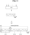
- FIG. 11 is a diagram illustrating an example of the transmission process according to the embodiment of the present disclosure.
- the control unit of the transmission device performs a fast Fourier transform (IFFT) process on the transmission data in the frequency domain to generate the transmission data #1 in the time domain.
- IFFT fast Fourier transform
- the control unit of the transmission device duplicates the transmission data #1 according to the number of times of concatenation to generate and concatenate the transmission data #1_1 to #1_3.
- the control unit of the transmission device adds the cyclic prefix CP to the head of the concatenated transmission data to generate a transmission signal.
- the control unit of the transmission device transmits the transmission signal generated to a reception device that is a communication partner.
- control unit of the transmission device concatenates a plurality of signals (transmission data) obtained by IFFT, and inserts the cyclic prefix CP at the head of the concatenated transmission data.
- the cyclic prefix CP is not inserted between the concatenated pieces of transmission data. This is because, as illustrated in FIG. 11 , since a time-axis signal waveform of the concatenated transmission data is a continuous signal waveform (see period T14 in FIG. 11 ), the same effect as that in the case of insertion of the cyclic prefix CP can be obtained although the cyclic prefix CP is not inserted.
- control unit of the transmission device repeats concatenation of the transmission data obtained by the IFFT according to the number of times of concatenation, and inserts the cyclic prefix CP at the head of concatenated signals.
- the reception process is performed by the reception processing unit 211 under the control of the control unit 23 (reception control unit 231) of the ground station 20 described above.
- the reception process is performed by the reception processing unit 311 under the control of the control unit 33 (reception control unit 331) of the satellite station 30.
- the reception process is performed by the reception processing unit 411 under the control of the control unit 43 (reception control unit 431) of the terminal device 40.
- a control unit of a reception device performs the reception process.
- the control unit of the reception device removes a guard interval segment such as the cyclic prefix CP from a reception signal. After the guard interval is removed, the control unit of the reception device cuts out the reception signal by FFT size from the head of a time sample after the removal, and decodes the reception signal into a signal in the frequency domain.
- a guard interval segment such as the cyclic prefix CP
- FIG. 12 is a diagram illustrating the FFT segment of the reception process according to the embodiment of the present disclosure.
- the control unit of the reception device performs decoding of the reception signal in the "FFT" segment by cutting out the reception signal excluding the cyclic prefix CP by FFT size.
- the length of the data (hereinafter also referred to as received data) included in the last symbol may be shorter than the length of the received data included in other symbols.
- the size of received data #2_7 included in the last symbol of one subframe is smaller than the FFT size.
- the control unit of the reception device performs decoding after shifting the start position of the FFT segment forward. As a result, a part of received data #2_6 and received data #2_7 are included in the FFT segment corresponding to the last received data #2_7.
- the received data #2_1 to #2_7 are data in which the same received data #2 is repeated and concatenated, and have a continuous signal waveform. Therefore, even when the start position of the FFT corresponding to the received data #2_7 is shifted forward, the same decoding result as the decoding results of other received data #2_1 to #2_6 can be obtained.
- the control unit of the reception device acquires the number of pieces of received data corresponding to the number of times of concatenation in the time domain.
- the control unit of the reception device calculates a log-likelihood ratio (LLR) for each of a plurality of pieces of received data subjected to FFT after the FFT process, and adds up the plurality of calculated LLRs to reduce an error rate characteristics.
- LLR log-likelihood ratio
- the transmission device transmits the transmission signal generated by concatenating repeated one piece of data, so that the reception device can receive the reception signal having the continuous signal waveform even when the cyclic prefix CP is only added to the head of the data.
- the reception device can perform the FFT process at the time of decoding in an arbitrary FFT segment.
- FIG. 13 is a sequence diagram illustrating an operation of the repetitive transmission of the communication system 1 according to the embodiment of the present disclosure.
- the operation of the communication system 1 in the case of performing the repetitive transmission in the uplink will be described with reference to FIG. 13 .
- the communication system 1 can similarly perform the repetitive transmission also in the downlink.
- FIG. 13 illustrates communication between the base station and the terminal device 40, repetition can be similarly performed in communication between the base station and the relay station and/or communication between the relay station and the terminal device 40.
- the terminal device 40 receives a synchronization signal from the base station (Step S101), and receives system information (Step S102). At this time, the base station may notify the terminal device 40 of semi-static information for performing the repetitive transmission of the present embodiment as the system information.
- the terminal device 40 performs a random access procedure with the base station by using 2-STEP random access, 4-STEP random access, or the like.
- the terminal device 40 performs the random access procedure by transmitting a random access preamble to the base station (Step S103) and receiving a random access response from the base station (Step S104).
- the terminal device 40 transmits an RRC connection request to the base station (Step S105).
- the base station transmits RRC connection setup information to the terminal device 40 (Step S106). Thereafter, the terminal device 40 transmits its own capability information to the base station (Step S107).
- the base station notifies the terminal device 40 of semi-static information by RRC signaling (Step S108).
- the semi-static information includes semi-static configuration information for implementing the repetitive transmission according to the embodiment, such as the number of times of data concatenation.
- the terminal device 40 requests the base station to perform uplink scheduling as necessary (Step S110).
- the base station transmits uplink grant information to the terminal device 40 (Step 5111).
- the uplink grant information may include dynamic setting information for implementing the repetitive transmission according to the present embodiment.
- the terminal device 40 executes the transmission process based on the repetitive transmission according to the present embodiment and generates the transmission signal (Step S112).
- the terminal device 40 transmits the transmission signal (Steps S113 to S115) and executes the repetitive transmission.
- the base station performs the reception process based on the repetitive transmission according to the present embodiment, and decodes the reception signal (Step S116).
- the base station notifies the terminal device 40 of the information regarding the reception result as information regarding retransmission (Step S117).
- the information regarding retransmission includes, for example, information regarding ACK/NACK.
- one symbol includes one piece of transmission data, but the present disclosure is not limited thereto.
- a signal obtained by concatenating repeated transmission data may be one symbol.
- a plurality of pieces of the same transmission data may be included in one symbol.
- FIG. 14 is a diagram illustrating an example of a frame configuration according to a first modification of the embodiment of the present disclosure.
- a plurality of pieces of transmission data #1_1 to #1_8 is included in one symbol, and the cyclic prefix CP is inserted at the head of the symbol.
- a plurality of pieces of transmission data #2_1 to #2_7 is included in one symbol, and the cyclic prefix CP is inserted at the head of the symbol.
- a length of the signal (example of the second signal) obtained by concatenating repeated transmission data is one transmission unit (symbol).
- the frame configuration illustrated in FIG. 14 is the same as the frame configuration illustrated in FIG. 10 except that a definition of the symbol is different. Therefore, the communication system 1 can perform the repetitive transmission similarly to the above-described embodiment.
- FIG. 15 is a diagram illustrating an example of a frame configuration according to a second modification of the embodiment of the present disclosure.
- the number of data samples included in the symbol having the cyclic prefix CP is smaller than the number of data samples so that the lengths of the symbols included in the subframes become equal.
- the length of the transmission data (example of the first signal) and the length of the transmission data including the cyclic prefix CP are one transmission unit (symbol).
- the lengths of a plurality of symbols included in one subframe can be unified to the data length T12.
- the plurality of samples at the head or tail of the symbol may be replaced with the cyclic prefix CP.
- the communication system 1 performs processing assuming that the plurality of samples at the head or tail of the symbol including the cyclic prefix CP is the cyclic prefix CP.
- the control unit of the transmission device adds, as the cyclic prefix CP, the last 160 samples or 144 samples among 2048 data samples obtained by IFFT of the data in the frequency domain to the head of the data.
- the control unit of the transmission device assumes that the first 160 samples or 144 samples among the 2048 data samples obtained by IFFT of the data in the frequency domain are the cyclic prefix CP.
- FIG. 16 is a diagram illustrating the FFT segment according to the second modification of the embodiment of the present disclosure.
- the control unit of the reception device cuts out the reception signal by FFT size from the head of the time sample to decode the reception signal. At this time, the number of samples of the symbol from which the cyclic prefix CP is removed is smaller than the number of samples of other symbols. Therefore, as illustrated in FIG. 16 , data of a plurality of symbols is included in one FFT segment. As described above, since the concatenated data has a continuous signal waveform, the control unit of the reception device can perform a decoding process in the FFT segment over the plurality of symbols.
- the control unit of the reception device adjusts the FFT segment by shifting the start position of the FFT segment forward.
- the control unit of the reception device adjusts the FFT segment by shifting the start position of the FFT segment forward.
- the communication system 1 may perform the repetitive transmission by switching between the frame configuration illustrated in FIG. 10 and the frame configuration illustrated in FIG. 15 .
- the base station notifies the terminal device 40 or the relay station of the information regarding the frame configuration used for the repetitive transmission as the setting information.
- the communication system 1 may perform the repetitive transmission using a plurality of frequency resources.
- frequency hopping may be applied to the repetitive transmission of the present embodiment.
- FIG. 17 is a diagram illustrating the frequency hopping according to a third modification of the embodiment of the present disclosure.
- FIG. 17 illustrates a case where the frequency hopping is applied to the frame configuration illustrated in FIG. 15
- the frequency hopping according to the present modification can also be applied to the frame configurations illustrated in FIGS. 10 and 14 .
- FIG. 17 illustrates a case where the communication system 1 performs the frequency hopping in a first frequency band F1 and a second frequency band F2.
- the control unit of the transmission device repeatedly transmits the data #1 four times in the first frequency band F1, and repeatedly transmits the data #1 four times in the second frequency band F2. Thereafter, the control unit of the transmission device repeatedly transmits the data #2 four times in the first frequency band F1, and repeatedly transmits the data #2 four times in the second frequency band F2.
- the control unit of the transmission device repeatedly transmits the data #1 eight times and the data #2 eight times while hopping between the first and second frequency bands F1 and F2 in one subframe.
- the control unit of the transmission device generates the transmission signal by including the cyclic prefix CP in the first symbol after the frequency hopping (data #1_1, #1_5, #2_1, and #2_5 in FIG. 17 ).
- the control unit of the transmission device divides a signal obtained by concatenating repeated data (data #1_1 to #1_8) into a plurality of signal blocks (e.g., block of data #1_1 to #1_4 and block of data #1_5 to #1_8).
- the control unit of the transmission device transmits each signal block using different frequency bands.
- the cyclic prefix CP is the head (or tail) of the signal block.
- the communication system 1 according to the present modification can obtain effects similar to those of the above-described embodiment and modifications. Furthermore, the communication system 1 according to the present modification can further improve the frequency utilization efficiency by performing the frequency hopping while suppressing interference with other users by adding the cyclic prefix CP to the head (or tail) of the signal block.
- the repetitive transmission of the present embodiment in which the plurality of pieces of data is repeated and concatenated using one subframe as a separator has been described.
- the present disclosure is not limited thereto.
- one slot, a non-slot, or a radio frame may be used as the separator to perform the repetitive transmission of the present embodiment.
- the transmission unit in the time axis in which the repetitive transmission of the present embodiment is performed is not limited to the subframe.
- the repetitive transmission according to the present embodiment can be performed in an arbitrary transmission unit such as the slot or the frame.
- the cyclic prefix CP and the data are included in one symbol, but the present disclosure is not limited thereto.
- data not including the cyclic prefix CP may be used as one symbol.
- control device that controls the transmission device and the reception device of the present embodiment may be realized by a dedicated computer system or a general-purpose computer system.
- a communication program for executing the above-described operation is stored and distributed in a computer-readable recording medium such as an optical disk, a semiconductor memory, a magnetic tape, or a flexible disk. Then, for example, the program is installed on a computer, and the above-described processes are executed to configure the control device.
- the control device may be a device (e.g., personal computer) outside the transmission device or the reception device.
- the control device may be a device (e.g., control unit) inside the transmission device or the reception device.
- the above communication program may be stored in a disk device included in a server device on a network such as the Internet so that the communication program can be downloaded to the computer.
- the above-described functions may be realized by cooperation of an operating system (OS) and application software.
- OS operating system
- application software a portion other than the OS may be stored in a medium and distributed, or a portion other than the OS may be stored in a server device and downloaded to the computer.
- each component of each device illustrated in the drawings is functionally conceptual, and is not necessarily physically configured as illustrated in the drawings.
- a specific form of distribution and integration of each device is not limited to the illustrated form, and all or a part thereof can be functionally or physically distributed and integrated in an arbitrary unit according to various loads, usage conditions, and the like. Note that this configuration by distribution and integration may be performed dynamically.
- the present embodiment can be implemented as any configuration constituting an apparatus or a system, for example, a processor as a system large scale integration (LSI) or the like, a module using a plurality of processors or the like, a unit using a plurality of modules or the like, a set obtained by further adding other functions to a unit, or the like (i.e., configuration of a part of device).
- LSI system large scale integration
- modules using a plurality of processors or the like
- a unit using a plurality of modules or the like a set obtained by further adding other functions to a unit, or the like (i.e., configuration of a part of device).
- the system means a set of a plurality of components (devices, modules (parts), etc.), and it does not matter whether or not all the components are in the same housing. Therefore, a plurality of devices housed in separate housings and connected via a network and one device in which a plurality of modules is housed in one housing are both systems.
- the present embodiments can adopt a configuration of cloud computing in which one function is shared and processed by a plurality of devices in cooperation via a network.
- the present technology can also have the following configurations.
Landscapes
- Engineering & Computer Science (AREA)
- Computer Networks & Wireless Communication (AREA)
- Signal Processing (AREA)
- Mobile Radio Communication Systems (AREA)
Applications Claiming Priority (2)
| Application Number | Priority Date | Filing Date | Title |
|---|---|---|---|
| JP2021076545 | 2021-04-28 | ||
| PCT/JP2022/007953 WO2022230340A1 (ja) | 2021-04-28 | 2022-02-25 | 通信装置及び通信方法 |
Publications (2)
| Publication Number | Publication Date |
|---|---|
| EP4333389A1 true EP4333389A1 (de) | 2024-03-06 |
| EP4333389A4 EP4333389A4 (de) | 2024-07-31 |
Family
ID=83846948
Family Applications (1)
| Application Number | Title | Priority Date | Filing Date |
|---|---|---|---|
| EP22795263.7A Pending EP4333389A4 (de) | 2021-04-28 | 2022-02-25 | Kommunikationsvorrichtung und kommunikationsverfahren |
Country Status (5)
| Country | Link |
|---|---|
| US (1) | US20240121144A1 (de) |
| EP (1) | EP4333389A4 (de) |
| JP (1) | JPWO2022230340A1 (de) |
| CN (1) | CN117256131A (de) |
| WO (1) | WO2022230340A1 (de) |
Family Cites Families (24)
| Publication number | Priority date | Publication date | Assignee | Title |
|---|---|---|---|---|
| US8295266B2 (en) * | 2006-10-25 | 2012-10-23 | Lg Electronics Inc. | Method for adjusting RACH transmission against frequency offset |
| JP4342565B2 (ja) * | 2007-03-08 | 2009-10-14 | 株式会社東芝 | 送信機および受信機 |
| JP2008227586A (ja) * | 2007-03-08 | 2008-09-25 | Toshiba Corp | 送信機および受信機 |
| US9438310B2 (en) * | 2012-02-29 | 2016-09-06 | Texas Instruments Incorporated | Multi-length cyclic prefix for OFDM transmission in PLC channels |
| US9191256B2 (en) * | 2012-12-03 | 2015-11-17 | Digital PowerRadio, LLC | Systems and methods for advanced iterative decoding and channel estimation of concatenated coding systems |
| WO2015026132A1 (en) * | 2013-08-19 | 2015-02-26 | Lg Electronics Inc. | Apparatus for transmitting broadcast signals, apparatus for receiving broadcast signals, method for transmitting broadcast signals and method for receiving broadcast signals |
| WO2015046836A1 (en) * | 2013-09-26 | 2015-04-02 | Lg Electronics Inc. | Apparatus for transmitting signaling information, apparatus for receiving signaling information, method for transmitting signaling information and method for receiving signaling information |
| US20150089382A1 (en) * | 2013-09-26 | 2015-03-26 | Wu-chi Feng | Application context migration framework and protocol |
| WO2016049216A2 (en) * | 2014-09-23 | 2016-03-31 | Marvell Semiconductor, Inc. | Short training field for wifi |
| EP3357292B1 (de) * | 2015-09-28 | 2019-07-10 | Telefonaktiebolaget LM Ericsson (PUBL) | Direktzugriffspräambel zur minimierung von pa-backoff |
| WO2017117424A1 (en) * | 2015-12-31 | 2017-07-06 | Idac Holdings, Inc. | Methods for dynamic management of reference signals |
| TWI707570B (zh) * | 2016-03-30 | 2020-10-11 | 美商Idac控股公司 | 使用唯一字(UW)離散傅立葉轉換展開正交分頻多工(DFT-s-OFDM)增進實體層效率方法及程序 |
| TW201804835A (zh) * | 2016-05-11 | 2018-02-01 | Idac控股公司 | 無線系統中媒體存取協定資料單元組合 |
| US10084562B2 (en) * | 2016-08-22 | 2018-09-25 | Huawei Technologies Co., Ltd. | System and method for filtered OFDM |
| EP3471294A4 (de) * | 2016-09-30 | 2020-02-26 | LG Electronics Inc. -1- | Verfahren zum senden und empfangen von synchronisationssignalen in einem drahtloskommunikationssystem und vorrichtung für das verfahren |
| US10568130B2 (en) * | 2016-12-22 | 2020-02-18 | Qualcomm Incorporated | Techniques and apparatuses for multiple types of physical random access channel (PRACH) transmission utilization |
| JP7018121B2 (ja) * | 2017-11-14 | 2022-02-09 | エルジー エレクトロニクス インコーポレイティド | 時分割デュプレクシングをサポートする狭帯域IoTシステムにおいてランダムアクセスプリアンブルを送信するための方法及びそのための装置 |
| WO2019098681A1 (ko) * | 2017-11-14 | 2019-05-23 | 엘지전자 주식회사 | 시간 분할 듀플렉싱을 지원하는 협대역 iot 시스템에서 랜덤 액세스 프리앰블을 전송하기 위한 방법 및 이를 위한 장치 |
| WO2019150507A1 (ja) * | 2018-01-31 | 2019-08-08 | 三菱電機株式会社 | 送信装置、受信装置および送信方法 |
| EP3675444A1 (de) * | 2018-12-28 | 2020-07-01 | INTEL Corporation | Verfahren und vorrichtungen für kommunikationen in vorrichtung-zu-vorrichtung-netzwerken |
| WO2021035573A1 (en) * | 2019-08-28 | 2021-03-04 | Qualcomm Incorporated | Payload segmentation and resource mapping for gf transmissions |
| CN114556875B (zh) * | 2019-11-01 | 2023-11-17 | 华为技术有限公司 | 符号处理的方法与装置 |
| US12279156B2 (en) * | 2020-06-03 | 2025-04-15 | Mavenir Systems, Inc. | Traffic timing control for an open radio access network in a cloud radio access network system |
| US11617171B2 (en) * | 2020-12-28 | 2023-03-28 | Qualcomm Incorporated | Time gap with tail samples for high frequency bands |
-
2022
- 2022-02-25 EP EP22795263.7A patent/EP4333389A4/de active Pending
- 2022-02-25 US US18/554,807 patent/US20240121144A1/en active Pending
- 2022-02-25 JP JP2023517094A patent/JPWO2022230340A1/ja active Pending
- 2022-02-25 WO PCT/JP2022/007953 patent/WO2022230340A1/ja not_active Ceased
- 2022-02-25 CN CN202280029897.3A patent/CN117256131A/zh active Pending
Also Published As
| Publication number | Publication date |
|---|---|
| JPWO2022230340A1 (de) | 2022-11-03 |
| EP4333389A4 (de) | 2024-07-31 |
| WO2022230340A1 (ja) | 2022-11-03 |
| US20240121144A1 (en) | 2024-04-11 |
| CN117256131A (zh) | 2023-12-19 |
Similar Documents
| Publication | Publication Date | Title |
|---|---|---|
| US20240022315A1 (en) | Communication device, communication method, base station, and method performed by base station | |
| JP7708098B2 (ja) | 衛星局装置、及び通信方法 | |
| US20250030478A1 (en) | Communication device, base station device, and communication method | |
| CN114642030B (zh) | 终端装置、基站装置、用于控制终端装置的方法和用于控制基站装置的方法 | |
| US20240056164A1 (en) | Communication device, communication method, and communication system | |
| WO2023204051A1 (en) | Electronic device, terminal device, non-terrestrial base station, and method | |
| US20240048266A1 (en) | Communication apparatus and communication method | |
| WO2023171308A1 (ja) | 通信装置、及び通信方法 | |
| WO2023127173A1 (ja) | 通信方法、通信装置、及び通信システム | |
| EP4333318A1 (de) | Kommunikationsvorrichtung, kommunikationssystem und kommunikationsverfahren | |
| US20250119908A1 (en) | Communication device and communication method | |
| US20240121144A1 (en) | Communication apparatus and communication method | |
| US20240349141A1 (en) | Communication device and communication method | |
| US20250159565A1 (en) | Communication device, communication method, and communication system | |
| US20250119359A1 (en) | Transmission device, reception device, transmission method, and reception method | |
| EP4718941A1 (de) | Kommunikationsvorrichtung, kommunikationsverfahren und kommunikationssystem | |
| WO2025204980A1 (ja) | 通信装置、通信方法、及びプログラム | |
| EP4694273A1 (de) | Basisstation, endgerätevorrichtung, kommunikationsverfahren und kommunikationssystem | |
| WO2025205158A1 (ja) | 基地局、端末装置、及び通信方法 | |
| EP4694274A1 (de) | Endgerätevorrichtung, steuerungsvorrichtung, kommunikationsverfahren und informationsverarbeitungsverfahren | |
| WO2026105565A1 (en) | Base station, terminal device, and communication method |
Legal Events
| Date | Code | Title | Description |
|---|---|---|---|
| STAA | Information on the status of an ep patent application or granted ep patent |
Free format text: STATUS: THE INTERNATIONAL PUBLICATION HAS BEEN MADE |
|
| PUAI | Public reference made under article 153(3) epc to a published international application that has entered the european phase |
Free format text: ORIGINAL CODE: 0009012 |
|
| STAA | Information on the status of an ep patent application or granted ep patent |
Free format text: STATUS: REQUEST FOR EXAMINATION WAS MADE |
|
| 17P | Request for examination filed |
Effective date: 20231121 |
|
| AK | Designated contracting states |
Kind code of ref document: A1 Designated state(s): AL AT BE BG CH CY CZ DE DK EE ES FI FR GB GR HR HU IE IS IT LI LT LU LV MC MK MT NL NO PL PT RO RS SE SI SK SM TR |
|
| REG | Reference to a national code |
Ref country code: DE Ref legal event code: R079 Free format text: PREVIOUS MAIN CLASS: H04L0027260000 Ipc: H04L0001080000 |
|
| A4 | Supplementary search report drawn up and despatched |
Effective date: 20240702 |
|
| RIC1 | Information provided on ipc code assigned before grant |
Ipc: H04W 28/04 20090101ALI20240627BHEP Ipc: H04L 27/26 20060101ALI20240627BHEP Ipc: H04L 1/08 20060101AFI20240627BHEP |
|
| DAV | Request for validation of the european patent (deleted) | ||
| DAX | Request for extension of the european patent (deleted) | ||
| GRAP | Despatch of communication of intention to grant a patent |
Free format text: ORIGINAL CODE: EPIDOSNIGR1 |
|
| STAA | Information on the status of an ep patent application or granted ep patent |
Free format text: STATUS: GRANT OF PATENT IS INTENDED |