EP4333259A1 - Power control method for charging station, power control apparatus, and system - Google Patents
Power control method for charging station, power control apparatus, and system Download PDFInfo
- Publication number
- EP4333259A1 EP4333259A1 EP21938349.4A EP21938349A EP4333259A1 EP 4333259 A1 EP4333259 A1 EP 4333259A1 EP 21938349 A EP21938349 A EP 21938349A EP 4333259 A1 EP4333259 A1 EP 4333259A1
- Authority
- EP
- European Patent Office
- Prior art keywords
- power
- maximum available
- charging device
- charging station
- supply capability
- Prior art date
- Legal status (The legal status is an assumption and is not a legal conclusion. Google has not performed a legal analysis and makes no representation as to the accuracy of the status listed.)
- Granted
Links
Images



Classifications
-
- H—ELECTRICITY
- H02—GENERATION; CONVERSION OR DISTRIBUTION OF ELECTRIC POWER
- H02J—ELECTRIC POWER NETWORKS; CIRCUIT ARRANGEMENTS OR SYSTEMS FOR SUPPLYING OR DISTRIBUTING ELECTRIC POWER; SYSTEMS FOR STORING ELECTRIC ENERGY
- H02J7/00—Circuit arrangements for charging or discharging batteries or for supplying loads from batteries
- H02J7/40—Circuit arrangements for charging or discharging batteries or for supplying loads from batteries characterised by the exchange of charge or discharge related data
-
- B—PERFORMING OPERATIONS; TRANSPORTING
- B60—VEHICLES IN GENERAL
- B60L—PROPULSION OF ELECTRICALLY-PROPELLED VEHICLES; SUPPLYING ELECTRIC POWER FOR AUXILIARY EQUIPMENT OF ELECTRICALLY-PROPELLED VEHICLES; ELECTRODYNAMIC BRAKE SYSTEMS FOR VEHICLES IN GENERAL; MAGNETIC SUSPENSION OR LEVITATION FOR VEHICLES; MONITORING OPERATING VARIABLES OF ELECTRICALLY-PROPELLED VEHICLES; ELECTRIC SAFETY DEVICES FOR ELECTRICALLY-PROPELLED VEHICLES
- B60L53/00—Methods of charging batteries, specially adapted for electric vehicles; Charging stations or on-board charging equipment therefor; Exchange of energy storage elements in electric vehicles
- B60L53/60—Monitoring or controlling charging stations
- B60L53/62—Monitoring or controlling charging stations in response to charging parameters, e.g. current, voltage or electrical charge
-
- B—PERFORMING OPERATIONS; TRANSPORTING
- B60—VEHICLES IN GENERAL
- B60L—PROPULSION OF ELECTRICALLY-PROPELLED VEHICLES; SUPPLYING ELECTRIC POWER FOR AUXILIARY EQUIPMENT OF ELECTRICALLY-PROPELLED VEHICLES; ELECTRODYNAMIC BRAKE SYSTEMS FOR VEHICLES IN GENERAL; MAGNETIC SUSPENSION OR LEVITATION FOR VEHICLES; MONITORING OPERATING VARIABLES OF ELECTRICALLY-PROPELLED VEHICLES; ELECTRIC SAFETY DEVICES FOR ELECTRICALLY-PROPELLED VEHICLES
- B60L53/00—Methods of charging batteries, specially adapted for electric vehicles; Charging stations or on-board charging equipment therefor; Exchange of energy storage elements in electric vehicles
- B60L53/60—Monitoring or controlling charging stations
- B60L53/63—Monitoring or controlling charging stations in response to network capacity
-
- B—PERFORMING OPERATIONS; TRANSPORTING
- B60—VEHICLES IN GENERAL
- B60L—PROPULSION OF ELECTRICALLY-PROPELLED VEHICLES; SUPPLYING ELECTRIC POWER FOR AUXILIARY EQUIPMENT OF ELECTRICALLY-PROPELLED VEHICLES; ELECTRODYNAMIC BRAKE SYSTEMS FOR VEHICLES IN GENERAL; MAGNETIC SUSPENSION OR LEVITATION FOR VEHICLES; MONITORING OPERATING VARIABLES OF ELECTRICALLY-PROPELLED VEHICLES; ELECTRIC SAFETY DEVICES FOR ELECTRICALLY-PROPELLED VEHICLES
- B60L53/00—Methods of charging batteries, specially adapted for electric vehicles; Charging stations or on-board charging equipment therefor; Exchange of energy storage elements in electric vehicles
- B60L53/60—Monitoring or controlling charging stations
- B60L53/64—Optimising energy costs, e.g. responding to electricity rates
-
- B—PERFORMING OPERATIONS; TRANSPORTING
- B60—VEHICLES IN GENERAL
- B60L—PROPULSION OF ELECTRICALLY-PROPELLED VEHICLES; SUPPLYING ELECTRIC POWER FOR AUXILIARY EQUIPMENT OF ELECTRICALLY-PROPELLED VEHICLES; ELECTRODYNAMIC BRAKE SYSTEMS FOR VEHICLES IN GENERAL; MAGNETIC SUSPENSION OR LEVITATION FOR VEHICLES; MONITORING OPERATING VARIABLES OF ELECTRICALLY-PROPELLED VEHICLES; ELECTRIC SAFETY DEVICES FOR ELECTRICALLY-PROPELLED VEHICLES
- B60L53/00—Methods of charging batteries, specially adapted for electric vehicles; Charging stations or on-board charging equipment therefor; Exchange of energy storage elements in electric vehicles
- B60L53/60—Monitoring or controlling charging stations
- B60L53/67—Controlling two or more charging stations
-
- B—PERFORMING OPERATIONS; TRANSPORTING
- B60—VEHICLES IN GENERAL
- B60L—PROPULSION OF ELECTRICALLY-PROPELLED VEHICLES; SUPPLYING ELECTRIC POWER FOR AUXILIARY EQUIPMENT OF ELECTRICALLY-PROPELLED VEHICLES; ELECTRODYNAMIC BRAKE SYSTEMS FOR VEHICLES IN GENERAL; MAGNETIC SUSPENSION OR LEVITATION FOR VEHICLES; MONITORING OPERATING VARIABLES OF ELECTRICALLY-PROPELLED VEHICLES; ELECTRIC SAFETY DEVICES FOR ELECTRICALLY-PROPELLED VEHICLES
- B60L53/00—Methods of charging batteries, specially adapted for electric vehicles; Charging stations or on-board charging equipment therefor; Exchange of energy storage elements in electric vehicles
- B60L53/60—Monitoring or controlling charging stations
- B60L53/68—Off-site monitoring or control, e.g. remote control
-
- H—ELECTRICITY
- H02—GENERATION; CONVERSION OR DISTRIBUTION OF ELECTRIC POWER
- H02J—ELECTRIC POWER NETWORKS; CIRCUIT ARRANGEMENTS OR SYSTEMS FOR SUPPLYING OR DISTRIBUTING ELECTRIC POWER; SYSTEMS FOR STORING ELECTRIC ENERGY
- H02J13/00—Circuit arrangements for providing remote monitoring or remote control of equipment in a power distribution network
- H02J13/16—Circuit arrangements for providing remote monitoring or remote control of equipment in a power distribution network the power network being controlled at grid-level, e.g. using aggregators
-
- H—ELECTRICITY
- H02—GENERATION; CONVERSION OR DISTRIBUTION OF ELECTRIC POWER
- H02J—ELECTRIC POWER NETWORKS; CIRCUIT ARRANGEMENTS OR SYSTEMS FOR SUPPLYING OR DISTRIBUTING ELECTRIC POWER; SYSTEMS FOR STORING ELECTRIC ENERGY
- H02J7/00—Circuit arrangements for charging or discharging batteries or for supplying loads from batteries
- H02J7/50—Circuit arrangements for charging or discharging batteries or for supplying loads from batteries acting upon multiple batteries simultaneously or sequentially
-
- H—ELECTRICITY
- H02—GENERATION; CONVERSION OR DISTRIBUTION OF ELECTRIC POWER
- H02J—ELECTRIC POWER NETWORKS; CIRCUIT ARRANGEMENTS OR SYSTEMS FOR SUPPLYING OR DISTRIBUTING ELECTRIC POWER; SYSTEMS FOR STORING ELECTRIC ENERGY
- H02J7/00—Circuit arrangements for charging or discharging batteries or for supplying loads from batteries
- H02J7/90—Regulation of charging or discharging current or voltage
- H02J7/933—Regulation of charging or discharging current or voltage the cycle being controlled or terminated in response to electric parameters
-
- H—ELECTRICITY
- H02—GENERATION; CONVERSION OR DISTRIBUTION OF ELECTRIC POWER
- H02J—ELECTRIC POWER NETWORKS; CIRCUIT ARRANGEMENTS OR SYSTEMS FOR SUPPLYING OR DISTRIBUTING ELECTRIC POWER; SYSTEMS FOR STORING ELECTRIC ENERGY
- H02J2105/00—Networks for supplying or distributing electric power characterised by their spatial reach or by the load
- H02J2105/30—Networks for supplying or distributing electric power characterised by their spatial reach or by the load the load networks being external to vehicles, i.e. exchanging power with vehicles
- H02J2105/33—Networks for supplying or distributing electric power characterised by their spatial reach or by the load the load networks being external to vehicles, i.e. exchanging power with vehicles exchanging power with road vehicles
- H02J2105/37—Networks for supplying or distributing electric power characterised by their spatial reach or by the load the load networks being external to vehicles, i.e. exchanging power with vehicles exchanging power with road vehicles exchanging power with electric vehicles [EV] or with hybrid electric vehicles [HEV]
-
- H—ELECTRICITY
- H02—GENERATION; CONVERSION OR DISTRIBUTION OF ELECTRIC POWER
- H02J—ELECTRIC POWER NETWORKS; CIRCUIT ARRANGEMENTS OR SYSTEMS FOR SUPPLYING OR DISTRIBUTING ELECTRIC POWER; SYSTEMS FOR STORING ELECTRIC ENERGY
- H02J2105/00—Networks for supplying or distributing electric power characterised by their spatial reach or by the load
- H02J2105/50—Networks for supplying or distributing electric power characterised by their spatial reach or by the load for selectively controlling the operation of the loads
- H02J2105/52—Networks for supplying or distributing electric power characterised by their spatial reach or by the load for selectively controlling the operation of the loads for limitation of the power consumption in the networks or in one section of the networks, e.g. load shedding or peak shaving
-
- H—ELECTRICITY
- H02—GENERATION; CONVERSION OR DISTRIBUTION OF ELECTRIC POWER
- H02J—ELECTRIC POWER NETWORKS; CIRCUIT ARRANGEMENTS OR SYSTEMS FOR SUPPLYING OR DISTRIBUTING ELECTRIC POWER; SYSTEMS FOR STORING ELECTRIC ENERGY
- H02J2105/00—Networks for supplying or distributing electric power characterised by their spatial reach or by the load
- H02J2105/50—Networks for supplying or distributing electric power characterised by their spatial reach or by the load for selectively controlling the operation of the loads
- H02J2105/52—Networks for supplying or distributing electric power characterised by their spatial reach or by the load for selectively controlling the operation of the loads for limitation of the power consumption in the networks or in one section of the networks, e.g. load shedding or peak shaving
- H02J2105/53—Networks for supplying or distributing electric power characterised by their spatial reach or by the load for selectively controlling the operation of the loads for limitation of the power consumption in the networks or in one section of the networks, e.g. load shedding or peak shaving for partial power limitation, e.g. entering degraded or current limitation modes
-
- Y—GENERAL TAGGING OF NEW TECHNOLOGICAL DEVELOPMENTS; GENERAL TAGGING OF CROSS-SECTIONAL TECHNOLOGIES SPANNING OVER SEVERAL SECTIONS OF THE IPC; TECHNICAL SUBJECTS COVERED BY FORMER USPC CROSS-REFERENCE ART COLLECTIONS [XRACs] AND DIGESTS
- Y02—TECHNOLOGIES OR APPLICATIONS FOR MITIGATION OR ADAPTATION AGAINST CLIMATE CHANGE
- Y02T—CLIMATE CHANGE MITIGATION TECHNOLOGIES RELATED TO TRANSPORTATION
- Y02T10/00—Road transport of goods or passengers
- Y02T10/60—Other road transportation technologies with climate change mitigation effect
- Y02T10/70—Energy storage systems for electromobility, e.g. batteries
-
- Y—GENERAL TAGGING OF NEW TECHNOLOGICAL DEVELOPMENTS; GENERAL TAGGING OF CROSS-SECTIONAL TECHNOLOGIES SPANNING OVER SEVERAL SECTIONS OF THE IPC; TECHNICAL SUBJECTS COVERED BY FORMER USPC CROSS-REFERENCE ART COLLECTIONS [XRACs] AND DIGESTS
- Y02—TECHNOLOGIES OR APPLICATIONS FOR MITIGATION OR ADAPTATION AGAINST CLIMATE CHANGE
- Y02T—CLIMATE CHANGE MITIGATION TECHNOLOGIES RELATED TO TRANSPORTATION
- Y02T90/00—Enabling technologies or technologies with a potential or indirect contribution to GHG emissions mitigation
- Y02T90/10—Technologies relating to charging of electric vehicles
- Y02T90/12—Electric charging stations
Definitions
- the present disclosure relates to the field of charging station control, and in particular, to a power control method for a charging station and a power control apparatus and system of a charging station.
- a power supply plan for the power grid and the energy storage system is decided by designing a scheduling algorithm, which focuses on solving a problem of cooperative scheduling among different electric energy.
- the power grid or the energy storage system causes a sudden drop in an output capability due to a predetermined reason, such as a fault, and a load (i.e., a charger) may not perform power derating in time, resulting in a risk of power grid overload.
- a load i.e., a charger
- a power supply capability of the power grid often may not satisfy the requirements for full power output of all the charging devices simultaneously. In such cases, compared with reasonably scheduling different energy sources, it is more important to ensure that the power grid overload is avoided when the charging device operates.
- the present disclosure is proposed to overcome the above problems or at least partially solve the above problems.
- the present disclosure provides a power control method for a charging station, a power control apparatus and system of a charging station.
- An embodiment of a first aspect of the present disclosure is to provide a power control method for a charging station, applied to an integrated controller of the charging station, which may effectively avoid power grid overload.
- Another embodiment of the present disclosure is to improve a response speed of power grid overload protection, to better prevent the power grid overload.
- An embodiment of a second aspect of the present disclosure is to provide a power control method for a charging station, applied in each target charging device of the charging station, which may effectively avoid the power grid overload.
- An embodiment of a third aspect of the present disclosure is to provide a power control apparatus of a charging station, applied in an integrated controller of the charging station, which may efficaciously protect the power grid.
- An embodiment of a fourth aspect of the present disclosure is to provide a power control apparatus of a charging station, applied in each target charging device of the charging station, which may effectually protect the power grid.
- An embodiment of a fifth aspect of the present disclosure is to provide a power control system of a charging station, including the power control apparatus applied in each target charging device of the charging station and the power control apparatus applied in the integrated controller of the charging station, which may availably protect the power grid.
- a power control method for a charging station applied to an integrated controller of the charging station, where the charging station has an energy storage system and is connected to a power grid system, the power control method including: acquiring a power supply capability parameter broadcasted by the energy storage system, a power supply capability parameter broadcasted by the power grid system, and a current power demand broadcasted by each target charging device, the target charging device is a charging device having a power output demand in the charging station; calculating a first maximum available power of the charging station based on the power supply capability parameter of the energy storage system and the power supply capability parameter of the power grid system; determining a first power limit of each target charging device based on the first maximum available power of the charging station, the current power demand broadcasted by each target charging device, and a predetermined allocation rule; and broadcasting the first maximum available power of the charging station and the first power limit of each target charging device to each target charging device, so that each target charging device performs power output based
- the power control method further includes, subsequent to broadcasting the first maximum available power of the charging station and the first power limit of each target charging device to each target charging device: re-determining the first power limit of each target charging device based on a currently calculated first maximum available power of the charging station, the current power demand broadcasted by each target charging device, and the predetermined allocation rule; and broadcasting the currently calculated first maximum available power and the re-determined first power limit of each target charging device to each target charging device, so that each target charging device determines whether the first power limit is recalculated based on the received first maximum available power of the charging station, the currently acquired power supply capability parameter broadcasted by the energy storage system, and the currently acquired power supply capability parameter broadcasted by the power grid system, and cancels reduction of the power limit of the each target charging device and performs the power output based on the first power limit when the first power limit has been recalculated.
- the determining the first power limit of each target charging device based on the first maximum available power of the charging station, the current power demand broadcasted by each target charging device, and the predetermined allocation rule includes: calculating a maximum request power based on a current required power broadcasted by each target charging device; and determining the current required power of each target charging device as the first power limit when the first maximum available power is greater than or equal to the maximum request power.
- the power control method further includes, subsequent to the calculating the maximum request power based on the current demand power broadcasted by each target charging device: determining the first power limit based on a power priority level of each target charging device and the current required power when the first maximum available power is smaller than the maximum request power, to ensure that the first maximum available power is greater than or equal to a sum of first power limits of the target charging devices.
- a power control method for a charging station applied in each target charging device of the charging station, where the target charging device is a charging device having a power output demand in the charging station, the charging station has an energy storage system and is connected to a power grid system, the power control method including: broadcasting a current power demand of each target charging device; receiving a first maximum available power of the charging station broadcasted by an integrated controller of the charging station and a first power limit of each target charging device, and performing power output based on the first power limit, the first maximum available power of the charging station and the first power limit of each target charging device are calculated and determined by the integrated controller based on an acquired power supply capability parameter broadcasted by the energy storage system, an acquired power supply capability parameter broadcasted by the power grid system, the current power demand broadcasted by each target charging device, and a predetermined allocation rule; acquiring a current power supply capability parameter broadcasted by the energy storage system and a current power supply capability parameter broadcaste
- the determining whether the sudden drop in the power supply capability occurs based on the first maximum available power of the charging station, the currently acquired power supply capability parameter broadcasted by the energy storage system, and the currently acquired power supply capability parameter broadcasted by the power grid system includes: calculating a second maximum available power of the charging station based on the currently acquired power supply capability parameter broadcasted by the energy storage system and the currently acquired power supply capability parameter broadcasted by the power grid system; and determining that the sudden drop in the power supply capability occurs when the second maximum available power is smaller than the first maximum available power.
- the power control method further includes, subsequent to reducing the power limit of each target charging device to the second power limit: calculating a latest second maximum available power of the charging station based on a latest acquired power supply capability parameter broadcasted by the energy storage system and a latest acquired power supply capability parameter broadcasted by the power grid system, and receiving a latest first maximum available power of the charging station broadcasted by the integrated controller of the charging station and a latest first power limit of each target charging device; and performing the power output based on the latest received first power limit corresponding to each target charging device when the latest broadcasted first maximum available power is smaller than or equal to the latest second maximum available power.
- the second power limit is equal to a difference between the first maximum available power and the second maximum available power.
- a power control apparatus of a charging station applied in an integrated controller of the charging station.
- the power control apparatus includes: a memory having a control program stored therein; and a processor.
- the control program is configured to, when executed by the processor, implement the power control method applied to the integrated controller of the charging station according to any one of the above embodiments.
- a power control apparatus of a charging station applied in each target charging device of the charging station.
- the power control apparatus includes: a memory having a control program stored therein; and a processor.
- the control program is configured to, when executed by the processor, implement the power control method applied in each target charging device of the charging station according to any one of the above embodiments.
- a power control system of a charging station including the power control apparatus applied in each target charging device of the charging station and the power control apparatus applied in the integrated controller of the charging station.
- the first maximum available power is calculated by means of the integrated controller of the charging station. Then, each target charging device determines whether the sudden drop in the power supply capability occurs based on the received first maximum available power, and the power supply capability parameter broadcasted by the energy storage system and the power supply capability parameter broadcasted by the power grid system which are currently acquired by the target charging device. Once it is determined that the sudden drop in the power supply capability occurs, the power limit of the target charging device is reduced to the second power limit, to ensure that electric powers of all the current target charging devices do not exceed the power supply capability of the charging station, so as to protect the power grid from existing overload operating conditions.
- the target charging device when a predetermined target charging device determines that the sudden drop in the power supply capability occurs, the target charging device immediately controls a power of the predetermined target charging device to perform derating, which may achieve an effect of proactive and timely response and prevents the power grid from having the overload operating condition.
- This method is simple to calculate, with a fast response speed, and may better protect the power grid.
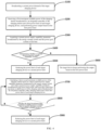
- FIG. 1 is a flowchart of a power control method for a charging station (applied to an integrated controller of the charging station) according to an embodiment of the present disclosure.
- the charging station has an energy storage system and is connected to a power grid system.
- the power control method includes actions at block S 10 to block S40.
- a power supply capability parameter broadcasted by the energy storage system, a power supply capability parameter broadcasted by the power grid system, and a current power demand broadcasted by each target charging device are acquired.
- the target charging device is a charging device having a power output demand in the charging station.
- a first maximum available power of the charging station is calculated based on the power supply capability parameter of the energy storage system and the power supply capability parameter of the power grid system.
- the first maximum available power is calculated by a formula (1).
- APmax GPmax + EPmax ⁇ RP
- APmax represents the first maximum available power
- GPmax represents a maximum available power of the power grid system
- EPmax represents a maximum available power of the energy storage system
- RP represents a predetermined reserved power.
- the first maximum available power is calculated by a formula (2).
- APmax Pc ⁇ GPmax + EPmax where APmax represents the first maximum available power, GPmax represents a maximum available power of the power grid system, EPmax represents a maximum available power of the energy storage system, and Pc represents a power coefficient, where 0 ⁇ Pc ⁇ 1.
- the first maximum available power may also be comprehensively evaluated and calculated in combination with electric energy costs of the energy storage system and the power grid system and an acceptable operation cost of the station according to economy.
- a first power limit of each target charging device is determined based on the first maximum available power of the charging station, the current power demand broadcasted by each target charging device, and a predetermined allocation rule.
- the first maximum available power of the charging station and the first power limit of each target charging device is broadcasted to each target charging device.
- each target charging device may perform power output based on the first power limit.
- Each target charging device may determine whether a sudden drop in a power supply capability occurs based on the received first maximum available power of the charging station, a currently acquired power supply capability parameter broadcasted by the energy storage system, and a currently acquired power supply capability parameter broadcasted by the power grid system.
- Each target charging device may reduce a power limit of the target charging device to a second power limit when the sudden drop in the power supply capability occurs.
- the second power limit may be calculated according to a predetermined algorithm.
- the second power limit is equal to a difference between the first maximum available power and the second maximum available power.
- other algorithms may also be used, which is not limited herein, i.e., active derating is performed to avoid power grid overload of the charging station.
- each target charging device may calculate a second maximum available power of the charging station based on the currently acquired power supply capability parameter broadcasted by the energy storage system and the currently acquired power supply capability parameter broadcasted by the power grid system, and determine that the sudden drop in the power supply capability occurs when the second maximum available power is smaller than the first maximum available power.
- a calculation mode of the second maximum available power is the same as a calculation mode of the first maximum available power.
- the first maximum available power is calculated by the integrated controller of the charging station. Then, each target charging device determines whether the sudden drop in the power supply capability occurs based on the received first maximum available power, and a power supply capability parameter broadcasted by the energy storage system and a power supply capability parameter broadcasted by the power grid system which are currently acquired by the target charging device. Once it is determined that the sudden drop in the power supply capability occurs, the power limit of the target charging device is decreased to the second power limit, to ensure that electric powers of all the current target charging devices do not exceed the power supply capability of the charging station, so as to protect a power grid from overloaded operating conditions.
- a broadcast of the power grid system and a broadcast of each target charging device are periodically performed.
- blocks S10 to S40 are also periodically performed.
- FIG. 2 is a flowchart of a power control method for a charging station (applied to an integrated controller of the charging station) according to another embodiment of the present disclosure. As illustrated in FIG. 2 , in another embodiment, after the actions at block S40, the power control method further includes actions at block S50 to block S60.
- the first power limit of each target charging device is re-determined based on a currently calculated first maximum available power of the charging station, the current power demand broadcasted by each target charging device, and the predetermined allocation rule.
- the currently calculated first maximum available power of the charging station refers to a first maximum available power of the charging station calculated by the integrated controller in a new cycle after the active derating is performed on the target charging device.
- the currently calculated first maximum available power and the re-determined first power limit of each target charging device are broadcasted to each target charging device, so that each target charging device determines whether the first power limit is recalculated based on the received first maximum available power of the charging station, the currently acquired power supply capability parameter broadcasted by the energy storage system, and the currently acquired power supply capability parameter broadcasted by the power grid system, and cancels reduction of the power limit of each target charging device and performs the power output based on the first power limit when the first power limit has been recalculated.
- a latest second maximum available power of the charging station is calculated based on a latest acquired power supply capability parameter broadcasted by the energy storage system and a latest acquired power supply capability parameter broadcasted by the power grid system.
- a latest first maximum available power of the charging station broadcasted by the integrated controller of the charging station and a latest first power limit of each target charging device are received.
- the power output is performed based on the latest received first power limit corresponding to each target charging device when the latest broadcasted first maximum available power is smaller than or equal to the latest second maximum available power.
- the actions at block S30 include actions at block S31 to block S34.
- a maximum request power is calculated based on a current required power broadcasted by each target charging device.
- the maximum request power is equal to a sum of the current required powers broadcasted by the target charging devices.
- the current required power of each target charging device is determined as the first power limit.
- the first power limit is determined based on a power priority level of each target charging device and the current required power, to ensure that the first maximum available power is greater than or equal to a sum of first power limits of the target charging devices.
- the target charging device with a high power priority level may be first satisfied.
- the first maximum available power may also be evenly distributed among the target charging devices; or some first maximum available powers are evenly allocated to some target charging devices, and the rest of first maximum available powers are allocated to the other of the target charging devices based on the power priority level.
- FIG. 3 is a flowchart of a power control method for a charging station (applied in each target charging device of the charging station) according to an embodiment of the present disclosure.
- the target charging device is the charging device having the power output demand in the charging station.
- the charging station has the energy storage system and is connected to the power grid system.
- the power control method includes actions at block S100 to S500.
- a first maximum available power of the charging station broadcasted by an integrated controller of the charging station and a first power limit of each target charging device are received, and power output is performed based on the first power limit.
- the first maximum available power of the charging station and the first power limit of each target charging device are calculated and determined by the integrated controller based on an acquired power supply capability parameter broadcasted by the energy storage system, an acquired power supply capability parameter broadcasted by the power grid system, the current power demand broadcasted by each target charging device, and a predetermined allocation rule.
- the calculation and determination method for the first maximum available power of the charging station and the calculation and determination method for the first power limit of each target charging device are described above, which is not described in detail herein.
- a current power supply capability parameter broadcasted by the energy storage system and a current power supply capability parameter broadcasted by the power grid system are acquired in real time.
- the power limit of each target charging device is reduced to a second power limit, to avoid power grid overload of the charging station.
- block S600 when it is determined that no sudden drop in the power supply capability occurs in block S400, block S600 is entered. In block S600, the target charging device remains output based on the first power limit. It should be noted that blocks S100 to S500 are performed periodically. In addition, the order of block S300 and block S200 may be interchanged.
- the first maximum available power is calculated by the integrated controller of the charging station. Then, each target charging device determines whether the sudden drop in the power supply capability occurs based on the received first maximum available power, and a power supply capability parameter broadcasted by the energy storage system and a power supply capability parameter broadcasted by the power grid system which are currently acquired by the target charging device. Once it is determined that the sudden drop in the power supply capability occurs, the power limit of the target charging device is reduced to the second power limit, to ensure that the electric powers of all the current target charging devices do not exceed the power supply capability of the charging station, so as to protect the power grid from the overloaded operating conditions.
- the actions at block S400 include: calculating a second maximum available power of the charging station based on the currently acquired power supply capability parameter broadcasted by the energy storage system and the currently acquired power supply capability parameter broadcasted by the power grid system; and determining that the sudden drop in the power supply capability occurs when the second maximum available power is smaller than the first maximum available power.
- the second maximum available power is calculated by a formula (3).
- SPmax GPmax + EPmax ⁇ RP
- SPmax represents the second maximum available power of the charging station
- GPmax represents a maximum available power of the power grid system
- EPmax represents a maximum available power of the energy storage system
- RP represents a predetermined reserved power.
- the second maximum available power is calculated by a formula (4).
- SPmax Pc ⁇ GPmax + EPmax
- SPmax represents the second maximum available power of the charging station
- GPmax represents a maximum available power of the power grid system
- EPmax represents a maximum available power of the energy storage system
- Pc represents a power coefficient, where 0 ⁇ Pc ⁇ 1.
- the second power limit is equal to a difference between the first maximum available power and the second maximum available power.
- the second power limit may be calculated by using other algorithms, such as a value subtracted from the difference between the first maximum available power and the second maximum available power.
- a predetermined target charging device determines that the sudden drop in the power supply capability occurs, the power of the target charging device is immediately controlled for derating. Therefore, an effect of actively and timely response may be achieved.
- the overload operating condition of the power grid is avoided. This method is simple in calculation and high in response speed, and may better protect the power grid.
- FIG. 4 is a flowchart of a power control method for a charging station (applied in each target charging device of the charging station) according to another embodiment of the present disclosure. As illustrated in FIG. 4 , in another embodiment, after the actions at block S500, the method further includes actions at block S700 to block 900.
- a latest second maximum available power of the charging station is calculated based on a latest acquired power supply capability parameter broadcasted by the energy storage system and a latest acquired power supply capability parameter broadcasted by the power grid system, and a latest first maximum available power of the charging station broadcasted by the integrated controller of the charging station and a latest first power limit of each target charging device are received.
- the power output is performed based on the latest received first power limit corresponding to each target charging device.
- the power control method for the charging station applied to the integrated controller and the power control method for the charging station applied in each target charging device are introduced above, respectively.
- the power control method for the charging station in the present disclosure is described in more detail through one exemplary embodiment in combination with the integrated controller of the charging station and the target charging device.
- FIG. 5 is a flowchart of a power control method for a charging station combining an integrated controller and a target charging device according to an embodiment of the present disclosure.
- the charging station has the energy storage system, and is provided with the integrated controller and the plurality of target charging devices.
- the target charging device is the charging device having the power output demand in the charging station.
- the charging station is connected to the power grid system.
- the power control method in this embodiment includes actions at blocks S302 to S318.
- the target charging device calculates and broadcasts a power demand of target charging device.
- the integrated controller acquires the power supply capability parameter broadcasted by the energy storage system, the power supply capability parameter broadcasted by the power grid system, and the current power demand broadcasted by each target charging device.
- the power supply capability parameter broadcasted by the energy storage system and the power supply capability parameter broadcasted by the power grid system are calculated and broadcasted by the energy storage system and the power grid system, respectively.
- the integrated controller calculates the first maximum available power of the charging station based on the power supply capability parameter of the energy storage system and the power supply capability parameter of the power grid system.
- the integrated controller determines the first power limit of each target charging device based on the first maximum available power of the charging station, the current power demand broadcasted by each target charging device, and the predetermined allocation rule, and determines a limit output power of the energy storage system.
- the integrated controller broadcasts the first maximum available power of the charging station and the first power limit of each target charging device to each target charging device (i.e., power quota of each target charging device).
- the integrated controller also broadcasts the limit output power of the energy storage system (i.e., a discharge capability requirement of the energy storage system), so that the energy storage system performs power output according to the calculated limit output power of the energy storage system.
- the energy storage system may also continuously broadcast a current output state and an output capability of the energy storage system, to enable the integrated controller and each target charging device to perform corresponding calculations.
- the target charging device receives the first maximum available power of the charging station broadcasted by the integrated controller of the charging station and the first power limit of each target charging device, and performs the power output based on the first power limit.
- Each target charging device may also continuously broadcast current power consumption and power demand thereof.
- the integrated controller continuously calculates and broadcasts the first maximum available power of the charging station, the first power limit of each target charging device, and the limit output power of the energy storage system.
- the target charging device determines whether the sudden drop in the power supply capability occurs based on the first maximum available power of the charging station, the currently acquired power supply capability parameter broadcasted by the energy storage system, and the currently acquired power supply capability parameter broadcasted by the power grid system.
- the target charging device reduces the power limit of each target charging device to the second power limit (i.e., performs active derating) when the sudden drop in the power supply capability occurs.
- the target charging device calculates the second maximum available power of the charging station based on the currently acquired power supply capability parameter broadcasted by the energy storage system and the currently acquired power supply capability parameter broadcasted by the power grid system. The target charging device determines that the sudden drop in the power supply capability occurs when the second maximum available power is smaller than the first maximum available power.
- the target charging device determines that the integrated controller re-completes a quota calculation based on the power supply capability, the target charging device cancels the active derating, and performs power output based on the latest received first power limit value corresponding to the target charging device.
- each target charging device calculates the latest second maximum available power of the charging station based on the latest acquired power supply capability parameter broadcasted by the energy storage system and the latest acquired power supply capability parameter broadcasted by the power grid system.
- Each target charging device receives the latest first maximum available power of the charging station broadcasted by the integrated controller of the charging station and the latest first power limit of each target charging device.
- Each target charging device performs the power output based on the latest received first power limit corresponding to each target charging device when the latest broadcasted first maximum available power is smaller than or equal to the latest second maximum available power, i.e., when the latest broadcasted first maximum available power is smaller than or equal to the latest second maximum available power.
- the integrated controller re-completed the quota calculation based on the power supply capability, and the latest second maximum available power is calculated according to the latest acquired power supply capability parameters broadcasted by the energy storage system and the latest acquired power supply capability parameters broadcasted by the power grid system.
- the electric powers of all target charging devices are ensured not to exceed the power supply capability of the charging station by operating an integrated power distribution scheduling algorithm on the integrated controller in combination with a distributed control algorithm operating on the target charging device side, to protect the power grid from the overloaded operating.
- the present disclosure further provides a power control apparatus of a charging station, applied in an integrated controller of the charging station.
- the power control apparatus includes a memory and a processor.
- the memory has a control program stored therein.
- the control program is configured to, when executed by the processor, implement the power control method applied in the integrated controller according to any one of the above embodiments.
- the processor may be a central processing unit (CPU), a digital processing unit, or the like.
- the processor sends and receives data through a communication interface.
- the memory is configured to store a program executed by the processor.
- the memory is any medium that may be used to carry or store desired program code in the form of instructions or data structures and may be accessed by a computer, or a combination of a plurality of memories.
- a computing program may be downloaded from a computer-readable storage medium to a respective computing/processing device or to a computer or external storage device via a network (e.g., the Internet, a local area network, a wide area network, and/or a wireless network).
- a network e.g., the Internet, a local area network, a wide area network, and/or a wireless network.
- the present disclosure further provides a power control apparatus of a charging station, applied in each target charging device of the charging station.
- the power control apparatus includes a memory and a processor.
- the memory has a control program stored therein.
- the control program is configured to, when executed by the processor, implement the power control method applied in the target charging device according to any one of the above embodiments.
- the processor may be a central processing unit (CPU), a digital processing unit, or the like.
- the processor sends and receives data through a communication interface.
- the memory is configured to store a program executed by the processor.
- the memory is any medium that may be used to carry or store desired program code in the form of instructions or data structures and may be accessed by a computer, or a combination of a plurality of memories.
- the computing program may be downloaded from a computer-readable storage medium to a respective computing/processing device or to a computer or external storage device via a network (e.g., the Internet, a local area network, a wide area network, and/or a wireless network).
- a network e.g., the Internet, a local area network, a wide area network, and/or a wireless network.
- the present disclosure further provides a power control system of a charging station, including the power control apparatus of the charging station applied in the integrated controller of the charging station and the power control apparatus of the charging station applied in each target charging device of the charging station.
Landscapes
- Engineering & Computer Science (AREA)
- Power Engineering (AREA)
- Transportation (AREA)
- Mechanical Engineering (AREA)
- Charge And Discharge Circuits For Batteries Or The Like (AREA)
- Supply And Distribution Of Alternating Current (AREA)
Abstract
Description
- The present disclosure relates to the field of charging station control, and in particular, to a power control method for a charging station and a power control apparatus and system of a charging station.
- Currently, with the popularization of electric vehicles, there is a growing number of charging stations. During construction of these charging stations, a charging station having an energy storage unit is gradually derived for the purposes of avoiding excessive impact on a power grid, achieving cooperative use of various electric energy sources, and the like.
- In the related art, research has been conducted on a control method of an energy storage system. For example, a power supply plan for the power grid and the energy storage system is decided by designing a scheduling algorithm, which focuses on solving a problem of cooperative scheduling among different electric energy.
- However, in diverse current studies, it is not considered that in some scheduling scenarios, the power grid or the energy storage system causes a sudden drop in an output capability due to a predetermined reason, such as a fault, and a load (i.e., a charger) may not perform power derating in time, resulting in a risk of power grid overload. For the charging station, considering both economic factors and a current state of a regional power grid, a power supply capability of the power grid often may not satisfy the requirements for full power output of all the charging devices simultaneously. In such cases, compared with reasonably scheduling different energy sources, it is more important to ensure that the power grid overload is avoided when the charging device operates.
- In view of the above problems, the present disclosure is proposed to overcome the above problems or at least partially solve the above problems. To this end, the present disclosure provides a power control method for a charging station, a power control apparatus and system of a charging station.
- An embodiment of a first aspect of the present disclosure is to provide a power control method for a charging station, applied to an integrated controller of the charging station, which may effectively avoid power grid overload.
- Another embodiment of the present disclosure is to improve a response speed of power grid overload protection, to better prevent the power grid overload.
- An embodiment of a second aspect of the present disclosure is to provide a power control method for a charging station, applied in each target charging device of the charging station, which may effectively avoid the power grid overload.
- An embodiment of a third aspect of the present disclosure is to provide a power control apparatus of a charging station, applied in an integrated controller of the charging station, which may efficaciously protect the power grid.
- An embodiment of a fourth aspect of the present disclosure is to provide a power control apparatus of a charging station, applied in each target charging device of the charging station, which may effectually protect the power grid.
- An embodiment of a fifth aspect of the present disclosure is to provide a power control system of a charging station, including the power control apparatus applied in each target charging device of the charging station and the power control apparatus applied in the integrated controller of the charging station, which may availably protect the power grid.
- In particular, according to a first aspect of embodiments of the present disclosure, provided is a power control method for a charging station, applied to an integrated controller of the charging station, where the charging station has an energy storage system and is connected to a power grid system, the power control method including: acquiring a power supply capability parameter broadcasted by the energy storage system, a power supply capability parameter broadcasted by the power grid system, and a current power demand broadcasted by each target charging device, the target charging device is a charging device having a power output demand in the charging station; calculating a first maximum available power of the charging station based on the power supply capability parameter of the energy storage system and the power supply capability parameter of the power grid system; determining a first power limit of each target charging device based on the first maximum available power of the charging station, the current power demand broadcasted by each target charging device, and a predetermined allocation rule; and broadcasting the first maximum available power of the charging station and the first power limit of each target charging device to each target charging device, so that each target charging device performs power output based on the first power limit, determines whether a sudden drop in a power supply capability occurs based on the received first maximum available power of the charging station, a currently acquired power supply capability parameter broadcasted by the energy storage system, and a currently acquired power supply capability parameter broadcasted by the power grid system, and reduces a power limit of the target charging device to a second power limit when the sudden drop in the power supply capability occurs, to avoid power grid overload of the charging station.
- Exemplarily, the power control method further includes, subsequent to broadcasting the first maximum available power of the charging station and the first power limit of each target charging device to each target charging device: re-determining the first power limit of each target charging device based on a currently calculated first maximum available power of the charging station, the current power demand broadcasted by each target charging device, and the predetermined allocation rule; and broadcasting the currently calculated first maximum available power and the re-determined first power limit of each target charging device to each target charging device, so that each target charging device determines whether the first power limit is recalculated based on the received first maximum available power of the charging station, the currently acquired power supply capability parameter broadcasted by the energy storage system, and the currently acquired power supply capability parameter broadcasted by the power grid system, and cancels reduction of the power limit of the each target charging device and performs the power output based on the first power limit when the first power limit has been recalculated.
- Exemplarily, the determining the first power limit of each target charging device based on the first maximum available power of the charging station, the current power demand broadcasted by each target charging device, and the predetermined allocation rule includes: calculating a maximum request power based on a current required power broadcasted by each target charging device; and determining the current required power of each target charging device as the first power limit when the first maximum available power is greater than or equal to the maximum request power.
- Exemplarily, the power control method further includes, subsequent to the calculating the maximum request power based on the current demand power broadcasted by each target charging device: determining the first power limit based on a power priority level of each target charging device and the current required power when the first maximum available power is smaller than the maximum request power, to ensure that the first maximum available power is greater than or equal to a sum of first power limits of the target charging devices.
- Exemplarily, the first maximum available power is calculated as APmax=GPmax+EPmax-RP, where APmax represents the first maximum available power, GPmax represents a maximum available power of the power grid system, EPmax represents a maximum available power of the energy storage system, and RP represents a predetermined reserved power.
- Exemplarily, the first maximum available power is calculated as APmax=Pc*(GPmax+EPmax), where APmax represents the first maximum available power, GPmax represents a maximum available power of the power grid system, EPmax represents a maximum available power of the energy storage system, and Pc represents a power coefficient, where 0<Pc≤1.
- In particular, according to a second aspect of the embodiments of the present disclosure, further provided is a power control method for a charging station, applied in each target charging device of the charging station, where the target charging device is a charging device having a power output demand in the charging station, the charging station has an energy storage system and is connected to a power grid system, the power control method including: broadcasting a current power demand of each target charging device; receiving a first maximum available power of the charging station broadcasted by an integrated controller of the charging station and a first power limit of each target charging device, and performing power output based on the first power limit, the first maximum available power of the charging station and the first power limit of each target charging device are calculated and determined by the integrated controller based on an acquired power supply capability parameter broadcasted by the energy storage system, an acquired power supply capability parameter broadcasted by the power grid system, the current power demand broadcasted by each target charging device, and a predetermined allocation rule; acquiring a current power supply capability parameter broadcasted by the energy storage system and a current power supply capability parameter broadcasted by the power grid system in real time, and determining whether a sudden drop in a power supply capability occurs based on the first maximum available power of the charging station and the currently acquired power supply capability parameter broadcasted by the energy storage system and the currently acquired power supply capability parameter broadcasted by the power grid system; and reducing the power limit of each target charging device to a second power limit when the sudden drop in the power supply capability occurs, to avoid power grid overload of the charging station.
- Exemplarily, the determining whether the sudden drop in the power supply capability occurs based on the first maximum available power of the charging station, the currently acquired power supply capability parameter broadcasted by the energy storage system, and the currently acquired power supply capability parameter broadcasted by the power grid system includes: calculating a second maximum available power of the charging station based on the currently acquired power supply capability parameter broadcasted by the energy storage system and the currently acquired power supply capability parameter broadcasted by the power grid system; and determining that the sudden drop in the power supply capability occurs when the second maximum available power is smaller than the first maximum available power.
- Exemplarily, the power control method further includes, subsequent to reducing the power limit of each target charging device to the second power limit: calculating a latest second maximum available power of the charging station based on a latest acquired power supply capability parameter broadcasted by the energy storage system and a latest acquired power supply capability parameter broadcasted by the power grid system, and receiving a latest first maximum available power of the charging station broadcasted by the integrated controller of the charging station and a latest first power limit of each target charging device; and performing the power output based on the latest received first power limit corresponding to each target charging device when the latest broadcasted first maximum available power is smaller than or equal to the latest second maximum available power.
- Exemplarily, the second maximum available power is calculated as SPmax=GPmax+EPmax-RP, where SPmax represents the second maximum available power of the charging station, GPmax represents a maximum available power of the power grid system, EPmax represents a maximum available power of the energy storage system, and RP represents a predetermined reserved power.
- Exemplarily, the second maximum available power is calculated as SPmax=Pc*(GPmax+EPmax), where SPmax represents the second maximum available power of the charging station, GPmax represents a maximum available power of the power grid system, EPmax represents a maximum available power of the energy storage system, and Pc represents a power coefficient, where 0<Pc≤1.
- Exemplarily, the second power limit is equal to a difference between the first maximum available power and the second maximum available power.
- In particular, according to a third aspect of the embodiments of the present disclosure, provided is a power control apparatus of a charging station, applied in an integrated controller of the charging station. The power control apparatus includes: a memory having a control program stored therein; and a processor. The control program is configured to, when executed by the processor, implement the power control method applied to the integrated controller of the charging station according to any one of the above embodiments.
- In particular, according to a fourth aspect of the embodiments of the present disclosure, provided is a power control apparatus of a charging station, applied in each target charging device of the charging station. The power control apparatus includes: a memory having a control program stored therein; and a processor. The control program is configured to, when executed by the processor, implement the power control method applied in each target charging device of the charging station according to any one of the above embodiments.
- In particular, according to a fifth aspect of the embodiments of the present disclosure, provided is a power control system of a charging station, including the power control apparatus applied in each target charging device of the charging station and the power control apparatus applied in the integrated controller of the charging station.
- In the present disclosure, the first maximum available power is calculated by means of the integrated controller of the charging station. Then, each target charging device determines whether the sudden drop in the power supply capability occurs based on the received first maximum available power, and the power supply capability parameter broadcasted by the energy storage system and the power supply capability parameter broadcasted by the power grid system which are currently acquired by the target charging device. Once it is determined that the sudden drop in the power supply capability occurs, the power limit of the target charging device is reduced to the second power limit, to ensure that electric powers of all the current target charging devices do not exceed the power supply capability of the charging station, so as to protect the power grid from existing overload operating conditions.
- Further, in the present disclosure, when a predetermined target charging device determines that the sudden drop in the power supply capability occurs, the target charging device immediately controls a power of the predetermined target charging device to perform derating, which may achieve an effect of proactive and timely response and prevents the power grid from having the overload operating condition. This method is simple to calculate, with a fast response speed, and may better protect the power grid.
- The above description is merely an overview of the technical solutions of the present disclosure. In order to more clearly understand the technical means of the present disclosure, the technical solutions to implement them based on the disclosure of the description and to clarify and explain the above and other embodiments, features, and advantages of the present disclosure, exemplary implementations of the present disclosure will be further described in detail.
- The exemplary embodiments of the present disclosure will be described in detail below in conjunction with the accompanying drawings, and the above and other embodiments, advantages, and features of the present disclosure would become more apparent to those skilled in the art.
- Some exemplary embodiments of the present disclosure will hereinafter be described in detail with reference to the accompanying drawings that are exemplary merely, rather than limiting the present disclosure. In the accompanying drawings, same or similar components or parts are denoted by same reference numerals. It should be understood by those skilled in the art that these accompanying drawings are not necessarily drawn to scale, in which:
-
FIG. 1 is a flowchart of a power control method for a charging station (applied to an integrated controller of the charging station) according to an embodiment of the present disclosure. -
FIG. 2 is a flowchart of a power control method for a charging station (applied to an integrated controller of the charging station) according to another embodiment of the present disclosure. -
FIG. 3 is a flowchart of a power control method for a charging station (applied in a target charging device of the charging station) according to an embodiment of the present disclosure. -
FIG. 4 is a flowchart of a power control method for a charging station (applied in a target charging device of the charging station) according to another embodiment of the present disclosure. -
FIG. 5 is a flowchart of a power control method for a charging station combining an integrated controller and a target charging device according to an embodiment of the present disclosure. - Some embodiments of the present disclosure will be described in detail below with reference to the accompanying drawings. Although some embodiments of the present disclosure are illustrated in the drawings, it should be understood that the present disclosure may be embodied in various forms and should not be construed as limited to the embodiments set forth herein. Instead, these embodiments are provided for a complete and thorough understanding of the present disclosure, and these embodiments can fully convey the scope of the present disclosure to those skilled in the art.
- The present disclosure provides a power control method for a charging station, applied to an integrated controller of the charging station.
FIG. 1 is a flowchart of a power control method for a charging station (applied to an integrated controller of the charging station) according to an embodiment of the present disclosure. In this embodiment, the charging station has an energy storage system and is connected to a power grid system. As illustrated inFIG. 1 , the power control method includes actions atblock S 10 to block S40. - At
block S 10, a power supply capability parameter broadcasted by the energy storage system, a power supply capability parameter broadcasted by the power grid system, and a current power demand broadcasted by each target charging device are acquired. The target charging device is a charging device having a power output demand in the charging station. - At block S20, a first maximum available power of the charging station is calculated based on the power supply capability parameter of the energy storage system and the power supply capability parameter of the power grid system.
- In an implementation, the first maximum available power is calculated by a formula (1).

- In another implementation, the first maximum available power is calculated by a formula (2).

- In other embodiments, the first maximum available power may also be comprehensively evaluated and calculated in combination with electric energy costs of the energy storage system and the power grid system and an acceptable operation cost of the station according to economy.
- At block S30, a first power limit of each target charging device is determined based on the first maximum available power of the charging station, the current power demand broadcasted by each target charging device, and a predetermined allocation rule.
- At block S40, the first maximum available power of the charging station and the first power limit of each target charging device is broadcasted to each target charging device. In this way, when receiving the broadcasted first maximum available power and the first power limit of each target charging device, each target charging device may perform power output based on the first power limit. Each target charging device may determine whether a sudden drop in a power supply capability occurs based on the received first maximum available power of the charging station, a currently acquired power supply capability parameter broadcasted by the energy storage system, and a currently acquired power supply capability parameter broadcasted by the power grid system. Each target charging device may reduce a power limit of the target charging device to a second power limit when the sudden drop in the power supply capability occurs. The second power limit may be calculated according to a predetermined algorithm. For example, the second power limit is equal to a difference between the first maximum available power and the second maximum available power. Moreover, other algorithms may also be used, which is not limited herein, i.e., active derating is performed to avoid power grid overload of the charging station.
- Exemplarily, each target charging device may calculate a second maximum available power of the charging station based on the currently acquired power supply capability parameter broadcasted by the energy storage system and the currently acquired power supply capability parameter broadcasted by the power grid system, and determine that the sudden drop in the power supply capability occurs when the second maximum available power is smaller than the first maximum available power. Exemplarily, a calculation mode of the second maximum available power is the same as a calculation mode of the first maximum available power.
- In this embodiment, the first maximum available power is calculated by the integrated controller of the charging station. Then, each target charging device determines whether the sudden drop in the power supply capability occurs based on the received first maximum available power, and a power supply capability parameter broadcasted by the energy storage system and a power supply capability parameter broadcasted by the power grid system which are currently acquired by the target charging device. Once it is determined that the sudden drop in the power supply capability occurs, the power limit of the target charging device is decreased to the second power limit, to ensure that electric powers of all the current target charging devices do not exceed the power supply capability of the charging station, so as to protect a power grid from overloaded operating conditions.
- It should be noted that a broadcast of the power grid system and a broadcast of each target charging device are periodically performed. Correspondingly, blocks S10 to S40 are also periodically performed.
-
FIG. 2 is a flowchart of a power control method for a charging station (applied to an integrated controller of the charging station) according to another embodiment of the present disclosure. As illustrated inFIG. 2 , in another embodiment, after the actions at block S40, the power control method further includes actions at block S50 to block S60. - At block S50, the first power limit of each target charging device is re-determined based on a currently calculated first maximum available power of the charging station, the current power demand broadcasted by each target charging device, and the predetermined allocation rule.
- In this block, the currently calculated first maximum available power of the charging station refers to a first maximum available power of the charging station calculated by the integrated controller in a new cycle after the active derating is performed on the target charging device.
- At block S60, the currently calculated first maximum available power and the re-determined first power limit of each target charging device are broadcasted to each target charging device, so that each target charging device determines whether the first power limit is recalculated based on the received first maximum available power of the charging station, the currently acquired power supply capability parameter broadcasted by the energy storage system, and the currently acquired power supply capability parameter broadcasted by the power grid system, and cancels reduction of the power limit of each target charging device and performs the power output based on the first power limit when the first power limit has been recalculated.
- Exemplarily, a latest second maximum available power of the charging station is calculated based on a latest acquired power supply capability parameter broadcasted by the energy storage system and a latest acquired power supply capability parameter broadcasted by the power grid system. A latest first maximum available power of the charging station broadcasted by the integrated controller of the charging station and a latest first power limit of each target charging device are received. The power output is performed based on the latest received first power limit corresponding to each target charging device when the latest broadcasted first maximum available power is smaller than or equal to the latest second maximum available power.
- In an embodiment, as illustrated in
FIG. 2 , the actions at block S30 include actions at block S31 to block S34. - At block S31, a maximum request power is calculated based on a current required power broadcasted by each target charging device. Exemplarily, the maximum request power is equal to a sum of the current required powers broadcasted by the target charging devices.
- At block S32, it is determined that whether the first maximum available power is greater than or equal to the maximum request power; and when the first maximum available power is greater than or equal to the maximum request power, entering block S33, when the first maximum available power is smaller than the maximum request power, entering block S34.
- At block S33, the current required power of each target charging device is determined as the first power limit.
- At block S34, the first power limit is determined based on a power priority level of each target charging device and the current required power, to ensure that the first maximum available power is greater than or equal to a sum of first power limits of the target charging devices. In some embodiments, the target charging device with a high power priority level may be first satisfied. In other embodiments, the first maximum available power may also be evenly distributed among the target charging devices; or some first maximum available powers are evenly allocated to some target charging devices, and the rest of first maximum available powers are allocated to the other of the target charging devices based on the power priority level.
- Correspondingly, the present disclosure further provides a power control method for a charging station, applied in each target charging device of the charging station.
FIG. 3 is a flowchart of a power control method for a charging station (applied in each target charging device of the charging station) according to an embodiment of the present disclosure. In this embodiment, the target charging device is the charging device having the power output demand in the charging station. The charging station has the energy storage system and is connected to the power grid system. In an embodiment, as illustrated inFIG. 3 , the power control method includes actions at block S100 to S500. - At
block S 100, a current power demand of the target charging device is broadcasted. - At block S200, a first maximum available power of the charging station broadcasted by an integrated controller of the charging station and a first power limit of each target charging device are received, and power output is performed based on the first power limit. The first maximum available power of the charging station and the first power limit of each target charging device are calculated and determined by the integrated controller based on an acquired power supply capability parameter broadcasted by the energy storage system, an acquired power supply capability parameter broadcasted by the power grid system, the current power demand broadcasted by each target charging device, and a predetermined allocation rule. The calculation and determination method for the first maximum available power of the charging station and the calculation and determination method for the first power limit of each target charging device are described above, which is not described in detail herein.
- At block S300, a current power supply capability parameter broadcasted by the energy storage system and a current power supply capability parameter broadcasted by the power grid system are acquired in real time.
- At block S400, it is determined that whether a sudden drop in a power supply capability occurs based on the first maximum available power of the charging station, the currently acquired power supply capability parameter broadcasted by the energy storage system, and the currently acquired power supply capability parameter broadcasted by the power grid system. When the sudden drop in the power supply capability occurs, entering the block S500.
- At block S500, the power limit of each target charging device is reduced to a second power limit, to avoid power grid overload of the charging station.
- In some embodiments, when it is determined that no sudden drop in the power supply capability occurs in block S400, block S600 is entered. In block S600, the target charging device remains output based on the first power limit. It should be noted that blocks S100 to S500 are performed periodically. In addition, the order of block S300 and block S200 may be interchanged.
- In this embodiment, the first maximum available power is calculated by the integrated controller of the charging station. Then, each target charging device determines whether the sudden drop in the power supply capability occurs based on the received first maximum available power, and a power supply capability parameter broadcasted by the energy storage system and a power supply capability parameter broadcasted by the power grid system which are currently acquired by the target charging device. Once it is determined that the sudden drop in the power supply capability occurs, the power limit of the target charging device is reduced to the second power limit, to ensure that the electric powers of all the current target charging devices do not exceed the power supply capability of the charging station, so as to protect the power grid from the overloaded operating conditions.
- In an embodiment, the actions at block S400 include: calculating a second maximum available power of the charging station based on the currently acquired power supply capability parameter broadcasted by the energy storage system and the currently acquired power supply capability parameter broadcasted by the power grid system; and determining that the sudden drop in the power supply capability occurs when the second maximum available power is smaller than the first maximum available power.
- In an implementation, the second maximum available power is calculated by a formula (3).

- In another implementation, the second maximum available power is calculated by a formula (4).

- Exemplarily, the second power limit is equal to a difference between the first maximum available power and the second maximum available power. In other embodiments, the second power limit may be calculated by using other algorithms, such as a value subtracted from the difference between the first maximum available power and the second maximum available power. In practical application, there is generally no case where a plurality of target charging devices simultaneously has the second maximum available power smaller than the first maximum available power. When a predetermined target charging device determines that the sudden drop in the power supply capability occurs, the power of the target charging device is immediately controlled for derating. Therefore, an effect of actively and timely response may be achieved. Moreover, the overload operating condition of the power grid is avoided. This method is simple in calculation and high in response speed, and may better protect the power grid.
-
FIG. 4 is a flowchart of a power control method for a charging station (applied in each target charging device of the charging station) according to another embodiment of the present disclosure. As illustrated inFIG. 4 , in another embodiment, after the actions at block S500, the method further includes actions at block S700 to block 900. - At block S700, a latest second maximum available power of the charging station is calculated based on a latest acquired power supply capability parameter broadcasted by the energy storage system and a latest acquired power supply capability parameter broadcasted by the power grid system, and a latest first maximum available power of the charging station broadcasted by the integrated controller of the charging station and a latest first power limit of each target charging device are received.
- At block S800, it is determined that whether the latest broadcasted first maximum available power is smaller than or equal to the latest second maximum available power; and when the latest broadcasted first maximum available power is smaller than or equal to the latest second maximum available power, entering block S900, when the latest broadcasted first maximum available power is greater than the latest second maximum available power, returning back to block S700.
- At block S900, the power output is performed based on the latest received first power limit corresponding to each target charging device.
- The power control method for the charging station applied to the integrated controller and the power control method for the charging station applied in each target charging device are introduced above, respectively. The power control method for the charging station in the present disclosure is described in more detail through one exemplary embodiment in combination with the integrated controller of the charging station and the target charging device.
-
FIG. 5 is a flowchart of a power control method for a charging station combining an integrated controller and a target charging device according to an embodiment of the present disclosure. In this embodiment, the charging station has the energy storage system, and is provided with the integrated controller and the plurality of target charging devices. The target charging device is the charging device having the power output demand in the charging station. Moreover, the charging station is connected to the power grid system. As illustrated inFIG. 5 , the power control method in this embodiment includes actions at blocks S302 to S318. - At block S302, the target charging device calculates and broadcasts a power demand of target charging device.
- At block S304, the integrated controller acquires the power supply capability parameter broadcasted by the energy storage system, the power supply capability parameter broadcasted by the power grid system, and the current power demand broadcasted by each target charging device. The power supply capability parameter broadcasted by the energy storage system and the power supply capability parameter broadcasted by the power grid system are calculated and broadcasted by the energy storage system and the power grid system, respectively.
- At block S306, the integrated controller calculates the first maximum available power of the charging station based on the power supply capability parameter of the energy storage system and the power supply capability parameter of the power grid system.
- At block S308, the integrated controller determines the first power limit of each target charging device based on the first maximum available power of the charging station, the current power demand broadcasted by each target charging device, and the predetermined allocation rule, and determines a limit output power of the energy storage system.
- At block S310, the integrated controller broadcasts the first maximum available power of the charging station and the first power limit of each target charging device to each target charging device (i.e., power quota of each target charging device).
- Meanwhile, the integrated controller also broadcasts the limit output power of the energy storage system (i.e., a discharge capability requirement of the energy storage system), so that the energy storage system performs power output according to the calculated limit output power of the energy storage system. The energy storage system may also continuously broadcast a current output state and an output capability of the energy storage system, to enable the integrated controller and each target charging device to perform corresponding calculations.
- At block S312, the target charging device receives the first maximum available power of the charging station broadcasted by the integrated controller of the charging station and the first power limit of each target charging device, and performs the power output based on the first power limit. Each target charging device may also continuously broadcast current power consumption and power demand thereof.
- At block S314, the integrated controller continuously calculates and broadcasts the first maximum available power of the charging station, the first power limit of each target charging device, and the limit output power of the energy storage system.
- At block S316, the target charging device determines whether the sudden drop in the power supply capability occurs based on the first maximum available power of the charging station, the currently acquired power supply capability parameter broadcasted by the energy storage system, and the currently acquired power supply capability parameter broadcasted by the power grid system. The target charging device reduces the power limit of each target charging device to the second power limit (i.e., performs active derating) when the sudden drop in the power supply capability occurs.
- In some embodiments, the target charging device calculates the second maximum available power of the charging station based on the currently acquired power supply capability parameter broadcasted by the energy storage system and the currently acquired power supply capability parameter broadcasted by the power grid system. The target charging device determines that the sudden drop in the power supply capability occurs when the second maximum available power is smaller than the first maximum available power.
- At block S318, after the target charging device determines that the integrated controller re-completes a quota calculation based on the power supply capability, the target charging device cancels the active derating, and performs power output based on the latest received first power limit value corresponding to the target charging device.
- In some embodiments, each target charging device calculates the latest second maximum available power of the charging station based on the latest acquired power supply capability parameter broadcasted by the energy storage system and the latest acquired power supply capability parameter broadcasted by the power grid system. Each target charging device receives the latest first maximum available power of the charging station broadcasted by the integrated controller of the charging station and the latest first power limit of each target charging device. Each target charging device performs the power output based on the latest received first power limit corresponding to each target charging device when the latest broadcasted first maximum available power is smaller than or equal to the latest second maximum available power, i.e., when the latest broadcasted first maximum available power is smaller than or equal to the latest second maximum available power. It is considered that the integrated controller re-completed the quota calculation based on the power supply capability, and the latest second maximum available power is calculated according to the latest acquired power supply capability parameters broadcasted by the energy storage system and the latest acquired power supply capability parameters broadcasted by the power grid system.
- In this embodiment, the electric powers of all target charging devices are ensured not to exceed the power supply capability of the charging station by operating an integrated power distribution scheduling algorithm on the integrated controller in combination with a distributed control algorithm operating on the target charging device side, to protect the power grid from the overloaded operating.
- Based on the same technical concept, the present disclosure further provides a power control apparatus of a charging station, applied in an integrated controller of the charging station. The power control apparatus includes a memory and a processor. The memory has a control program stored therein. The control program is configured to, when executed by the processor, implement the power control method applied in the integrated controller according to any one of the above embodiments. The processor may be a central processing unit (CPU), a digital processing unit, or the like. The processor sends and receives data through a communication interface. The memory is configured to store a program executed by the processor. The memory is any medium that may be used to carry or store desired program code in the form of instructions or data structures and may be accessed by a computer, or a combination of a plurality of memories. A computing program may be downloaded from a computer-readable storage medium to a respective computing/processing device or to a computer or external storage device via a network (e.g., the Internet, a local area network, a wide area network, and/or a wireless network).
- Based on the same technical concept, the present disclosure further provides a power control apparatus of a charging station, applied in each target charging device of the charging station. The power control apparatus includes a memory and a processor. The memory has a control program stored therein. The control program is configured to, when executed by the processor, implement the power control method applied in the target charging device according to any one of the above embodiments. The processor may be a central processing unit (CPU), a digital processing unit, or the like. The processor sends and receives data through a communication interface. The memory is configured to store a program executed by the processor. The memory is any medium that may be used to carry or store desired program code in the form of instructions or data structures and may be accessed by a computer, or a combination of a plurality of memories. The computing program may be downloaded from a computer-readable storage medium to a respective computing/processing device or to a computer or external storage device via a network (e.g., the Internet, a local area network, a wide area network, and/or a wireless network).
- Based on the same technical concept, the present disclosure further provides a power control system of a charging station, including the power control apparatus of the charging station applied in the integrated controller of the charging station and the power control apparatus of the charging station applied in each target charging device of the charging station.
- Although exemplary embodiments of the present disclosure have been illustrated and described in detail herein, it is conceivable for those skilled in the art that various modifications and variations can be directly determined or derived based on the disclosure of the present disclosure without departing from the principles and spirits of the present disclosure. Therefore, the scope of the present disclosure shall be understood and considered to cover all these variations or modifications and other variations or modifications.
Claims (15)
- A power control method for a charging station, applied to an integrated controller of the charging station, wherein the charging station has an energy storage system and is connected to a power grid system, the power control method comprising:acquiring a power supply capability parameter broadcasted by the energy storage system, a power supply capability parameter broadcasted by the power grid system and a current power demand broadcasted by each target charging device, the target charging device being a charging device having a power output demand in the charging station;calculating a first maximum available power of the charging station based on the power supply capability parameter of the energy storage system and the power supply capability parameter of the power grid system;determining a first power limit of each target charging device based on the first maximum available power of the charging station, the current power demand broadcasted by each target charging device, and a predetermined allocation rule; andbroadcasting the first maximum available power of the charging station and the first power limit of each target charging device to each target charging device, so that each target charging device performs power output based on the first power limit, determines whether a sudden drop in a power supply capability occurs based on the received first maximum available power of the charging station, a currently acquired power supply capability parameter broadcasted by the energy storage system, and a currently acquired power supply capability parameter broadcasted by the power grid system, and reduces a power limit of the target charging device to a second power limit when the sudden drop in the power supply capability occurs, to avoid power grid overload of the charging station.
- The power control method according to claim 1, further comprising, subsequent to broadcasting the first maximum available power of the charging station and the first power limit of each target charging device to each target charging device:re-determining the first power limit of each target charging device based on a currently calculated first maximum available power of the charging station, the current power demand broadcasted by each target charging device, and the predetermined allocation rule; andbroadcasting the currently calculated first maximum available power and the re-determined first power limit of each target charging device to each target charging device, so that each target charging device determines whether the first power limit is recalculated based on the received first maximum available power of the charging station and the currently acquired power supply capability parameter broadcasted by the energy storage system and the currently acquired power supply capability parameter broadcasted by the energy storage system the power grid system, and cancels reduction of the power limit of each target charging device and performs the power output based on the first power limit when the first power limit has been recalculated.
- The power control method according to claim 1 or 2, wherein said determining the first power limit of each target charging device based on the first maximum available power of the charging station, the current power demand broadcasted by each target charging device, and the predetermined allocation rule comprises:calculating a maximum request power based on a current required power broadcasted by each target charging device; anddetermining the current required power of each target charging device as the first power limit when the first maximum available power is greater than or equal to the maximum request power.
- The power control method according to claim 3, further comprising, subsequent to said calculating the maximum request power based on the current demand power broadcasted by each target charging device:
determining the first power limit based on a power priority level of each target charging device and the current required power when the first maximum available power is smaller than the maximum request power, to ensure that the first maximum available power is greater than or equal to a sum of first power limits of the target charging devices. - The power control method according to claim 1 or 2, wherein the first maximum available power is calculated as APmax=GPmax+EPmax-RP,
where APmax represents the first maximum available power, GPmax represents a maximum available power of the power grid system, EPmax represents a maximum available power of the energy storage system, and RP represents a predetermined reserved power. - The power control method according to claim 1 or 2, wherein the first maximum available power is calculated as APmax=Pc*(GPmax+EPmax),
where APmax represents the first maximum available power, GPmax represents a maximum available power of the power grid system, EPmax represents a maximum available power of the energy storage system, and Pc represents a power coefficient, where 0<Pc≤1. - A power control method for a charging station, applied in each target charging device of the charging station, wherein the target charging device is a charging device having a power output demand in the charging station, the charging station has an energy storage system and is connected to a power grid system, the power control method comprising:broadcasting a current power demand of each target charging device;receiving a first maximum available power of the charging station broadcasted by an integrated controller of the charging station and a first power limit of each target charging device, and performing power output based on the first power limit, the first maximum available power of the charging station and the first power limit of each target charging device being calculated and determined by the integrated controller based on an acquired power supply capability parameter broadcasted by the energy storage system, an acquired power supply capability parameter broadcasted by the power grid system, the current power demand broadcasted by each target charging device, and a predetermined allocation rule;acquiring a current power supply capability parameter broadcasted by the energy storage system and a current power supply capability parameter broadcasted by the power grid system in real time, and determining whether a sudden drop in a power supply capability occurs based on the first maximum available power of the charging station, the currently acquired power supply capability parameter broadcasted by the energy storage system, and the currently acquired power supply capability parameter broadcasted by the power grid system; andreducing the power limit of each target charging device to a second power limit when the sudden drop in the power supply capability occurs, to avoid power grid overload of the charging station.
- The power control method according to claim 7, wherein said determining whether the sudden drop in the power supply capability occurs based on the first maximum available power of the charging station, the currently acquired power supply capability parameter broadcasted by the energy storage system, and the currently acquired power supply capability parameter broadcasted by the power grid system comprises:calculating a second maximum available power of the charging station based on the currently acquired power supply capability parameter broadcasted by the energy storage system and the currently acquired power supply capability parameter broadcasted by the power grid system; anddetermining that the sudden drop in the power supply capability occurs when the second maximum available power is smaller than the first maximum available power.
- The power control method according to claim 7, wherein further comprising, subsequent to reducing the power limit of each target charging device to the second power limit:calculating a latest second maximum available power of the charging station based on a latest acquired power supply capability parameter broadcasted by the energy storage system and a latest acquired power supply capability parameter broadcasted by the power grid system, and receiving a latest first maximum available power of the charging station broadcasted by the integrated controller of the charging station and a latest first power limit of each target charging device; andperforming the power output based on the latest received first power limit corresponding to each target charging device when the latest broadcasted first maximum available power is smaller than or equal to the latest second maximum available power.
- The power control method according to claim 8 or 9, wherein the second maximum available power is calculated as SPmax=GPmax+EPmax-RP,
where SPmax represents the second maximum available power of the charging station, GPmax represents a maximum available power of the power grid system, EPmax represents a maximum available power of the energy storage system, and RP represents a predetermined reserved power. - The power control method according to claim 8 or 9, wherein the second maximum available power is calculated as SPmax=Pc*(GPmax+EPmax),
where SPmax represents the second maximum available power of the charging station, GPmax represents a maximum available power of the power grid system, EPmax represents a maximum available power of the energy storage system, and Pc represents a power coefficient, where 0<Pc< 1. - The power control method according to claim 8, wherein the second power limit is equal to a difference between the first maximum available power and the second maximum available power.
- A power control apparatus of a charging station, applied in an integrated controller of the charging station, the power control apparatus comprising:a memory having a control program stored therein; anda processor,wherein the control program is configured to, when executed by the processor, implement the power control method according to any one of claims 1 to 6.
- A power control apparatus of a charging station, applied in each target charging device of the charging station, the power control apparatus comprising:a memory having a control program stored therein; anda processor,wherein the control program is configured to, when executed by the processor, implement the power control method according to any one of claims 7 to 12.
- A power control system of a charging station, the power control system comprising the power control apparatus according to claim 13 and the power control apparatus according to claim 14.
Applications Claiming Priority (1)
| Application Number | Priority Date | Filing Date | Title |
|---|---|---|---|
| PCT/CN2021/090869 WO2022226866A1 (en) | 2021-04-29 | 2021-04-29 | Power control method for charging station, power control apparatus, and system |
Publications (4)
| Publication Number | Publication Date |
|---|---|
| EP4333259A1 true EP4333259A1 (en) | 2024-03-06 |
| EP4333259A4 EP4333259A4 (en) | 2024-08-14 |
| EP4333259C0 EP4333259C0 (en) | 2025-07-09 |
| EP4333259B1 EP4333259B1 (en) | 2025-07-09 |
Family
ID=83846525
Family Applications (1)
| Application Number | Title | Priority Date | Filing Date |
|---|---|---|---|
| EP21938349.4A Active EP4333259B1 (en) | 2021-04-29 | 2021-04-29 | Power control method for charging station, power control apparatus, and system |
Country Status (3)
| Country | Link |
|---|---|
| EP (1) | EP4333259B1 (en) |
| CN (1) | CN116670971A (en) |
| WO (1) | WO2022226866A1 (en) |
Families Citing this family (1)
| Publication number | Priority date | Publication date | Assignee | Title |
|---|---|---|---|---|
| CN116853055B (en) * | 2023-07-17 | 2024-01-12 | 苏州吉智能源科技有限公司 | Charging station group control system and control method based on cloud platform |
Family Cites Families (8)
| Publication number | Priority date | Publication date | Assignee | Title |
|---|---|---|---|---|
| WO2011118187A1 (en) * | 2010-03-23 | 2011-09-29 | パナソニック株式会社 | Charging control apparatus, charging system, and charging control method |
| US9997913B2 (en) * | 2011-11-07 | 2018-06-12 | Elwha Llc | Systems and methods for operation of an AC power supply distribution circuit |
| CN103679302B (en) * | 2013-12-31 | 2016-06-01 | 电子科技大学 | A kind of household electricity optimization method based on electromobile energy storage characteristic |
| JP2018152201A (en) * | 2017-03-10 | 2018-09-27 | 本田技研工業株式会社 | Charge and discharge control device |
| CN107528385B (en) * | 2017-06-29 | 2018-08-24 | 国网辽宁省电力有限公司 | A kind of source net lotus control method for coordinating and system based on new energy consumption |
| US10882412B2 (en) * | 2017-12-01 | 2021-01-05 | Intertie, Incorporated | Devices, systems, and related methods for power conversion and management |
| WO2019153305A1 (en) * | 2018-02-11 | 2019-08-15 | Abb Schweiz Ag | Charging station and method and device for controlling charging station |
| CA3097580C (en) * | 2020-10-30 | 2022-07-19 | Hygge Energy Inc. | Methods and systems for green energy charging of electrical vehicles |
-
2021
- 2021-04-29 WO PCT/CN2021/090869 patent/WO2022226866A1/en not_active Ceased
- 2021-04-29 CN CN202180088617.1A patent/CN116670971A/en active Pending
- 2021-04-29 EP EP21938349.4A patent/EP4333259B1/en active Active
Also Published As
| Publication number | Publication date |
|---|---|
| CN116670971A (en) | 2023-08-29 |
| EP4333259C0 (en) | 2025-07-09 |
| EP4333259B1 (en) | 2025-07-09 |
| EP4333259A4 (en) | 2024-08-14 |
| WO2022226866A1 (en) | 2022-11-03 |
Similar Documents
| Publication | Publication Date | Title |
|---|---|---|
| US11742664B2 (en) | Methods and systems for charging or discharging energy storage systems | |
| CN111404185B (en) | Charging system control method, controller and system | |
| EP4333259B1 (en) | Power control method for charging station, power control apparatus, and system | |
| JP6903882B2 (en) | Controls, control methods, and programs | |
| CN114977340A (en) | Battery charging method, device, equipment and storage medium of charging cabinet | |
| WO2025139433A1 (en) | Energy management method and system for peak shaving and frequency regulation for energy storage power station, and apparatus, electronic device, storage medium and product | |
| WO2025175616A1 (en) | Power distribution method and apparatus, energy storage power station, and storage medium | |
| CN120497986B (en) | Energy storage system control method, device, equipment, and storage medium | |
| CN113246784A (en) | Electric vehicle charging apparatus, system and method | |
| JP2017093173A (en) | Power storage device control system, condition notification device, and power storage device control method | |
| CN112542831B (en) | Methods, devices, equipment and storage media for determining the number of charging piles | |
| WO2025031377A1 (en) | Charging power distribution method, apparatus and system, and charging management device and storage medium | |
| CN113022360A (en) | Energy distribution method and device for charging station | |
| CN214822697U (en) | Electric vehicle charging equipment and system | |
| CN111969876A (en) | High-frequency inverter power supply networking control method and system | |
| CN120528046A (en) | Energy storage system and control method thereof | |
| CN118971074A (en) | Power distribution method, device, electronic device and computer readable storage medium | |
| CN114709832B (en) | Control method and device for the combined use of traction power supply system and flywheel energy storage device | |
| CN115626083A (en) | New energy vehicle charging control method, device, storage medium and equipment | |
| CN117369607A (en) | Output power control method, parallel equipment and energy storage system | |
| CN110112761B (en) | Energy storage constant volume method, device and equipment suitable for power plant energy storage auxiliary frequency modulation | |
| CN115995863A (en) | Parallel charging control method for multiple battery packs, energy storage device, system and medium | |
| JP2023150839A (en) | virtual power plant | |
| CN120621160A (en) | Charging current control method, battery management system and electric vehicle | |
| TWI901268B (en) | Method and system of charging electric vehicle in an electric vehicle charging station |
Legal Events
| Date | Code | Title | Description |
|---|---|---|---|
| STAA | Information on the status of an ep patent application or granted ep patent |
Free format text: STATUS: THE INTERNATIONAL PUBLICATION HAS BEEN MADE |
|
| PUAI | Public reference made under article 153(3) epc to a published international application that has entered the european phase |
Free format text: ORIGINAL CODE: 0009012 |
|
| STAA | Information on the status of an ep patent application or granted ep patent |
Free format text: STATUS: REQUEST FOR EXAMINATION WAS MADE |
|
| 17P | Request for examination filed |
Effective date: 20231128 |
|
| AK | Designated contracting states |
Kind code of ref document: A1 Designated state(s): AL AT BE BG CH CY CZ DE DK EE ES FI FR GB GR HR HU IE IS IT LI LT LU LV MC MK MT NL NO PL PT RO RS SE SI SK SM TR |
|
| DAV | Request for validation of the european patent (deleted) | ||
| DAX | Request for extension of the european patent (deleted) | ||
| A4 | Supplementary search report drawn up and despatched |
Effective date: 20240715 |
|
| RIC1 | Information provided on ipc code assigned before grant |
Ipc: B60L 53/64 20190101ALI20240709BHEP Ipc: H02J 13/00 20060101AFI20240709BHEP |
|
| GRAP | Despatch of communication of intention to grant a patent |
Free format text: ORIGINAL CODE: EPIDOSNIGR1 |
|
| STAA | Information on the status of an ep patent application or granted ep patent |
Free format text: STATUS: GRANT OF PATENT IS INTENDED |
|
| RIC1 | Information provided on ipc code assigned before grant |
Ipc: B60L 53/64 20190101ALI20250115BHEP Ipc: H02J 13/00 20060101AFI20250115BHEP |
|
| INTG | Intention to grant announced |
Effective date: 20250206 |
|
| GRAS | Grant fee paid |
Free format text: ORIGINAL CODE: EPIDOSNIGR3 |
|
| GRAA | (expected) grant |
Free format text: ORIGINAL CODE: 0009210 |
|
| STAA | Information on the status of an ep patent application or granted ep patent |
Free format text: STATUS: THE PATENT HAS BEEN GRANTED |
|
| AK | Designated contracting states |
Kind code of ref document: B1 Designated state(s): AL AT BE BG CH CY CZ DE DK EE ES FI FR GB GR HR HU IE IS IT LI LT LU LV MC MK MT NL NO PL PT RO RS SE SI SK SM TR |
|
| REG | Reference to a national code |
Ref country code: GB Ref legal event code: FG4D |
|
| REG | Reference to a national code |
Ref country code: CH Ref legal event code: EP |
|
| REG | Reference to a national code |
Ref country code: IE Ref legal event code: FG4D |
|
| REG | Reference to a national code |
Ref country code: DE Ref legal event code: R096 Ref document number: 602021034007 Country of ref document: DE |
|
| U01 | Request for unitary effect filed |
Effective date: 20250805 |
|
| U07 | Unitary effect registered |
Designated state(s): AT BE BG DE DK EE FI FR IT LT LU LV MT NL PT RO SE SI Effective date: 20250909 |
|
| PG25 | Lapsed in a contracting state [announced via postgrant information from national office to epo] |
Ref country code: IS Free format text: LAPSE BECAUSE OF FAILURE TO SUBMIT A TRANSLATION OF THE DESCRIPTION OR TO PAY THE FEE WITHIN THE PRESCRIBED TIME-LIMIT Effective date: 20251109 |
|
| PG25 | Lapsed in a contracting state [announced via postgrant information from national office to epo] |
Ref country code: NO Free format text: LAPSE BECAUSE OF FAILURE TO SUBMIT A TRANSLATION OF THE DESCRIPTION OR TO PAY THE FEE WITHIN THE PRESCRIBED TIME-LIMIT Effective date: 20251009 |
|
| PG25 | Lapsed in a contracting state [announced via postgrant information from national office to epo] |
Ref country code: HR Free format text: LAPSE BECAUSE OF FAILURE TO SUBMIT A TRANSLATION OF THE DESCRIPTION OR TO PAY THE FEE WITHIN THE PRESCRIBED TIME-LIMIT Effective date: 20250709 |
|
| PG25 | Lapsed in a contracting state [announced via postgrant information from national office to epo] |
Ref country code: GR Free format text: LAPSE BECAUSE OF FAILURE TO SUBMIT A TRANSLATION OF THE DESCRIPTION OR TO PAY THE FEE WITHIN THE PRESCRIBED TIME-LIMIT Effective date: 20251010 |
|
| PG25 | Lapsed in a contracting state [announced via postgrant information from national office to epo] |
Ref country code: PL Free format text: LAPSE BECAUSE OF FAILURE TO SUBMIT A TRANSLATION OF THE DESCRIPTION OR TO PAY THE FEE WITHIN THE PRESCRIBED TIME-LIMIT Effective date: 20250709 |
|
| PG25 | Lapsed in a contracting state [announced via postgrant information from national office to epo] |
Ref country code: RS Free format text: LAPSE BECAUSE OF FAILURE TO SUBMIT A TRANSLATION OF THE DESCRIPTION OR TO PAY THE FEE WITHIN THE PRESCRIBED TIME-LIMIT Effective date: 20251009 |
|
| PG25 | Lapsed in a contracting state [announced via postgrant information from national office to epo] |
Ref country code: ES Free format text: LAPSE BECAUSE OF FAILURE TO SUBMIT A TRANSLATION OF THE DESCRIPTION OR TO PAY THE FEE WITHIN THE PRESCRIBED TIME-LIMIT Effective date: 20250709 |
|
| PG25 | Lapsed in a contracting state [announced via postgrant information from national office to epo] |
Ref country code: SM Free format text: LAPSE BECAUSE OF FAILURE TO SUBMIT A TRANSLATION OF THE DESCRIPTION OR TO PAY THE FEE WITHIN THE PRESCRIBED TIME-LIMIT Effective date: 20250709 |
|
| U20 | Renewal fee for the european patent with unitary effect paid |
Year of fee payment: 6 Effective date: 20260303 |
|
| PG25 | Lapsed in a contracting state [announced via postgrant information from national office to epo] |
Ref country code: CZ Free format text: LAPSE BECAUSE OF FAILURE TO SUBMIT A TRANSLATION OF THE DESCRIPTION OR TO PAY THE FEE WITHIN THE PRESCRIBED TIME-LIMIT Effective date: 20250709 |
|
| PG25 | Lapsed in a contracting state [announced via postgrant information from national office to epo] |
Ref country code: SK Free format text: LAPSE BECAUSE OF FAILURE TO SUBMIT A TRANSLATION OF THE DESCRIPTION OR TO PAY THE FEE WITHIN THE PRESCRIBED TIME-LIMIT Effective date: 20250709 |
|
| PLBE | No opposition filed within time limit |
Free format text: ORIGINAL CODE: 0009261 |
|
| STAA | Information on the status of an ep patent application or granted ep patent |
Free format text: STATUS: NO OPPOSITION FILED WITHIN TIME LIMIT |