EP4332391A1 - Fastening element and method for fastening - Google Patents
Fastening element and method for fastening Download PDFInfo
- Publication number
- EP4332391A1 EP4332391A1 EP23193557.8A EP23193557A EP4332391A1 EP 4332391 A1 EP4332391 A1 EP 4332391A1 EP 23193557 A EP23193557 A EP 23193557A EP 4332391 A1 EP4332391 A1 EP 4332391A1
- Authority
- EP
- European Patent Office
- Prior art keywords
- workpiece
- fastening element
- drive
- fastening
- shaft
- Prior art date
- Legal status (The legal status is an assumption and is not a legal conclusion. Google has not performed a legal analysis and makes no representation as to the accuracy of the status listed.)
- Pending
Links
- 238000000034 method Methods 0.000 title claims description 10
- 230000015572 biosynthetic process Effects 0.000 claims abstract description 11
- 239000004033 plastic Substances 0.000 claims abstract description 7
- 239000000463 material Substances 0.000 claims description 5
- 238000003892 spreading Methods 0.000 abstract description 2
- 229910000746 Structural steel Inorganic materials 0.000 description 8
- 239000000853 adhesive Substances 0.000 description 2
- 238000004026 adhesive bonding Methods 0.000 description 2
- 230000001070 adhesive effect Effects 0.000 description 2
- 239000007788 liquid Substances 0.000 description 2
- 239000002184 metal Substances 0.000 description 2
- 230000036316 preload Effects 0.000 description 2
- 238000005476 soldering Methods 0.000 description 2
- 238000003466 welding Methods 0.000 description 2
- 238000004140 cleaning Methods 0.000 description 1
- 238000010073 coating (rubber) Methods 0.000 description 1
- 238000005553 drilling Methods 0.000 description 1
- 235000000396 iron Nutrition 0.000 description 1
- 230000000149 penetrating effect Effects 0.000 description 1
- 230000003014 reinforcing effect Effects 0.000 description 1
- 229910000679 solder Inorganic materials 0.000 description 1
- 239000000126 substance Substances 0.000 description 1
- 239000002023 wood Substances 0.000 description 1
Images
Classifications
-
- F—MECHANICAL ENGINEERING; LIGHTING; HEATING; WEAPONS; BLASTING
- F16—ENGINEERING ELEMENTS AND UNITS; GENERAL MEASURES FOR PRODUCING AND MAINTAINING EFFECTIVE FUNCTIONING OF MACHINES OR INSTALLATIONS; THERMAL INSULATION IN GENERAL
- F16B—DEVICES FOR FASTENING OR SECURING CONSTRUCTIONAL ELEMENTS OR MACHINE PARTS TOGETHER, e.g. NAILS, BOLTS, CIRCLIPS, CLAMPS, CLIPS OR WEDGES; JOINTS OR JOINTING
- F16B13/00—Dowels or other devices fastened in walls or the like by inserting them in holes made therein for that purpose
- F16B13/12—Separate metal or non-separate or non-metal dowel sleeves fastened by inserting the screw, nail or the like
- F16B13/124—Separate metal or non-separate or non-metal dowel sleeves fastened by inserting the screw, nail or the like fastened by inserting a threaded element, e.g. screw or bolt
Definitions
- the invention relates to a fastening element with a dowel sleeve made of plastic and a drive-in element for driving into the dowel sleeve, the drive-in element spreading the dowel sleeve at least in sections in the radial direction when the drive-in element is driven into the dowel sleeve.
- the invention also relates to a method for attaching a workpiece to an object.
- the invention is intended to improve a fastening element with a dowel sleeve made of plastic and a drive-in element for driving into the dowel sleeve, as well as a method for fastening a workpiece to an object.
- a fastening element with a dowel sleeve made of plastic and a drive-in element for driving into the dowel sleeve in which the drive-in element spreads the dowel sleeve at least partially in the radial direction when the drive-in element is driven into the dowel sleeve, the drive-in element having a shaft and a head, wherein the shaft is at least partially provided with a threaded formation and the head with an external drive formation, the head having a striking section which extends from the external drive training to the free end of the head and the striking section having a cylindrical shape and a smaller outer diameter than external drive training.
- the fastening element according to the invention is intended in the manner of an impact dowel or nail dowel exclusively for the temporary fastening of workpieces with low holding force.
- the workpiece By simply driving in the driving element, the workpiece can be quickly pre-fixed.
- Second fasteners intended for final fastening can then be arranged after pre-fixing.
- the pre-fixation by means of the fastening element according to the invention can also serve to hold the workpiece in place until an adhesive has hardened or dried.
- the removal of the fastening element according to the invention after the workpiece has finally been fastened to the object is then carried out in a very simple manner via the external drive design, for example an external hexagon.
- the provision of a separate impact section makes it possible to drive in the fastening element according to the invention even with high impact force, without the fear that the external drive design will be damaged.
- the impact portion may be deformed upon impact and increase its outer diameter.
- the outer diameter of the impact section is smaller than the external drive design, even with a certain deformation, the outer diameter of the impact section remains smaller than the outer diameter of the drive design, so that the fastening element can be easily removed by unscrewing the impact element.
- the outer diameter of the impact section is smaller than an imaginary circle of the external drive training inscribed in the outer contour of the external drive training, in particular 10% to 25% smaller than the inscribed circle of the external drive training.
- the drive-in element usually has a shaft in the form of a nail screw with a sawtooth thread.
- the dowel sleeve can also be matched to a nail screw.
- the railing when attaching a railing to a concrete floor, the railing can be pre-fixed very quickly and with just a few blows of a hammer.
- the final fastening is then carried out by drilling holes through a bottom section of the railing into the concrete floor and then attaching the railing using suitable fastening dowels, for example chemical dowels, which are glued into the concrete and suitable screws, or frame dowels.
- suitable fastening dowels for example chemical dowels, which are glued into the concrete and suitable screws, or frame dowels.
- the fastening elements according to the invention are then removed again and, for example, second fastening elements for the final fastening are then screwed into the through openings in the bottom section of the railing, from which the fastening elements according to the invention are screwed out.
- any workpieces can be pre-fixed to any objects using the fastening element according to the invention, for example railings on buildings, window frames on window reveals, door frames on masonry or the like.
- the fastening elements according to the invention can be used to pre-fix extremely quickly by just a few hammer blows, with the fastening force or holding force exerted by the fastening elements according to the invention being significantly smaller than the fastening force or holding force required for the final fastening.
- a railing must be fastened so securely that it does not break off even if a person throws themselves against the railing. With the fastening element according to the invention, such a large holding force is not required, since the fastening element according to the invention is only intended for pre-fixing the railing.
- the fastening element has a contact section between the head and the shaft of the drive-in element, an outer diameter of the contact section being at least three times as large as an outer diameter of the shaft of the drive-in element.
- a workpiece can be reliably temporarily fixed to an object by means of the contact section. This is also the case, for example, if a through hole in the workpiece is significantly larger than the outer diameter of the shaft of the fastening element.
- the contact section can then still exert a pretensioning force on the workpiece, which then presses the workpiece against the object for pre-fixing.
- the contact section is designed in the form of a washer threaded onto the shaft.
- a through opening in the washer, through which the shaft extends has a diameter that is at least 10% to 100% larger than an outer diameter of the shaft.
- the washer therefore surrounds the shaft with comparatively large play.
- the workpiece can still be aligned relative to the object, even if the drive-in element of the fastening element according to the invention has already been driven in.
- the head of the impact element must of course have a larger diameter than the through opening in the washer.
- the pretensioning force that is applied to the workpiece by the fastening element according to the invention as part of the pre-fixing is still so low that the workpiece can be aligned relative to the object, for example with lateral hammer blows.
- the contact section is formed in one piece with the impact element.
- the contact section has at least one channel-like shape running perpendicular to the shaft.
- structural steel bars or other cylindrical workpieces can be pre-fixed in a very simple and secure manner.
- structural steel rods or reinforcing structures made of structural steel rods, so-called monier irons can be pre-fixed in a very simple manner with the fastening elements according to the invention before these structural steel rods are then enclosed with liquid concrete.
- the contact section has an anti-slip underside facing away from the head.
- a rubber coating or a disc made of elastic rubber-like material is provided.
- the contact section can also have a rough underside, an underside with protruding projections or points.
- the non-slip underside is used to reliably pre-fix a workpiece to an object.
- the anti-slip underside is advantageously matched to the material of the workpiece to be pre-fixed.
- An underside of the support section is referred to as anti-slip, which, compared to a smooth metal underside of the contact section, causes a higher coefficient of friction between the underside of the contact section and the top of the workpiece.
- the problem on which the invention is based is also solved by a method for fastening a workpiece to an object, in which the following steps are provided: introducing a drill hole into the object and introducing a through hole into the workpiece, inserting a fastening element according to the invention into the through hole and the drill hole, hammering the drive-in element into the dowel sleeve and thereby temporarily fixing the workpiece to the object, wherein a first holding force with which the fastening element can be applied before failure is smaller than a second holding force with which a second fastening element, which is for a final attachment of the workpiece to the object is provided, can be acted upon.
- the fastening element according to the invention is therefore intended exclusively for pre-fixation.
- This pre-fixation can be done easily and extremely quickly by simply inserting the fastening element and driving the drive-in element into the dowel sleeve.
- the holding force that the fastening element according to the invention can apply only has to be so great that the workpiece is pre-fixed in order to then be able to attach the second fastening elements that are intended for the final fastening.
- the fastening elements according to the invention can also be used for pre-fixing the workpiece and are then removed again as soon as a cohesive connection, for example by gluing, soldering or welding, has taken place between the workpiece and the object.
- the first holding force is smaller than the second holding force by at least a factor of 5, in particular a factor of 10.
- the fastening element according to the invention is merely a matter of pre-fixing. If necessary, the first holding force is so low that the workpiece can still be aligned relative to the object, for example by hitting it sideways with a hammer.
- the pre-fixing the workpiece should only be held in position so that the second fastening means can be set and/or a material connection can be made.
- the setting of at least the second fastening element and/or the cohesive connection of the workpiece and the object and thereby the final fixing of the workpiece to the object is provided.
- the removal of the fastening element is provided after setting at least the second fastening element and/or after the material connection.
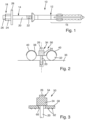
- Fig. 1 shows a fastening element 10 according to the invention with a dowel sleeve 12 made of plastic and a drive-in element 14.
- the drive-in element 14 spreads the dowel sleeve 12 in sections in the radial direction when the drive-in element 14 is driven into the dowel sleeve 12.
- the expansion area 16 of the dowel sleeve 12 is expanded in the radial direction and thereby anchored in an object, in particular in a borehole of the object, when the drive-in element 14 is driven into the dowel sleeve 12 Fig. 1 i.e. moved to the right into the dowel sleeve 12.
- the impact element 14 has a head 18 and a shaft 20.
- the shaft 20 is provided with a sawtooth thread 22 in sections.
- the sawtooth thread 22 is designed so that it can be moved to the right into the dowel sleeve 12 with a driving force. However, the sawtooth thread 22 then offers greater resistance against pulling the drive-in element 14 to the left out of the dowel sleeve.
- the drive-in element 14 can also be screwed into the dowel sleeve 12 using the sawtooth thread 22 and screwed out again. Even after driving in, the driving element 14 can be unscrewed from the dowel sleeve 12 again.
- the head 18 has an external drive formation 24 and a striking section 26.
- the external drive formation 24 is designed as an external hexagon in the illustrated embodiment.
- the impact section 26 has a cylindrical shape, in the illustrated embodiment a circular cylindrical shape.
- the impact section 26 adjoins the external drive training 24 in the direction of the free end of the head 18, in Fig. 1
- the impact section 26 is therefore arranged to the left of the external drive training 24.
- a contact section 28 is arranged between the head 18 and the shaft 20 of the impact element 14.
- the contact section 28 is disc-shaped and formed in one piece with the head 18 and the shaft 14.
- the contact section 28 has a significantly larger outer diameter than the shaft 20.
- the outer diameter of the contact section 28 is at least three times as large as the outer diameter of the shaft 20.
- the outer diameter of the contact section 28 is approximately five times as large as the outer diameter of the shaft 20 Shaft 20.
- a through hole is first formed in the workpiece and a drilled hole in the object.
- the drill hole in the object for example in a concrete floor, is usually as Blind hole formed.
- the fastening element 10 is then inserted through the through opening in the workpiece and in sections into the borehole of the object. This can be done to the extent that in Fig. 1 left end of the dowel sleeve 12 rests on the top of the workpiece and the expansion area 16 is completely arranged in the object.
- the workpiece can then be pre-fixed to the object, for example on a concrete floor, in a very simple manner by driving the drive-in element 14 into the dowel sleeve 12 with a hammer until the contact section 28 rests on the workpiece.
- the drive-in element 14 then spreads the expansion area 16 of the dowel sleeve 12, so that the fastening element is frictionally anchored in the drill hole in the object.
- the workpiece is then pre-fixed to the object.
- the holding force of the fastening element 10 according to the invention is significantly lower than the holding force that is required for final fastening of the workpiece to the object.
- the holding force that can be applied with the fastening element 10 according to the invention is smaller by a factor of 5, in particular a factor of 10, or by a factor between 5 and 10 than the holding force of a second fastening element, with which a final fixation is then carried out.
- the purpose of the fastening element according to the invention is to pre-fix the workpiece to the object in order to be able to set the second fastening elements in exactly the desired position in a simple manner or, for example, to be able to wait for an adhesive between the workpiece and the object to harden without the workpiece being in place must be recorded throughout the entire period.
- the fastening element 10 according to the invention can also be intended to fix the workpiece to the object in order to then be able to solder or weld the workpiece to the object.
- the impact section 26 When the drive-in element 14 is driven into the dowel sleeve 12, the impact occurs on the impact section 26.
- the impact section 26 inevitably deforms and increases its outer diameter.
- the impact section 26 serves as a sacrificial section.
- the outer diameter of the impact section 26 is smaller than the outer diameter of the external drive training 24. Even if the impact section 26 is deformed in such a way that its outer diameter becomes larger, this does not affect the possibility of being able to unscrew the drive element 14 again via the external drive training 24.
- a screw nut can be inserted over the external drive training 24, so that the drive-in element 14 can, for example, be unscrewed very quickly with a cordless screwdriver or the like.
- the outer diameter of the impact section is 10% to 25% smaller than the outer contour of the External drive training 24 inscribed circle. In such a case, there is no fear that the striking section 26 will increase its diameter so much when the impact element 14 is driven in that it protrudes beyond the outer contour of the external drive training 24.
- a prestressing force with which the expansion section 16 is pressed radially outwards against the inner wall of the borehole in the object is significantly reduced and in particular reduced to a value close to zero.
- the dowel sleeve 12 can thereby be pulled out of the drilled hole in a very simple manner and can also be pulled through the through hole in the workpiece. This can be done, for example, by placing on the contact section 28 in Fig. 1 is pulled to the left.
- a special tool is used with which the contact section is gripped in order to be able to pull the fastening element out of the workpiece and the object particularly quickly.
- second fastening elements are placed in order to finally fasten the workpiece to the object with the prescribed holding force.
- a second fastening element can then be inserted and fastened, for example, into the existing through opening and into the existing borehole.
- the advantage of the fastening element 10 according to the invention is that pre-fixation can be achieved very quickly by simply inserting and driving in.
- the holding force of the pre-fixation only needs to be so great that the final fixation of the workpiece to the object is possible, for example by setting drill holes and second fastening elements or by materially connecting the workpiece to the object.
- Fig. 2 shows a sectional sectional view of a fastening element 30 according to the invention according to a further embodiment of the invention.
- the dowel sleeve 12 is in Fig. 2 not shown for the sake of simplicity.
- the fastening element 30 is intended to pre-fix a structural steel structure 32 on a concrete floor 36.
- the drive-in element 34 of the fastening element 30 differs from the drive-in element 14 of the embodiment Fig. 1 just because a different one trained contact section 38 is provided.
- the striking section 26, the external drive training 24 and the shaft 20 of the impact element 34 are designed in exactly the same way as the impact element 14 Fig. 1 and will therefore not be explained again.
- the investment section 38 is in Fig. 2 shown only schematically and has two trough-shaped recesses 40.
- the trough-shaped recesses 40 are each intended to accommodate and fix a section of the structural steel structure 32.
- the representation of the Fig. 3 shows a fastening element 50 according to the invention according to a further embodiment in a sectional sectional view.
- the dowel sleeve 12 is not shown for the sake of simplicity.
- a driving element 54 has a head with a striking section 26 and an external drive section 24, which are of the same design as the driving element 14 of the Fig. 1 and therefore will not be explained again.
- the shaft 20 of the impact element 54 is also designed in the same way as the impact element 14 Fig. 1 .
- the dowel sleeve, not shown, also corresponds to the dowel sleeve 12 Fig. 1 .
- a contact section 58 is designed as a washer that is threaded onto the shaft 20.
- An outer diameter of the head on the underside of the external drive formation 24 is larger than a through opening 60 of the washer that forms the abutment section 58.
- An inner diameter of the through opening 60 is significantly larger, in particular 1.5 times to 3 times, especially 2 times, as large as the outer diameter of the shaft 20.
- the contact section 58 can thus be moved relative to the shaft. Even if the drive-in element 54 has already been driven into the dowel sleeve 12 and a pretensioning force is thereby exerted on the workpiece with the underside of the contact section 58, the workpiece can still be moved relative to the object, for example by lightly hitting the workpiece with a hammer laterally. The contact section 58 can then be moved together with the workpiece relative to the shaft 20.
- the underside of the contact section 58 facing the workpiece, not shown, is provided with a non-slip design.
- This anti-slip design is in the form of jagged projections 62.
- the jagged projections 62 dig into the top of the workpiece, for example made of wood consists.
- the contact section 58 is thereby fixed relative to the workpiece. When aligning the workpiece relative to the object, the contact section 58 can then be moved together with the workpiece relative to the shaft 20 of the impact element 54 and thus relative to the object, without a pre-fixation being completely canceled, since there is still a preload force by means of the fastening element 50 according to the invention is exerted on the workpiece.
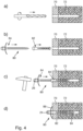
- Fig. 4 shows several steps in attaching a workpiece 70 to an object 72 with a fastening element 80 according to the invention according to a further embodiment of the invention.
- the workpiece 70 is designed, for example, as a railing or handrail section.
- the object 72 is a section of masonry, for example a building wall.
- step a a through hole is made in the workpiece 70 and after penetrating the workpiece 70, a blind hole is made in the object 72.
- step b after cleaning the borehole and the through opening, the fastening element 80 according to the invention is introduced into the through opening in the workpiece 70 and the borehole in the object 72. This is symbolized by two arrows above the dowel sleeve 82 and above the drive-in element 84.
- step c the dowel sleeve 82 has been inserted so far into the workpiece 70 and the object 72 that a head of the dowel sleeve 82 rests on an upper side of the workpiece 70 facing away from the object 72.
- the expansion section of the dowel sleeve 82 lies completely within the object 72.
- the driving element 84 is now driven into the dowel sleeve 82 with a few hammer blows on the striking section 26.
- the hammering or driving in of the hammering element 84 continues until the state in step d is reached.
- a contact section 88 of the fastening element 80 now rests on the top of the workpiece 70, which faces away from the object 72.
- the drive-in element 84 has completely penetrated the dowel sleeve 82 and thereby spread it radially outwards in the area in which the dowel sleeve 82 is arranged in the borehole in the object 72.
- the contact section 88 tensions the workpiece 70 against the object 72.
- the holding force that is exerted on the workpiece 70 by means of the fastening element 80 is significantly smaller than a holding force with which the workpiece 70 is finally attached to the workpiece Item 72 needs to be attached.
- the first holding force that is exerted with the fastening element 80 is smaller by a factor of 5 to a factor of 10 than the second holding force with which the workpiece 70 must be held on the object 72 in the finally assembled state.
- the second holding force is a holding force that is applied, for example, by a single second fastening element.
- the contact section 88 is designed as a sheet metal strip that is slightly angled at its free ends. The contact section 88 can thereby spring slightly in order to reliably pre-fix the workpiece 70 on the object 72.
- the object 70 is finally fixed to the object 72.
- the fastening element 80 can be removed. This is done by unscrewing the drive-in element 84 from the dowel sleeve 82 by means of the external drive design 24 at least until the drive-in element is completely or almost completely removed from the borehole in the object 72 and thus from the expansion area of the dowel sleeve 82.
- the expansion section of the dowel sleeve 82 is no longer pressed radially outwards and the drive-in element 84 can be easily pulled out of the borehole in the object 72 and the through opening in the workpiece 70 together with the dowel sleeve 82, in the illustration Fig. 4 to the left.
- a second fastening element can then be inserted into the drill hole in the object 72 and the through opening in the workpiece 70, for example a plastic dowel with a screw.
- the fastening element according to the invention and the method according to the invention a very simple and, above all, quick pre-fixation of a workpiece to an object is possible.
- the workpiece can thereby be held in the intended end position on the object in order to then be able to carry out a final attachment or fixation of the workpiece to the object.
- the final fixation can take place, for example, using second fastening elements, but also materially, for example by gluing, soldering or welding.
Abstract
Die Erfindung betrifft ein Befestigungselement mit einer Dübelhülse aus Kunststoff und einem Einschlagelement zum Eintreiben in die Dübelhülse, wobei das Einschlagelement die Dübelhülse beim Eintreiben des Einschlagelements in die Dübelhülse wenigstens abschnittsweise in radialer Richtung aufspreizt, wobei das Einschlagelement einen Schaft und einen Kopf aufweist, wobei der Schaft wenigstens abschnittsweise mit einer Gewindeausbildung und der Kopf mit einer Außenantriebsausbildung versehen ist, wobei der Kopf einen Schlagabschnitt aufweist, der sich ausgehend von der Außenantriebsausbildung bis zum freien Ende des Kopfs erstreckt, und wobei der Schlagabschnitt einen kleineren Außendurchmesser aufweist als die Außenantriebsausbildung.

Description
Die Erfindung betrifft ein Befestigungselement mit einer Dübelhülse aus Kunststoff und einem Einschlagelement zum Eintreiben in die Dübelhülse, wobei das Einschlagelement die Dübelhülse beim Eintreiben des Einschlagelements in die Dübelhülse wenigstens abschnittsweise in radialer Richtung aufspreizt. Die Erfindung betrifft auch ein Verfahren zum Befestigen eines Werkstücks an einem Gegenstand.The invention relates to a fastening element with a dowel sleeve made of plastic and a drive-in element for driving into the dowel sleeve, the drive-in element spreading the dowel sleeve at least in sections in the radial direction when the drive-in element is driven into the dowel sleeve. The invention also relates to a method for attaching a workpiece to an object.
Mit der Erfindung sollen ein Befestigungselement mit einer Dübelhülse aus Kunststoff und einem Einschlagelement zum Eintreiben in die Dübelhülse sowie ein Verfahren zum Befestigen eines Werkstücks an einem Gegenstand verbessert werden.The invention is intended to improve a fastening element with a dowel sleeve made of plastic and a drive-in element for driving into the dowel sleeve, as well as a method for fastening a workpiece to an object.
Erfindungsgemäß ist hierzu ein Befestigungselement mit einer Dübelhülse aus Kunststoff und einem Einschlagelement zum Eintreiben in die Dübelhülse vorgesehen, bei dem das Einschlagelement die Dübelhülse beim Eintreiben des Einschlagelements in die Dübelhülse wenigstens abschnittsweise in radialer Richtung aufspreizt, wobei das Einschlagelement einen Schaft und einen Kopf aufweist, wobei der Schaft wenigstens abschnittsweise mit einer Gewindeausbildung und der Kopf mit einer Außenantriebsausbildung versehen ist, wobei der Kopf einen Schlagabschnitt aufweist, der sich ausgehend von der Außenantriebsausbildung bis zum freien Ende des Kopfes erstreckt und wobei der Schlagabschnitt eine zylindrische Form und einen kleineren Außendurchmesser aufweist als die Außenantriebsausbildung.According to the invention, a fastening element with a dowel sleeve made of plastic and a drive-in element for driving into the dowel sleeve is provided, in which the drive-in element spreads the dowel sleeve at least partially in the radial direction when the drive-in element is driven into the dowel sleeve, the drive-in element having a shaft and a head, wherein the shaft is at least partially provided with a threaded formation and the head with an external drive formation, the head having a striking section which extends from the external drive training to the free end of the head and the striking section having a cylindrical shape and a smaller outer diameter than external drive training.
Das erfindungsgemäße Befestigungselement ist nach Art eines Schlagdübels oder Nageldübels ausschließlich für die vorläufige Befestigung von Werkstücken mit geringer Haltekraft vorgesehen. Durch einfaches Einschlagen des Einschlagelements kann ein schnelles Vorfixieren des Werkstücks erfolgen. Zweite Befestigungsmittel, die für die endgültige Befestigung vorgesehen sind, können dann nach dem Vorfixieren angeordnet werden. Beispielsweise kann aber auch die Vorfixierung mittels des erfindungsgemäßen Befestigungselements dazu dienen, das Werkstück bis zum Aushärten oder Trocknen eines Klebstoffs festzuhalten. Das Entfernen des erfindungsgemäßen Befestigungselements nach dem endgültigen Befestigen des Werkstücks am Gegenstand erfolgt dann in sehr einfacher Weise über die Außenantriebsausbildung, beispielsweise einen Außensechskant. Das Vorsehen eines separaten Schlagabschnitts ermöglicht es, das erfindungsgemäße Befestigungselement auch mit hoher Schlagkraft eintreiben zu können, ohne dass zu befürchten ist, dass die Außenantriebsausbildung dabei Schaden nimmt. Der Schlagabschnitt wird beim Einschlagen möglicherweise deformiert und vergrößert seinen Außendurchmesser.The fastening element according to the invention is intended in the manner of an impact dowel or nail dowel exclusively for the temporary fastening of workpieces with low holding force. By simply driving in the driving element, the workpiece can be quickly pre-fixed. Second fasteners intended for final fastening can then be arranged after pre-fixing. For example, the pre-fixation by means of the fastening element according to the invention can also serve to hold the workpiece in place until an adhesive has hardened or dried. The removal of the fastening element according to the invention after the workpiece has finally been fastened to the object is then carried out in a very simple manner via the external drive design, for example an external hexagon. The provision of a separate impact section makes it possible to drive in the fastening element according to the invention even with high impact force, without the fear that the external drive design will be damaged. The impact portion may be deformed upon impact and increase its outer diameter.
Da der Außendurchmesser des Schlagabschnitts aber kleiner ist als die Außenantriebsausbildung, bleibt auch bei einer gewissen Deformation der Außendurchmesser des Schlagabschnitts noch kleiner als der Außendurchmesser der Antriebsausbildung, so dass ein problemloses Entfernen des Befestigungselements durch Ausschrauben des Einschlagelements möglich ist. Beispielsweise ist der Außendurchmesser des Schlagabschnitts kleiner als ein gedachter, in die Außenkontur der Außenantriebsausbildung einbeschriebener Kreis der Außenantriebsausbildung, insbesondere 10% bis 25% kleiner als der einbeschriebene Kreis der Außenantriebsausbildung. Das Einschlagelement weist üblicherweise einen Schaft in Form einer Nagelschraube mit Sägezahngewinde auf. Die Dübelhülse kann ebenfalls auf eine Nagelschraube abgestimmt sein. Mit dem erfindungsgemäßen Befestigungselement lässt sich eine sehr schnelle Vorfixierung eines Werkstücks erreichen. Beispielsweise kann bei der Befestigung eines Geländers auf einem Betonboden das Geländer sehr schnell und mit wenigen Hammerschlägen vorfixiert werden. Die endgültige Befestigung wird dann dadurch vorgenommen, dass Löcher durch einen Bodenabschnitt des Geländers hindurch in den Betonboden eingebohrt werden und das Geländer dann mittels geeigneter Befestigungsdübel, beispielsweise Chemiedübel, die in den Beton eingeklebt werden und passenden Schrauben, oder auch Rahmendübel, erfolgt. Nach dem endgültigen Befestigen des Geländers werden die erfindungsgemäßen Befestigungselemente dann wieder entfernt und beispielsweise werden in die Durchgangsöffnungen im Bodenabschnitt des Geländers, aus dem die erfindungsgemäßen Befestigungselemente herausgeschraubt werden, dann auch zweite Befestigungselemente für die endgültige Befestigung eingeschraubt. Selbstverständlich können im Wesentlichen beliebige Werkstücke an beliebigen Gegenständen mit dem erfindungsgemäßen Befestigungselement vorfixiert werden, beispielsweise Geländer an Bauwerken, Fensterrahmen an Fensterlaibungen, Türzargen am Mauerwerk oder dergleichen. Wesentlich ist, dass mittels der erfindungsgemäßen Befestigungselemente eine extrem schnelle Vorfixierung durch wenige Hammerschläge erfolgen kann, wobei die Befestigungskraft beziehungsweise Haltekraft, die durch die erfindungsgemäßen Befestigungselemente ausgeübt wird, deutlich kleiner ist als die Befestigungskraft oder Haltekraft, die bei der endgültigen Befestigung erforderlich ist. Beispielsweise muss ein Geländer so sicher befestigt sein, dass es auch dann, wenn sich eine Person gegen das Geländer wirft, nicht abbricht. Mit dem erfindungsgemäßen Befestigungselement ist eine so große Haltekraft nicht erforderlich, da das erfindungsgemäße Befestigungselement lediglich für die Vorfixierung des Geländers vorgesehen ist.However, since the outer diameter of the impact section is smaller than the external drive design, even with a certain deformation, the outer diameter of the impact section remains smaller than the outer diameter of the drive design, so that the fastening element can be easily removed by unscrewing the impact element. For example, the outer diameter of the impact section is smaller than an imaginary circle of the external drive training inscribed in the outer contour of the external drive training, in particular 10% to 25% smaller than the inscribed circle of the external drive training. The drive-in element usually has a shaft in the form of a nail screw with a sawtooth thread. The dowel sleeve can also be matched to a nail screw. With the fastening element according to the invention, a workpiece can be pre-fixed very quickly. For example, when attaching a railing to a concrete floor, the railing can be pre-fixed very quickly and with just a few blows of a hammer. The final fastening is then carried out by drilling holes through a bottom section of the railing into the concrete floor and then attaching the railing using suitable fastening dowels, for example chemical dowels, which are glued into the concrete and suitable screws, or frame dowels. After the railing has been finally fastened, the fastening elements according to the invention are then removed again and, for example, second fastening elements for the final fastening are then screwed into the through openings in the bottom section of the railing, from which the fastening elements according to the invention are screwed out. Of course, essentially any workpieces can be pre-fixed to any objects using the fastening element according to the invention, for example railings on buildings, window frames on window reveals, door frames on masonry or the like. It is important that the fastening elements according to the invention can be used to pre-fix extremely quickly by just a few hammer blows, with the fastening force or holding force exerted by the fastening elements according to the invention being significantly smaller than the fastening force or holding force required for the final fastening. For example, a railing must be fastened so securely that it does not break off even if a person throws themselves against the railing. With the fastening element according to the invention, such a large holding force is not required, since the fastening element according to the invention is only intended for pre-fixing the railing.
In Weiterbildung der Erfindung weist das Befestigungselement einen Anlageabschnitt zwischen dem Kopf und dem Schaft des Einschlagelements auf, wobei ein Außendurchmesser des Anlageabschnitts mindestens dreimal so groß ist wie ein Außendurchmesser des Schafts des Einschlagelements.In a further development of the invention, the fastening element has a contact section between the head and the shaft of the drive-in element, an outer diameter of the contact section being at least three times as large as an outer diameter of the shaft of the drive-in element.
Auf diese Weise kann mittels des Anlageabschnitts eine zuverlässige vorläufige Fixierung eines Werkstücks an einem Gegenstand erfolgen. Dies beispielsweise auch dann, wenn eine Durchgangsbohrung im Werkstück deutlich größer ist als der Außendurchmesser des Schafts des Befestigungselements. Durch den Anlageabschnitt kann dann dennoch eine Vorspannkraft auf das Werkstück ausgeübt werden, die das Werkstück für ein Vorfixieren dann gegen den Gegenstand presst.In this way, a workpiece can be reliably temporarily fixed to an object by means of the contact section. This is also the case, for example, if a through hole in the workpiece is significantly larger than the outer diameter of the shaft of the fastening element. The contact section can then still exert a pretensioning force on the workpiece, which then presses the workpiece against the object for pre-fixing.
In Weiterbildung der Erfindung ist der Anlageabschnitt in Form einer auf den Schaft aufgefädelten Unterlegscheibe ausgebildet.In a further development of the invention, the contact section is designed in the form of a washer threaded onto the shaft.
Auf diese Weise lässt sich der Anlageabschnitt in sehr einfacher Weise realisieren.In this way, the investment section can be implemented in a very simple manner.
In Weiterbildung der Erfindung hat eine Durchgangsöffnung in der Unterlegscheibe, durch die sich der Schaft hindurcherstreckt, einen Durchmesser, der um mindestens 10% bis 100% größer ist als ein Außendurchmesser des Schafts.In a further development of the invention, a through opening in the washer, through which the shaft extends, has a diameter that is at least 10% to 100% larger than an outer diameter of the shaft.
Die Unterlegscheibe umgibt den Schaft somit mit vergleichsweise großem Spiel. Dadurch kann das Werkstück relativ zum Gegenstand noch ausgerichtet werden, auch wenn das Einschlagelement des erfindungsgemäßen Befestigungselements bereits eingeschlagen ist. Der Kopf des Einschlagelements muss selbstverständlich einen größeren Durchmesser aufweisen als die Durchgangsöffnung in der Unterlegscheibe. Die Vorspannkraft, die von dem erfindungsgemäßen Befestigungselement auf das Werkstück im Rahmen der Vorfixierung aufgebracht wird, ist noch so gering, dass das Werkstück, beispielsweise mit seitlichen Hammerschlägen, relativ zum Gegenstand ausgerichtet werden kann.The washer therefore surrounds the shaft with comparatively large play. As a result, the workpiece can still be aligned relative to the object, even if the drive-in element of the fastening element according to the invention has already been driven in. The head of the impact element must of course have a larger diameter than the through opening in the washer. The pretensioning force that is applied to the workpiece by the fastening element according to the invention as part of the pre-fixing is still so low that the workpiece can be aligned relative to the object, for example with lateral hammer blows.
In Weiterbildung der Erfindung ist der Anlageabschnitt einstückig mit dem Einschlagelement ausgebildet.In a further development of the invention, the contact section is formed in one piece with the impact element.
In Weiterbildung der Erfindung weist der Anlageabschnitt wenigstens eine senkrecht zum Schaft verlaufende rinnenartige Ausformung auf.In a further development of the invention, the contact section has at least one channel-like shape running perpendicular to the shaft.
Mittels des erfindungsgemäßen Befestigungselements können dadurch in sehr einfacher Weise Baustahlstäbe oder andere zylindrische Werkstücke in sehr einfacher Weise und dabei sicher vorfixiert werden. Beispielsweise können Baustahlstäbe oder auch Verstärkungskonstruktionen aus Baustahlstäben, sogenannte Moniereisen, mit den erfindungsgemäßen Befestigungselementen in sehr einfacher Weise vorfixiert werden, bevor diese Baustahlstäbe dann mit flüssigem Beton umschlossen werden.By means of the fastening element according to the invention, structural steel bars or other cylindrical workpieces can be pre-fixed in a very simple and secure manner. For example, structural steel rods or reinforcing structures made of structural steel rods, so-called monier irons, can be pre-fixed in a very simple manner with the fastening elements according to the invention before these structural steel rods are then enclosed with liquid concrete.
In Weiterbildung der Erfindung weist der Anlageabschnitt eine dem Kopf abgewandte rutschhemmende Unterseite auf.In a further development of the invention, the contact section has an anti-slip underside facing away from the head.
Beispielsweise ist eine Gummierung oder eine Scheibe aus elastischem gummiartigen Material vorgesehen. Beispielsweise kann der Anlageabschnitt aber auch eine raue Unterseite, eine Unterseite mit vorragenden Vorsprüngen oder Spitzen aufweisen. Die rutschhemmende Unterseite dient der zuverlässigen Vorfixierung eines Werkstücks an einem Gegenstand. Die rutschhemmende Unterseite ist vorteilhafterweise auf den Werkstoff des vorzufixierenden Werkstücks abgestimmt. Als rutschhemmend wird eine Unterseite des Unterlagenabschnitts bezeichnet, die im Vergleich mit einer glatten Metallunterseite des Anlageabschnitts einen höheren Reibungskoeffizienten zwischen der Unterseite des Anlagenabschnitts und der Oberseite des Werkstücks bewirkt.For example, a rubber coating or a disc made of elastic rubber-like material is provided. For example, the contact section can also have a rough underside, an underside with protruding projections or points. The non-slip underside is used to reliably pre-fix a workpiece to an object. The anti-slip underside is advantageously matched to the material of the workpiece to be pre-fixed. An underside of the support section is referred to as anti-slip, which, compared to a smooth metal underside of the contact section, causes a higher coefficient of friction between the underside of the contact section and the top of the workpiece.
Das der Erfindung zugrunde liegende Problem wird auch durch ein Verfahren zum Befestigen eines Werkstücks an einem Gegenstand gelöst, bei dem die folgenden Schritte vorgesehen sind: Einbringen eines Bohrlochs in den Gegenstand und Einbringen einer Durchgangsbohrung in das Werkstück, Einstecken eines erfindungsgemäßen Befestigungselements in die Durchgangsbohrung und das Bohrloch, Einschlagen des Einschlagelements in die Dübelhülse und dadurch vorläufiges Fixieren des Werkstücks an dem Gegenstand, wobei eine erste Haltekraft, mit der das Befestigungselement vor dem Versagen beaufschlagt werden kann, kleiner ist als eine zweite Haltekraft, mit der ein zweites Befestigungselement, das für eine endgültige Befestigung des Werkstücks am Gegenstand vorgesehen ist, beaufschlagt werden kann.The problem on which the invention is based is also solved by a method for fastening a workpiece to an object, in which the following steps are provided: introducing a drill hole into the object and introducing a through hole into the workpiece, inserting a fastening element according to the invention into the through hole and the drill hole, hammering the drive-in element into the dowel sleeve and thereby temporarily fixing the workpiece to the object, wherein a first holding force with which the fastening element can be applied before failure is smaller than a second holding force with which a second fastening element, which is for a final attachment of the workpiece to the object is provided, can be acted upon.
Das erfindungsgemäße Befestigungselement ist somit ausschließlich für die Vorfixierung vorgesehen. Diese Vorfixierung kann problemlos und extrem schnell durch einfaches Einstecken des Befestigungselements und Einschlagen des Einschlagelements in die Dübelhülse erfolgen. Die Haltekraft, die das erfindungsgemäße Befestigungselement dabei aufbringen kann, muss lediglich so groß sein, dass das Werkstück vorfixiert ist, um dann die zweiten Befestigungselemente, die für die endgültige Befestigung vorgesehen sind, anbringen zu können. Beispielsweise können die erfindungsgemäßen Befestigungselemente auch für eine Vorfixierung des Werkstücks verwendet werden und werden dann wieder entfernt, sobald eine stoffschlüssige Verbindung, beispielsweise durch Kleben, Löten oder Schweißen, zwischen dem Werkstück und dem Gegenstand erfolgt ist.The fastening element according to the invention is therefore intended exclusively for pre-fixation. This pre-fixation can be done easily and extremely quickly by simply inserting the fastening element and driving the drive-in element into the dowel sleeve. The holding force that the fastening element according to the invention can apply only has to be so great that the workpiece is pre-fixed in order to then be able to attach the second fastening elements that are intended for the final fastening. For example, the fastening elements according to the invention can also be used for pre-fixing the workpiece and are then removed again as soon as a cohesive connection, for example by gluing, soldering or welding, has taken place between the workpiece and the object.
In Weiterbildung der Erfindung ist die erste Haltekraft um mindestens den Faktor 5, insbesondere den Faktor 10, kleiner als die zweite Haltekraft.In a further development of the invention, the first holding force is smaller than the second holding force by at least a factor of 5, in particular a factor of 10.
Wie ausgeführt, geht es bei dem erfindungsgemäßen Befestigungselement lediglich um eine Vorfixierung. Gegebenenfalls ist die erste Haltekraft so gering, dass das Werkstück, beispielsweise durch seitliche Hammerschläge, noch relativ zum Gegenstand ausgerichtet werden kann. Mittels der Vorfixierung soll das Werkstück nur in Position gehalten werden, so dass die zweiten Befestigungsmittel gesetzt werden können und/oder eine stoffschlüssige Verbindung erfolgen kann.As stated, the fastening element according to the invention is merely a matter of pre-fixing. If necessary, the first holding force is so low that the workpiece can still be aligned relative to the object, for example by hitting it sideways with a hammer. By means of the pre-fixing, the workpiece should only be held in position so that the second fastening means can be set and/or a material connection can be made.
In Weiterbildung der Erfindung ist das Setzen wenigstens des zweiten Befestigungselements und/oder das stoffschlüssige Verbinden des Werkstücks und des Gegenstandes und dadurch das endgültige Fixieren des Werkstücks am Gegenstand vorgesehen.In a further development of the invention, the setting of at least the second fastening element and/or the cohesive connection of the workpiece and the object and thereby the final fixing of the workpiece to the object is provided.
In Weiterbildung der Erfindung ist das Entfernen des Befestigungselements nach dem Setzen wenigstens des zweiten Befestigungselements und/oder nach dem stoffschlüssigen Verbinden vorgesehen.In a further development of the invention, the removal of the fastening element is provided after setting at least the second fastening element and/or after the material connection.
Weitere Merkmale und Vorteile der Erfindung ergeben sich aus den Ansprüchen und der folgenden Beschreibung bevorzugter Ausführungsformen der Erfindung im Zusammenhang mit den Zeichnungen. Einzelmerkmale der unterschiedlichen, in den Zeichnungen dargestellten und/oder der Beschreibung beschriebenen Ausführungsformen können dabei in beliebiger Weise miteinander kombiniert werden, ohne den Rahmen der Erfindung zu überschreiten. Dies gilt auch für die Kombination von Einzelmerkmalen ohne weitere Einzelmerkmale, mit denen sie im Zusammenhang gezeigt und/oder beschrieben sind. In den Zeichnungen zeigen:
- Fig. 1
- eine Seitenansicht eines erfindungsgemäßen Befestigungselements gemäß einer ersten Ausführungsform,
- Fig. 2
- eine abschnittsweise Ansicht eines erfindungsgemäßen Befestigungselements gemäß einer zweiten Ausführungsform,
- Fig. 3
- eine abschnittsweise Schnittansicht eines erfindungsgemäßen Befestigungselements gemäß einer dritten Ausführungsform, und
- Fig. 4
- mehrere aufeinanderfolgende Verfahrensschritte beim Befestigen eines Werkstücks an einem Gegenstand mit einem erfindungsgemäßen Befestigungselement.
- Fig. 1
- a side view of a fastening element according to the invention according to a first embodiment,
- Fig. 2
- a sectional view of a fastening element according to the invention according to a second embodiment,
- Fig. 3
- a sectional sectional view of a fastening element according to the invention according to a third embodiment, and
- Fig. 4
- several successive process steps when attaching a workpiece to an object with a fastening element according to the invention.
Das Einschlagelement 14 weist einen Kopf 18 und einen Schaft 20 auf. Der Schaft 20 ist abschnittsweise mit einem Sägezahngewinde 22 versehen. Das Sägezahngewinde 22 ist so ausgebildet, dass es mit einer Eintreibkraft nach rechts in die Dübelhülse 12 hineinbewegt werden kann. Gegen ein Ausziehen des Einschlagelements 14 nach links aus der Dübelhülse heraus bietet das Sägezahngewinde 22 dann aber einen größeren Widerstand. Das Einschlagelement 14 kann mittels des Sägezahngewindes 22 auch in die Dübelhülse 12 eingeschraubt und wieder aus dieser herausgeschraubt werden. Auch nach dem Einschlagen kann das Einschlagelement 14 wieder aus der Dübelhülse 12 herausgeschraubt werden.The
Der Kopf 18 weist eine Außenantriebsausbildung 24 auf und einen Schlagabschnitt 26. Die Außenantriebsausbildung 24 ist bei der dargestellten Ausführungsform als Außensechskant ausgebildet. Der Schlagabschnitt 26 weist eine zylindrische Form auf, bei der dargestellten Ausführungsform eine kreiszylindrische Form. Der Schlagabschnitt 26 schließt sich an die Außenantriebsausbildung 24 in Richtung auf das freie Ende des Kopfes 18 an, in
Zwischen dem Kopf 18 und dem Schaft 20 des Einschlagelements 14 ist ein Anlageabschnitt 28 angeordnet. Der Anlageabschnitt 28 ist bei der dargestellten Ausführungsform scheibenförmig ausgebildet und einstückig mit dem Kopf 18 sowie dem Schaft 14 ausgebildet. Der Anlageabschnitt 28 weist einen wesentlich größeren Außendurchmesser auf als der Schaft 20. Speziell ist der Außendurchmesser des Anlageabschnitts 28 mindestens dreimal so groß wie der Außendurchmesser des Schafts 20. Bei der dargestellten Ausführungsform ist der Außendurchmesser des Anlageabschnitts 28 etwa fünfmal so groß wie der Außendurchmesser des Schafts 20. Mit dem Anlageabschnitt 28 wird eine Vorspannkraft zum Vorfixieren auf ein Werkstück ausgeübt.A
Zum Befestigen eines Werkstücks an einem Gegenstand wird zunächst eine Durchgangsbohrung in dem Werkstück und ein Bohrloch in dem Gegenstand ausgebildet. Das Bohrloch in dem Gegenstand, beispielsweise in einem Betonboden, ist üblicherweise als Sackloch ausgebildet. Das Befestigungselement 10 wird dann durch die Durchgangsöffnung im Werkstück hindurch und abschnittsweise in das Bohrloch des Gegenstands eingesteckt. Dies kann soweit erfolgen, dass das in
Die Haltekraft des erfindungsgemäßen Befestigungselements 10 ist dabei deutlich geringer als die Haltekraft, die für eine endgültige Befestigung des Werkstücks am Gegenstand benötigt wird. Beispielsweise ist die Haltekraft, die mit dem erfindungsgemäßen Befestigungselement 10 aufgebracht werden kann, um den Faktor 5, insbesondere den Faktor 10, oder um einen Faktor zwischen 5 und 10 kleiner als die Haltekraft eines zweiten Befestigungselements, mit dem dann eine endgültige Fixierung erfolgt. Sinn und Zweck des erfindungsgemäßen Befestigungselements ist die Vorfixierung des Werkstücks am Gegenstand, um die zweiten Befestigungselemente an exakt der gewünschten Position in einfacher Weise setzen zu können oder auch um beispielsweise das Aushärten eines Klebstoffs zwischen Werkstück und Gegenstand abwarten zu können, ohne dass das Werkstück während der gesamten Zeit festgehalten werden muss. Beispielsweise kann das erfindungsgemäße Befestigungselement 10 auch dafür vorgesehen sein, das Werkstück am Gegenstand zu fixieren, um dann das Werkstück mit dem Gegenstand verlöten oder verschweißen zu können.The holding force of the
Beim Eintreiben des Einschlagelements 14 in die Dübelhülse 12 erfolgen die Schläge auf den Schlagabschnitt 26. Der Schlagabschnitt 26 verformt sich dabei zwangsläufig und vergrößert seinen Außendurchmesser. Der Schlagabschnitt 26 dient als Opferabschnitt. Der Außendurchmesser des Schlagabschnitts 26 ist kleiner als der Außendurchmesser der Außenantriebsausbildung 24. Selbst wenn sich also der Schlagabschnitt 26 so deformiert, dass sein Außendurchmesser größer wird, so beeinträchtigt dies nicht die Möglichkeit, das Einschlagelement 14 über die Außenantriebsausbildung 24 wieder ausschrauben zu können. Speziell kann eine Schraubnuss über die Außenantriebsausbildung 24 gesteckt werden, so dass das Einschlagelement 14 beispielsweise sehr schnell mit einem Akkuschrauber oder dergleichen ausgeschraubt werden kann. Vorteilhafterweise ist der Außendurchmesser des Schlagabschnitts um 10% bis 25% kleiner als ein in die Außenkontur der Außenantriebsausbildung 24 einbeschriebener Kreis. In einem solchen Fall ist nicht zu befürchten, dass der Schlagabschnitt 26 beim Eintreiben des Einschlagelements 14 seinen Durchmesser so stark vergrößert, dass er über die Außenkontur der Außenantriebsausbildung 24 hinausragt.When the drive-in
Beim Ausschrauben des Einschlagelements 14 aus der Dübelhülse 12 wird eine Vorspannkraft, mit der der Spreizabschnitt 16 radial nach außen gegen die Innenwand des Bohrlochs in dem Gegenstand gepresst wird, wesentlich verringert und insbesondere auf einen Wert nahe null verringert. Die Dübelhülse 12 kann dadurch in sehr einfacher Weise aus dem Bohrloch herausgezogen werden und auch durch das Durchgangsloch im Werkstück hindurchgezogen werden. Dies kann beispielsweise dadurch erfolgen, dass an dem Anlageabschnitt 28 in
Während das Werkstück mit dem erfindungsgemäßen Befestigungselement 10 an dem Gegenstand vorfixiert ist, werden zweite Befestigungselemente gesetzt, um das Werkstück endgültig und mit der vorgeschriebenen Haltekraft am Gegenstand zu befestigen. Nach dem Entfernen des erfindungsgemäßen Befestigungselements 10 kann dann beispielsweise in die vorhandene Durchgangsöffnung und in das vorhandene Bohrloch ein zweites Befestigungselement eingesetzt und befestigt werden.While the workpiece is pre-fixed to the object with the
Der Vorteil des erfindungsgemäßen Befestigungselements 10 liegt darin, dass durch einfaches Einstecken und Einschlagen sehr schnell eine Vorfixierung erzielt werden kann. Die Haltekraft der Vorfixierung muss dabei nur so groß sein, dass die endgültige Fixierung des Werkstücks am Gegenstand möglich ist, beispielsweise durch Setzen von Bohrlöchern und zweiten Befestigungselementen oder durch stoffschlüssiges Verbinden des Werkstücks mit dem Gegenstand.The advantage of the
Das Einschlagelement 34 des Befestigungselements 30 unterscheidet sich vom Einschlagelement 14 der Ausführungsform der
Der Anlageabschnitt 38 ist in
Nach der Vorfixierung der Baustahlkonstruktion 32 auf dem Betonboden 36 mit dem erfindungsgemäßen Befestigungselement 30 wird flüssiger Beton auf den Betonboden 36 aufgebracht. Nach dem Aushärten ist die Baustahlkonstruktion 32 dadurch sicher fixiert. Das erfindungsgemäße Befestigungselement 30 bleibt in diesem Fall in dem aufgegossenen Beton.After the
Die Darstellung der
Ein Anlageabschnitt 58 ist als Unterlegscheibe ausgebildet, die auf den Schaft 20 aufgefädelt ist. Ein Außendurchmesser des Kopfes an der Unterseite der Außenantriebsausbildung 24 ist größer als eine Durchgangsöffnung 60 der Unterlegscheibe, die den Anlageabschnitt 58 bildet. Ein Innendurchmesser der Durchgangsöffnung 60 ist deutlich größer, insbesondere 1,5 mal bis 3 mal, speziell 2 mal, so groß wie der Außendurchmesser des Schafts 20. Der Anlageabschnitt 58 kann somit relativ zum Schaft bewegt werden. Auch dann, wenn das Einschlagelement 54 bereits in die Dübelhülse 12 eingeschlagen ist und dadurch mit der Unterseite des Anlageabschnitts 58 eine Vorspannkraft auf das Werkstück ausgeübt wird, kann das Werkstück noch relativ zu dem Gegenstand bewegt werden, beispielsweise durch leichte Hammerschläge seitlich gegen das Werkstück. Der Anlageabschnitt 58 kann nämlich dann zusammen mit dem Werkstück relativ zum Schaft 20 verschoben werden.A
Eine dem in
Im Schritt a wird in das Werkstück 70 eine Durchgangsbohrung eingebracht und nach dem Durchdringen des Werkstücks 70 wird in den Gegenstand 72 ein Sackloch eingebracht.In step a, a through hole is made in the
Im Schritt b wird nach dem Reinigen des Bohrlochs und der Durchgangsöffnung das erfindungsgemäße Befestigungselement 80 in die Durchgangsöffnung im Werkstück 70 und das Bohrloch im Gegenstand 72 eingebracht. Dies ist durch zwei Pfeile oberhalb der Dübelhülse 82 und oberhalb des Einschlagelements 84 symbolisiert.In step b, after cleaning the borehole and the through opening, the
Im Schritt c ist die Dübelhülse 82 so weit in das Werkstück 70 und den Gegenstand 72 eingesteckt worden, dass ein Kopf der Dübelhülse 82 auf einer dem Gegenstand 72 abgewandten Oberseite des Werkstücks 70 aufliegt. Der Spreizabschnitt der Dübelhülse 82 liegt vollständig innerhalb des Gegenstands 72.In step c, the
In diesem Zustand wird nun das Einschlagelement 84 mit einigen Hammerschlägen auf den Schlagabschnitt 26 in die Dübelhülse 82 eingetrieben. Das Einschlagen beziehungsweise Eintreiben des Einschlagelements 84 erfolgt so lange, bis der Zustand im Schritt d erreicht ist. Ein Anlageabschnitt 88 des Befestigungselements 80 liegt nun auf der Oberseite des Werkstücks 70 auf, die dem Gegenstand 72 abgewandt ist. Das Einschlagelement 84 hat die Dübelhülse 82 vollständig durchdrungen und diese dadurch in dem Bereich, in dem die Dübelhülse 82 in dem Bohrloch im Gegenstand 72 angeordnet ist, radial nach außen aufgespreizt. Der Anlageabschnitt 88 spannt das Werkstück 70 gegen den Gegenstand 72 vor.In this state, the driving
Die Haltekraft, die mittels des Befestigungselements 80 auf das Werkstück 70 ausgeübt wird, ist dabei wesentlich kleiner als eine Haltekraft, mit der das Werkstück 70 endgültig an dem Gegenstand 72 befestigt werden muss. Beispielsweise ist die erste Haltekraft, die mit dem Befestigungselement 80 ausgeübt wird, um den Faktor 5 bis den Faktor 10 kleiner als die zweite Haltekraft, mit der das Werkstück 70 im endgültig montierten Zustand an dem Gegenstand 72 gehalten werden muss. Die zweite Haltekraft ist dabei eine Haltekraft, die beispielsweise durch ein einziges zweites Befestigungselement aufgebracht wird.The holding force that is exerted on the
Der Anlageabschnitt 88 ist als Blechstreifen ausgebildet, der an seinen freien Enden leicht abgewinkelt ist. Der Anlageabschnitt 88 kann dadurch leicht federn, um das Werkstück 70 zuverlässig am Gegenstand 72 vorzufixieren.The
Nachdem im Zustand d das Werkstück 70 am Gegenstand 72 vorfixiert ist, wird der Gegenstand 70 endgültig am Gegenstand 72 fixiert. Abschließend kann das Befestigungselement 80 entfernt werden. Dies geschieht dadurch, dass das Einschlagelement 84 mittels der Außenantriebsausbildung 24 aus der Dübelhülse 82 wenigstens so weit herausgeschraubt wird, bis das Einschlagelement vollständig oder fast vollständig aus dem Bohrloch im Gegenstand 72 und damit aus dem Spreizbereich der Dübelhülse 82 entfernt ist. Dadurch wird auch der Spreizabschnitt der Dübelhülse 82 nicht mehr radial nach außen gedrückt und das Einschlagelement 84 kann in einfacher Weise zusammen mit der Dübelhülse 82 aus dem Bohrloch im Gegenstand 72 und der Durchgangsöffnung im Werkstück 70 herausgezogen werden, in der Darstellung der
In das Bohrloch im Gegenstand 72 und die Durchgangsöffnung im Werkstück 70 kann dann ein zweites Befestigungselement eingesetzt werden, beispielsweise ein Kunststoffdübel mit einer Schraube.A second fastening element can then be inserted into the drill hole in the
Mit dem erfindungsgemäßen Befestigungselement und dem erfindungsgemäßen Verfahren ist eine sehr einfache und vor allem schnelle Vorfixierung eines Werkstücks an einem Gegenstand möglich. Das Werkstück kann dadurch in der vorgesehenen Endposition am Gegenstand gehalten werden, um dann eine endgültige Befestigung oder Fixierung des Werkstücks am Gegenstand vornehmen zu können. Die endgültige Fixierung kann beispielsweise durch zweite Befestigungselemente erfolgen, aber auch stoffschlüssig, beispielsweise durch Kleben, Löten oder Schweißen.With the fastening element according to the invention and the method according to the invention, a very simple and, above all, quick pre-fixation of a workpiece to an object is possible. The workpiece can thereby be held in the intended end position on the object in order to then be able to carry out a final attachment or fixation of the workpiece to the object. The final fixation can take place, for example, using second fastening elements, but also materially, for example by gluing, soldering or welding.
Claims (11)
Applications Claiming Priority (1)
| Application Number | Priority Date | Filing Date | Title |
|---|---|---|---|
| DE102022208997.9A DE102022208997A1 (en) | 2022-08-30 | 2022-08-30 | Fastener and method of fastening |
Publications (1)
| Publication Number | Publication Date |
|---|---|
| EP4332391A1 true EP4332391A1 (en) | 2024-03-06 |
Family
ID=87845942
Family Applications (1)
| Application Number | Title | Priority Date | Filing Date |
|---|---|---|---|
| EP23193557.8A Pending EP4332391A1 (en) | 2022-08-30 | 2023-08-25 | Fastening element and method for fastening |
Country Status (2)
| Country | Link |
|---|---|
| EP (1) | EP4332391A1 (en) |
| DE (1) | DE102022208997A1 (en) |
Citations (1)
| Publication number | Priority date | Publication date | Assignee | Title |
|---|---|---|---|---|
| EP1518056B1 (en) * | 2002-07-02 | 2007-04-18 | Fischerwerke Artur Fischer GmbH & Co. KG | Plastic expanding plug |
Family Cites Families (5)
| Publication number | Priority date | Publication date | Assignee | Title |
|---|---|---|---|---|
| DE3018975A1 (en) | 1980-05-17 | 1981-11-26 | Groh, Karl-Friedrich, 7118 Künzelsau | Screw and dowel for panel fixing - includes screw with threaded and plain parts forced into dowel by hammer |
| DE4123754C2 (en) | 1991-07-18 | 1993-11-04 | Bettermann Obo Ohg | CABLE CLAMP |
| DE20200292U1 (en) | 2002-01-10 | 2002-03-28 | Friedhelm Nolte Gmbh | Fastening element for a component that can be fastened to a wall |
| DE102004052184A1 (en) | 2004-10-27 | 2006-05-04 | Fischerwerke Artur Fischer Gmbh & Co. Kg | Nail anchor has shaft and a flange which are expandable and have a wall thickness reduction on a peripheral side for expandability and a slot on a peripheral side |
| JP6919406B2 (en) | 2017-08-10 | 2021-08-18 | トヨタ自動車株式会社 | Vehicle side structure |
-
2022
- 2022-08-30 DE DE102022208997.9A patent/DE102022208997A1/en active Pending
-
2023
- 2023-08-25 EP EP23193557.8A patent/EP4332391A1/en active Pending
Patent Citations (1)
| Publication number | Priority date | Publication date | Assignee | Title |
|---|---|---|---|---|
| EP1518056B1 (en) * | 2002-07-02 | 2007-04-18 | Fischerwerke Artur Fischer GmbH & Co. KG | Plastic expanding plug |
Also Published As
| Publication number | Publication date |
|---|---|
| DE102022208997A1 (en) | 2024-02-29 |
Similar Documents
| Publication | Publication Date | Title |
|---|---|---|
| DE10012644A1 (en) | Dowels | |
| DE2849139C2 (en) | Method for setting fasteners in concrete | |
| EP0676551B1 (en) | Fastening element driven into hard parent materials by means of explosive-driven setting tools | |
| DE3607607A1 (en) | FIXING SEALING SHEETS AND / OR INSULATION PANELS ON THE FLAT ROOF AND THEREFORE SPECIFIC FASTENING DEVICE | |
| DE19705202B4 (en) | Method for fixing wooden construction parts in front of a concrete wall or wall | |
| DE202004015509U1 (en) | A screw plug that can be screwed in in one operation | |
| EP0724085A1 (en) | Fastening anchor with undercut and form-locking action | |
| EP4332391A1 (en) | Fastening element and method for fastening | |
| EP0728882B1 (en) | Fastening element for fastening thick plates on structural components | |
| DE3020907C2 (en) | ||
| EP2151589B1 (en) | Telescopic cover | |
| EP2927509A1 (en) | Fixing method | |
| EP2977528B1 (en) | Reinforcement assembly for a structure and method of reinforcing a structure having such a reinforcement assembly | |
| DE3843392A1 (en) | METHOD FOR SETTING FASTENING ELEMENTS | |
| DE10034740A1 (en) | fastener | |
| DE2834200A1 (en) | Wall anchor bolt for bracket - has shank at oblique angle to underside of head | |
| EP1710193B1 (en) | Fastening assembly for installing elevator guide rails | |
| EP0823562B1 (en) | Impact expansion bolt for fastening in thin wall concrete elements | |
| EP2923013A1 (en) | Stop holder for forms | |
| DE4408159C2 (en) | Method of inserting a dowel into aerated concrete | |
| EP3854953B1 (en) | Mounting arrangement | |
| DE19848931A1 (en) | Fastening element made of metal with internal thread for push-through installation | |
| DE4339840B4 (en) | Fastening element for driving into hard receiving material by means of powder-operated setting tools | |
| DE1650962A1 (en) | Duebel, especially for fastening components to masonry | |
| EP3322904B1 (en) | Method for establishing a connection |
Legal Events
| Date | Code | Title | Description |
|---|---|---|---|
| PUAI | Public reference made under article 153(3) epc to a published international application that has entered the european phase |
Free format text: ORIGINAL CODE: 0009012 |
|
| STAA | Information on the status of an ep patent application or granted ep patent |
Free format text: STATUS: THE APPLICATION HAS BEEN PUBLISHED |
|
| AK | Designated contracting states |
Kind code of ref document: A1 Designated state(s): AL AT BE BG CH CY CZ DE DK EE ES FI FR GB GR HR HU IE IS IT LI LT LU LV MC ME MK MT NL NO PL PT RO RS SE SI SK SM TR |