EP4332387B1 - Kupplungsvorrichtung mit minimiertem reibungskoeffizient - Google Patents
Kupplungsvorrichtung mit minimiertem reibungskoeffizient Download PDFInfo
- Publication number
- EP4332387B1 EP4332387B1 EP23194297.0A EP23194297A EP4332387B1 EP 4332387 B1 EP4332387 B1 EP 4332387B1 EP 23194297 A EP23194297 A EP 23194297A EP 4332387 B1 EP4332387 B1 EP 4332387B1
- Authority
- EP
- European Patent Office
- Prior art keywords
- coupling device
- positioning
- portions
- component
- retaining
- Prior art date
- Legal status (The legal status is an assumption and is not a legal conclusion. Google has not performed a legal analysis and makes no representation as to the accuracy of the status listed.)
- Active
Links
Images


Classifications
-
- F—MECHANICAL ENGINEERING; LIGHTING; HEATING; WEAPONS; BLASTING
- F16—ENGINEERING ELEMENTS AND UNITS; GENERAL MEASURES FOR PRODUCING AND MAINTAINING EFFECTIVE FUNCTIONING OF MACHINES OR INSTALLATIONS; THERMAL INSULATION IN GENERAL
- F16B—DEVICES FOR FASTENING OR SECURING CONSTRUCTIONAL ELEMENTS OR MACHINE PARTS TOGETHER, e.g. NAILS, BOLTS, CIRCLIPS, CLAMPS, CLIPS OR WEDGES; JOINTS OR JOINTING
- F16B29/00—Screwed connection with deformation of nut or auxiliary member while fastening
-
- F—MECHANICAL ENGINEERING; LIGHTING; HEATING; WEAPONS; BLASTING
- F16—ENGINEERING ELEMENTS AND UNITS; GENERAL MEASURES FOR PRODUCING AND MAINTAINING EFFECTIVE FUNCTIONING OF MACHINES OR INSTALLATIONS; THERMAL INSULATION IN GENERAL
- F16D—COUPLINGS FOR TRANSMITTING ROTATION; CLUTCHES; BRAKES
- F16D1/00—Couplings for rigidly connecting two coaxial shafts or other movable machine elements
- F16D1/06—Couplings for rigidly connecting two coaxial shafts or other movable machine elements for attachment of a member on a shaft or on a shaft-end
- F16D1/08—Couplings for rigidly connecting two coaxial shafts or other movable machine elements for attachment of a member on a shaft or on a shaft-end with clamping hub; with hub and longitudinal key
- F16D1/09—Couplings for rigidly connecting two coaxial shafts or other movable machine elements for attachment of a member on a shaft or on a shaft-end with clamping hub; with hub and longitudinal key with radial clamping due to axial loading of at least one pair of conical surfaces
- F16D1/093—Couplings for rigidly connecting two coaxial shafts or other movable machine elements for attachment of a member on a shaft or on a shaft-end with clamping hub; with hub and longitudinal key with radial clamping due to axial loading of at least one pair of conical surfaces using one or more elastic segmented conical rings forming at least one of the conical surfaces, the rings being expanded or contracted to effect clamping
- F16D1/094—Couplings for rigidly connecting two coaxial shafts or other movable machine elements for attachment of a member on a shaft or on a shaft-end with clamping hub; with hub and longitudinal key with radial clamping due to axial loading of at least one pair of conical surfaces using one or more elastic segmented conical rings forming at least one of the conical surfaces, the rings being expanded or contracted to effect clamping using one or more pairs of elastic or segmented rings with mutually mating conical surfaces, one of the mating rings being contracted and the other being expanded
-
- F—MECHANICAL ENGINEERING; LIGHTING; HEATING; WEAPONS; BLASTING
- F16—ENGINEERING ELEMENTS AND UNITS; GENERAL MEASURES FOR PRODUCING AND MAINTAINING EFFECTIVE FUNCTIONING OF MACHINES OR INSTALLATIONS; THERMAL INSULATION IN GENERAL
- F16B—DEVICES FOR FASTENING OR SECURING CONSTRUCTIONAL ELEMENTS OR MACHINE PARTS TOGETHER, e.g. NAILS, BOLTS, CIRCLIPS, CLAMPS, CLIPS OR WEDGES; JOINTS OR JOINTING
- F16B5/00—Joining sheets or plates, e.g. panels, to one another or to strips or bars parallel to them
- F16B5/02—Joining sheets or plates, e.g. panels, to one another or to strips or bars parallel to them by means of fastening members using screw-thread
- F16B5/0258—Joining sheets or plates, e.g. panels, to one another or to strips or bars parallel to them by means of fastening members using screw-thread using resiliently deformable sleeves, grommets or inserts
-
- F—MECHANICAL ENGINEERING; LIGHTING; HEATING; WEAPONS; BLASTING
- F16—ENGINEERING ELEMENTS AND UNITS; GENERAL MEASURES FOR PRODUCING AND MAINTAINING EFFECTIVE FUNCTIONING OF MACHINES OR INSTALLATIONS; THERMAL INSULATION IN GENERAL
- F16D—COUPLINGS FOR TRANSMITTING ROTATION; CLUTCHES; BRAKES
- F16D1/00—Couplings for rigidly connecting two coaxial shafts or other movable machine elements
- F16D1/06—Couplings for rigidly connecting two coaxial shafts or other movable machine elements for attachment of a member on a shaft or on a shaft-end
- F16D1/08—Couplings for rigidly connecting two coaxial shafts or other movable machine elements for attachment of a member on a shaft or on a shaft-end with clamping hub; with hub and longitudinal key
- F16D1/09—Couplings for rigidly connecting two coaxial shafts or other movable machine elements for attachment of a member on a shaft or on a shaft-end with clamping hub; with hub and longitudinal key with radial clamping due to axial loading of at least one pair of conical surfaces
-
- Y—GENERAL TAGGING OF NEW TECHNOLOGICAL DEVELOPMENTS; GENERAL TAGGING OF CROSS-SECTIONAL TECHNOLOGIES SPANNING OVER SEVERAL SECTIONS OF THE IPC; TECHNICAL SUBJECTS COVERED BY FORMER USPC CROSS-REFERENCE ART COLLECTIONS [XRACs] AND DIGESTS
- Y10—TECHNICAL SUBJECTS COVERED BY FORMER USPC
- Y10T—TECHNICAL SUBJECTS COVERED BY FORMER US CLASSIFICATION
- Y10T403/00—Joints and connections
- Y10T403/70—Interfitted members
- Y10T403/7047—Radially interposed shim or bushing
- Y10T403/7051—Wedging or camming
- Y10T403/7052—Engaged by axial movement
- Y10T403/7054—Plural, circumferentially related shims between members
Definitions
- the present disclosure relates to a coupling device, and more particularly to a coupling device with minimized coefficient of friction.
- the document WO 2021/230794 A1 shows a prior art coupling device.
- KLDs Keyless locking devices
- KLDs Keyless locking devices
- V-belt and conveyor pulleys sprockets, sheaves, gears, levers, flywheels, agitator shafts, hydraulic clutches, brakes, flange couplings, as well as other applications.
- KLDs offer many advantages over other devices including increased loading capacity and minimal loss in torque when compared to keyed locking devices.
- KLDs including single-nut devices as well as multi-screw devices.
- keyless locking devices operate using a tapered surface, or wedge principle.
- Some devices operate via the application of an axial force to engage rings with reciprocal tapers resulting in a wedge action creating a radial force on the tapered rings.
- a first ring contracts to squeeze the shaft, while the other expands into the bore of the component, or machine element.
- a keyless locking device may be configured to apply an axial force to engage sets of rings with reciprocal tapers; the inner ring creates a radial force on the shaft and the outer tapered rings are drawn together to generate a radial force clamping the component.
- the invention is a device for coupling in accordance with claim 1.
- a device for coupling components comprises: a first element having at least one inclined surface; and a second element having at least one inclined surface reciprocal to the at least one inclined surface of the first element, wherein an axial movement of at least one of the elements causes a radial force to be applied to at least one of the components.
- the device of claim 1 further comprises a positioning/retaining element configured to cooperate with at least one of the first element and the second element.
- the positioning/retaining element is in threaded engagement with at least one of the first element and the second element.
- the positioning/retaining element is coupled to the second element by an interlock connection.
- the positioning/retaining element is one of a nut, a bolt, a screw, and a mechanical fastener.
- the positioning/retaining element is at least partially received in one of the components.
- the positioning/retaining element is configured to cause the axial movement of the at least one of the first element and the second element.
- the first element includes a first portion and a second portion, wherein at least one of the first portion and the second portion includes the at least one inclined surface.
- the second element includes a first portion and a second portion, wherein at least one of the first portion and the second portion includes the at least one inclined surface.
- At least one of the first element and the second element includes one or more apertures formed therein.
- At least one of the first element and the second element includes one or more dividers formed therein.
- At least one of the first element and the second element is an annular ring.
- a coefficient of friction of the device is about 0.02
- the device further comprises a liner disposed between the at least one inclined surface of the first element and the at least one inclined surface of the second element.
- the liner is an anti-friction fabric.
- compositions or processes specifically envisions embodiments consisting of, and consisting essentially of, A, B and C, excluding an element D that may be recited in the art, even though element D is not explicitly described as being excluded herein.
- spatially relative terms such as “inner,” “outer,” “beneath,” “below,” “lower,” “above,” “upper,” and the like, may be used herein for ease of description to describe one element or feature's relationship to another element(s) or feature(s) as illustrated in the figures.
- Spatially relative terms may be intended to encompass different orientations of the device in use or operation in addition to the orientation depicted in the figures. For example, if the device in the figures is turned over, elements described as “below” or “beneath” other elements or features would then be oriented “above” the other elements or features.
- the example term “below” can encompass both an orientation of above and below.
- the device may be otherwise oriented (rotated 90 degrees or at other orientations) and the spatially relative descriptors used herein interpreted accordingly.
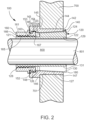
- the coupling device 100 may be configured to couple a hub component 700 with a shaft component 800.
- the coupling device 100 may be configured to apply a radial force to the shaft component 800 as well as configured to apply a radial force to the hub component 700 coupling the hub component 700 to the shaft component 800.
- an exemplary embodiment of the coupling device 100 comprises an inner element 120, an outer element 140, and a positioning/retaining element 160 (e.g., a nut, a bolt, a screw, or any type of mechanical fastener, and the like, etc.).
- the coupling device 100 further comprises a liner 180 disposed between the inner element 120 and the outer element 140.
- the inner element 120 may comprise a hollow main body having a first end 121 and a second end 122.
- the inner element 120 may be configured to at least partially fit within the outer element 140.
- the inner element 120 may include a first portion 123 and a second portion 124.
- a shoulder 125 may be formed at a juncture of the first portion 123 and the second portion 124.
- the first portion 123 may be configured to cooperate with the positioning/retaining element 160 to cause relative movement therebetween and the second portion 124 may be configured to cooperate with the outer element 140 to couple the components 700, 800 together.
- the first portion 123 may have a generally uniform outer surface 126 having a substantially constant outer diameter and the second portion 124 has a generally inclined outer surface 127 having an outer diameter that gradually increases from adjacent the first portion 123 of the inner element 120 to the second end 122 thereof.
- the second portion 124 of the inner element 120 has a generally frustoconical cross-sectional shape.
- An inner surface 129 of the inner element 120 may be configured to engage the shaft component 800.
- a shape, size, and configuration of the inner surface 129 may correspond with an outer surface 801 of the shaft component 800.
- the inner element 120 may have a corresponding irregular inner surface 129 (e.g., inclined or frustoconical).
- the inner surface 129 of the inner element 120 may also be cylindrical with an inner diameter corresponding to an outer diameter of the shaft component 800.
- the inner diameter of the inner element 120 may be slightly larger than the outer diameter of the shaft component 800 to allow for free sliding movement both axially and radially along the shaft component 800 prior to actuation of the coupling device 100.
- the inner element 120 may be configured to engage the shaft component 800 by contraction so that the inner element 120 grips the shaft component 800 via frictional forces.
- the inner element 120 may comprise a plurality of segments 130 defined by one or more dividers 131 (e.g., slots, grooves, and the like) formed longitudinally or axially in the outer surface 126 and/or the outer surface 127 and/or the inner surface 129 of the inner element 120.
- the dividers 131 are configured to allow radial deflection of the inner element 120 as the coupling device 100 is engaged and/or disengaged.
- the dividers 131 may extend at least partially through only the second portion 124 of the inner element 120, thereby the first portion 123 remains continuous. A number as well as the length, width, and/or spacing of the dividers 131 may be varied to provide a desired flexibility of the inner element 120 for a specific application.
- the outer element 140 may comprise a hollow main body having a first end 141 and a second end 142.
- the outer element 140 may be configured to at least partially surround the inner element 120.
- the outer element 140 may include a first portion 143 and a second portion 144.
- a shoulder 145 may be formed at a juncture of the first portion 143 and the second portion 144.
- the first portion 143 may be configured to cooperate with the positioning/retaining element 160 to cause relative movement of the outer element 140, and the second portion 144 may be configured to cooperate with the inner element 120 to couple the components 700, 800 together.
- the first portion 143 may have a generally uniform outer surface 146 having a substantially constant outer diameter and the second portion 144 may also have a generally uniform outer surface 127 having an substantially constant outer diameter.
- the outer diameter of the first portion 143 is greater than the outer diameter of the second portion 144, which in turn forms the shoulder 145.
- the outer element 140 may be configured to engage the hub component 700 by expansion so that the outer element 140 grips the hub component 700 via frictional forces.
- the outer element 140 may comprise a plurality of segments 150 defined by one or more dividers 151 (e.g., slots, grooves, and the like) formed longitudinally or axially in the outer surface 147 and/or inner surface 148 of the outer element 140.
- the dividers 151 are configured to allow radial deflection of the outer element 140 as the coupling device 100 is engaged and/or disengaged.
- the dividers 151 may extend at least partially through the first portion 143 and/or the second portion 144 of the outer element 140. A number as well as the length, width, and/or spacing of the dividers 151 may be varied to provide a desired flexibility of the outer element 140 for a specific application.
- the outer surface 147 of the outer element 140 may be configured to correspond with an inner surface 701 of the hub component 700.
- the outer element 140 may have a corresponding irregular outer surface 147 (e.g., inclined or frustoconical).
- the outer surface 147 of the outer element 140 may also be cylindrical with an outer diameter corresponding to an inner diameter of the hub component 700.
- the outer diameter of the outer element 140 may be slightly smaller than the inner diameter of the hub component 700 to allow for free sliding movement both axially and radially along the hub component 700 prior to actuation of the coupling device 100.
- the inner element 120 and outer element 140 have reciprocally inclined outer and inner surfaces 127, 152, respectively.
- the inner and outer elements 120, 140 may be configured so that displacement of the outer element 140 relative to the inner element 120 imparts greater radial force than axial force. Accordingly, the forces created by the reciprocally inclined outer and inner surfaces 127, 152 cause greater radial forces than axial forces.
- an engagement e.g., a rotation in a first direction
- an engagement of the positioning/retaining element 160 causes the inner element 120 to be urged radially inward onto the shaft component 800 with sufficient force to impede axial displacement of the inner element 120 relative to the shaft component 800 and the outer element 140 to be urged radially outward onto the hub component 700 with sufficient force to impede axial displacement of the outer element 140 relative to the hub component 700.
- the outer element 140 further includes an interlock 152 for connecting the outer element 140 with the positioning/retaining element 160.
- the interlock 152 of the outer element 140 may be configured to connect the outer element 140 to the positioning/retaining element 160 so as to allow the positioning/retaining element 160 to rotate relative to the outer element 140 while substantially impeding axial movement of the outer element 140 relative to the positioning/retaining element 120.
- the interlock 152 may comprise a circumferential flange 153 that extends around a circumference of the outer element 140, projecting radially inward.
- the interlock may comprise a circumferential groove 154 that extends around the circumference of the outer element 140 adjacent the circumferential flange 153.
- the positioning/retaining element 160 may have an inner diameter that may be larger than the outer diameter of the shaft component 800. Additionally, the outer diameter of the positioning/retaining element 160 may be larger than the outer diameter of the inner element 120. As discussed above, the positioning/retaining element 160 may be connected to the outer element 140 in a manner that substantially impedes axial displacement of the inner element 120 relative to the positioning/retaining element 160. In certain instances, an inner surface 164 of the positioning/retaining element 160 may include a plurality of internal features 165 (e.g., threads, teeth, and the like) formed thereon. The internal features 165 of the positioning/retaining element 160 may be configured to cooperate with the external features 128 of the inner element 120 to cause relative movement therebetween. The internal features 165 may extend from a first end 166 of the positioning/retaining element 160 to ta second end 167 thereof.
- the coupling device 100 further includes a liner 180 for minimizing friction between the outer surface 127 of the inner element 120 and the inner surface 148 of the outer element 140.
- the liner 180 is produced from an anti-friction fabric.
- the liner 180 may be directly applied to the inner surface 148 of the outer element 140. Additionally, or alternatively, the liner 180 may directly applied to the outer surface 127 of the inner element 120.
- the liner 180 may be produced from a woven material coated with a reinforcing thermoset resin.
- the woven material may include PTFE fibers, aramid fiber, carbon fiber, other comparable fibers, and combinations thereof.
- the liner 180 may further comprise an additional performance coating comprised of PTFE.
- the liner 180 may further include a resin layer for self-lubrication.
- the resin layer may comprise PTFE.
- the liner 180 may be a Fenlon TM liner fabric such as Fenlon TM Asta, or Fenlon TM Low Friction Solid Lubricants.
- the various embodiments of the liner 180 described herein are configured to reduce a coefficient of friction (CoF) between the outer surface 127 of the inner element 120 and the inner surface 148 of the outer element 140 of the coupling device 100.
- CoF coefficient of friction
- Minimizing a frictional loss between the surfaces 127, 148 results in a generation of increased radial forces.
- Minimizing the frictional loss results in the coupling device 100 being easier to install, requiring less torque and/or less time. Additionally, the reduction in frictional loss in the coupling device 100 increases a performance thereof.
- the coupling device 100 may further comprise an additional spacer or sleeve configured to cooperate with the outer surface 147 of the outer element 140.
- the spacer or sleeve may be the positioning sleeve described in U.S. Patent No. 9,618,051 .
- the positioning/retaining element 160 is rotated in the first direction causing relative movement between the positioning/retaining element 160 and the inner element 140 via cooperation of the features 128, 165 and applying an axial force on the outer element 140 via the interlock 152.
- the reciprocal inclined surfaces 127, 148 of the inner and outer elements 120, 140, respectively, result in opposing radial forces.
- the inner element 120 contracts to apply a radially inward force on the shaft component 800 and the outer element 140 expands to apply a radially outward force on the hub component 700, thereby coupling the components 700, 800 together.
- the interlock 152 cooperates with the positioning/retaining element 160 to connect the outer element 140 to the positioning/retaining element 160 so as to allow the positioning/retaining element 160 to rotate relative to the outer element 140 and relative axial movement between the inner element 120 and the outer element 140, while substantially impeding axial movement of the outer element 140 relative to the positioning/retaining element 160.
- the coupling device 200 may be employed to couple together a plurality components.
- the coupling device 200 may be configured to couple stationary components together.
- the coupling device 200 may be employed to couple a first stationary component (e.g., a working component) to a second stationary component (e.g., mounting structure or component).
- the coupling device 200 may be configured to couple movable components so that the components move together.
- the coupling device 200 may be used to couple rotatable components so that they rotate together.
- the coupling device 200 may be configured to couple one or more moveable components to one or more stationary components.
- the coupling device 200 may be configured to couple a hub component 700 with a shaft component 800.
- the coupling device 200 may be configured to apply a radial force to the shaft component 800 as well as configured to apply a radial force to the hub component 700 coupling the hub component 700 to the shaft component 800.
- the outer element 240 may be configured to engage the hub component 700 by expansion so that the outer element 240 grips the hub component 700 via frictional forces.
- the outer element 240 may comprise one or more segments 250 defined by one or more dividers 251 (e.g., slots, grooves, and the like) formed longitudinally or axially in an outer surface 247 and/or an inner surface 248 of the outer element 240.
- the dividers 251 are configured to allow radial deflection of the outer element 240 as the coupling device 200 is engaged and/or disengaged.
- the dividers 251 may extend at least partially through the outer element 240. A number as well as the length, width, and/or spacing of the dividers 251 may be varied to provide a desired flexibility of the outer element 240 for a specific application.
- the outer surface 247 of the outer element 240 may be configured to correspond with an inner surface 701 of the hub component 700.
- the outer element 240 may have a corresponding irregular outer surface 247 (e.g., inclined or frustoconical).
- the outer surface 247 of the outer element 240 may also be cylindrical with an outer diameter corresponding to an inner diameter of the hub component 700.
- the outer diameter of the outer element 240 may be slightly smaller than the inner diameter of the hub component 700 to allow for free sliding movement both axially and radially along the hub component 700 prior to actuation or engagement of the coupling device 200.
- an engagement e.g., a rotation in a first direction
- an engagement of the positioning/retaining elements 260 causes the inner element 220 to be urged radially inward onto the shaft component 800 with sufficient force to impede axial displacement of the inner element 220 relative to the shaft component 800 and the outer element 240 to be urged radially outward onto the hub component 700 with sufficient force to impede axial displacement of the outer element 240 relative to the hub component 700.
- the coupling device 200 further includes a liner 280 for minimizing friction between the outer surface 225 of the inner element 220 and the inner surface 248 of the outer element 240.
- the liner 280 is produced from an anti-friction fabric.
- the liner 280 may be directly applied to the inner surface 248 of the outer element 240.
- the liner 280 may directly applied to the outer surface 225 of the inner element 220.
- the liner 280 may be produced from a woven material coated with a reinforcing thermoset resin.
- the woven material may include PTFE fibers, aramid fiber, carbon fiber, other comparable fibers, and combinations thereof.
- the liner 180 may further comprise an additional performance coating comprised of PTFE.
- the liner 180 may further include a resin layer for self-lubrication.
- the resin layer may comprise PTFE.
- the liner 180 may be a Fenlon TM liner fabric such as Fenlon TM Asta, or Fenlon TM Low Friction Solid Lubricants.
- the various embodiments of the liner 280 described herein are configured to reduce a coefficient of friction (CoF) between the outer surface 225 of the inner element 220 and the inner surface 248 of the outer element 240 of the coupling device 200.
- CoF coefficient of friction
- Minimizing a frictional loss between the surfaces 225, 248 results in a generation of increased radial forces.
- Minimizing the frictional loss results in the coupling device 200 being easier to install, requiring less torque and/or less time. Additionally, the reduction in frictional loss in the coupling device 200 increases a performance thereof.
- the coupling device 200 may further comprise an additional spacer or sleeve configured to cooperate with the outer surface 247 of the outer element 240.
- the spacer or sleeve may be the positioning sleeve described in U.S. Patent No. 9,618,051 .
- the coupling device 300 may be employed to couple together a plurality components.
- the coupling device 300 may be configured to couple stationary components together.
- the coupling device 300 may be employed to couple a first stationary component (e.g., a working component) to a second stationary component (e.g., mounting structure or component).
- the coupling device 300 may be configured to couple movable components so that the components move together.
- the coupling device 300 may be used to couple rotatable components so that they rotate together.
- the coupling device 300 may be configured to couple one or more moveable components to one or more stationary components.
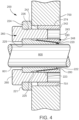
- an exemplary embodiment of the coupling device 300 comprises an inner element 320, an outer element 340, and one or more positioning/retaining elements 360 (e.g., a nut, a bolt, a screw, or any type of mechanical fastener, and the like, etc.).
- the inner element 320 may be configured to at least partially fit within the outer element 340.
- the coupling device 300 further comprises a liner 380 disposed between the inner element 320 and the outer element 340.
- the inner element 320 comprises a first portion 321 and a second portion 322.
- each of the portions 321, 322 has a generally inclined outer surface 325, 326, respectively, having an outer diameter that gradually decreases from outer faces 327, 328 of the portions 321, 322 to respective inner faces 329, 330 thereof. Accordingly, each of the portions 321, 322 of the inner element 320 has a generally frustoconical cross-sectional shape. In some embodiments, each of the portions 321, 322 may be an annular ring.
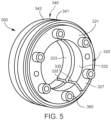
- the portions 321, 322 may each include one or more apertures 331 formed therein.
- the apertures 331 are formed in a radial array configuration.
- Each of the apertures 331 may be configured to receive a respective one of the positioning/retaining elements 360 therein. It is understood that more or less apertures 331 than shown may be formed in the portions 321, 322 as desired.
- an inner surface 334 of the apertures 331 may include a plurality of internal features (e.g., threads, teeth, and the like) formed thereon.
- the internal features may be configured to cooperate with the positioning/retaining element 360 to cause relative movement therebetween and/or relative movement between the inner and outer elements 320, 340 to couple the components 700, 800 together. It should be appreciated that various other means and methods of causing relative movement between the elements 320, 340 and/or the positioning/retaining element 360 may be employed if desired.
- Inner surfaces 332, 333 of the portions 321, 322, respectively, may be configured to engage the shaft component 800.
- a shape, size, and configuration of the inner surfaces 332, 333 may correspond with an outer surface 801 of the shaft component 800.
- the shaft component 800 has an irregular outer surface 801 (e.g., inclined or frustoconical)
- at least one of the portions 321, 322 may have a corresponding irregular inner surface 332, 333 (e.g., inclined or frustoconical).
- the inner surfaces 332, 333 of the portions 321, 322 may also be cylindrical with inner diameters corresponding to an outer diameter of the shaft component 800.
- the inner diameters of the portions 321, 322 may be slightly larger than the outer diameter of the shaft component 800 to allow for free sliding movement both axially and radially along the shaft component 800 prior to actuation or engagement of the coupling device 300.
- the portions 321, 322 of the inner element 320 may be configured to engage the shaft component 800 by contraction so that the portions 321, 322 grip the shaft component 800 via frictional forces.
- at least one of the portions 321, 322 of the inner element 320 may comprise a plurality of segments defined by one or more dividers 335 (e.g., slots, grooves, and the like) formed axially in the inner surfaces 332, 333 and/or the outer surfaces 325, 326 of the portions 321, 322.
- the dividers 335 are configured to allow radial deflection of the inner element 320 as the coupling device 300 is engaged and/or disengaged.
- the dividers 335 may extend at least partially through the inner element 320. A number as well as the length, width, and/or spacing of the dividers 335 may be varied to provide a desired flexibility of the inner element 320 for a specific application.
- the outer element 340 comprises a first portion 341 and a second portion 342.
- Each of the portions 341, 342 has a generally inclined inner surface 347, 348, respectively, having an inner diameter that gradually decreases from outer faces 356, 357 of the portions 321, 322 to respective inner faces 358, 359 thereof.
- each of the portions 341, 342 of the outer element 340 has a generally frustoconical cross-sectional shape.
- each of the portions 341, 342 may be an annular ring.
- the portions 341, 342 of the outer element 340 may be configured to engage the hub component 700 by expansion so that the outer element 340 grips the hub component 700 via frictional forces.
- one or more of the portions 341, 342 of the outer element 340 may comprise one or more segments defined by one or more dividers (e.g., slots, grooves, and the like) formed longitudinally or axially in respective outer surfaces 343, 344 and/or inner surfaces 347, 348 of the portions 341, 342 of the outer element 340.
- the dividers are configured to allow radial deflection of the outer element 340 as the coupling device 300 is engaged and/or disengaged.
- the dividers may extend at least partially through the outer element 340. A number as well as the length, width, and/or spacing of the dividers may be varied to provide a desired flexibility of the outer element 340 for a specific application.
- Engaging surfaces 349, 350 of the portions 341, 342 of the outer element 340 may be configured to correspond with an engaging surface 701 of the hub component 700.
- the hub component 700 has an irregular engaging surface 701 (e.g., inclined or frustoconical)
- the outer element 340 may have at least one corresponding irregular engaging surface 349, 350 (e.g., inclined or frustoconical).
- the hub component 700 is cylindrical
- at least one of the engaging surfaces 349, 350 of the respective portions 341, 342 of the outer element 340 may also be cylindrical.
- the diameter of the engaging surfaces 349, 350 of the portions 341, 342 may be slightly larger than the outer diameter of the hub component 700 to allow for free sliding movement along the hub component 700 prior to actuation or engagement of the coupling device 300.
- the portions 321, 322 of the inner element 320 and the portions 341, 342 of the outer element 340 have reciprocally inclined outer surfaces 325, 326 and inner surfaces 347, 348, respectively.
- the inner and outer elements 320, 340 may be configured so that displacement of the outer element 340 relative to the inner element 320 imparts greater radial force than axial force. Accordingly, the forces created by the reciprocally inclined surfaces 325, 326, 347, 348 cause greater radial forces than axial forces.
- an engagement e.g., a rotation in a first direction
- an engagement of the positioning/retaining elements 360 causes the inner element 320 to be urged radially inward onto the shaft component 800 with sufficient force to impede axial displacement of the inner element 320 relative to the shaft component 800 and the outer element 340 to be urged radially outward onto the hub component 700 with sufficient force to impede axial displacement of the outer element 340 relative to the hub component 700.
- each of the positioning/retaining elements 360 may include a plurality of external features (e.g., threads, teeth, and the like) formed thereon.
- the external features of the portioning/retaining element 360 may be configured to cooperate with the internal features of the inner element 340 to cause relative movement therebetween and/or between the portions 341, 342 of the outer element 340 and the portions 321, 322 of the inner element 320.
- one or more of the portions 381, 382 of the liner 280 may be directly applied to the inner surfaces 347, 348 of the outer element 340. Additionally, or alternatively, one or more of the portions 381, 382 of the liner 380 may directly applied to the outer surfaces 325, 326 of the inner element 320. In some embodiments, one or more of the portions 381, 382 of the liner 380 may be produced from a woven material coated with a reinforcing thermoset resin. The woven material may include PTFE fibers, aramid fiber, carbon fiber, other comparable fibers, and combinations thereof. In some embodiments, one or more of the portions 381, 382 of the liner 380 may further comprise an additional performance coating comprised of PTFE.
- one or more of the portions 381, 382 of the liner 380 may further include a resin layer for self-lubrication.
- the resin layer may comprise PTFE.
- one or more of the portions 381, 382 of the liner 380 may be a Fenlon TM liner fabric such as Fenlon TM Asta, or Fenlon TM Low Friction Solid Lubricants.
- the positioning/retaining elements 360 are rotated in the first direction causing relative movement between the positioning/retaining element 360 and the portions 321, 322 of the inner element 320 via cooperation of the external and internal features thereof and applying an axial force on the inner element 320.
- the portions 321, 322 of the inner element 320 are drawn closer together as the positioning/retaining elements 360 are rotated in the first direction.
- the positioning/retaining elements 360 are rotated in an opposite second direction causing relative movement between the positioning/retaining element 360 and the portions 321, 322 of the inner element 320 via cooperation of the external and internal features thereof and releasing both the axial force on the portions 321, 322 of the inner element 320 and the opposing radial forces caused by the reciprocal inclined surfaces 325, 326, 347, 348 of the inner and outer elements 320, 340, respectively.
- the coupling device 400 may be employed to couple together a plurality components.
- the coupling device 400 may be configured to couple stationary components together.
- the coupling device 400 may be employed to couple a first stationary component (e.g., a working component) to a second stationary component (e.g., mounting structure or component).
- the coupling device 400 may be configured to couple movable components so that the components move together.
- the coupling device 400 may be used to couple rotatable components so that they rotate together.
- the coupling device 400 may be configured to couple one or more moveable components to one or more stationary components.
- the coupling device 400 may be configured to couple a hub component 700 with a shaft component 800.
- the coupling device 400 may be configured to apply a radial force to the hub component 700 and/or the shaft component 800 coupling the hub component 700 to the shaft component 800.
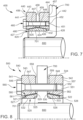
- An exemplary embodiment of the coupling device 400 comprises an inner element 420, an outer element 440, and one or more positioning/retaining elements 460 (e.g., a nut, a bolt, a screw, or any type of mechanical fastener, and the like, etc.).
- the inner element 420 may be configured to at least partially fit within the outer element 440.
- the coupling device 400 further comprises a liner 480 disposed between the inner element 420 and the outer element 440.
- the inner element 420 has generally inclined outer surface 425, 426 that form an apex 424.
- An outer diameter of the inner element 420 gradually increases from outer faces 427, 428 of the inner element 420 to the apex 424 thereof.
- the inner element 420 may be an annular ring.
- An inner surface 432 of the inner element 420 may be configured to engage the hub component 700.
- a shape, size, and configuration of the inner surface 432 may correspond with an outer surface 701 of the hub component 700.
- the inner element 420 may have a corresponding irregular inner surface 432 (e.g., inclined or frustoconical).
- the inner surface 432 of the inner element 420 may also be cylindrical with an inner diameter corresponding to an outer diameter of the hub component 700.
- the inner diameter of the inner element 420 may be slightly larger than the outer diameter of the hub component 700 to allow for free sliding movement both axially and radially along the hub component 700 prior to actuation or engagement of the coupling device 400.
- the inner element 420 may be configured to engage the hub component 700 by contraction so that the inner element 420 grips the hub component 700 via frictional forces.
- the inner element 420 may comprise a plurality of segments defined by one or more dividers (e.g., slots, grooves, and the like) formed axially in the inner surface 432 and/or the outer surfaces 425, 426.
- the dividers may be configured to allow radial deflection of the inner element 420 as the coupling device 400 is engaged and/or disengaged.
- the dividers may extend at least partially through the inner element 420. A number as well as the length, width, and/or spacing of the dividers may be varied to provide a desired flexibility of the inner element 420 for a specific application.
- an inner surface 452 of the apertures 451 may include a plurality of internal features (e.g., threads, teeth, and the like) formed thereon.
- the internal features may be configured to cooperate with the positioning/retaining element 460 to cause relative movement therebetween and/or relative movement between the inner and outer elements 420, 440 to couple the components 700, 800 together. It should be appreciated that various other means and methods of causing relative movement between the elements 420, 440 and/or the positioning/retaining element 460 may be employed if desired.
- Each of the inner surfaces 447, 448 of the portions 441, 442 of the outer element 440 may be configured to engage the inner element 420.
- a shape, size, and configuration of the inner surfaces 447, 448 may correspond with the respective outer surfaces 425, 426 of the inner element 420.
- the outer diameter of the inner element 420 may be slightly smaller than the inner diameter of the outer element 440 to allow for movement of the outer element 440 relative to the inner element 420 during actuation or engagement of the coupling device 400.
- the inner element 420 and the portions 441, 442 of the outer element 440 have reciprocally inclined outer surfaces 425, 426 and inner surfaces 447, 448, respectively.
- the inner and outer elements 420, 440 may be configured so that displacement of the outer element 440 relative to the inner element 420 imparts greater radial force than axial force. Accordingly, the forces created by the reciprocally inclined surfaces 425, 426, 447, 448 cause greater radial forces than axial forces.
- an engagement e.g., a rotation in a first direction
- an engagement of the positioning/retaining elements 460 causes the inner element 420 to be urged radially inward onto the hub component 700 with sufficient force to impede axial displacement of the inner element 420 relative to the hub component 700 and the hub component 700 to be urged radially inward onto the shaft component 800 with sufficient force to impede axial displacement of the hub component 700 relative to the shaft component 800.
- the coupling device 500 may be configured to couple a hub component 700 with a shaft component 800.
- the coupling device 400 may be configured to apply a radial force to the hub component 700 and/or the shaft component 800 coupling the hub component 700 to the shaft component 800.
- the dividers may only extend at least partially through one or more of the portions 521, 522 of the inner element 520.
- a number as well as the length, width, and/or spacing of the dividers may be varied to provide a desired flexibility of the inner element 520 for a specific application.
- an inner surface 552 of the apertures 551 may include a plurality of internal features (e.g., threads, teeth, and the like) formed thereon.
- the internal features may be configured to cooperate with the positioning/retaining element 560 to cause relative movement therebetween and/or relative movement between the inner and outer elements 520, 540 to couple the components 700, 800 together. It should be appreciated that various other means and methods of causing relative movement between the elements 520, 540 and/or the positioning/retaining element 560 may be employed if desired.
- the portions 541, 542 of the outer element 540 may be configured to engage the inner element 520 by contraction so that the outer element 540 grips the inner element 520 via frictional forces.
- one or more of the portions 541, 542 of the outer element 540 may comprise one or more segments defined by one or more dividers (e.g., slots, grooves, and the like) formed longitudinally or axially in respective outer surfaces 543, 544 and/or inner surfaces 547, 548 of the portions 541, 542 of the outer element 540.
- the dividers may be configured to allow radial deflection of the outer element 540 as the coupling device 500 is engaged and/or disengaged.
- the dividers may extend at least partially through the outer element 540. A number as well as the length, width, and/or spacing of the dividers may be varied to provide a desired flexibility of the outer element 540 for a specific application.
- Each of the inner surfaces 547, 548 of the portions 541, 542 of the outer element 540 may be configured to engage the inner element 520.
- a shape, size, and configuration of the inner surfaces 547, 548 may correspond with the respective outer surfaces 525, 526 of the inner element 520.
- the outer diameter of the inner element 520 may be slightly smaller than the inner diameter of the outer element 540 to allow for movement of the outer element 540 relative to the inner element 520 during actuation or engagement of the coupling device 500.
- the inner element 520 and the portions 541, 542 of the outer element 540 have reciprocally inclined outer surfaces 525, 526 and inner surfaces 547, 548, respectively.
- the inner and outer elements 520, 540 may be configured so that displacement of the outer element 540 relative to the inner element 520 imparts greater radial force than axial force. Accordingly, the forces created by the reciprocally inclined surfaces 525, 526, 547, 548 cause greater radial forces than axial forces.
- an engagement e.g., a rotation in a first direction
- an engagement of the positioning/retaining elements 560 causes the inner element 520 to be urged radially inward onto the hub component 700 with sufficient force to impede axial displacement of the inner element 520 relative to the hub component 700 and the hub component 700 to be urged radially inward onto the shaft component 800 with sufficient force to impede axial displacement of the hub component 700 relative to the shaft component 800.
- each of the positioning/retaining elements 560 may be connected to the outer element 520.
- each of the positioning/retaining elements 560 may include a plurality of external features (e.g., threads, teeth, and the like) formed thereon.
- the external features of the portioning/retaining 560 may be configured to cooperate with the internal features of the apertures 551 of the outer element 540 to cause relative movement therebetween and/or between the portions 541, 542 of the outer element 540 and the inner element 520.
- the coupling device 500 further includes a liner 580 for minimizing friction between the outer surfaces 525, 526 of the inner element 520 and the inner surfaces 547, 548 of the portions 541, 542 of the outer element 540.
- the liner 580 may be a single unitary structure or be comprised of a plurality of separate portions.
- the liner 580 is produced from an anti-friction fabric.
- the liner 580 may be directly applied to the inner surfaces 547, 548 of the outer element 540. Additionally, or alternatively, the liner 580 may directly applied to the outer surfaces 525, 526 of the inner element 520.
- the positioning/retaining elements 560 are rotated in the first direction causing relative movement between the positioning/retaining element 560 and the portions 541, 542 of the outer element 520 via cooperation of the external and internal features thereof and applying an axial force on the outer element 520.
- the portions 541, 542 of the outer element 520 are drawn closer together causing a compression of the inner element 520.
- the portions 541, 542 of the inner element 520 contract to apply a radially inward force on the hub component 700 and the shaft component 800, thereby coupling the components 700, 800 together.
- FIG. 9 illustrates a coupling device 600 according to another embodiment of the present disclosure is illustrated.
- the coupling device 600 may be employed to couple together a plurality components.
- the coupling device 600 may be configured to couple stationary components together.
- the coupling device 600 may be employed to couple a first stationary component (e.g., a working component) to a second stationary component (e.g., mounting structure or component).
- the coupling device 600 may be configured to couple movable components so that the components move together.
- the coupling device 600 may be used to couple rotatable components so that they rotate together.
- the coupling device 600 may be configured to couple one or more moveable components to one or more stationary components.
- An exemplary embodiment of the coupling device 600 comprises an inner element 620, an outer element 640, and one or more positioning/retaining elements 660 (e.g., a nut, a bolt, a screw, or any type of mechanical fastener, and the like, etc.).
- the inner element 620 may be configured to at least partially fit within the outer element 640.
- the coupling device 600 further comprises a liner 680 disposed between the inner element 620 and the outer element 640.
- the inner element 620 has a generally inclined outer surface 625 having an outer diameter that gradually increases from an outer faces 627 to an inner face 629 thereof. Accordingly, the inner element 620 has a generally frustoconical cross-sectional shape.
- the inner element 620 may be an annular ring.
- An inner surface 632 of the inner element 620 may be configured to engage the hub component 700.
- a shape, size, and configuration of the inner surface 632 may correspond with an outer surface 701 of the hub component 700.
- the inner element 620 may have a corresponding irregular inner surface 632 (e.g., inclined or frustoconical).
- the inner surface 632 of the inner element 620 may also be cylindrical with an inner diameter corresponding to an outer diameter of the hub component 700.
- the inner diameter of the inner element 620 may be slightly larger than the outer diameter of the hub component 700 to allow for free sliding movement both axially and radially along the hub component 700 prior to actuation or engagement of the coupling device 600.
- the outer element 640 may be configured to engage the inner element 620 by contraction so that the outer element 640 grips the inner element 620 via frictional forces.
- the outer element 640 may comprise one or more segments defined by one or more dividers (e.g., slots, grooves, and the like) formed longitudinally or axially in an outer surface 643 and/or an inner surface 647 of the outer element 640.
- the dividers may be configured to allow radial deflection of the outer element 640 as the coupling device 600 is engaged and/or disengaged.
- the dividers may extend at least partially through the outer element 640. A number as well as the length, width, and/or spacing of the dividers may be varied to provide a desired flexibility of the outer element 640 for a specific application.
- the inner surface 647 of the outer element 640 may be configured to engage the inner element 620.
- a shape, size, and configuration of the inner surfaces 647 may correspond with the outer surface 625 of the inner element 620.
- the outer diameter of the inner element 620 may be slightly smaller than the inner diameter of the outer element 640 to allow for movement of the outer element 640 relative to the inner element 620 during actuation or engagement of the coupling device 600.
- the inner element 620 and the outer element 640 have reciprocally inclined outer surface 625 and inner surface 647, respectively.
- the inner and outer elements 620, 640 may be configured so that displacement of the outer element 640 relative to the inner element 620 imparts greater radial force than axial force. Accordingly, the forces created by the reciprocally inclined surfaces 625, 647 cause greater radial forces than axial forces.
- an engagement e.g., a rotation in a first direction
- an engagement of the positioning/retaining elements 660 causes the inner element 620 to be urged radially inward onto the hub component 700 with sufficient force to impede axial displacement of the inner element 620 relative to the hub component 700 and the hub component 700 to be urged radially inward onto the shaft component 800 with sufficient force to impede axial displacement of the hub component 700 relative to the shaft component 800.
- the coupling device 600 further includes a liner 680 for minimizing friction between the outer surface 625 of the inner element 620 and the inner surface 647 of the outer element 640.
- the liner 680 may be a single unitary structure or be comprised of a plurality of separate portions.
- the liner 680 is produced from an anti-friction fabric.
- the liner 680 may be directly applied to the inner surface 647 of the outer element 640. Additionally, or alternatively, the liner 680 may directly applied to the outer surface 625 of the inner element 620.
- the liner 680 may be produced from a woven material coated with a reinforcing thermoset resin.
- the various embodiments of the liner 680 described herein are configured to reduce a coefficient of friction (CoF) between the outer surface 625 of the inner element 620 and the inner surface 647 of the outer element 640 of the coupling device 600.
- CoF coefficient of friction
- Minimizing a frictional loss between the surfaces 625, 647 results in a generation of increased radial forces.
- Minimizing the frictional loss results in the coupling device 600 being easier to install, requiring less torque and/or less time. Additionally, the reduction in frictional loss in the coupling device 600 increases a performance thereof.
- the coupling devices 100, 200, 300, 400, 500, 600 described herein are an abbreviated list of applicable embodiments. It is understood that the coupling devices 100, 200, 300, 400, 500, 600 may be keyless locking devices.
- the CoF rating of the coupling devices 100, 200, 300, 400, 500, 600 is about 0.02.
- the scope of the invention is intended to include any device that utilizes tapered surfaces in combination with a liner comprising an anti-friction fabric as defined in claim 1.
Landscapes
- Engineering & Computer Science (AREA)
- General Engineering & Computer Science (AREA)
- Mechanical Engineering (AREA)
- Mutual Connection Of Rods And Tubes (AREA)
Claims (13)
- Vorrichtung (100) zum Verbinden von Komponenten, umfassend:ein erstes Element (120, 140) mit mindestens einer Schrägfläche; undein zweites Element (120, 140) mit mindestens einer zu der mindestens einen Schrägfläche des ersten Elements reziproken Schrägfläche, wobei eine axiale Bewegung von mindestens einem der Elemente bewirkt, dass eine radiale Kraft auf mindestens eine der Komponenten ausgeübt wird, gekennzeichnet durch einen Einsatz (180), der zwischen der mindestens einen Schrägfläche des ersten Elements und der mindestens einen Schrägfläche des zweiten Elements angeordnet ist, wobei der Einsatz ein Gleitgewebe ist.
- Vorrichtung nach Anspruch 1, ferner umfassend ein Positionierungs-/Halteelement (160), das dazu ausgestaltet ist, mit mindestens einem von dem ersten Element und dem zweiten Element zusammenzuwirken.
- Vorrichtung nach Anspruch 2, wobei sich das Positionierungs-/Halteelement in einem Gewindeeingriff mit mindestens einem von dem ersten Element und dem zweiten Element befindet.
- Vorrichtung nach Anspruch 2, wobei das Positionierungs-/Halteelement mit dem zweiten Element durch eine Verriegelungsverbindung (152) verbunden ist.
- Vorrichtung nach Anspruch 2, wobei das Positionierungs-/Halteelement eines von einer Mutter, einem Bolzen, einer Schraube und einem mechanischen Befestigungselement ist.
- Vorrichtung nach Anspruch 2, wobei das Positionierungs-/Halteelement zumindest teilweise in einer der Komponenten aufgenommen ist.
- Vorrichtung nach Anspruch 2, wobei das Positionierungs-/Halteelement derart ausgestaltet ist, dass es die axiale Bewegung des mindestens einen von dem ersten Element und dem zweiten Element bewirkt.
- Vorrichtung nach Anspruch 1, wobei das erste Element einen ersten Abschnitt (321) und einen zweiten Abschnitt (322) umfasst,
wobei mindestens einer von dem ersten Abschnitt und dem zweiten Abschnitt die mindestens eine Schrägfläche umfasst. - Vorrichtung nach Anspruch 1, wobei das zweite Element einen ersten Abschnitt und einen zweiten Abschnitt umfasst, wobei mindestens einer von dem ersten Abschnitt und dem zweiten Abschnitt die mindestens eine Schrägfläche umfasst.
- Vorrichtung nach Anspruch 1, wobei mindestens eines von dem ersten Element und dem zweiten Element eine oder mehr darin ausgebildete Öffnungen (331) umfasst.
- Vorrichtung nach Anspruch 1, wobei mindestens eines von dem ersten Element und dem zweiten Element eine oder mehr darin ausgebildete Trennwände umfasst.
- Vorrichtung nach Anspruch 1, wobei mindestens eines von dem ersten Element und dem zweiten Element ein ringförmiger Ring ist.
- Vorrichtung nach Anspruch 1, wobei ein Reibungskoeffizient der Vorrichtung ungefähr 0,02 beträgt.
Applications Claiming Priority (1)
| Application Number | Priority Date | Filing Date | Title |
|---|---|---|---|
| US202263373881P | 2022-08-30 | 2022-08-30 |
Publications (3)
| Publication Number | Publication Date |
|---|---|
| EP4332387A1 EP4332387A1 (de) | 2024-03-06 |
| EP4332387C0 EP4332387C0 (de) | 2025-07-09 |
| EP4332387B1 true EP4332387B1 (de) | 2025-07-09 |
Family
ID=87863398
Family Applications (1)
| Application Number | Title | Priority Date | Filing Date |
|---|---|---|---|
| EP23194297.0A Active EP4332387B1 (de) | 2022-08-30 | 2023-08-30 | Kupplungsvorrichtung mit minimiertem reibungskoeffizient |
Country Status (2)
| Country | Link |
|---|---|
| US (1) | US20240068506A1 (de) |
| EP (1) | EP4332387B1 (de) |
Family Cites Families (21)
| Publication number | Priority date | Publication date | Assignee | Title |
|---|---|---|---|---|
| US2862283A (en) * | 1957-05-28 | 1958-12-02 | Russell Mfg Co | Anti-friction fabric |
| US4345851A (en) * | 1978-07-10 | 1982-08-24 | Harrington Hoists | Mounting device |
| US4202644A (en) * | 1978-07-10 | 1980-05-13 | Trantorque Corporation | Mounting device |
| US4543704A (en) * | 1978-07-10 | 1985-10-01 | Fenner America Inc. | Method for anchoring a machine element coaxially on a rotary shaft |
| US4600334A (en) * | 1978-07-10 | 1986-07-15 | Fenner America Inc. | Mounting device without axial motion |
| US4367053A (en) * | 1978-11-06 | 1983-01-04 | Andrew Stratienko | Clamping device |
| JPS6052424U (ja) * | 1983-05-31 | 1985-04-12 | 株式会社椿本チエイン | 軸と回転体との締結装置 |
| JPS63210418A (ja) * | 1987-02-24 | 1988-09-01 | Tsubakimoto Chain Co | 軸と回転体の締結装置 |
| DE8816656U1 (de) * | 1988-08-06 | 1990-04-19 | Müllenberg, Ralph, 4048 Grevenbroich | Spannsatz mit Schraubmuffe |
| DE3835894C1 (de) * | 1988-10-21 | 1989-08-24 | Ralph 4048 Grevenbroich De Muellenberg | |
| US5374135A (en) * | 1993-08-12 | 1994-12-20 | Moore Business Forms, Inc. | Mounting machine with ready transportability |
| US5474403A (en) * | 1994-03-31 | 1995-12-12 | Fenner, Inc. | Mounting device |
| US5695297A (en) * | 1996-09-11 | 1997-12-09 | Fenner, Inc. | Mounting device |
| AU4750897A (en) * | 1996-10-09 | 1998-05-05 | Fenner, Inc. | Mounting device |
| US6357958B1 (en) * | 1999-12-09 | 2002-03-19 | Fenner, Inc. | Universally adjustable mounting device |
| US6467989B1 (en) * | 2000-06-12 | 2002-10-22 | Michael Finkelstein | Adjustable column connection |
| JP2004286155A (ja) * | 2003-03-24 | 2004-10-14 | Tsubaki Emerson Co | 軸と回転体を締結する摩擦式締結具 |
| US20050089364A1 (en) * | 2003-10-24 | 2005-04-28 | Geib Randall R. | Mounting device |
| US9618051B2 (en) | 2012-12-06 | 2017-04-11 | Fenner U.S., Inc. | Method and apparatus for mounting a machine element onto a shaft |
| US10364847B2 (en) * | 2016-07-20 | 2019-07-30 | Fenner U.S., Inc. | Mounting device |
| SE545825C2 (en) * | 2020-05-13 | 2024-02-13 | Expander System Sweden Ab | An expansion sleeve and a connection device |
-
2023
- 2023-08-30 US US18/458,680 patent/US20240068506A1/en active Pending
- 2023-08-30 EP EP23194297.0A patent/EP4332387B1/de active Active
Also Published As
| Publication number | Publication date |
|---|---|
| US20240068506A1 (en) | 2024-02-29 |
| EP4332387C0 (de) | 2025-07-09 |
| EP4332387A1 (de) | 2024-03-06 |
Similar Documents
| Publication | Publication Date | Title |
|---|---|---|
| US4345851A (en) | Mounting device | |
| EP0007217B1 (de) | Montagevorrichtung | |
| US5474403A (en) | Mounting device | |
| EP2823186B1 (de) | Kupplungsbolzen mit radialer passform und hoher kapazität | |
| EP3133298B1 (de) | Verbinder | |
| KR101779789B1 (ko) | 토크 제한 공차링 | |
| US5740893A (en) | One-way clutch and method of making bearing ring | |
| KR20050086775A (ko) | 트롤리 휘일용 저어널 베어링 | |
| EP3382219B1 (de) | Welle aus faserverstärktem kunststoff | |
| US11466725B2 (en) | Composite shaft | |
| US11525529B2 (en) | Composite tubular structure | |
| EP4332387B1 (de) | Kupplungsvorrichtung mit minimiertem reibungskoeffizient | |
| US12338855B2 (en) | Composite end connections | |
| EP3612440B1 (de) | Einstellbare gelenkanordnung | |
| CN111623104A (zh) | 用于两组件或多组件齿轮的齿圈载体部件以及齿轮 | |
| JP7197388B2 (ja) | クラッチ機構、駆動力伝達機構、およびロボット | |
| EP2222970B1 (de) | Wellen- und flanschkomponente für eine riemenscheibe eines stufenlosen getriebes | |
| CN118234966A (zh) | 特征在于由规则多边形构成的轴体的轴毂连接 | |
| AU2016272434A1 (en) | Gypsy for windlass and method for its manufacture | |
| UA114916C2 (uk) | Торцева пружна муфта |
Legal Events
| Date | Code | Title | Description |
|---|---|---|---|
| PUAI | Public reference made under article 153(3) epc to a published international application that has entered the european phase |
Free format text: ORIGINAL CODE: 0009012 |
|
| STAA | Information on the status of an ep patent application or granted ep patent |
Free format text: STATUS: THE APPLICATION HAS BEEN PUBLISHED |
|
| AK | Designated contracting states |
Kind code of ref document: A1 Designated state(s): AL AT BE BG CH CY CZ DE DK EE ES FI FR GB GR HR HU IE IS IT LI LT LU LV MC ME MK MT NL NO PL PT RO RS SE SI SK SM TR |
|
| STAA | Information on the status of an ep patent application or granted ep patent |
Free format text: STATUS: REQUEST FOR EXAMINATION WAS MADE |
|
| 17P | Request for examination filed |
Effective date: 20240701 |
|
| RBV | Designated contracting states (corrected) |
Designated state(s): AL AT BE BG CH CY CZ DE DK EE ES FI FR GB GR HR HU IE IS IT LI LT LU LV MC ME MK MT NL NO PL PT RO RS SE SI SK SM TR |
|
| GRAP | Despatch of communication of intention to grant a patent |
Free format text: ORIGINAL CODE: EPIDOSNIGR1 |
|
| STAA | Information on the status of an ep patent application or granted ep patent |
Free format text: STATUS: GRANT OF PATENT IS INTENDED |
|
| INTG | Intention to grant announced |
Effective date: 20250211 |
|
| GRAS | Grant fee paid |
Free format text: ORIGINAL CODE: EPIDOSNIGR3 |
|
| GRAA | (expected) grant |
Free format text: ORIGINAL CODE: 0009210 |
|
| STAA | Information on the status of an ep patent application or granted ep patent |
Free format text: STATUS: THE PATENT HAS BEEN GRANTED |
|
| AK | Designated contracting states |
Kind code of ref document: B1 Designated state(s): AL AT BE BG CH CY CZ DE DK EE ES FI FR GB GR HR HU IE IS IT LI LT LU LV MC ME MK MT NL NO PL PT RO RS SE SI SK SM TR |
|
| REG | Reference to a national code |
Ref country code: GB Ref legal event code: FG4D |
|
| REG | Reference to a national code |
Ref country code: CH Ref legal event code: EP |
|
| REG | Reference to a national code |
Ref country code: IE Ref legal event code: FG4D |
|
| U01 | Request for unitary effect filed |
Effective date: 20250709 |
|
| U07 | Unitary effect registered |
Designated state(s): AT BE BG DE DK EE FI FR IT LT LU LV MT NL PT RO SE SI Effective date: 20250715 |
|
| U20 | Renewal fee for the european patent with unitary effect paid |
Year of fee payment: 3 Effective date: 20250811 |