EP4332157A1 - Treatment apparatus, method for preparing degradation product, and treatment method - Google Patents
Treatment apparatus, method for preparing degradation product, and treatment method Download PDFInfo
- Publication number
- EP4332157A1 EP4332157A1 EP22936639.8A EP22936639A EP4332157A1 EP 4332157 A1 EP4332157 A1 EP 4332157A1 EP 22936639 A EP22936639 A EP 22936639A EP 4332157 A1 EP4332157 A1 EP 4332157A1
- Authority
- EP
- European Patent Office
- Prior art keywords
- liquid medium
- electromagnetic wave
- polymer compound
- container
- plasma
- Prior art date
- Legal status (The legal status is an assumption and is not a legal conclusion. Google has not performed a legal analysis and makes no representation as to the accuracy of the status listed.)
- Pending
Links
Images


Classifications
-
- C—CHEMISTRY; METALLURGY
- C07—ORGANIC CHEMISTRY
- C07C—ACYCLIC OR CARBOCYCLIC COMPOUNDS
- C07C67/00—Preparation of carboxylic acid esters
- C07C67/475—Preparation of carboxylic acid esters by splitting of carbon-to-carbon bonds and redistribution, e.g. disproportionation or migration of groups between different molecules
-
- C—CHEMISTRY; METALLURGY
- C08—ORGANIC MACROMOLECULAR COMPOUNDS; THEIR PREPARATION OR CHEMICAL WORKING-UP; COMPOSITIONS BASED THEREON
- C08J—WORKING-UP; GENERAL PROCESSES OF COMPOUNDING; AFTER-TREATMENT NOT COVERED BY SUBCLASSES C08B, C08C, C08F, C08G or C08H
- C08J11/00—Recovery or working-up of waste materials
- C08J11/04—Recovery or working-up of waste materials of polymers
- C08J11/10—Recovery or working-up of waste materials of polymers by chemically breaking down the molecular chains of polymers or breaking of crosslinks, e.g. devulcanisation
- C08J11/18—Recovery or working-up of waste materials of polymers by chemically breaking down the molecular chains of polymers or breaking of crosslinks, e.g. devulcanisation by treatment with organic material
- C08J11/22—Recovery or working-up of waste materials of polymers by chemically breaking down the molecular chains of polymers or breaking of crosslinks, e.g. devulcanisation by treatment with organic material by treatment with organic oxygen-containing compounds
- C08J11/24—Recovery or working-up of waste materials of polymers by chemically breaking down the molecular chains of polymers or breaking of crosslinks, e.g. devulcanisation by treatment with organic material by treatment with organic oxygen-containing compounds containing hydroxyl groups
-
- C—CHEMISTRY; METALLURGY
- C08—ORGANIC MACROMOLECULAR COMPOUNDS; THEIR PREPARATION OR CHEMICAL WORKING-UP; COMPOSITIONS BASED THEREON
- C08J—WORKING-UP; GENERAL PROCESSES OF COMPOUNDING; AFTER-TREATMENT NOT COVERED BY SUBCLASSES C08B, C08C, C08F, C08G or C08H
- C08J11/00—Recovery or working-up of waste materials
- C08J11/04—Recovery or working-up of waste materials of polymers
- C08J11/10—Recovery or working-up of waste materials of polymers by chemically breaking down the molecular chains of polymers or breaking of crosslinks, e.g. devulcanisation
-
- B—PERFORMING OPERATIONS; TRANSPORTING
- B01—PHYSICAL OR CHEMICAL PROCESSES OR APPARATUS IN GENERAL
- B01J—CHEMICAL OR PHYSICAL PROCESSES, e.g. CATALYSIS OR COLLOID CHEMISTRY; THEIR RELEVANT APPARATUS
- B01J19/00—Chemical, physical or physico-chemical processes in general; Their relevant apparatus
- B01J19/08—Processes employing the direct application of electric or wave energy, or particle radiation; Apparatus therefor
- B01J19/087—Processes employing the direct application of electric or wave energy, or particle radiation; Apparatus therefor employing electric or magnetic energy
- B01J19/088—Processes employing the direct application of electric or wave energy, or particle radiation; Apparatus therefor employing electric or magnetic energy giving rise to electric discharges
-
- B—PERFORMING OPERATIONS; TRANSPORTING
- B01—PHYSICAL OR CHEMICAL PROCESSES OR APPARATUS IN GENERAL
- B01J—CHEMICAL OR PHYSICAL PROCESSES, e.g. CATALYSIS OR COLLOID CHEMISTRY; THEIR RELEVANT APPARATUS
- B01J19/00—Chemical, physical or physico-chemical processes in general; Their relevant apparatus
- B01J19/08—Processes employing the direct application of electric or wave energy, or particle radiation; Apparatus therefor
- B01J19/12—Processes employing the direct application of electric or wave energy, or particle radiation; Apparatus therefor employing electromagnetic waves
- B01J19/122—Incoherent waves
- B01J19/126—Microwaves
-
- C—CHEMISTRY; METALLURGY
- C08—ORGANIC MACROMOLECULAR COMPOUNDS; THEIR PREPARATION OR CHEMICAL WORKING-UP; COMPOSITIONS BASED THEREON
- C08J—WORKING-UP; GENERAL PROCESSES OF COMPOUNDING; AFTER-TREATMENT NOT COVERED BY SUBCLASSES C08B, C08C, C08F, C08G or C08H
- C08J11/00—Recovery or working-up of waste materials
- C08J11/04—Recovery or working-up of waste materials of polymers
- C08J11/10—Recovery or working-up of waste materials of polymers by chemically breaking down the molecular chains of polymers or breaking of crosslinks, e.g. devulcanisation
- C08J11/14—Recovery or working-up of waste materials of polymers by chemically breaking down the molecular chains of polymers or breaking of crosslinks, e.g. devulcanisation by treatment with steam or water
-
- C—CHEMISTRY; METALLURGY
- C08—ORGANIC MACROMOLECULAR COMPOUNDS; THEIR PREPARATION OR CHEMICAL WORKING-UP; COMPOSITIONS BASED THEREON
- C08J—WORKING-UP; GENERAL PROCESSES OF COMPOUNDING; AFTER-TREATMENT NOT COVERED BY SUBCLASSES C08B, C08C, C08F, C08G or C08H
- C08J11/00—Recovery or working-up of waste materials
- C08J11/04—Recovery or working-up of waste materials of polymers
- C08J11/10—Recovery or working-up of waste materials of polymers by chemically breaking down the molecular chains of polymers or breaking of crosslinks, e.g. devulcanisation
- C08J11/18—Recovery or working-up of waste materials of polymers by chemically breaking down the molecular chains of polymers or breaking of crosslinks, e.g. devulcanisation by treatment with organic material
- C08J11/22—Recovery or working-up of waste materials of polymers by chemically breaking down the molecular chains of polymers or breaking of crosslinks, e.g. devulcanisation by treatment with organic material by treatment with organic oxygen-containing compounds
-
- H—ELECTRICITY
- H05—ELECTRIC TECHNIQUES NOT OTHERWISE PROVIDED FOR
- H05H—PLASMA TECHNIQUE; PRODUCTION OF ACCELERATED ELECTRICALLY-CHARGED PARTICLES OR OF NEUTRONS; PRODUCTION OR ACCELERATION OF NEUTRAL MOLECULAR OR ATOMIC BEAMS
- H05H1/00—Generating plasma; Handling plasma
- H05H1/24—Generating plasma
- H05H1/247—Generating plasma using discharges in liquid media
-
- B—PERFORMING OPERATIONS; TRANSPORTING
- B01—PHYSICAL OR CHEMICAL PROCESSES OR APPARATUS IN GENERAL
- B01J—CHEMICAL OR PHYSICAL PROCESSES, e.g. CATALYSIS OR COLLOID CHEMISTRY; THEIR RELEVANT APPARATUS
- B01J2219/00—Chemical, physical or physico-chemical processes in general; Their relevant apparatus
- B01J2219/08—Processes employing the direct application of electric or wave energy, or particle radiation; Apparatus therefor
- B01J2219/0803—Processes employing the direct application of electric or wave energy, or particle radiation; Apparatus therefor employing electric or magnetic energy
- B01J2219/0805—Processes employing the direct application of electric or wave energy, or particle radiation; Apparatus therefor employing electric or magnetic energy giving rise to electric discharges
-
- B—PERFORMING OPERATIONS; TRANSPORTING
- B01—PHYSICAL OR CHEMICAL PROCESSES OR APPARATUS IN GENERAL
- B01J—CHEMICAL OR PHYSICAL PROCESSES, e.g. CATALYSIS OR COLLOID CHEMISTRY; THEIR RELEVANT APPARATUS
- B01J2219/00—Chemical, physical or physico-chemical processes in general; Their relevant apparatus
- B01J2219/08—Processes employing the direct application of electric or wave energy, or particle radiation; Apparatus therefor
- B01J2219/0873—Materials to be treated
- B01J2219/0877—Liquid
-
- B—PERFORMING OPERATIONS; TRANSPORTING
- B01—PHYSICAL OR CHEMICAL PROCESSES OR APPARATUS IN GENERAL
- B01J—CHEMICAL OR PHYSICAL PROCESSES, e.g. CATALYSIS OR COLLOID CHEMISTRY; THEIR RELEVANT APPARATUS
- B01J2219/00—Chemical, physical or physico-chemical processes in general; Their relevant apparatus
- B01J2219/08—Processes employing the direct application of electric or wave energy, or particle radiation; Apparatus therefor
- B01J2219/0894—Processes carried out in the presence of a plasma
-
- B—PERFORMING OPERATIONS; TRANSPORTING
- B01—PHYSICAL OR CHEMICAL PROCESSES OR APPARATUS IN GENERAL
- B01J—CHEMICAL OR PHYSICAL PROCESSES, e.g. CATALYSIS OR COLLOID CHEMISTRY; THEIR RELEVANT APPARATUS
- B01J2219/00—Chemical, physical or physico-chemical processes in general; Their relevant apparatus
- B01J2219/08—Processes employing the direct application of electric or wave energy, or particle radiation; Apparatus therefor
- B01J2219/12—Processes employing electromagnetic waves
- B01J2219/1203—Incoherent waves
- B01J2219/1206—Microwaves
-
- B—PERFORMING OPERATIONS; TRANSPORTING
- B01—PHYSICAL OR CHEMICAL PROCESSES OR APPARATUS IN GENERAL
- B01J—CHEMICAL OR PHYSICAL PROCESSES, e.g. CATALYSIS OR COLLOID CHEMISTRY; THEIR RELEVANT APPARATUS
- B01J2219/00—Chemical, physical or physico-chemical processes in general; Their relevant apparatus
- B01J2219/08—Processes employing the direct application of electric or wave energy, or particle radiation; Apparatus therefor
- B01J2219/12—Processes employing electromagnetic waves
- B01J2219/1203—Incoherent waves
- B01J2219/1206—Microwaves
- B01J2219/1209—Features relating to the reactor or vessel
-
- C—CHEMISTRY; METALLURGY
- C08—ORGANIC MACROMOLECULAR COMPOUNDS; THEIR PREPARATION OR CHEMICAL WORKING-UP; COMPOSITIONS BASED THEREON
- C08J—WORKING-UP; GENERAL PROCESSES OF COMPOUNDING; AFTER-TREATMENT NOT COVERED BY SUBCLASSES C08B, C08C, C08F, C08G or C08H
- C08J2367/00—Characterised by the use of polyesters obtained by reactions forming a carboxylic ester link in the main chain; Derivatives of such polymers
- C08J2367/02—Polyesters derived from dicarboxylic acids and dihydroxy compounds
-
- Y—GENERAL TAGGING OF NEW TECHNOLOGICAL DEVELOPMENTS; GENERAL TAGGING OF CROSS-SECTIONAL TECHNOLOGIES SPANNING OVER SEVERAL SECTIONS OF THE IPC; TECHNICAL SUBJECTS COVERED BY FORMER USPC CROSS-REFERENCE ART COLLECTIONS [XRACs] AND DIGESTS
- Y02—TECHNOLOGIES OR APPLICATIONS FOR MITIGATION OR ADAPTATION AGAINST CLIMATE CHANGE
- Y02W—CLIMATE CHANGE MITIGATION TECHNOLOGIES RELATED TO WASTEWATER TREATMENT OR WASTE MANAGEMENT
- Y02W30/00—Technologies for solid waste management
- Y02W30/50—Reuse, recycling or recovery technologies
- Y02W30/62—Plastics recycling; Rubber recycling
Definitions
- Embodiments of the present invention relate to a processing apparatus, a method of manufacturing a decomposition product, and a processing method.
- Patent Document 1 discloses a technology that decomposes a polymer compound by using a catalyst.
- Patent Document 2 discloses a technology that performs a depolymerization reaction under a high temperature and a high pressure by irradiating polyester with microwaves in the presence of water.
- Patent Document 1 it is necessary to eliminate the catalyst during a post-process.
- the technology of Patent Document 2 requires a special reaction condition such as a high temperature and a high pressure. Therefore, there is a need to more efficiently perform the decomposition of the polymer compound.
- the present invention has been made in an effort to provide a processing apparatus, a method of manufacturing a decomposition product, and a processing method, which are capable of improving efficiency in decomposing and processing a polymer compound.
- the present invention may include the following aspects.
- a processing apparatus a method of manufacturing a decomposition product, and a processing method, which are capable of improving efficiency in decomposing and processing a polymer compound.
- a processing apparatus 1 according to a first embodiment and a processing method using the processing apparatus 1 will be described with reference to FIGS. 1 and 2 .
- FIG. 1 is a perspective view illustrating the processing apparatus 1 according to the first embodiment.
- FIG. 2 is a cross-sectional view taken along line II-II in FIG. 1 and illustrating the processing apparatus 1 according to the first embodiment.
- the processing apparatus 1 is provided as a processing apparatus 1 for a polymer compound P and includes a container 10 configured to accommodate the polymer compound P and a liquid medium M, and a plasma generator 20 disposed in the container 10 and configured to perform plasma processing on the liquid medium M.
- the processing apparatus 1 refers to an apparatus for processing the polymer compound P. Specifically, the processing apparatus 1 may decompose or depolymerize the polymer compound P.
- the container 10 provides a reaction field for a processing reaction of the polymer compound P.
- the container 10 has a bottom wall 12, and a sidewall 14 protruding upward from the bottom wall 12.
- the container 10 may further include a top wall installed at an upper side of the sidewall 14.
- the container 10 has an internal space defined by the bottom wall 12 and the sidewall 14, and optionally, by the top wall. The internal space of the container 10 may be opened to the outside or closed.
- a shape of the container 10 may be a cylindrical shape having an internal space, a polyprismatic shape, or a container shape having a bottom.
- the shape of the container 10 is not limited to the above-mentioned example, and the container 10 may have any shape as long as the container 10 may accommodate the polymer compound P and the liquid medium M.
- a material of the container 10 may be a conductor, a semiconductor, or an insulator without being particularly limited.
- Examples of the material of the container 10 may include metal, glass, ceramics, enamel, rubber, and plastic.
- the container 10 made of an inorganic material is advantageous in sufficiently preventing an influence of a decomposition reaction.
- a mounting part 16 on which an electromagnetic wave transmission part 22 to be described below is mounted is installed on the sidewall 14.
- the mounting part 16 is formed as a hole into which the electromagnetic wave transmission part 22 is inserted.
- the liquid medium M mediates the processing on the polymer compound P by the processing apparatus 1.
- the liquid medium M may serve as a dispersion medium or solvent for the polymer compound P.
- the "liquid medium” means a medium that is a liquid under atmospheric pressure.
- the liquid medium M is a liquid at a temperature of 20°C and under atmospheric pressure.
- a boiling point of the liquid medium M may be, but not particularly limited to, 20°C or less, 10°C or less, or 0°C or less.
- the boiling point of the liquid medium M may be, but not particularly limited to, 20°C or more, 30°C or more, 40°C or more, 50°C or more, 60°C or more, 70°C or more, 80°C or more, 90°C or more, 100°C or more, 150°C or more, or 200°C or more.
- Properties, such as a viscosity, of the liquid medium M are not particularly limited. Any additive such as a dispersant or a viscosity controlling agent may added to the liquid medium M.
- the type of liquid medium M is not particularly limited, and one or more types of liquid material may be used.
- the liquid medium M may include water, alcohol, ketone, ether, ester, carboxylic acid, amine, aromatic compound, nitrile, and alkyl halide.
- alcohol may include methanol, ethanol, propanol, butanol, ethylene glycol, diethylene glycol, glycerol, and allyl alcohol.
- Examples of ketone may include acetone, acetyl acetone, and ethyl methyl ketone.
- ether may include dimethyl ether, ethyl methyl ether, diethyl ether, and dibutyl ether.
- ester may include ethyl acetate and butyl acetate.
- carboxylic acid may include formic acid, acetic acid, propionic acid, and benzoic acid.
- amine may include aniline, ethanol amine, and diethanol amine.
- aromatic compound may include benzene.
- nitrile may include acetonitrile.
- alkyl halide may include chloroform and dichloro methane.
- the liquid medium M may be a solution in which any material is dissolved or a dispersion liquid in which any material is dispersed.
- the liquid medium M contains polar molecules. This is advantageous because the liquid medium M has the polarity, and thus an interaction with electromagnetic waves, particularly, microwaves increases, such that plasma is easily produced.
- the liquid medium M contains one or more materials selected from a group consisting of water, alcohol, ketone, ether, and ester.
- the polymer compound P is an object to be processed by the processing apparatus 1.
- the polymer compound P may be a polymer or oligomer made by polymerizing one or two or more types of monomers.
- the polymer compound P may be, but not particularly limited to, polyolefin (polyethylene, polypropylene, etc.), polyester (polyethylene terephthalate, etc.), polyether, polyurethane, polyamide (polyacrylic amide etc.), polyimide, polycarbonate, polyacetal, epoxy resin, polystyrene, polyvinyl halide (polyvinyl chloride etc.), fluorine resin, polyvinyl alcohol, acrylonitrile ⁇ butadiene ⁇ styrene copolymer synthetic resin (ABS resin), synthetic rubber, and fiber reinforced plastic.
- polyolefin polyethylene, polypropylene, etc.
- polyester polyethylene terephthalate, etc.
- polyether polyurethane
- polyamide polyacrylic amide etc.
- the polymer compound P is in contact with the liquid medium M in the container 10.
- the polymer compound P is a particulate and may be dispersed in the liquid medium M or dissolved in the liquid medium M.
- the presence form of the polymer compound P is not limited to the above-mentioned example.
- the polymer compound P is a lump sized to be visible and may be present in the liquid medium M.
- the polymer compound P may be mounted on a bottom wall 12 or a mounting table installed in the container 10.
- a mass ratio between the polymer compound P and the liquid medium M is 0.001:99.999 to 50:50, 0.01:99.99 to 30:70, 0.1:99.9 to 20:80, 1:99 to 10:90, or 2:98 to 5:95.
- the plasma generator 20 performs the plasma processing on the liquid medium M. Specifically, the plasma generator 20 may generate plasma from the liquid medium M by performing the plasma processing on the liquid medium M in the container 10. Specifically, as illustrated in FIGS. 1 and 2 , the plasma generator 20 includes the electromagnetic wave transmission part 22 configured to transmit electromagnetic waves, and an electromagnetic wave receiving part 24 configured to receive electromagnetic waves from the electromagnetic wave transmission part 22.
- the electromagnetic wave transmission part 22 transmits the electromagnetic waves to the electromagnetic wave receiving part 24.
- the electromagnetic wave transmission part 22 outputs the electromagnetic waves to generate plasma from the liquid medium M in cooperation with the electromagnetic wave receiving part 24.
- the configuration of the electromagnetic wave transmission part 22 is not particularly limited, and the electromagnetic wave transmission part 22 may have any configuration capable of transmitting electromagnetic waves.
- the electromagnetic wave transmission part 22 includes an electromagnetic wave output part 30 configured to output electromagnetic waves, and an electromagnetic wave emission part 32 configured to emit the electromagnetic waves, which are outputted from the electromagnetic wave output part 30, to the electromagnetic wave receiving part 24.
- the electromagnetic wave output part 30 includes a power source, an oscillator configured to emit electromagnetic waves, and an amplifier configured to amplify the emitted electromagnetic waves.
- the electromagnetic wave emission part 32 serves as a transmission antenna for emitting electromagnetic waves into the container 10.
- the electromagnetic wave emission part 32 is mounted on the mounting part 16. Therefore, the electromagnetic wave emission part 32 is partially positioned inside the container 10 and partially positioned outside the container 10. Therefore, a part of the electromagnetic wave transmission part 22 is positioned inside the container 10, and the other part of the electromagnetic wave transmission part 22 is positioned outside the container 10.
- the entire electromagnetic wave transmission part 22 may be disposed in the container 10. That is, at least a part of the electromagnetic wave transmission part 22 may be disposed in the container 10.
- the electromagnetic wave emission part 32 may be integrated with the container 10, or the entire electromagnetic wave transmission part 22 may be integrated with the container 10.
- the electromagnetic wave receiving part 24 is irradiated with the electromagnetic waves emitted from the electromagnetic wave transmission part 22, thereby allowing the electromagnetic wave receiving part 24 to emit electrons.
- the electromagnetic wave is the microwave with a frequency of 100 MHz or more and 300 GHz or less. More specifically, the frequency of the electromagnetic wave may be 2.45 GHz, which is recognized for domestic use in Japan, or 915 MHz used for food thawing.
- the electromagnetic wave receiving part 24 serves as a receiving antenna configured to receive the electromagnetic waves transmitted from the electromagnetic wave transmission part 22.
- the electromagnetic wave receiving part 24 emits electrons from a surface thereof in response to the reception of the electromagnetic waves from the electromagnetic wave transmission part 22.
- the emitted electrons attack and activate the liquid medium M in the container 10, thereby generate plasma from the liquid medium M.
- the electromagnetic wave receiving part 24 includes a metallic material.
- the electromagnetic wave receiving part 24 is disposed in the container 10.
- the electromagnetic wave receiving part 24 is in contact with the liquid medium M.
- the electromagnetic wave receiving part 24 extends upward (in a Z direction) from the bottom wall 12 of the container 10 and has a long, thin shape.
- the electromagnetic wave receiving part 24 may be integrated with the container 10.
- the number of electromagnetic wave receiving parts 24 is not particularly limited.
- the electromagnetic wave receiving part 24 includes a core 40 having conductivity, and a dielectric sheath 42 configured to at least partially cover the core 40. As illustrated in FIGS. 1 and 2 , an outer surface of the core 40 is covered by the dielectric sheath 42.
- the core 40 is a conductive member including a metallic material.
- the core 40 emits free electrons from a surface thereof.
- the emitted electrons pass through the dielectric sheath 42 that covers the core 40, and the electrons are emitted from the electromagnetic wave receiving part 24 and generate plasma from the liquid medium M.
- a material of the core 40 is metal.
- the metallic material may include single metal such as copper, iron, aluminum, magnesium, titanium, vanadium, chromium, manganese, cobalt, nickel, zinc, germanium, palladium, indium, tin, silver, molybdenum, tantalum, tungsten, gold, and platinum, an alloy containing one or more of the above-mentioned elements as a main component, metal oxide having physical properties of metal, metal carbide, metal silicide, metal nitride, and a composite material containing the above-mentioned elements as a base.
- the dielectric sheath 42 covers a part or the entirety of a periphery of the core 40.
- the dielectric sheath 42 inhibits elution of the core 40 to the liquid medium M.
- the dielectric sheath 42 inhibits a reaction between the metal element, which constitutes the core 40, and the liquid medium M or oxygen in air. Therefore, the dielectric sheath 42 may serve as a protective layer that prevents corrosion of the core 40. Meanwhile, the dielectric sheath 42 may at least partially transmit the electromagnetic waves emitted from the electromagnetic wave transmission part 22 and the electrons emitted from the core 40.
- the dielectric sheath 42 when the electrons, which do not pass through the dielectric sheath 42 among the electrons emitted from the core 40, are accumulated inside the dielectric sheath 42, a potential difference may occur at two opposite sides of the dielectric sheath 42. Therefore, the dielectric sheath 42 generates dielectric polarization and generates charges on the surface of the dielectric sheath 42. All the electrons passing through the dielectric sheath 42 and the charges generated on the surface of the dielectric sheath 42 by the dielectric polarization may contribute to the generation of plasma from the liquid medium M.
- a material of the dielectric sheath 42 is a dielectric material.
- the material of the dielectric sheath 42 may include glass and ceramics.
- glass may include amorphous silicon oxide (e.g., silicon dioxide SiO 2 ), soda lime glass, quartz glass, silicate glass, and borosilicate glass.
- ceramics may include an inorganic material (e.g., diamond, silicon, carbon fiber, silicon carbide, fullerene, or boron carbide) that does not include metal oxide, metal carbide, metal silicide, metal nitride, or metal element.
- a thickness of the dielectric sheath 42 is 1 um to 500 um, 10 um to 300 ⁇ m, or 50 um to 200 um.
- the thickness is 1 ⁇ m or more, it is possible to ensure predetermined insulation and reduce a likelihood of an insulation breakdown.
- the thickness is 500 ⁇ m or less, it is possible to reduce a likelihood that the electrons cannot pass through the dielectric sheath 42.
- the dielectric sheath 42 is interposed between the core 40 and the external structure (e.g., the container 10) and serves to prevent the core 40 from being grounded.
- the dielectric sheath 42 electrically insulates the core 40 and the external structure.
- a portion of the dielectric sheath 42, which is positioned between the core 40 and the external structure, may have a thickness that does not substantially transmit the electrons.
- a bottom portion of the dielectric sheath 42 which is positioned between the core 40 and the bottom wall 12 may have a larger thickness than the other portions.
- a distance d between the core 40 and a tip of the electromagnetic wave emission part 32 illustrated in FIG. 2 satisfies Relationship Formula 1 below.
- d ⁇ /4.
- d may be 27 mm or more and 34 mm or less.
- the configuration in which d satisfies Relationship Formula 1 is advantageous because the electromagnetic wave receiving part 24 stably generates plasma.
- a method of processing the polymer compound P includes bringing the polymer compound P into contact with the plasma generated from the liquid medium M.
- a method of manufacturing a decomposition product according to the present embodiment is a method of manufacturing a decomposition product by processing the polymer compound P, the method including bringing the polymer compound P into contact with the plasma generated from the liquid medium M.
- the method of processing the polymer compound P or the method of manufacturing a decomposition product may include the following steps.
- the processing of the polymer compound P will be described sequentially for respective steps.
- the liquid medium M and the polymer compound P may be mixed in the container 10.
- the polymer compound P Prior to this step, the polymer compound P may be ground.
- the polymer compound P in a particulate state may be dispersed in the liquid medium M or dissolved in the liquid medium M.
- the timing of inputting the polymer compound P into the liquid medium M is not limited to the above-mentioned example.
- the polymer compound P may be inputted into the liquid medium M at the same time as the plasma processing of the liquid medium M.
- the polymer compound P may be inputted into the liquid medium M on which the plasma processing has been performed.
- the plasma processing is performed on the liquid medium M in the container 10.
- the electromagnetic wave transmission part 22 operates and emits electromagnetic waves to the electromagnetic wave receiving part 24 in the container 10.
- the core 40 of the electromagnetic wave receiving part 24 receives energy of the electromagnetic waves and emits free electrons from the surface thereof. At least some of the free electrons emitted from the core 40 pass through the dielectric sheath 42 and collide with molecules of the liquid medium M at the periphery of the electromagnetic wave receiving part 24. The collision of the electrons generates plasma from a part of the liquid medium M, thereby emitting light. The excited electrons are caught between the molecules of the liquid medium M.
- the molecules of the liquid medium M are radicalized and/or ionized.
- the attack from the electrons generates charges on carbon atoms, oxygen atoms, and hydrogen atoms in the structure of ethylene glycol.
- the structure of the plasma generated from the liquid medium M is not limited to the flowing description, and various variations, such as a structure having a plurality of charges, may be considered.
- dielectric sheath 42 when the electrons, which do not pass through the dielectric sheath 42 among the electrons emitted from the core 40, are accumulated inside the dielectric sheath 42, dielectric polarization may occur at two opposite sides of the dielectric sheath 42. Therefore, the charges occurring on the outer surface of the dielectric sheath 42 may also excite the liquid medium M.
- the core 40 of the electromagnetic wave receiving part 24 may emit free electrons.
- the emitted electrons pass through the dielectric sheath 42 and/or induce the dielectric polarization of the dielectric sheath 42 and excite the liquid medium M into a plasma state. It is possible to generate radicals of the liquid medium M by performing the plasma processing on the liquid medium M as described above.
- a temperature at which the plasma processing is performed on the liquid medium M may be, but not particularly limited to, 10°C or more and 150°C or less.
- a temperature at which the polymer compound P comes into contact with the plasma generated from the liquid medium M may be, but not particularly limited to, 10°C or more and 150°C or less.
- the temperature at which the plasma processing is performed may be 15°C or more, 20°C or more, 25°C or more, 30°C or more, 40°C or more, 50°C or more, 60°C or more, 70°C or more, 80°C or more, 90°C or more, or 100°C or more.
- the temperature at which the plasma processing is performed may be 140°C or less, 120°C or less, 100°C or less, 80°C or less, 60°C or less, 50°C or less, 40°C or less, or 30°C or less.
- the temperature at which the polymer compound P comes into contact with the plasma generated from the liquid medium M may be 15°C or more, 20°C or more, 25°C or more, 30°C or more, 40°C or more, 50°C or more, 60°C or more, 70°C or more, 80°C or more, 90°C or more, or 100°C or more.
- the temperature at which the polymer compound P comes into contact with the plasma generated from the liquid medium M may be 140°C or less, 120°C or less, 100°C or less, 80°C or less, 60°C or less, 50°C or less, 40°C or less, or 30°C or less.
- the temperature at which the plasma processing is performed on the liquid medium M and/or the temperature at which the polymer compound P comes into contact with the plasma generated from the liquid medium M may be a room temperature.
- the liquid medium M may be heated by molecules of plasma generated from another liquid medium M or the electromagnetic waves (e.g., microwaves).
- the temperature of the liquid medium M may increase while the electromagnetic waves are emitted during the plasma processing on the liquid medium M.
- the output of the electromagnetic waves may be adjusted to prevent the temperature from exceeding the boiling point of the liquid medium M.
- a pressure at which the plasma processing is performed on the liquid medium M and/or a pressure at which the polymer compound P comes into contact with the plasma generated from the liquid medium M may be, but not particularly limited to, 0.05 MPa or more and less than 1.5 MPa.
- a pressure at which the plasma processing is performed may be 0.06 MPa or more, 0.07 MPa or more, 0.08 MPa or more, 0.09 MPa or more, 0.1 MPa or more, or atmospheric pressure or higher.
- the pressure at which the plasma processing is performed may be 1.4 MPa or less, 1.3 MPa or less, 1.2 MPa or less, 1.1 MPa or less, or atmospheric pressure or lower.
- the plasma processing on the liquid medium M and/or the contact between the polymer compound P and the plasma generated from the liquid medium M may be performed under atmospheric pressure.
- the method may be performed under atmospheric pressure.
- the plasma generated from the liquid medium M is in a chemically unstable state and thus has very high reactivity. Therefore, the plasma generated from the liquid medium M reacts with the polymer compound P and decomposes the polymer compound P. For example, unpaired electrons of the radical generated from the liquid medium M attack the polymer compound P. Therefore, one or more bonded structures, among the structures of the polymer compound P, are cut, such that the polymer compound P is decomposed into polymers or oligomers having smaller molecular weights and/or monomers that are minimum constituent units of the polymer compound P.
- the plasma processing is performed on the liquid medium M, such that the plasma generated from the liquid medium M may decompose the polymer compound P. More specifically, in a state in which the polymer compound P is dissolved or dispersed in the liquid medium M that is not converted into plasma, the plasma processing is performed on the liquid medium M, such that the plasma generated from the liquid medium M may decompose the polymer compound P. As the polymer compound P comes into contact with the plasma generated from the liquid medium M as described above, the decomposition product decomposed from the polymer compound P is produced.
- the decomposition of the polymer compound P does not require a catalyst. That is, the polymer compound P comes into contact with the plasma generated from the liquid medium M in a state in which no catalyst for decomposition reaction for the polymer compound is present. Therefore, this process is efficient because costs may be reduced in comparison with the decomposition processing using a catalyst.
- the generated decomposition product is separated and recovered from the liquid medium M and the remaining polymer compound P.
- the method of recovering the generated decomposition product is not particularly limited and may be performed by using one or more existing techniques. Examples of the recovery method may include drying, filtration, extraction, distillation, purification, and chromatography. Examples of chromatography may include high-performance liquid chromatography (HPLC) and ultra-performance liquid chromatography (UPLC).
- HPLC high-performance liquid chromatography
- UPLC ultra-performance liquid chromatography
- the decomposition of the polymer compound P may be efficiently performed without requiring a catalyst and performing an active heating or pressurization operation. Therefore, it is possible to efficiently reuse the polymer compound P. Therefore, it is possible to contribute to a reduction in environment load or an implementation of circular economy.
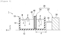
- a processing apparatus 1 according to a second embodiment and a processing method using the processing apparatus 1 will be described with reference to FIG. 3 .
- the second embodiment differs from the first embodiment in that the plasma generator 20 is positioned outside the container 10.
- the plasma generator 20 is positioned outside the container 10.
- FIG. 3 is a cross-sectional view illustrating the processing apparatus 1 according to the second embodiment. As illustrated in FIG. 3 , the electromagnetic wave transmission part 22 and the electromagnetic wave emission part 32 are positioned outside the container 10. The electromagnetic waves emitted from the electromagnetic wave transmission part 22 pass through the sidewall 14 of the container 10 and reach the electromagnetic wave receiving part 24 in the container 10.
- the sidewall 14 of the container 10 needs to transmit the electromagnetic wave (e.g., microwave). Therefore, unlike the first embodiment, at least the electromagnetic wave transmission part 22 in the container 10 is made of nonmetallic material. Examples of the material of the sidewall 14 may include glass, ceramics, rubber, and plastic.
- the electromagnetic wave transmission part 22 is positioned outside the container 10, such that the degradation of the electromagnetic wave transmission part 22 caused by the contact with the liquid medium M may be prevented. Meanwhile, because the processing apparatus 1 according to the first embodiment disposed in the container 10 and emits the electromagnetic waves, the processing apparatus 1 is advantageous because the electromagnetic waves are not attenuated by the container 10.
- the shape or size of the electromagnetic wave receiving part 24 is not limited to the above-mentioned example.
- the electromagnetic wave receiving part 24 may have any shape such as a chamber shape, a film shape, a plate shape, a stand shape, a column shape, a net shape, a fiber shape, and a spherical shape.
- the electromagnetic wave receiving part 24 may be in contact with the bottom wall 12 or the sidewall 14 of the container 10, supported at a position spaced apart from the container 10, or floated in the liquid medium M.
- the electromagnetic wave receiving part 24 may have a film or plate shape having a large area.
- the electromagnetic wave receiving part 24 may have a shape such as a stand on the bottom wall 12 and thus serve as a table for mounting the polymer compound P that is a processing object.
- the electromagnetic wave receiving part 24 may have a small spherical shape having a core-shell structure including the core 40 and the dielectric sheath 42.
- the shape of the electromagnetic wave receiving part 24 may have a plurality of concave-convex portions. This shape having the concave-convex portions is advantageous because the discharge is easily generated from the electromagnetic wave receiving part 24.
- the processing apparatus 1 illustrated in FIG. 1 was prepared.
- a microwave output device (model name: GMP30K) manufactured by Sairem was used as the electromagnetic wave transmission part 22.
- a copper wire coated with SiO 2 glass was used as the electromagnetic wave receiving part 24.
- PET polyethylene terephthalate
- the amount of inputted PET and ET was set so that a mass ratio between PET and ET was 3:97.
- the electromagnetic wave output part 30 was operated, and the electromagnetic wave emission part 32 emitted microwaves to the electromagnetic wave receiving part 24 in the atmosphere.
- the output of the microwave was set to 300 W, and the emission of the microwaves was continuously performed for 10 minutes.
- the ethylene glycol was heated by the microwaves, such that the temperature of the ethylene glycol was maintained to be about 100°C while the emission was performed continuously. As a result, a spark was generated at the periphery of the electromagnetic wave receiving part 24, and then plasma light-emitting was continuously observed on the electromagnetic wave receiving part 24.
- the decomposition product dissolved in ethylene glycol in the container 10 was detected by using an ultra-performance liquid chromatography device (model name: ACQUITY UPLC system D) manufactured by Water.
- the analysis conditions were set as follows.
- the amount of detected decomposition product was converted into the number of moles of PET, which was a raw material, and a value made by dividing the converted number of moles of PET by the overall number of moles of PET inputted as a raw material was calculated as a "decomposition ratio". That is, the "decomposition ratio" refers to a ratio of a value, which is made by converting the amount of monomer, dimer, and trimer of the detected BHET into the amount of substance of PET, to the amount of substance of inputted PET.
- the decomposition ratio was 37%. That is, it was ascertained that 37 mol% of inputted PET were decomposed into the monomer, dimer, or trimer of the BHET by the processing apparatus 1.
- PET was processed in the same way as Example 1, except that the microwave emission time was increased from 10 minutes to 25 minutes.
- the decomposition ratio of PET was 87%.
- PET was processed in the same way as Example 1, except that an oil bath was used to maintain a temperature of the container 10 at 100°C without emitting microwaves and installing the electromagnetic wave receiving part 24 in the container 10. The decomposition of PET was not observed, and the decomposition ratio was 0%.
- PET was processed in the same way as Example 1, except that a microwave output was adjusted while microwaves were emitted to maintain a temperature of ethylene glycol, which was a liquid medium, at about 100°C without installing the electromagnetic wave receiving part 24 in the container 10.
- the decomposition of PET was not observed, and the decomposition ratio was 0%.
Landscapes
- Chemical & Material Sciences (AREA)
- Organic Chemistry (AREA)
- Health & Medical Sciences (AREA)
- Chemical Kinetics & Catalysis (AREA)
- Sustainable Development (AREA)
- Polymers & Plastics (AREA)
- Medicinal Chemistry (AREA)
- Life Sciences & Earth Sciences (AREA)
- Physics & Mathematics (AREA)
- Toxicology (AREA)
- General Health & Medical Sciences (AREA)
- Engineering & Computer Science (AREA)
- Plasma & Fusion (AREA)
- Spectroscopy & Molecular Physics (AREA)
- Electromagnetism (AREA)
- Physical Or Chemical Processes And Apparatus (AREA)
- Separation, Recovery Or Treatment Of Waste Materials Containing Plastics (AREA)
Abstract
Description
- This application claims priority to and the benefit of
Japanese Patent Application No. 2022-62848 filed with the Japanese Patent Office on April 5, 2022 - Embodiments of the present invention relate to a processing apparatus, a method of manufacturing a decomposition product, and a processing method.
- A chemical recycling technology, which performs a depolymerization reaction to decompose a polymer compound into monomers and use the monomers that are raw materials, has attracted attention and has been developed.
Patent Document 1 discloses a technology that decomposes a polymer compound by using a catalyst. Patent Document 2 discloses a technology that performs a depolymerization reaction under a high temperature and a high pressure by irradiating polyester with microwaves in the presence of water. -
- Patent Document 1:
Japanese Patent Laid-Open No. 2008-88096 - Patent Document 2:
Japanese Patent Laid-Open No. 2015-168741 - However, in the case of the technology of
Patent Document 1, it is necessary to eliminate the catalyst during a post-process. The technology of Patent Document 2 requires a special reaction condition such as a high temperature and a high pressure. Therefore, there is a need to more efficiently perform the decomposition of the polymer compound. - The present invention has been made in an effort to provide a processing apparatus, a method of manufacturing a decomposition product, and a processing method, which are capable of improving efficiency in decomposing and processing a polymer compound.
- The present invention may include the following aspects.
- [1] A processing apparatus for a polymer compound, the processing apparatus including: a container configured to accommodate a polymer compound and a liquid medium; and a plasma generator disposed in the container and configured to perform plasma processing on the liquid medium.
- [2] In [1], the plasma generator includes: an electromagnetic wave transmission part configured to transmit electromagnetic waves; and an electromagnetic wave receiving part configured to receive the electromagnetic waves from the electromagnetic wave transmission part.
- [3] In [2], the electromagnetic wave receiving part performs the plasma processing on the liquid medium in response to the reception of the electromagnetic waves.
- [4] In [2], the electromagnetic wave is a microwave with a frequency of 100 MHz or more and 300 GHz or less.
- [5] In [2], the electromagnetic wave receiving part includes a metallic material.
- [6] In [2], the electromagnetic wave receiving part includes: a core having conductivity; and a dielectric material sheath configured to at least partially cover the core.
- [7] In [2], the electromagnetic wave receiving part is disposed inside the container and comes into contact with the liquid medium.
- [8] In [2], at least a part of the electromagnetic wave transmission part is disposed inside the container.
- [9] In [2], the electromagnetic wave transmission part is disposed outside the container, and a portion of the container, through which the electromagnetic waves from the electromagnetic wave transmission part at least pass, is made of a nonmetallic material.
- [10] A method, which manufactures a decomposition product by processing a polymer compound, the method including: bringing the polymer compound into contact with plasma generated from a liquid medium.
- [11] In [10], the method further includes: emitting electromagnetic waves to the electromagnetic wave receiving part in a state in which the liquid medium is in contact with the electromagnetic wave receiving part.
- [12] In [11], the electromagnetic wave receiving part performs the plasma processing on the liquid medium in response to the reception of the electromagnetic waves.
- [13] In any one of [10], [11], and [12], the method further includes: generating a radical of the liquid medium by performing plasma processing on the liquid medium.
- [14] In [10], the method further includes: performing plasma processing on the liquid medium in a state in which the polymer compound is dissolved or dispersed in the liquid medium that is not converted into plasma.
- [15] In [10], the polymer compound comes into contact with the plasma generated from the liquid medium under a condition of a temperature of 10°C or more and 150°C or less.
- [16] In [10], the polymer compound configured to come into contact with the plasma generated from the liquid medium under a condition of a pressure of 0.05 MPa or more and less than 1.5 MPa.
- [17] In [10], the liquid medium includes polar molecules.
- [18] In [10], the polymer compound comes into contact with the plasma generated from the liquid medium in a state in which no catalyst for a decomposition reaction for a polymer compound is present.
- [19] In [10], a decomposition product decomposed from the polymer compound is produced as the polymer compound comes into contact with the plasma generated from the liquid medium.
- [20] A method, which processes a polymer compound, the method including: bringing the polymer compound into contact with plasma generated from a liquid medium.
- According to the present invention, it is possible to provide a processing apparatus, a method of manufacturing a decomposition product, and a processing method, which are capable of improving efficiency in decomposing and processing a polymer compound.
-
-
FIG. 1 is a perspective view illustrating a processing apparatus according to a first embodiment. -
FIG. 2 is a cross-sectional view taken along line II-II inFIG. 1 and illustrating the processing apparatus according to the first embodiment. -
FIG. 3 is a cross-sectional view illustrating a processing apparatus according to a second embodiment. - 1...Processing apparatus, 10...Container, 12...Bottom wall, 14...Sidewall, 16...Mounting part, 20...Plasma generator, 22...Electromagnetic wave transmission part, 30...Electromagnetic wave output part, 32...Electromagnetic wave emission part, 24...Electromagnetic wave receiving part, 40...Core, 42...Dielectric sheath, P...Polymer compound, M...Liquid medium
- Hereinafter, a processing apparatus, a method of manufacturing a decomposition product, and a processing method according to embodiments will be described with reference to the drawings. In addition, the drawings are schematic or conceptual. A relationship between a thickness and a width of each part, a ratio between sizes of parts, and the like are not necessarily the same as those of actual parts. In addition, even though the identical parts are indicated, dimensions or ratios of the identical parts are sometimes differently illustrated in accordance with the drawings. In addition, an XYZ coordinate illustrated in the drawings is defined for the convenience of description but does not limit the invention.
- A
processing apparatus 1 according to a first embodiment and a processing method using theprocessing apparatus 1 will be described with reference toFIGS. 1 and2 . -
FIG. 1 is a perspective view illustrating theprocessing apparatus 1 according to the first embodiment. -
FIG. 2 is a cross-sectional view taken along line II-II inFIG. 1 and illustrating theprocessing apparatus 1 according to the first embodiment. - According to the present embodiment, the
processing apparatus 1 is provided as aprocessing apparatus 1 for a polymer compound P and includes acontainer 10 configured to accommodate the polymer compound P and a liquid medium M, and aplasma generator 20 disposed in thecontainer 10 and configured to perform plasma processing on the liquid medium M. - The
processing apparatus 1 refers to an apparatus for processing the polymer compound P. Specifically, theprocessing apparatus 1 may decompose or depolymerize the polymer compound P. - The
container 10 provides a reaction field for a processing reaction of the polymer compound P. As illustrated inFIGS. 1 and2 , thecontainer 10 has abottom wall 12, and asidewall 14 protruding upward from thebottom wall 12. Thecontainer 10 may further include a top wall installed at an upper side of thesidewall 14. Thecontainer 10 has an internal space defined by thebottom wall 12 and thesidewall 14, and optionally, by the top wall. The internal space of thecontainer 10 may be opened to the outside or closed. - A shape of the
container 10 may be a cylindrical shape having an internal space, a polyprismatic shape, or a container shape having a bottom. However, the shape of thecontainer 10 is not limited to the above-mentioned example, and thecontainer 10 may have any shape as long as thecontainer 10 may accommodate the polymer compound P and the liquid medium M. - A material of the
container 10 may be a conductor, a semiconductor, or an insulator without being particularly limited. Examples of the material of thecontainer 10 may include metal, glass, ceramics, enamel, rubber, and plastic. Thecontainer 10 made of an inorganic material is advantageous in sufficiently preventing an influence of a decomposition reaction. - A mounting
part 16 on which an electromagneticwave transmission part 22 to be described below is mounted is installed on thesidewall 14. For example, as illustrated inFIGS. 1 and2 , the mountingpart 16 is formed as a hole into which the electromagneticwave transmission part 22 is inserted. - The liquid medium M mediates the processing on the polymer compound P by the
processing apparatus 1. The liquid medium M may serve as a dispersion medium or solvent for the polymer compound P. In the present specification, the "liquid medium" means a medium that is a liquid under atmospheric pressure. For example, the liquid medium M is a liquid at a temperature of 20°C and under atmospheric pressure. For example, a boiling point of the liquid medium M may be, but not particularly limited to, 20°C or less, 10°C or less, or 0°C or less. For example, the boiling point of the liquid medium M may be, but not particularly limited to, 20°C or more, 30°C or more, 40°C or more, 50°C or more, 60°C or more, 70°C or more, 80°C or more, 90°C or more, 100°C or more, 150°C or more, or 200°C or more. Properties, such as a viscosity, of the liquid medium M are not particularly limited. Any additive such as a dispersant or a viscosity controlling agent may added to the liquid medium M. - The type of liquid medium M is not particularly limited, and one or more types of liquid material may be used. Examples of the liquid medium M may include water, alcohol, ketone, ether, ester, carboxylic acid, amine, aromatic compound, nitrile, and alkyl halide. Examples of alcohol may include methanol, ethanol, propanol, butanol, ethylene glycol, diethylene glycol, glycerol, and allyl alcohol. Examples of ketone may include acetone, acetyl acetone, and ethyl methyl ketone. Examples of ether may include dimethyl ether, ethyl methyl ether, diethyl ether, and dibutyl ether. Examples of ester may include ethyl acetate and butyl acetate. Examples of carboxylic acid may include formic acid, acetic acid, propionic acid, and benzoic acid. Examples of amine may include aniline, ethanol amine, and diethanol amine. Examples of aromatic compound may include benzene. Examples of nitrile may include acetonitrile. Examples of alkyl halide may include chloroform and dichloro methane. The liquid medium M may be a solution in which any material is dissolved or a dispersion liquid in which any material is dispersed.
- For example, the liquid medium M contains polar molecules. This is advantageous because the liquid medium M has the polarity, and thus an interaction with electromagnetic waves, particularly, microwaves increases, such that plasma is easily produced. Particularly, the liquid medium M contains one or more materials selected from a group consisting of water, alcohol, ketone, ether, and ester.
- The polymer compound P is an object to be processed by the
processing apparatus 1. The polymer compound P may be a polymer or oligomer made by polymerizing one or two or more types of monomers. For example, the polymer compound P may be, but not particularly limited to, polyolefin (polyethylene, polypropylene, etc.), polyester (polyethylene terephthalate, etc.), polyether, polyurethane, polyamide (polyacrylic amide etc.), polyimide, polycarbonate, polyacetal, epoxy resin, polystyrene, polyvinyl halide (polyvinyl chloride etc.), fluorine resin, polyvinyl alcohol, acrylonitrile·butadiene·styrene copolymer synthetic resin (ABS resin), synthetic rubber, and fiber reinforced plastic. - The polymer compound P is in contact with the liquid medium M in the
container 10. Specifically, as illustrated inFIGS. 1 and2 , the polymer compound P is a particulate and may be dispersed in the liquid medium M or dissolved in the liquid medium M. However, the presence form of the polymer compound P is not limited to the above-mentioned example. For example, the polymer compound P is a lump sized to be visible and may be present in the liquid medium M. For example, the polymer compound P may be mounted on abottom wall 12 or a mounting table installed in thecontainer 10. - For example, a mass ratio between the polymer compound P and the liquid medium M is 0.001:99.999 to 50:50, 0.01:99.99 to 30:70, 0.1:99.9 to 20:80, 1:99 to 10:90, or 2:98 to 5:95.
- The
plasma generator 20 performs the plasma processing on the liquid medium M. Specifically, theplasma generator 20 may generate plasma from the liquid medium M by performing the plasma processing on the liquid medium M in thecontainer 10. Specifically, as illustrated inFIGS. 1 and2 , theplasma generator 20 includes the electromagneticwave transmission part 22 configured to transmit electromagnetic waves, and an electromagneticwave receiving part 24 configured to receive electromagnetic waves from the electromagneticwave transmission part 22. - The electromagnetic
wave transmission part 22 transmits the electromagnetic waves to the electromagneticwave receiving part 24. The electromagneticwave transmission part 22 outputs the electromagnetic waves to generate plasma from the liquid medium M in cooperation with the electromagneticwave receiving part 24. The configuration of the electromagneticwave transmission part 22 is not particularly limited, and the electromagneticwave transmission part 22 may have any configuration capable of transmitting electromagnetic waves. For example, as illustrated inFIGS. 1 and2 , the electromagneticwave transmission part 22 includes an electromagneticwave output part 30 configured to output electromagnetic waves, and an electromagneticwave emission part 32 configured to emit the electromagnetic waves, which are outputted from the electromagneticwave output part 30, to the electromagneticwave receiving part 24. The electromagneticwave output part 30 includes a power source, an oscillator configured to emit electromagnetic waves, and an amplifier configured to amplify the emitted electromagnetic waves. The electromagneticwave emission part 32 serves as a transmission antenna for emitting electromagnetic waves into thecontainer 10. The electromagneticwave emission part 32 is mounted on the mountingpart 16. Therefore, the electromagneticwave emission part 32 is partially positioned inside thecontainer 10 and partially positioned outside thecontainer 10. Therefore, a part of the electromagneticwave transmission part 22 is positioned inside thecontainer 10, and the other part of the electromagneticwave transmission part 22 is positioned outside thecontainer 10. In addition, the entire electromagneticwave transmission part 22 may be disposed in thecontainer 10. That is, at least a part of the electromagneticwave transmission part 22 may be disposed in thecontainer 10. The electromagneticwave emission part 32 may be integrated with thecontainer 10, or the entire electromagneticwave transmission part 22 may be integrated with thecontainer 10. - The electromagnetic
wave receiving part 24 is irradiated with the electromagnetic waves emitted from the electromagneticwave transmission part 22, thereby allowing the electromagneticwave receiving part 24 to emit electrons. For example, the electromagnetic wave is the microwave with a frequency of 100 MHz or more and 300 GHz or less. More specifically, the frequency of the electromagnetic wave may be 2.45 GHz, which is recognized for domestic use in Japan, or 915 MHz used for food thawing. - The electromagnetic
wave receiving part 24 serves as a receiving antenna configured to receive the electromagnetic waves transmitted from the electromagneticwave transmission part 22. The electromagneticwave receiving part 24 emits electrons from a surface thereof in response to the reception of the electromagnetic waves from the electromagneticwave transmission part 22. The emitted electrons attack and activate the liquid medium M in thecontainer 10, thereby generate plasma from the liquid medium M. For example, the electromagneticwave receiving part 24 includes a metallic material. - The electromagnetic
wave receiving part 24 is disposed in thecontainer 10. The electromagneticwave receiving part 24 is in contact with the liquid medium M. Specifically, as illustrated inFIGS. 1 and2 , the electromagneticwave receiving part 24 extends upward (in a Z direction) from thebottom wall 12 of thecontainer 10 and has a long, thin shape. In addition, the electromagneticwave receiving part 24 may be integrated with thecontainer 10. The number of electromagneticwave receiving parts 24 is not particularly limited. - The electromagnetic
wave receiving part 24 includes a core 40 having conductivity, and adielectric sheath 42 configured to at least partially cover thecore 40. As illustrated inFIGS. 1 and2 , an outer surface of thecore 40 is covered by thedielectric sheath 42. - The
core 40 is a conductive member including a metallic material. When the electromagnetic waves (e.g., microwaves) are emitted, thecore 40 emits free electrons from a surface thereof. The emitted electrons pass through thedielectric sheath 42 that covers thecore 40, and the electrons are emitted from the electromagneticwave receiving part 24 and generate plasma from the liquid medium M. - For example, a material of the
core 40 is metal. Examples of the metallic material may include single metal such as copper, iron, aluminum, magnesium, titanium, vanadium, chromium, manganese, cobalt, nickel, zinc, germanium, palladium, indium, tin, silver, molybdenum, tantalum, tungsten, gold, and platinum, an alloy containing one or more of the above-mentioned elements as a main component, metal oxide having physical properties of metal, metal carbide, metal silicide, metal nitride, and a composite material containing the above-mentioned elements as a base. - The
dielectric sheath 42 covers a part or the entirety of a periphery of thecore 40. Thedielectric sheath 42 inhibits elution of the core 40 to the liquid medium M. Thedielectric sheath 42 inhibits a reaction between the metal element, which constitutes the core 40, and the liquid medium M or oxygen in air. Therefore, thedielectric sheath 42 may serve as a protective layer that prevents corrosion of thecore 40. Meanwhile, thedielectric sheath 42 may at least partially transmit the electromagnetic waves emitted from the electromagneticwave transmission part 22 and the electrons emitted from thecore 40. In addition, when the electrons, which do not pass through thedielectric sheath 42 among the electrons emitted from thecore 40, are accumulated inside thedielectric sheath 42, a potential difference may occur at two opposite sides of thedielectric sheath 42. Therefore, thedielectric sheath 42 generates dielectric polarization and generates charges on the surface of thedielectric sheath 42. All the electrons passing through thedielectric sheath 42 and the charges generated on the surface of thedielectric sheath 42 by the dielectric polarization may contribute to the generation of plasma from the liquid medium M. - A material of the
dielectric sheath 42 is a dielectric material. Examples of the material of thedielectric sheath 42 may include glass and ceramics. Examples of glass may include amorphous silicon oxide (e.g., silicon dioxide SiO2), soda lime glass, quartz glass, silicate glass, and borosilicate glass. Examples of ceramics may include an inorganic material (e.g., diamond, silicon, carbon fiber, silicon carbide, fullerene, or boron carbide) that does not include metal oxide, metal carbide, metal silicide, metal nitride, or metal element. - For example, a thickness of the
dielectric sheath 42 is 1 um to 500 um, 10 um to 300 µm, or 50 um to 200 um. When the thickness is 1 µm or more, it is possible to ensure predetermined insulation and reduce a likelihood of an insulation breakdown. When the thickness is 500 µm or less, it is possible to reduce a likelihood that the electrons cannot pass through thedielectric sheath 42. - The
dielectric sheath 42 is interposed between the core 40 and the external structure (e.g., the container 10) and serves to prevent the core 40 from being grounded. For example, when thecore 40 is grounded by being in direct contact with thecontainer 10 made of metal, the electrons of the core 40 excited by the electromagnetic waves come out to thecontainer 10, and for this reason, there is a likelihood that the generation of plasma from the liquid medium M cannot be efficiently performed. That is, thedielectric sheath 42 electrically insulates thecore 40 and the external structure. A portion of thedielectric sheath 42, which is positioned between the core 40 and the external structure, may have a thickness that does not substantially transmit the electrons. For example, as illustrated inFIG. 2 , a bottom portion of thedielectric sheath 42, which is positioned between the core 40 and thebottom wall 12 may have a larger thickness than the other portions. - For example, a distance d between the core 40 and a tip of the electromagnetic
wave emission part 32 illustrated inFIG. 2 satisfiesRelationship Formula 1 below. For example, d=λ/4. For example, in case that the electromagneticwave emission part 32 emits microwaves with a frequency of 2.45 GHz, d may be 27 mm or more and 34 mm or less. The configuration in which d satisfiesRelationship Formula 1 is advantageous because the electromagneticwave receiving part 24 stably generates plasma.
- Next, a method of using the
processing apparatus 1 will be described. - According to the present embodiment, a method of processing the polymer compound P includes bringing the polymer compound P into contact with the plasma generated from the liquid medium M.
- As another embodiment, a method of manufacturing a decomposition product according to the present embodiment is a method of manufacturing a decomposition product by processing the polymer compound P, the method including bringing the polymer compound P into contact with the plasma generated from the liquid medium M.
- Specifically, the method of processing the polymer compound P or the method of manufacturing a decomposition product may include the following steps. Hereinafter, the processing of the polymer compound P will be described sequentially for respective steps.
- First, before the plasma processing is performed on the liquid medium M, the liquid medium M and the polymer compound P may be mixed in the
container 10. Prior to this step, the polymer compound P may be ground. For example, the polymer compound P in a particulate state may be dispersed in the liquid medium M or dissolved in the liquid medium M. In addition, the timing of inputting the polymer compound P into the liquid medium M is not limited to the above-mentioned example. For example, the polymer compound P may be inputted into the liquid medium M at the same time as the plasma processing of the liquid medium M. In addition, after the plasma processing is performed on the liquid medium M, the polymer compound P may be inputted into the liquid medium M on which the plasma processing has been performed. - Next, the plasma processing is performed on the liquid medium M in the
container 10. Specifically, as illustrated inFIGS. 1 and2 , in the state in which the liquid medium M and the polymer compound P are accommodated in thecontainer 10, the electromagneticwave transmission part 22 operates and emits electromagnetic waves to the electromagneticwave receiving part 24 in thecontainer 10. Thecore 40 of the electromagneticwave receiving part 24 receives energy of the electromagnetic waves and emits free electrons from the surface thereof. At least some of the free electrons emitted from the core 40 pass through thedielectric sheath 42 and collide with molecules of the liquid medium M at the periphery of the electromagneticwave receiving part 24. The collision of the electrons generates plasma from a part of the liquid medium M, thereby emitting light. The excited electrons are caught between the molecules of the liquid medium M. The molecules of the liquid medium M are radicalized and/or ionized. For example, it is estimated that in case that the liquid medium M is ethylene glycol, the attack from the electrons generates charges on carbon atoms, oxygen atoms, and hydrogen atoms in the structure of ethylene glycol. However, the structure of the plasma generated from the liquid medium M is not limited to the flowing description, and various variations, such as a structure having a plurality of charges, may be considered.

- In addition, when the electrons, which do not pass through the
dielectric sheath 42 among the electrons emitted from thecore 40, are accumulated inside thedielectric sheath 42, dielectric polarization may occur at two opposite sides of thedielectric sheath 42. Therefore, the charges occurring on the outer surface of thedielectric sheath 42 may also excite the liquid medium M. - When the electromagnetic
wave transmission part 22 emits electromagnetic waves to the electromagneticwave receiving part 24 in the state in which the liquid medium M is in contact with the electromagneticwave receiving part 24 as described above, thecore 40 of the electromagneticwave receiving part 24 may emit free electrons. The emitted electrons pass through thedielectric sheath 42 and/or induce the dielectric polarization of thedielectric sheath 42 and excite the liquid medium M into a plasma state. It is possible to generate radicals of the liquid medium M by performing the plasma processing on the liquid medium M as described above. - For example, a temperature at which the plasma processing is performed on the liquid medium M (e.g., a temperature of the liquid medium M at which the electromagnetic
wave transmission part 22 generates electromagnetic waves) may be, but not particularly limited to, 10°C or more and 150°C or less. For example, a temperature at which the polymer compound P comes into contact with the plasma generated from the liquid medium M may be, but not particularly limited to, 10°C or more and 150°C or less. These temperatures are substantially equal to each other when the plasma processing is performed in the state in which the polymer compound P and the liquid medium M are in contact with each other. In addition, the "temperature" in this case means an average temperature of the entire liquid medium M in thecontainer 10. - For example, the temperature at which the plasma processing is performed may be 15°C or more, 20°C or more, 25°C or more, 30°C or more, 40°C or more, 50°C or more, 60°C or more, 70°C or more, 80°C or more, 90°C or more, or 100°C or more. For example, the temperature at which the plasma processing is performed may be 140°C or less, 120°C or less, 100°C or less, 80°C or less, 60°C or less, 50°C or less, 40°C or less, or 30°C or less.
- For example, the temperature at which the polymer compound P comes into contact with the plasma generated from the liquid medium M may be 15°C or more, 20°C or more, 25°C or more, 30°C or more, 40°C or more, 50°C or more, 60°C or more, 70°C or more, 80°C or more, 90°C or more, or 100°C or more. For example, the temperature at which the polymer compound P comes into contact with the plasma generated from the liquid medium M may be 140°C or less, 120°C or less, 100°C or less, 80°C or less, 60°C or less, 50°C or less, 40°C or less, or 30°C or less.
- In principle, because an active heating operation need not be performed to perform the plasma processing on the liquid medium M, it is advantageous, in terms of costs and efficiency, to perform the plasma processing on the liquid medium M without heating the
container 10 or the liquid medium M. The temperature at which the plasma processing is performed on the liquid medium M and/or the temperature at which the polymer compound P comes into contact with the plasma generated from the liquid medium M may be a room temperature. However, there is a likelihood that the liquid medium M may be heated by molecules of plasma generated from another liquid medium M or the electromagnetic waves (e.g., microwaves). In this case, the temperature of the liquid medium M may increase while the electromagnetic waves are emitted during the plasma processing on the liquid medium M. To prevent evaporation of the liquid medium M, the output of the electromagnetic waves may be adjusted to prevent the temperature from exceeding the boiling point of the liquid medium M. - A pressure at which the plasma processing is performed on the liquid medium M and/or a pressure at which the polymer compound P comes into contact with the plasma generated from the liquid medium M may be, but not particularly limited to, 0.05 MPa or more and less than 1.5 MPa. For example, a pressure at which the plasma processing is performed may be 0.06 MPa or more, 0.07 MPa or more, 0.08 MPa or more, 0.09 MPa or more, 0.1 MPa or more, or atmospheric pressure or higher. For example, the pressure at which the plasma processing is performed may be 1.4 MPa or less, 1.3 MPa or less, 1.2 MPa or less, 1.1 MPa or less, or atmospheric pressure or lower.
- In principle, because an active pressurization operation need not be performed to perform the plasma processing on the liquid medium M, it is advantageous, in terms of costs and efficiency, to perform the plasma processing on the liquid medium M without pressurizing the internal space of the
container 10 or the liquid medium M. Particularly, the plasma processing on the liquid medium M and/or the contact between the polymer compound P and the plasma generated from the liquid medium M may be performed under atmospheric pressure. For example, in case that thecontainer 10 is opened to the outside, the method may be performed under atmospheric pressure. - The plasma generated from the liquid medium M is in a chemically unstable state and thus has very high reactivity. Therefore, the plasma generated from the liquid medium M reacts with the polymer compound P and decomposes the polymer compound P. For example, unpaired electrons of the radical generated from the liquid medium M attack the polymer compound P. Therefore, one or more bonded structures, among the structures of the polymer compound P, are cut, such that the polymer compound P is decomposed into polymers or oligomers having smaller molecular weights and/or monomers that are minimum constituent units of the polymer compound P. As described above, in a state in which the liquid medium M, which is not converted into plasma, is in contact with the polymer compound P, the plasma processing is performed on the liquid medium M, such that the plasma generated from the liquid medium M may decompose the polymer compound P. More specifically, in a state in which the polymer compound P is dissolved or dispersed in the liquid medium M that is not converted into plasma, the plasma processing is performed on the liquid medium M, such that the plasma generated from the liquid medium M may decompose the polymer compound P. As the polymer compound P comes into contact with the plasma generated from the liquid medium M as described above, the decomposition product decomposed from the polymer compound P is produced.
- The decomposition of the polymer compound P does not require a catalyst. That is, the polymer compound P comes into contact with the plasma generated from the liquid medium M in a state in which no catalyst for decomposition reaction for the polymer compound is present. Therefore, this process is efficient because costs may be reduced in comparison with the decomposition processing using a catalyst.
- The generated decomposition product is separated and recovered from the liquid medium M and the remaining polymer compound P. The method of recovering the generated decomposition product is not particularly limited and may be performed by using one or more existing techniques. Examples of the recovery method may include drying, filtration, extraction, distillation, purification, and chromatography. Examples of chromatography may include high-performance liquid chromatography (HPLC) and ultra-performance liquid chromatography (UPLC). For example, in case that the decomposition product is dissolved in the liquid medium M and the polymer compound P is not dissolved in the liquid medium M, the polymer compound P and the liquid medium M in which the decomposition product is dissolved are separated first. Thereafter, the decomposition product may be recovered by separating the decomposition product from the liquid medium M. In this way, with the processing of the polymer compound P, the decomposition product may be manufactured from the polymer compound P.
- According to the
processing apparatus 1 and the method described above, the decomposition of the polymer compound P may be efficiently performed without requiring a catalyst and performing an active heating or pressurization operation. Therefore, it is possible to efficiently reuse the polymer compound P. Therefore, it is possible to contribute to a reduction in environment load or an implementation of circular economy. - A
processing apparatus 1 according to a second embodiment and a processing method using theprocessing apparatus 1 will be described with reference toFIG. 3 . - The second embodiment differs from the first embodiment in that the
plasma generator 20 is positioned outside thecontainer 10. Hereinafter, a difference between the embodiments will be mainly described, and a repeated description of the common parts of the embodiments will not be described. -
FIG. 3 is a cross-sectional view illustrating theprocessing apparatus 1 according to the second embodiment. As illustrated inFIG. 3 , the electromagneticwave transmission part 22 and the electromagneticwave emission part 32 are positioned outside thecontainer 10. The electromagnetic waves emitted from the electromagneticwave transmission part 22 pass through thesidewall 14 of thecontainer 10 and reach the electromagneticwave receiving part 24 in thecontainer 10. - As described above, the
sidewall 14 of thecontainer 10 needs to transmit the electromagnetic wave (e.g., microwave). Therefore, unlike the first embodiment, at least the electromagneticwave transmission part 22 in thecontainer 10 is made of nonmetallic material. Examples of the material of thesidewall 14 may include glass, ceramics, rubber, and plastic. - In the
processing apparatus 1 according to the second embodiment, the electromagneticwave transmission part 22 is positioned outside thecontainer 10, such that the degradation of the electromagneticwave transmission part 22 caused by the contact with the liquid medium M may be prevented. Meanwhile, because theprocessing apparatus 1 according to the first embodiment disposed in thecontainer 10 and emits the electromagnetic waves, theprocessing apparatus 1 is advantageous because the electromagnetic waves are not attenuated by thecontainer 10. - The shape or size of the electromagnetic
wave receiving part 24 is not limited to the above-mentioned example. For example, the electromagneticwave receiving part 24 may have any shape such as a chamber shape, a film shape, a plate shape, a stand shape, a column shape, a net shape, a fiber shape, and a spherical shape. The electromagneticwave receiving part 24 may be in contact with thebottom wall 12 or thesidewall 14 of thecontainer 10, supported at a position spaced apart from thecontainer 10, or floated in the liquid medium M. - For example, the electromagnetic
wave receiving part 24 may have a film or plate shape having a large area. The electromagneticwave receiving part 24 may have a shape such as a stand on thebottom wall 12 and thus serve as a table for mounting the polymer compound P that is a processing object. The electromagneticwave receiving part 24 may have a small spherical shape having a core-shell structure including thecore 40 and thedielectric sheath 42. The shape of the electromagneticwave receiving part 24 may have a plurality of concave-convex portions. This shape having the concave-convex portions is advantageous because the discharge is easily generated from the electromagneticwave receiving part 24. - First, the
processing apparatus 1 illustrated inFIG. 1 was prepared. A microwave output device (model name: GMP30K) manufactured by Sairem was used as the electromagneticwave transmission part 22. A copper wire coated with SiO2 glass was used as the electromagneticwave receiving part 24. Ethylene glycol (EG), as the liquid medium M, was inputted into thecontainer 10 made of SiO2 glass. Next, powder made by grinding polyethylene terephthalate (PET) into small pieces was prepared as the polymer compound P of the processing object, and the powder was inputted into thecontainer 10 and dispersed in ethylene glycol. The amount of inputted PET and ET was set so that a mass ratio between PET and ET was 3:97. - Next, the electromagnetic
wave output part 30 was operated, and the electromagneticwave emission part 32 emitted microwaves to the electromagneticwave receiving part 24 in the atmosphere. The output of the microwave was set to 300 W, and the emission of the microwaves was continuously performed for 10 minutes. The ethylene glycol was heated by the microwaves, such that the temperature of the ethylene glycol was maintained to be about 100°C while the emission was performed continuously. As a result, a spark was generated at the periphery of the electromagneticwave receiving part 24, and then plasma light-emitting was continuously observed on the electromagneticwave receiving part 24. - After the microwaves was emitted for 10 minutes, the decomposition product dissolved in ethylene glycol in the
container 10 was detected by using an ultra-performance liquid chromatography device (model name: ACQUITY UPLC system D) manufactured by Water. The analysis conditions were set as follows. - · Stationary phase: ACQUITY UPLC BEH C8 1.7 um 100 mm
- · Mobile phase: methanol/water=7/3 (v/v)
- · Method of preparing measuring solution: the measuring solution was manufactured by diluting the decomposition product with methanol/water=7/3(v/v) and then filtering the decomposition product with a syringe filter.
- · Flow velocity: 0.4 mL/min
- · Detection wavelength: 254 nm
- As a result, it was detected that the monomer, dimer, and trimer of the bis-2-hydroxyethyl terephthalate (BHET) were dissolved in ethylene glycol. The monomer, dimer, and trimer of the detected BHET were considered as the decomposition products, and the undetected components were considered as non-decomposition products.
- The amount of detected decomposition product was converted into the number of moles of PET, which was a raw material, and a value made by dividing the converted number of moles of PET by the overall number of moles of PET inputted as a raw material was calculated as a "decomposition ratio". That is, the "decomposition ratio" refers to a ratio of a value, which is made by converting the amount of monomer, dimer, and trimer of the detected BHET into the amount of substance of PET, to the amount of substance of inputted PET. The decomposition ratio was 37%. That is, it was ascertained that 37 mol% of inputted PET were decomposed into the monomer, dimer, or trimer of the BHET by the
processing apparatus 1. - PET was processed in the same way as Example 1, except that the microwave emission time was increased from 10 minutes to 25 minutes. The decomposition ratio of PET was 87%.
- PET was processed in the same way as Example 1, except that an oil bath was used to maintain a temperature of the
container 10 at 100°C without emitting microwaves and installing the electromagneticwave receiving part 24 in thecontainer 10. The decomposition of PET was not observed, and the decomposition ratio was 0%. - PET was processed in the same way as Example 1, except that a microwave output was adjusted while microwaves were emitted to maintain a temperature of ethylene glycol, which was a liquid medium, at about 100°C without installing the electromagnetic
wave receiving part 24 in thecontainer 10. The decomposition of PET was not observed, and the decomposition ratio was 0%. - The experimental conditions of Examples and Comparative Examples and the decomposition ratio of PET are summarized in Table 1 below.
[Table 1] PET EG Electroma gnetic wave Receiving part Electrom agnetic wave Output Cata lyst Temper ature Condit ion Pressure Condition Emission Time Decompo sition ratio Example 1 3 wt% 97 wt% Presence 300 W Abse nce 100° C Atmospheric pressure 10 minutes 37% Example 2 3 wt% 97 wt% Presence 300 W Abse nce 100 °C Atmospheric pressure 25 minutes 87% Comparat ive Example 1 3 wt% 97 wt% Absence - Abse nce 100 °C Atmospheric pressure - 0% Comparat ive Example 2 3 wt% 97 wt% Absence 300 W Abse nce 100 °C Atmospheric pressure - 0%
Claims (20)
- A processing apparatus for a polymer compound, the processing apparatus comprising:a container configured to accommodate a polymer compound and a liquid medium; anda plasma generator disposed in the container and configured to perform plasma processing on the liquid medium.
- The processing apparatus of claim 1, wherein the plasma generator, which performs the plasma processing on the liquid medium in the container, comprises:an electromagnetic wave transmission part configured to transmit electromagnetic waves; andan electromagnetic wave receiving part configured to receive the electromagnetic waves from the electromagnetic wave transmission part.
- The processing apparatus of claim 2, wherein the electromagnetic wave receiving part performs the plasma processing on the liquid medium in response to the reception of the electromagnetic waves.
- The processing apparatus of claim 2, wherein the electromagnetic wave is a microwave with a frequency of 100 MHz or more and 300 GHz or less.
- The processing apparatus of claim 2, wherein the electromagnetic wave receiving part includes a metallic material.
- The processing apparatus of claim 2, wherein the electromagnetic wave receiving part comprises:a core having conductivity; anda dielectric material sheath configured to at least partially cover the core.
- The processing apparatus of claim 2, wherein the electromagnetic wave receiving part is disposed inside the container and comes into contact with the liquid medium.
- The processing apparatus of claim 2, wherein at least a part of the electromagnetic wave transmission part is disposed inside the container.
- The processing apparatus of claim 2, wherein the electromagnetic wave transmission part is disposed outside the container, and a portion of the container, through which the electromagnetic waves from the electromagnetic wave transmission part at least pass, is made of a nonmetallic material.
- A method, which manufactures a decomposition product by processing a polymer compound, the method comprising:
bringing the polymer compound into contact with plasma generated from a liquid medium. - The method of claim 10, further comprising:
emitting electromagnetic waves to the electromagnetic wave receiving part in a state in which the liquid medium is in contact with the electromagnetic wave receiving part. - The method of claim 11, wherein the electromagnetic wave receiving part performs the plasma processing on the liquid medium in response to the reception of the electromagnetic waves.
- The method of claim 10, further comprising:
generating a radical of the liquid medium by performing plasma processing on the liquid medium. - The method of claim 10, further comprising:
performing plasma processing on the liquid medium in a state in which the polymer compound is dissolved or dispersed in the liquid medium that is not converted into plasma. - The method of claim 10, wherein the polymer compound comes into contact with the plasma generated from the liquid medium under a condition of a temperature of 10°C or more and 150°C or less.
- The method of claim 10, wherein the polymer compound configured to come into contact with the plasma generated from the liquid medium under a condition of a pressure of 0.05 MPa or more and less than 1.5 MPa.
- The method of claim 10, wherein the liquid medium includes polar molecules.
- The method of claim 10, wherein the polymer compound comes into contact with the plasma generated from the liquid medium in a state in which no catalyst for a decomposition reaction for a polymer compound is present.
- The method of claim 10, wherein a decomposition product decomposed from the polymer compound is produced as the polymer compound comes into contact with the plasma generated from the liquid medium.
- A method, which processes a polymer compound, the method comprising:
bringing the polymer compound into contact with plasma generated from a liquid medium.
Applications Claiming Priority (2)
| Application Number | Priority Date | Filing Date | Title |
|---|---|---|---|
| JP2022062848A JP7399209B2 (en) | 2022-04-05 | 2022-04-05 | Treatment equipment, method for producing decomposition products, and treatment method |
| PCT/KR2022/014120 WO2023195586A1 (en) | 2022-04-05 | 2022-09-21 | Treatment apparatus, method for preparing degradation product, and treatment method |
Publications (2)
| Publication Number | Publication Date |
|---|---|
| EP4332157A1 true EP4332157A1 (en) | 2024-03-06 |
| EP4332157A4 EP4332157A4 (en) | 2024-12-11 |
Family
ID=88242998
Family Applications (1)
| Application Number | Title | Priority Date | Filing Date |
|---|---|---|---|
| EP22936639.8A Pending EP4332157A4 (en) | 2022-04-05 | 2022-09-21 | TREATMENT DEVICE, METHOD FOR PRODUCING A DEGRADATION PRODUCT AND TREATMENT METHOD |
Country Status (7)
| Country | Link |
|---|---|
| US (1) | US20240279153A1 (en) |
| EP (1) | EP4332157A4 (en) |
| JP (1) | JP7399209B2 (en) |
| KR (1) | KR20240011684A (en) |
| CN (1) | CN117396547A (en) |
| TW (1) | TWI861722B (en) |
| WO (1) | WO2023195586A1 (en) |
Family Cites Families (28)
| Publication number | Priority date | Publication date | Assignee | Title |
|---|---|---|---|---|
| US5015349A (en) * | 1988-12-23 | 1991-05-14 | University Of Connecticut | Low power density microwave discharge plasma excitation energy induced chemical reactions |
| JP3065222B2 (en) * | 1994-12-05 | 2000-07-17 | 株式会社高岳製作所 | Polymer compound decomposition equipment |
| JP2003292594A (en) * | 2002-02-01 | 2003-10-15 | Kubota Corp | Method for producing polyester resin |
| JP2005277397A (en) * | 2004-02-26 | 2005-10-06 | Tokyo Electron Ltd | Plasma processing equipment |
| JP3769625B1 (en) * | 2004-12-21 | 2006-04-26 | 国立大学法人愛媛大学 | Liquid plasma generator and liquid plasma generation method |
| TWI405608B (en) * | 2005-03-25 | 2013-08-21 | 三菱麗陽股份有限公司 | Surface treatment method and surface treated article |
| DE112006000772T5 (en) * | 2005-03-30 | 2008-01-24 | Ehime University | Process for producing an amorphous carbon film |
| WO2007026167A1 (en) * | 2005-09-02 | 2007-03-08 | Haydale Limited | Processing of particulate materials, recycling methods, especially for rubber |
| US7897651B2 (en) * | 2005-12-09 | 2011-03-01 | Kazutoshi Ikenaga | Method for depolymerizing polyester and unsaturated polyester, and method for recovering polyester monomer using the depolymerization |
| TWI327154B (en) * | 2006-06-12 | 2010-07-11 | Univ Lunghwa Sci & Technology | Device and related method for decomposing polymer materials using h2o plasma |
| JP5189266B2 (en) | 2006-09-29 | 2013-04-24 | 株式会社ニスコ | Method for producing bis- (2-hydroxyethyl) terephthalate and method for producing polyethylene terephthalate |
| JP4889124B2 (en) * | 2007-11-01 | 2012-03-07 | 光弘 渡邉 | Fluid processing equipment |
| KR20090108874A (en) * | 2008-04-14 | 2009-10-19 | 한국기초과학지원연구원 | Biodegradation rate and hydrophilicity improvement method of biodegradable polymer resin by plasma surface treatment |
| FR2942149B1 (en) * | 2009-02-13 | 2012-07-06 | Camille Cie D Assistance Miniere Et Ind | METHOD AND SYSTEM FOR VALORIZING MATERIALS AND / OR PRODUCTS BY PULSE POWER |
| HUE049112T2 (en) * | 2010-12-08 | 2020-09-28 | Pravansu S Mohanty | Depolymerization process |
| JP5817960B2 (en) * | 2011-02-28 | 2015-11-18 | 国立大学法人北海道大学 | Metal recovery method and metal recovery apparatus |
| JP6145600B2 (en) * | 2011-07-16 | 2017-06-14 | イマジニアリング株式会社 | Plasma generator, internal combustion engine, and analyzer |
| US8466332B1 (en) * | 2011-12-21 | 2013-06-18 | Climax Global Energy | Method and apparatus for microwave depolymerization of hydrocarbon feedstocks |
| JP6040506B2 (en) * | 2012-08-27 | 2016-12-07 | 国立大学法人名古屋大学 | Decomposition method of alginic acid and composition comprising alginic acid and / or derivatives thereof |
| JP2015168741A (en) | 2014-03-06 | 2015-09-28 | 大和製罐株式会社 | Polyester depolymerization method and polyester raw material recovery method using the depolymerization method |
| JP2019119821A (en) * | 2018-01-10 | 2019-07-22 | 国立大学法人愛媛大学 | Method for decomposition of carbon fiber-reinforced plastic and method for producing carbon black |
| JP6799549B2 (en) * | 2018-01-16 | 2020-12-16 | 東京エレクトロン株式会社 | How to clean parts of plasma processing equipment |
| CN209508118U (en) * | 2018-12-24 | 2019-10-18 | 厦门大学 | A kind of plasma plastic degradation device |
| US20220168702A1 (en) * | 2019-04-05 | 2022-06-02 | Pyrowave Inc. | Microwave pyrolysis reactor |
| KR102266926B1 (en) * | 2019-06-19 | 2021-06-18 | 한양대학교 산학협력단 | Gasification units of polymer film and insecticide apparatus having the same |
| KR20210001000A (en) * | 2019-06-26 | 2021-01-06 | 인천대학교 산학협력단 | manufacturing method of low molecular weight chitosan using solution phase plasma |
| JP2021161338A (en) * | 2020-04-02 | 2021-10-11 | 日本プラスト株式会社 | Method for decomposing thermoplastic polyurethane |
| JP7322852B2 (en) | 2020-10-09 | 2023-08-08 | トヨタ自動車株式会社 | Misfire detection device for internal combustion engine |
-
2022
- 2022-04-05 JP JP2022062848A patent/JP7399209B2/en active Active
- 2022-09-21 CN CN202280038350.XA patent/CN117396547A/en active Pending
- 2022-09-21 EP EP22936639.8A patent/EP4332157A4/en active Pending
- 2022-09-21 WO PCT/KR2022/014120 patent/WO2023195586A1/en not_active Ceased
- 2022-09-21 KR KR1020237038407A patent/KR20240011684A/en active Pending
- 2022-09-21 US US18/562,932 patent/US20240279153A1/en active Pending
-
2023
- 2023-02-14 TW TW112105157A patent/TWI861722B/en active
Also Published As
| Publication number | Publication date |
|---|---|
| EP4332157A4 (en) | 2024-12-11 |
| JP2023153525A (en) | 2023-10-18 |
| WO2023195586A1 (en) | 2023-10-12 |
| JP7399209B2 (en) | 2023-12-15 |
| US20240279153A1 (en) | 2024-08-22 |
| TWI861722B (en) | 2024-11-11 |
| CN117396547A (en) | 2024-01-12 |
| KR20240011684A (en) | 2024-01-26 |
| TW202340351A (en) | 2023-10-16 |
Similar Documents
| Publication | Publication Date | Title |
|---|---|---|
| Fan et al. | Efficient glycolysis of PET catalyzed by a metal-free phosphazene base: the important role of EG− Electronic supplementary information (ESI) available. See | |
| AU2017200238B2 (en) | Depolymerization processes, apparatuses and catalysts for use in connection therewith | |
| US8945673B2 (en) | Nanoparticles with grafted organic molecules | |
| JP2010264439A (en) | Method and apparatus for treating process volume with multiple electromagnetic generator | |
| US8256695B2 (en) | Method for purification of semiconducting single wall nanotubes | |
| Kinzyabaeva et al. | A selective synthesis of the fullerene-fused dioxane adduct via heterogeneous reaction of C60 with α-diols and NaOH under ultrasonication | |
| US20240279153A1 (en) | Treatment Apparatus, Method for Preparing Degradation Product, and Treatment Method | |
| Kozlov et al. | Synthesis of organic compounds from mixtures of methane with carbon dioxide in dielectric-barrier discharges at atmospheric pressure | |
| Gupta et al. | General Characteristics and Applications of Microwaves in Organic Synthesis. | |
| US20150017076A1 (en) | Method and apparatus for excitation of resonances in molecules | |
| Li et al. | Co-upcycling of polyethylene terephthalate and polyoxymethylene into valuable chemicals | |
| JP5817960B2 (en) | Metal recovery method and metal recovery apparatus | |
| Lee et al. | Uncatalyzed N-Alkylation of Amines in Ionic Wind from Ambient Corona Discharge | |
| US9623397B2 (en) | System for processing hydrocarbon fuels using surfaguide | |
| KR20240173684A (en) | Polymer degradation system, polymer degradation method, and manufacturing method of degradation products | |
| Nastase et al. | Depolymerization of inulin in the highly reactive gas phase of a non thermal plasma at atmospheric pressure | |
| KR20070121692A (en) | Amorphous Carbon Film Manufacturing Method | |
| Besov et al. | Acceleration of acetone destruction process under synergistic action of photocatalytic oxidation and barrier discharge | |
| US9044730B2 (en) | System for processing hydrocarbon fuels using surfaguide | |
| Chen et al. | Grafting of N‐moieties onto octa‐methyl polyhedral oligomeric silsesquioxane microstructures by sequential continuous wave and pulsed plasma | |
| CN104787735A (en) | Method for synthesizing hydrazine | |
| Kudryashov et al. | Study of the products of benzene transformation in the presence of argon, hydrogen, and propane-butane mixture in barrier discharge | |
| WO2002090261A2 (en) | Process for obtaining alpha-campholenic aldehyde | |
| Hagiwara et al. | Sequential knoevenagel reaction/mislow-evans rearrangement catalyzed by heterogeneous amine grafted on silica in water, leading to γ-hydroxy-α, β-unsaturated nitrile | |
| Sambrook | Application of the microwave discharge to chemical processing |
Legal Events
| Date | Code | Title | Description |
|---|---|---|---|
| STAA | Information on the status of an ep patent application or granted ep patent |
Free format text: STATUS: THE INTERNATIONAL PUBLICATION HAS BEEN MADE |
|
| PUAI | Public reference made under article 153(3) epc to a published international application that has entered the european phase |
Free format text: ORIGINAL CODE: 0009012 |
|
| STAA | Information on the status of an ep patent application or granted ep patent |
Free format text: STATUS: REQUEST FOR EXAMINATION WAS MADE |
|
| 17P | Request for examination filed |
Effective date: 20231130 |
|
| AK | Designated contracting states |
Kind code of ref document: A1 Designated state(s): AL AT BE BG CH CY CZ DE DK EE ES FI FR GB GR HR HU IE IS IT LI LT LU LV MC MK MT NL NO PL PT RO RS SE SI SK SM TR |
|
| A4 | Supplementary search report drawn up and despatched |
Effective date: 20241111 |
|
| RIC1 | Information provided on ipc code assigned before grant |
Ipc: B01J 19/12 20060101ALI20241105BHEP Ipc: C08J 11/22 20060101ALI20241105BHEP Ipc: C08J 11/14 20060101ALI20241105BHEP Ipc: C08J 11/10 20060101AFI20241105BHEP |
|
| DAV | Request for validation of the european patent (deleted) | ||
| DAX | Request for extension of the european patent (deleted) |