EP4332076B1 - Thermisches kupplungsverfahren zur herstellung von ethylen durch ethanoldehydrierung und vorrichtung dafür - Google Patents
Thermisches kupplungsverfahren zur herstellung von ethylen durch ethanoldehydrierung und vorrichtung dafür Download PDFInfo
- Publication number
- EP4332076B1 EP4332076B1 EP23180766.0A EP23180766A EP4332076B1 EP 4332076 B1 EP4332076 B1 EP 4332076B1 EP 23180766 A EP23180766 A EP 23180766A EP 4332076 B1 EP4332076 B1 EP 4332076B1
- Authority
- EP
- European Patent Office
- Prior art keywords
- tower
- ethylene
- inlet
- ethanol
- outlet
- Prior art date
- Legal status (The legal status is an assumption and is not a legal conclusion. Google has not performed a legal analysis and makes no representation as to the accuracy of the status listed.)
- Active
Links
Images


Classifications
-
- C—CHEMISTRY; METALLURGY
- C07—ORGANIC CHEMISTRY
- C07C—ACYCLIC OR CARBOCYCLIC COMPOUNDS
- C07C1/00—Preparation of hydrocarbons from one or more compounds, none of them being a hydrocarbon
- C07C1/20—Preparation of hydrocarbons from one or more compounds, none of them being a hydrocarbon starting from organic compounds containing only oxygen atoms as heteroatoms
-
- C—CHEMISTRY; METALLURGY
- C07—ORGANIC CHEMISTRY
- C07C—ACYCLIC OR CARBOCYCLIC COMPOUNDS
- C07C1/00—Preparation of hydrocarbons from one or more compounds, none of them being a hydrocarbon
- C07C1/20—Preparation of hydrocarbons from one or more compounds, none of them being a hydrocarbon starting from organic compounds containing only oxygen atoms as heteroatoms
- C07C1/24—Preparation of hydrocarbons from one or more compounds, none of them being a hydrocarbon starting from organic compounds containing only oxygen atoms as heteroatoms by elimination of water
-
- C—CHEMISTRY; METALLURGY
- C07—ORGANIC CHEMISTRY
- C07C—ACYCLIC OR CARBOCYCLIC COMPOUNDS
- C07C7/00—Purification; Separation; Use of additives
- C07C7/005—Processes comprising at least two steps in series
-
- C—CHEMISTRY; METALLURGY
- C07—ORGANIC CHEMISTRY
- C07C—ACYCLIC OR CARBOCYCLIC COMPOUNDS
- C07C7/00—Purification; Separation; Use of additives
- C07C7/04—Purification; Separation; Use of additives by distillation
-
- C—CHEMISTRY; METALLURGY
- C07—ORGANIC CHEMISTRY
- C07C—ACYCLIC OR CARBOCYCLIC COMPOUNDS
- C07C7/00—Purification; Separation; Use of additives
- C07C7/12—Purification; Separation; Use of additives by adsorption, i.e. purification or separation of hydrocarbons with the aid of solids, e.g. with ion-exchangers
- C07C7/13—Purification; Separation; Use of additives by adsorption, i.e. purification or separation of hydrocarbons with the aid of solids, e.g. with ion-exchangers by molecular-sieve technique
-
- C—CHEMISTRY; METALLURGY
- C07—ORGANIC CHEMISTRY
- C07C—ACYCLIC OR CARBOCYCLIC COMPOUNDS
- C07C7/00—Purification; Separation; Use of additives
- C07C7/148—Purification; Separation; Use of additives by treatment giving rise to a chemical modification of at least one compound
- C07C7/14833—Purification; Separation; Use of additives by treatment giving rise to a chemical modification of at least one compound with metals or their inorganic compounds
- C07C7/1485—Purification; Separation; Use of additives by treatment giving rise to a chemical modification of at least one compound with metals or their inorganic compounds oxides; hydroxides; salts
-
- C—CHEMISTRY; METALLURGY
- C09—DYES; PAINTS; POLISHES; NATURAL RESINS; ADHESIVES; COMPOSITIONS NOT OTHERWISE PROVIDED FOR; APPLICATIONS OF MATERIALS NOT OTHERWISE PROVIDED FOR
- C09K—MATERIALS FOR MISCELLANEOUS APPLICATIONS, NOT PROVIDED FOR ELSEWHERE
- C09K5/00—Heat-transfer, heat-exchange or heat-storage materials, e.g. refrigerants; Materials for the production of heat or cold by chemical reactions other than by combustion
- C09K5/02—Materials undergoing a change of physical state when used
- C09K5/04—Materials undergoing a change of physical state when used the change of state being from liquid to vapour or vice versa
- C09K5/041—Materials undergoing a change of physical state when used the change of state being from liquid to vapour or vice versa for compression-type refrigeration systems
- C09K5/042—Materials undergoing a change of physical state when used the change of state being from liquid to vapour or vice versa for compression-type refrigeration systems comprising compounds containing carbon and hydrogen only
-
- C—CHEMISTRY; METALLURGY
- C07—ORGANIC CHEMISTRY
- C07C—ACYCLIC OR CARBOCYCLIC COMPOUNDS
- C07C7/00—Purification; Separation; Use of additives
- C07C7/12—Purification; Separation; Use of additives by adsorption, i.e. purification or separation of hydrocarbons with the aid of solids, e.g. with ion-exchangers
-
- C—CHEMISTRY; METALLURGY
- C09—DYES; PAINTS; POLISHES; NATURAL RESINS; ADHESIVES; COMPOSITIONS NOT OTHERWISE PROVIDED FOR; APPLICATIONS OF MATERIALS NOT OTHERWISE PROVIDED FOR
- C09K—MATERIALS FOR MISCELLANEOUS APPLICATIONS, NOT PROVIDED FOR ELSEWHERE
- C09K2205/00—Aspects relating to compounds used in compression type refrigeration systems
- C09K2205/10—Components
- C09K2205/12—Hydrocarbons
-
- Y—GENERAL TAGGING OF NEW TECHNOLOGICAL DEVELOPMENTS; GENERAL TAGGING OF CROSS-SECTIONAL TECHNOLOGIES SPANNING OVER SEVERAL SECTIONS OF THE IPC; TECHNICAL SUBJECTS COVERED BY FORMER USPC CROSS-REFERENCE ART COLLECTIONS [XRACs] AND DIGESTS
- Y02—TECHNOLOGIES OR APPLICATIONS FOR MITIGATION OR ADAPTATION AGAINST CLIMATE CHANGE
- Y02P—CLIMATE CHANGE MITIGATION TECHNOLOGIES IN THE PRODUCTION OR PROCESSING OF GOODS
- Y02P30/00—Technologies relating to oil refining and petrochemical industry
- Y02P30/40—Ethylene production
Definitions
- the present invention belongs to the field of ethylene synthesis and refining, and relates to a thermal coupling method and device for preparing ethylene by ethanol dehydration, which reduces energy consumption.
- Ethylene is the most important organic chemical raw material, and its industrial scale, yield and technical level are important symbols for the development of the national chemical industry.
- ethylene raw materials in industrialized countries are mainly light raw materials.
- Ethylene produced with naphtha as a cracking raw material accounts for about 50% of the total ethylene yield in the world.
- Ethane is the second largest cracking raw material, and ethylene produced by cracking of the ethane accounts for about 28% of the total ethylene yield in the world.
- the ethylene produced by cracking of the above two raw materials goes beyond 75% of the total ethylene yield, and the rest of ethylene is mainly prepared from liquefied petroleum gas (LPG), condensate oil, middle distillate and the like as raw materials.
- LPG liquefied petroleum gas
- the preparation of ethylene from ethanol is achieved by ethanol dehydration under the action of catalysts at appropriate temperature, and the preparation of ethylene by catalytic dehydration of ethanol is the earliest technological method used to produce ethylene in industry.
- the raw material for the preparation of ethylene from ethanol is ethanol, which can be obtained by fermentation of biomass.
- Biomass is characterized by renewability, low pollution and wide distribution.
- Important biomass capable of supplying energy includes wood, wood wastes, crops, wastes generated during food processing, aquatic plants and the like.
- the process route of the preparation of ethylene from biomass ethanol also has the advantages of short construction period, relatively less investment, mild production conditions and the like; and in the preparation of ethylene by this production process, CO 2 emissions are reduced, and products have high purity and simple compositions, so that they are relatively easy to separate and purify.
- CN103121898A provided a refrigerating fluid system arranged between first and second ethylene coolers and an ethylene de-light component tower reboiler, and material heat at an outlet of an ethylene compressor serves as a heat source of the ethylene de-light component tower reboiler to reduce energy consumption.
- material heat at an outlet of an ethylene compressor serves as a heat source of the ethylene de-light component tower reboiler to reduce energy consumption.
- the energy consumption of the ethylene de-light component tower accounts for a very small proportion in the total energy consumption.
- the energy saving effect obtained by arranging a refrigerant system is very limited.
- CN106608787A provided an optimization of a heat exchanger network, and the raw material of ethanol and fed process water were heated by high-temperature reaction products.
- this method is only limited to the utilization of heat from the preparation of ethylene by ethanol reaction, without considering supplementation and utilization of heat throughout the process. Therefore, the heat utilization of the whole technological process should be considered comprehensively, to really achieve the purposes of reducing energy consumption and saving the operating cost.
- CN113045372B describes a method for producing ethylene by ethanol dehydrogenation in as dehydrogenation system comprising three reactors, where a propylene refrigeration system provides the refrigeration for the ethylene purification system.
- the objective of the present invention is to provide a thermal coupling energy integrated production device and a corresponding method thereof.
- the method is applied to the ethylene preparation by ethanol dehydration.
- heat exchange in the system is rationally disposed to reduce energy consumption greatly on the premise of obtaining high-purity ethylene.
- a thermal coupling method for preparing ethylene by ethanol dehydration includes an ethanol dehydration reaction system, a quenching compression system, an alkaline washing system, a molecular sieve drying system and an ethylene purification and propylene refrigeration cycle system; wherein ethanol dehydration reaction products in the ethanol dehydration reaction system serve as a heat source for preheating, vaporization and superheating of a raw material of ethanol; tower kettle fluid of an evaporation tower in the quenching compression system serve as a heat source for preheating of a feed stream of the evaporation tower and heating of an overhead gas of a quenching tower; products of ethylene in the alkaline washing system serve as a cold source for cooling of crude ethylene; tower kettle fluid of the evaporation tower in the molecular sieve drying system serve as a heat source for preheating of circulating ethylene; the products of ethylene in the ethylene purification and propylene refrigeration cycle system serve as a cold source for precooling of dried
- the ethanol dehydration reaction system includes an ethanol preheater, ethanol evaporators, an ethanol evaporation tank, an ethanol superheater, a first gas-liquid separation tank, a third reactor and a heating furnace;
- the quenching compression system includes an evaporation tower, an evaporation tower feed preheater, an evaporation tower reboiler, a quenching tower, a quenching tower overhead gas heater, a second gas-liquid separation tank, an evaporation tower bottom cooler and a process water tank;
- the ethanol dehydration reaction products enter the ethanol superheater to superheat ethanol steam;
- the cooled reaction products enter the ethanol evaporators to vaporize the liquid phase raw material of ethylene, and then the reaction products enter the ethanol preheater to preheat the liquid phase raw material of ethylene;
- the ethanol dehydration reaction products cooled repeatedly are fed into the first gas-liquid separation tank;
- the alkaline washing system includes an alkaline washing tower, a crude ethylene cooler and a third gas-liquid separation tank;
- the molecular sieve drying system includes drying towers, a circulating ethylene preheater and a steam condensate flash tank;
- the products of ethylene from the ethylene purification and propylene refrigeration cycle system enter the crude ethylene cooler to cool crude ethylene produced in the alkaline washing tower, and then the products of ethylene are fed into a product ethylene heater;
- the evaporation tower reboiler condensates from the quenching compression system enter the circulating ethylene preheater to preheat the circulating ethylene, and the cooled reboiler condensates are fed into the steam condensate flash tank.
- the ethylene purification and propylene refrigeration cycle system includes an ethylene precooler, an ethylene chiller, a demethanizing tower, a demethanizing tower condenser, a demethanizing tower reboiler, a purification tower, a purification tower condenser, a purification tower reboiler, an ethylene reflux tank, a propylene cooler, a fuel gas tank, a product ethylene heater, a primary propylene flash tank, a propylene collection tank, and a secondary propylene compressor; the circulating ethylene enters the demethanizing tower condenser to cool the overhead gas of the demethanizing tower, the heated circulating ethylene is fed into the propylene cooler to cool propylene, and then the circulating ethylene is fed into the molecular sieve drying system; the products of ethylene enter the ethylene precooler to cool the dried crude ethylene, and the heated products of ethylene are fed into the alkaline washing system, and then discharged out of a
- a tube pass inlet of the ethanol preheater is connected with a raw material tank area; a shell pass inlet of the ethanol preheater is connected with a shell pass outlet of the ethanol evaporator; a tube pass outlet of the ethanol preheater is connected with an inlet of the ethanol evaporation tank; a shell pass outlet of the ethanol preheater is connected with an inlet of the first gas-liquid separation tank; a tube pass inlet of the ethanol evaporator is connected with an outlet in a bottom of the ethanol evaporation tank; a shell pass inlet of the ethanol evaporator is connected with a shell pass outlet of the ethanol superheater; a tube pass outlet of the ethanol evaporator is connected with an inlet in a right side of the ethanol evaporation tank; a tube pass inlet of the ethanol preheater is connected with an inlet in a right side of the ethanol evaporation tank; a tube pass inlet of the
- an overhead steam outlet of the alkaline washing tower is connected with a shell pass inlet of the crude ethylene cooler; a tube pass outlet of the ethylene precooler is connected with a tube pass inlet of the crude ethylene cooler; a shell pass outlet of the crude ethylene cooler is connected with an inlet of the third gas-liquid separation tank; a tube pass outlet of the crude ethylene cooler is connected with a tube pass inlet of the product ethylene heater; in the molecular sieve drying system, a shell pass inlet of the circulating ethylene preheater is connected with a shell pass outlet of the evaporation tower reboiler; a tube pass inlet of the circulating ethylene preheater is connected with a tube pass outlet of the propylene cooler; a tube pass outlet of the circulating ethylene preheater is connected with inlets of the drying towers; and a shell pass outlet of the
- a shell pass inlet of the ethylene precooler is connected with outlets of the drying towers; a tube pass inlet of the ethylene precooler is connected with an outlet of the ethylene buffer tank; a shell pass outlet of the ethylene precooler is connected with a shell pass inlet of the ethylene chiller; a tube pass inlet of the ethylene chiller is connected with an outlet of the secondary propylene compressor; a tube pass outlet of the ethylene chiller is connected with an inlet of a primary propylene separation tank; a shell pass outlet of the ethylene chiller is connected with an inlet of the demethanizing tower; an overhead steam outlet of the demethanizing tower is connected with a shell pass inlet of the demethanizing tower condenser; a tube pass inlet of the demethanizing tower condenser is connected with an outlet of the ethylene reflux tank;
- Heat exchangers in the present invention are all shell and tube heat exchangers.
- the tube pass inlet of the ethanol preheater is connected with the raw material tank area; the shell pass inlet of the ethanol preheater is connected with the shell pass outlet of the ethanol evaporator; the tube pass outlet of the ethanol preheater is connected with the inlet of the ethanol evaporation tank; the shell pass outlet of the ethanol preheater is connected with the inlet of the first gas-liquid separation tank; the tube pass inlet of the ethanol evaporator is connected with the outlet in at the bottom of the ethanol evaporation tank; the shell pass inlet of the ethanol evaporator is connected with the shell pass outlet of the ethanol superheater; the tube pass outlet of the ethanol evaporator is connected with the inlet in the right side of the ethanol evaporation tank; the tube pass inlet of the ethanol superheater is connected with the outlet
- the outlet of the tower kettle of the evaporation tower is connected with the shell pass inlet of the evaporation tower feed preheater; the outlet of the tower kettle of the quenching tower is connected with the tube pass inlet of the evaporation tower feed preheater; the tube pass outlet of the evaporation tower feed preheater is connected with the inlet at the top of the evaporation tower; the shell pass outlet of the evaporation tower feed preheater is connected with the shell pass inlet of the quenching tower overhead gas heater; the overhead steam outlet of the quenching tower is connected with the tube pass inlet of the quenching tower overhead gas heater; the tube pass outlet of the quenching tower overhead gas heater is connected with the inlet of the second gas-liquid separation tank; and the shell pass outlet of the quenching tower overhead gas heater is connected with the inlet of the evaporation tower bottom cooler.
- the overhead steam outlet of the alkaline washing tower is connected with the shell pass inlet of the crude ethylene cooler;
- the tube pass outlet of the ethylene precooler is connected with the tube pass inlet of the crude ethylene cooler;
- the shell pass outlet of the crude ethylene cooler is connected with the inlet of the third gas-liquid separation tank;
- the tube pass outlet of the crude ethylene cooler is connected with the tube pass inlet of the product ethylene heater;
- the shell pass inlet of the circulating ethylene preheater is connected with the shell pass outlet of the evaporation tower reboiler;
- the tube pass inlet of the circulating ethylene preheater is connected with the tube pass outlet of the propylene cooler;
- the tube pass outlet of the circulating ethylene preheater is connected with the inlets of the drying towers;
- the shell pass outlet of the circulating ethylene preheater is connected with the inlet of the steam condensate flash tank; in the ethylene purification and propylene refrigeration cycle system
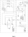
- Ethanol in the raw material tank area enters the ethanol preheater 101 to be heated, then enters the ethanol evaporation tank 102, and is heated to be evaporated in the ethanol evaporators 108, 109.
- Ethanol steam evaporated from the ethanol evaporation tank 102 is fed into the reactor for a reaction after being heated by the ethanol superheater 103.
- a high-temperature reaction gas from the third reactor 107 enters the first gas-liquid separation tank 110 after superheating the ethanol steam, vaporizing the liquid phase raw material of ethanol and preheating the liquid phase raw material of ethanol in sequence, and then the gas is fed into the quenching compression system after gas-liquid separation.
- a gas phase of the first gas-liquid separation tank After a gas phase of the first gas-liquid separation tank, a gas phase of a degassing tank and a gas exhausted from the drying towers enter the quenching tower 113, an overhead gas of the quenching tower enters the second gas-liquid separation tank 123 after being heated.
- Tower kettle fluid of the quenching tower are fed into the evaporation tower feed preheater 117 to be heated, and then enter the evaporation tower 119. After heating the feed stream of the evaporation tower and the overhead gas of the quenching tower in sequence, tower bottoms in the evaporation tower enter the process water tank 122 after being cooled by the evaporation tower bottom cooler 121.
- a gas exhausted from the second gas-liquid separation tank 123 enters the alkaline washing tower 126 after being compressed and cooled, and a gas exhausted from the top of the tower enters the third gas-liquid separation tank 129 after being cooled by the products of ethylene through the crude ethylene cooler 128.
- a gas phase separated from the third gas-liquid separation tank 129 is fed into the drying towers to be dehydrated, and the dried ethylene after dehydration is fed into the ethylene purification and propylene refrigeration cycle system.
- Dried crude ethylene from the molecular sieve drying system is fed into the ethylene chiller 144 to be recooled after being cooled by the ethylene precooler 142, and then enters the demethanizing tower 145.
- the overhead gas of the demethanizing tower is fed into the fuel gas tank 156 after being cooled in the demethanizing tower condenser 147.
- Ethylene produced from the tower kettle is fed into the purification tower 149, and the products of ethylene produced from the top of the purification tower enter the ethylene reflux tank 152 after being cooled in the purification tower condenser 151.
- a part of products of ethylene serving as circulating ethylene are used as a cold source of the demethanizing tower condenser 147 and the ethylene cooler 155, and then are fed into the drying towers to serve as a desorbed gas.
- the rest products of ethylene are fed into an ethylene buffer tank 153.
- Part of ethylene in the ethylene buffer tank 153 is fed back to the top of the purification tower as reflux, and after recycling of cold energy from the rest of ethylene by the ethylene precooler 142 and the crude ethylene cooler 128, the rest of ethylene is discharged out of the boundary region as the products of ethylene after being heated by hot propylene through the product ethylene heater 157.
- the tower bottoms of the evaporation tower serve as a heat exchange medium for the evaporation tower feed preheater and the quenching tower overhead gas heater for heat recycling.
- the cold energy of the products of ethylene is recycled by the ethylene precooler and the crude ethylene cooler, and hot propylene is introduced as a heating stream, thereby avoiding cooling of the hot propylene with cooling water and fully achieving internal cycling of the propylene to reduce introduction of external heating steam.
- heat exchange in the system is disposed rationally to reduce the usage amount of a utility medium in the process of preparing ethylene by ethanol dehydration.
- the energy consumption is reduced by about 48% on the premise of meeting the separation requirements.
- each stream of heat is fully utilized in the present invention, and the heat exchange in the system is disposed rationally to reduce the energy consumption greatly, decrease the equipment investments significantly, and reduce the ethylene production cost.
- a tube pass inlet of an ethanol preheater is connected with a raw material tank area; a shell pass inlet of the ethanol preheater is connected with a shell pass outlet of an ethanol evaporator; a tube pass outlet of the ethanol preheater is connected with an inlet of an ethanol evaporation tank; a shell pass outlet of the ethanol preheater is connected with an inlet of a first gas-liquid separation tank; a tube pass inlet of the ethanol evaporator is connected with an outlet in aat bottom of the ethanol evaporation tank; a shell pass inlet of the ethanol evaporator is connected with a shell pass outlet of an ethanol superheater; a tube pass outlet of the ethanol evaporator is connected with an inlet in a right side of the ethanol evaporation tank; a tube
- an outlet of a tower kettle of an evaporation tower is connected with a shell pass inlet of an evaporation tower feed preheater; an outlet of a tower kettle of a quenching tower is connected with a tube pass inlet of the evaporation tower feed preheater; a tube pass outlet of the evaporation tower feed preheater is connected with an inlet in at a top of the evaporation tower; a shell pass outlet of the evaporation tower feed preheater is connected with a shell pass inlet of a quenching tower overhead gas heater; an overhead steam outlet of the quenching tower is connected with a tube pass inlet of the quenching tower overhead gas heater; a tube pass outlet of the quenching tower overhead gas heater is connected with an inlet of a second gas-liquid separation tank; and a shell pass outlet of the quenching tower overhead gas heater is connected with an inlet of an evaporation tower bottom cooler.
- an overhead steam outlet of an alkaline washing tower is connected with a shell pass inlet of a crude ethylene cooler; a tube pass outlet of an ethylene precooler is connected with a tube pass inlet of the crude ethylene cooler; a shell pass outlet of the crude ethylene cooler is connected with an inlet of a third gas-liquid separation tank; a tube pass outlet of the crude ethylene cooler is connected with a tube pass inlet of a product ethylene heater; in a molecular sieve drying system, a shell pass inlet of a circulating ethylene preheater is connected with a shell pass outlet of an evaporation tower reboiler; a tube pass inlet of the circulating ethylene preheater is connected with a tube pass outlet of a propylene cooler; a tube pass outlet of the circulating ethylene preheater is connected with inlets of drying towers; a shell pass outlet of the circulating ethylene preheater is connected with an inlet of a steam condensate
- the present invention provides a production process for preparing ethylene by ethanol dehydration, and the specific implementation is as follows:
- Ethanol in a raw material tank area enters an ethanol preheater 101 to be heated to 135°C-140°C by a high-temperature dehydration reaction gas, then enters an ethanol evaporation tank 102, and is heated to be evaporated in ethanol evaporators 108, 109.
- a heating medium in the ethanol evaporator 108 is the high-temperature dehydration reaction gas.
- Ethanol steam evaporated from the ethanol evaporation tank 102 is divided into three streams to be fed into a reactor for a reaction after being heated to 324°C-327°C by the high-temperature dehydration reaction gas through an ethanol superheater 103.
- a high-temperature reaction gas from a third reactor 107 enters a first gas-liquid separation tank 110 after its heat is recovered by the ethanol superheater 103, the ethanol evaporator 108 and the ethanol preheater 101 in sequence.
- a separated liquid phase therefrom is fed into an evaporation tower 119 by a separation tank discharge pump 111, and a gas phase is fed into a quenching tower 113 after being cooled.
- an overhead gas of the quenching tower enters a second gas-liquid separation tank 123 after being heated by tower bottoms of the evaporation tower through a quenching tower overhead gas heater 120.
- the tower bottoms of the quenching tower are fed into an evaporation tower feed preheater 117 to be heated to 110°C-114°C by the tower bottoms of the evaporation tower, and then enter the evaporation tower 119. Steam produced from the top of the evaporation tower returns to a dehydration reaction section as diluted steam.
- the tower bottoms After heat of the tower bottoms in the evaporation tower are recovered by the evaporation tower feed preheater 117 and the quenching tower overhead gas heater 120, the tower bottoms enter a process water tank 122 after being cooled by an evaporation tower bottom cooler 121.
- a gas exhausted from the second gas-liquid separation tank 123 enters an alkaline washing tower 126 after being compressed and cooled, and a gas exhausted from the top of the tower enters a third gas-liquid separation tank 129 after being cooled to 18°C-22°C by low-temperature products of ethylene through a crude ethylene cooler 128.
- a gas phase separated from the third gas-liquid separation tank 129 is fed into the drying towers to be dehydrated, and the dried ethylene after dehydration is fed into a demethanizing tower 145 and a purification tower 149 to be refined at low temperature.
- Dried crude ethylene from the molecular sieve drying system is fed into an ethylene chiller 144 to be recooled by low-temperature propylene after being cooled to -32°C to -28°C by the liquid phase products of ethylene through an ethylene precooler 142, and then enters the demethanizing tower 145 after being cooled to -40°C to -35°C.
- the overhead gas of the demethanizing tower is fed into a heating furnace 104 as a fuel gas after being cooled to -68°C to -64°C by decompressed circulating ethylene in a demethanizing tower condenser 147 and vaporized in a fuel gas tank 156.
- Ethylene produced in the tower kettle is fed into a purification tower 149, and the products of ethylene produced from the top of the purification tower enter an ethylene reflux tank 152 after being cooled to -36°C to -34°C by low-temperature propylene through a purification tower condenser 151.
- a part of products of ethylene, serving as the circulating ethylene, are used as a cold source of the demethanizing tower condenser 147 and a propylene cooler 155, and then are fed into the drying towers to serve as a desorbed gas.
- the rest products of ethylene are fed into an ethylene buffer tank 153.
- Part of ethylene in the ethylene buffer tank is fed back to the top of the purification tower as reflux, and after cold energy is recycled from the rest of ethylene by the ethylene precooler 142 and the crude ethylene cooler 128, the rest of ethylene is discharged out of the boundary region as the products of ethylene after being heated to 23°C-26°C by hot propylene through a product ethylene heater 157.
- a demethanizing tower reboiler 146 and a purification tower reboiler 150 are heated by the hot propylene, and resulting propylene condensates are fed into a propylene collection tank 159.
- the device involved in the above technical scheme includes an ethanol preheater 101, an ethanol superheater 103, a heating furnace 104, a third reactor 107, an ethanol evaporator 108, a first gas-liquid separation tank 110, an evaporation tower feed preheater 112, a quenching tower 113, an evaporation tower 119, a quenching tower overhead gas heater 120, an evaporation tower bottom cooler 121, a process water tank 122, a second gas-liquid separation tank 123, an alkaline washing tower 126, a crude ethylene cooler 128, a third gas-liquid separation tank 129, drying towers 130-133, a circulating ethylene preheater 136, a steam condensate flash tank 141, an ethylene precooler 142, an ethylene chiller 144, a demethanizing tower 145, a demethanizing tower reboiler 146, a demethanizing tower condenser 147, a pur
- Ethanol in a raw material tank area enters an ethanol preheater 101 to be heated to 135°C by a high temperature dehydration reaction gas, then enters an ethanol evaporation tank 102, and is heated to be evaporated in ethanol evaporators 108, 109.
- a heating medium in the ethanol evaporator 108 is the high temperature dehydration reaction gas.
- Ethanol steam evaporated from the ethanol evaporation tank 102 is divided into three streams to be fed into the reactor for a reaction after being heated to 324°C by the high temperature dehydration reaction gas through an ethanol superheater 103.
- a high-temperature reaction gas from a third reactor 107 enters a first gas-liquid separation tank 110 after its heat is recovered by the ethanol superheater 103, the ethanol evaporator 108 and the ethanol preheater 101 in sequence.
- a separated liquid phase therefrom is fed into an evaporation tower 119 by a separation tank discharge pump 111, and a gas phase is fed into a quenching tower 113 after being cooled.
- a gas phase of the first gas-liquid separation tank After a gas phase of the first gas-liquid separation tank, a gas phase of a degassing tank and gas exhausted from the drying towers enter the quenching tower 113, an overhead gas of the quenching tower enters a second gas-liquid separation tank 123 after being heated by the tower bottoms of the evaporation tower through a quenching tower overhead gas heater 120.
- the tower bottoms of the quenching tower are fed into an evaporation tower feed preheater 117 to be heated to 110°C by the tower bottoms of the evaporation tower, and then enter the evaporation tower 119. Steam produced from the top of the evaporation tower returns to a dehydration reaction section as diluted steam.
- the tower bottoms After heat of the tower bottoms in the evaporation tower are recovered by the evaporation tower feed preheater 117 and the quenching tower overhead gas heater 120, the tower bottoms enter a process water tank 122 after being cooled by an evaporation tower bottom cooler 121.
- a gas exhausted from the second gas-liquid separation tank 123 enters the alkaline washing tower 126 after being compressed and cooled, and a gas exhausted from the top of the tower enters a third gas-liquid separation tank 129 after being cooled to 18°C by low-temperature products of ethylene through a crude ethylene cooler 128.
- a gas phase separated from the third gas-liquid separation tank 129 is fed into the drying towers to be dehydrated, and the dried ethylene after dehydration is fed into a demethanizing tower 145 and a purification tower 149 to be refined at low temperature.
- Dried crude ethylene from the molecular sieve drying system is fed into an ethylene chiller 144 to be recooled by low-temperature propylene after being cooled to -32°C by the liquid phase products of ethylene through an ethylene precooler 142, and then enters the demethanizing tower 145 after being cooled to -40°C.
- the overhead gas of the demethanizing tower is fed into a heating furnace 104 as a fuel gas after being cooled to -68°C by decompressed circulating ethylene in a demethanizing tower condenser 147 and vaporized in a fuel gas tank 156.
- Ethylene produced in the tower kettle is fed into the purification tower 149, and the products of ethylene produced from the top of the purification tower enter an ethylene reflux tank 152 after being cooled to -36°C by the low-temperature propylene through a purification tower condenser 151.
- a part of products of ethylene, serving as the circulating ethylene, are used as a cold source of a demethanizing tower condenser 147 and a propylene cooler 155, and then are fed into the drying towers to serve as a desorbed gas.
- the rest products of ethylene are fed into an ethylene buffer tank 153.
- Part of ethylene in the ethylene buffer tank is fed back to the top of the purification tower as reflux, and after cold energy is recycled from the rest of ethylene through the ethylene precooler 142 and the crude ethylene cooler 128, the rest of ethylene is discharged out of the boundary region as the products of ethylene after being heated to 23°C by hot propylene through a product ethylene heater 157.
- a demethanizing tower reboiler 146 and a purification tower reboiler 150 are heated by hot propylene, and resulting propylene condensates are fed into a propylene collection tank 159.
- Ethanol in a raw material tank area enters an ethanol preheater 101 to be heated to 140°C by a high temperature dehydration reaction gas, then enters an ethanol evaporation tank 102, and is heated to be evaporated in ethanol evaporators 108, 109.
- a heating medium in the ethanol evaporator 108 is the high temperature dehydration reaction gas.
- Ethanol steam evaporated from the ethanol evaporation tank 102 is divided into three streams to be fed into the reactor for a reaction after being heated to 327°C by the high temperature dehydration reaction gas through an ethanol superheater 103.
- a high-temperature reaction gas from a third reactor 107 enters a first gas-liquid separation tank 110 after its heat is recovered by the ethanol superheater 103, the ethanol evaporator 108 and the ethanol preheater 101 in sequence.
- a separated liquid phase therefrom is fed into an evaporation tower 119 by a separation tank discharge pump 111, and a gas phase is fed into a quenching tower 113 after being cooled.
- a gas phase of the first gas-liquid separation tank After a gas phase of the first gas-liquid separation tank, a gas phase of a degassing tank and gas exhausted from drying towers enter a quenching tower 113, an overhead gas of the quenching tower enters a second gas-liquid separation tank 123 after being heated by the tower bottoms of the evaporation tower through a quenching tower overhead gas heater 120.
- the tower bottoms of the quenching tower are fed into an evaporation tower feed preheater 117 to be heated to 114°C by the tower bottoms of the evaporation tower, and then enter the evaporation tower 119. Steam produced from the top of the evaporation tower returns to a dehydration reaction section as diluted steam.
- the tower bottoms After heat of the tower bottoms in the evaporation tower are recovered by the evaporation tower feed preheater 117 and the quenching tower overhead gas heater 120, the tower bottoms enter a process water tank 122 after being cooled by an evaporation tower bottom cooler 121.
- a gas exhausted from a second gas-liquid separation tank 123 enters an alkaline washing tower 126 after being compressed and cooled, and a gas exhausted from the top of the tower enters a third gas-liquid separation tank 129 after being cooled to 22°C by low-temperature products of ethylene through a crude ethylene cooler 128.
- a gas phase separated from the third gas-liquid separation tank 129 is fed into the drying towers to be dehydrated, and the dried ethylene after dehydration is fed into a demethanizing tower 145 and a purification tower 149 to be refined at low temperature.
- Dried crude ethylene from the molecular sieve drying system is fed into an ethylene chiller 144 to be recooled by low-temperature propylene after being cooled to -28°C by the liquid phase products of ethylene through an ethylene precooler 142, and then enters a demethanizing tower 145 after being cooled to -35°C.
- the overhead gas of the demethanizing tower is fed into a heating furnace 104 as a fuel gas after being cooled to -64°C by decompressed circulating ethylene in a demethanizing tower condenser 147 and vaporized in a fuel gas tank 156.
- Ethylene produced in the tower kettle is fed into the purification tower 149, and the products of ethylene produced from the top of the purification tower enter an ethylene reflux tank 152 after being cooled to -34°C by low-temperature propylene through a purification tower condenser 151.
- a part of products of ethylene, serving as the circulating ethylene, are used as a cold source of the demethanizing tower condenser 147 and a propylene cooler 155, and then are fed into the drying towers to serve as a desorbed gas.
- the rest products of ethylene are fed into an ethylene buffer tank 153.
- Part of ethylene in the ethylene buffer tank is fed back to the top of the purification tower as reflux, and after cold energy of the rest of ethylene is recovered by the ethylene precooler 142 and a crude ethylene cooler 128, the rest of ethylene is discharged out of the boundary region as the products of ethylene after being heated to 26°C by hot propylene through a product ethylene heater 157.
- a demethanizing tower reboiler 146 and a purification tower reboiler 150 are heated by hot propylene, and resulting propylene condensates are fed into a propylene collection tank 159.
- Ethanol in a raw material tank area enters an ethanol preheater 101 to be heated to 136°C by a high temperature dehydration reaction gas, then enters an ethanol evaporation tank 102, and is heated to be evaporated in ethanol evaporators 108 and 109.
- a heating medium in the ethanol evaporator 108 is the high temperature dehydration reaction gas.
- Ethanol steam evaporated from the ethanol evaporation tank 102 is divided into three streams to be fed into the reactor for a reaction after being heated to 325°C by the high temperature dehydration reaction gas through an ethanol superheater 103.
- a high-temperature reaction gas from a third reactor 107 enters a first gas-liquid separation tank 110 after its heat is recovered by the ethanol superheater 103, the ethanol evaporator 108 and the ethanol preheater 101 in sequence.
- a separated liquid phase therefrom is fed into an evaporation tower 119 by a separation tank discharge pump 111, and a gas phase is fed into a quenching tower 113 after being cooled.
- a gas phase of the first gas-liquid separation tank After a gas phase of the first gas-liquid separation tank, a gas phase of a degassing tank and gas exhausted from drying towers enter the quenching tower 113, an overhead gas of the quenching tower enters a second gas-liquid separation tank 123 after being heated by the tower bottoms of the evaporation tower through a quenching tower overhead gas heater 120.
- the tower bottoms of the quenching tower are fed into an evaporation tower feed preheater 117 to be heated to 112°C by the tower bottoms of the evaporation tower, and then enter the evaporation tower 119. Steam produced from the top of the evaporation tower returns to a dehydration reaction section as diluted steam.
- the tower bottoms After heat of the tower bottoms in the evaporation tower are recovered by the evaporation tower feed preheater 117 and the quenching tower overhead gas heater 120, the tower bottoms enter a process water tank 122 after being cooled by an evaporation tower bottom cooler 121.
- a gas exhausted from a second gas-liquid separation tank 123 enters an alkaline washing tower 126 after being compressed and cooled, and a gas exhausted from the top of the tower enters a third gas-liquid separation tank 129 after being cooled to 20°C by low-temperature products of ethylene through a crude ethylene cooler 128.
- a gas phase separated from the third gas-liquid separation tank 129 is fed into the drying towers to be dehydrated, and the dried ethylene after dehydration is fed into a demethanizing tower 145 and a purification tower 149 to be refined at low temperature.
- Dried crude ethylene from the molecular sieve drying system is fed into an ethylene chiller 144 to be recooled by low-temperature propylene after being cooled to -30°C by the liquid phase products of ethylene through an ethylene precooler 142, and then enters the demethanizing tower 145 after being cooled to -38°C.
- the overhead gas of the demethanizing tower is fed into a heating furnace 104 as a fuel gas after being cooled to -65°C by circulating ethylene in a demethanizing tower condenser 147 and vaporized in a fuel gas tank 156.
- Ethylene produced in the tower kettle is fed into the purification tower 149, and the products of ethylene produced from the top of the purification tower enter an ethylene reflux tank 152 after being cooled to -35°C by low-temperature propylene through a purification tower condenser 151.
- a part of products of ethylene, serving as the circulating ethylene, are used as a cold source of the demethanizing tower condenser 147 and a propylene cooler 155, and then are fed into the drying towers to serve as a desorbed gas.
- the rest products of ethylene are fed into an ethylene buffer tank 153.
- Part of ethylene in the ethylene buffer tank is fed back to the top of the purification tower as reflux, and after cold energy of the rest of ethylene is recovered by the ethylene precooler 142 and the crude ethylene cooler 128, the rest of ethylene is discharged out of the boundary region as the products of ethylene after being heated to 25°C by hot propylene through a product ethylene heater 157.
- a demethanizing tower reboiler 146 and a purification tower reboiler 150 are heated by hot propylene, and resulting propylene condensates are fed into a propylene collection tank 159.
- the present invention has the beneficial technical effects that, through heat exchange among different materials, heat exchange in the system is disposed rationally to reduce the usage amount of a utility medium in the process of preparing ethylene by ethanol dehydration. On the premise of meeting the separation requirements, the energy consumption is reduced greatly, and the equipment investment and the ethylene production cost are decreased.
Landscapes
- Chemical & Material Sciences (AREA)
- Organic Chemistry (AREA)
- Engineering & Computer Science (AREA)
- Water Supply & Treatment (AREA)
- Oil, Petroleum & Natural Gas (AREA)
- Analytical Chemistry (AREA)
- Chemical Kinetics & Catalysis (AREA)
- Inorganic Chemistry (AREA)
- General Chemical & Material Sciences (AREA)
- Materials Engineering (AREA)
- Thermal Sciences (AREA)
- Combustion & Propulsion (AREA)
- Physics & Mathematics (AREA)
- Organic Low-Molecular-Weight Compounds And Preparation Thereof (AREA)
- Vaporization, Distillation, Condensation, Sublimation, And Cold Traps (AREA)
Claims (8)
- Thermisches Kopplungsverfahren zum Herstellen von Ethylen durch Ethanoldehydratisierung, dadurch gekennzeichnet, dass das Verfahren ein Ethanoldehydratisierung-Reaktionssystem, ein Quench-Kompressionssystem, ein alkalisches Waschsystem, ein Molekularsieb-Trocknungssystem und ein Ethylenaufreinigungs- und Propylenkühlkreislaufsystem beinhaltet; wobei Ethanoldehydratisierung-Reaktionsprodukte in dem Ethanoldehydratisierung-Reaktionssystem als Wärmequelle zum Vorerhitzen, Verdampfen und Überhitzen eines Rohmaterial von Ethanol dient; Turmkesselfluid eines Verdampfungsturms in dem Quench-Kompressionssystem als Wärmequelle zum Vorerhitzen eines Zustroms des Verdampfungsturms und Erhitzen eines Kopfgases eines Quenchturms dient; Ethylenprodukte in dem alkalischen Waschsystem als Kältequelle zum Kühlen von Rohethylen dienen; Turmkesselfluid des Verdampfungsturms in dem Molekularsieb-Trocknungssystem als Wärmequelle zum Vorerhitzen von zirkulierendem Ethylen dient; die Ethylenprodukte in dem Ethylenaufreinigungs- und Propylenkühlkreislaufsystem als Kältequelle zum Vorkühlen von getrocknetem Ethylen dienen; das zirkulierende Ethylen als Kältequelle zum Kühlen eines Kopfgases eines Entmethanisierungsturm und Kühlen von Propylen dient; Niedertemperaturpropylen als Kältequelle zum Kühlen eines Kopfgases eines Aufreinigungsturms und weiteren Kühlen des Ethylens dient; und warmes Propylen als Wärmequelle zum Erhitzen der Turmböden des Entmethanisierungsturms, der Turmböden des Aufreinigungsturms und der Ethylenprodukte dient.
- Thermisches Kopplungsverfahren zum Herstellen von Ethylen durch Ethanoldehydratisierung nach Anspruch 1, dadurch gekennzeichnet, dass das Ethanoldehydratisierung-Reaktionssystem Ethanolvorerhitzer, Ethanolverdampfer, einen Ethanolverdampfungstank, einen Ethanolüberhitzer, einen ersten Gas-Flüssigkeit-Abscheidungstank, einen dritten Reaktor und einen Erhitzungsofen beinhaltet; das Quench-Kompressionssystem einen Verdampfungsturm, einen Verdampfungsturm-Zustromvorerhitzer, einen Verdampfungsturm-Umlaufverdampfer, einen Quenchturm, a Quenchturm-Kopfgaserhitzer, einen zweiten Gas-Flüssigkeit-Abscheidungstank, einen Verdampfungsturm-Bodenkühler und einen Prozesswassertank beinhaltet; die Ethanoldehydratisierung-Reaktionsprodukte in den Ethanolüberhitzer eintreten, um Ethanoldampf zu überhitzen; die gekühlten Reaktionsprodukte in den Ethanolverdampfer eintreten, um das Flüssigphasenrohmaterial von Ethylen zu verdampfen, und dann die Reaktionsprodukte in den Ethanolvorerhitzer eintreten, um das Flüssigphasenrohmaterial von Ethylen vorzuerhitzen; die gekühlten Ethanoldehydratisierung-Reaktionsprodukte wiederholt in den ersten Gas-Flüssigkeit-Abscheidungstank' zugeführt werden; die Turmböden des Verdampfungsturms in den Verdampfungsturm-Zustromvorerhitzer eintreten, um den Zustrom des Verdampfungsturms vorzuerhitzen, die gekühlten Turmböden des Verdampfungsturms in den Quenchturm-Kopfgaserhitzer eintreten, um das Kopfgas des Quenchturms zu erhitzen, und dann Turmböden des Verdampfungsturms in den Prozesswassertank zugeführt werden; und die Verdampfungsturm-Umlaufverdampferkondensate dem Molekularsieb-Trocknungssystem zugeführt werden.
- Thermisches Kopplungsverfahren zum Herstellen von Ethylen durch Ethanoldehydratisierung nach Anspruch 1, dadurch gekennzeichnet, dass das alkalische Waschsystem einen alkalischen Waschturm, einen Rohethylenkühler und einen dritten Gas-Flüssigkeit-Abscheidungstank beinhaltet; das Molekularsieb-Trocknungssystem Trocknungstürme, einen Vorerhitzer für zirkulierendes Ethylen und einen Dampfkondensat-Entspannungstank beinhaltet; die Ethylenprodukte aus dem Ethylenaufreinigungs- und Propylenkühlkreislaufsystem in den Rohethylenkühler eintreten, um Rohethylen zu kühlen, das in dem alkalischen Waschturm erzeugt wird, und dann die Ethylenprodukte einem Ethylenprodukterhitzer zugeführt werden; und die Verdampfungsturm-Umlaufverdampferkondensate aus dem Quench-Kompressionssystem in den Vorerhitzer für zirkulierendes Ethylen eintreten, um das zirkulierende Ethylen vorzuerhitzen, und die gekühlten Umlaufverdampferkondensate dem Dampfkondensat-Entspannungstank zugeführt werden.
- Thermisches Kopplungsverfahren zum Herstellen von Ethylen durch Ethanoldehydratisierung nach Anspruch 1, dadurch gekennzeichnet, dass das Ethylenaufreinigungs- und Propylenkühlkreislaufsystem, einen Ethylenvorkühler, einen Ethylenkühlapparat, einen Entmethanisierungsturm, einen Entmethanisierungsturmkondensator, einen Entmethanisierungsturm-Umlaufverdampfer, einen Aufreinigungsturm, einen Aufreinigungsturmkondensator, einen Aufreinigungsturm-Umlaufverdampfer, einen Ethylenrefluxtank, einen Propylenkühler, einen Heizgastank, einen Ethylenprodukterhitzer, einen primären Propylenentspannungstank, einen Propylenauffangtank, und einen sekundären Propylenverdichter beinhaltet; das zirkulierende Ethylen in den Entmethanisierungsturmkondensator eintritt, um das Kopfgas des Entmethanisierungsturms zu kühlen, das zirkulierende Ethylen dem Propylenkühler zugeführt wird, um Propylen zu kühlen, und dann das zirkulierende Ethylen dem Molekularsieb-Trocknungssystem zugeführt wird; die Ethylenprodukte in den Ethylenvorkühler eintreten, um das getrocknete Rohethylen zu kühlen, und die erhitzten Ethylenprodukte dem alkalischen Waschsystem zugeführt werden, und dann nach Erhitzen aus einer Grenzregion ausgetragen werden; das Niedertemperaturpropylen in den Aufreinigungsturmkondensator eintritt, um das Kopfgas des Aufreinigungsturms zu kühlen, das erhitzte Niedertemperaturpropylen dem Ethylenkühlapparat zugeführt wird, um das Ethylen weiter zu kühlen, und dann das Niedertemperaturpropylen dem primären Propylenentspannungstank zugeführt wird; und heißes Propylen von der Außenseite der Grenzregion in den Entmethanisierungsturm-Umlaufverdampfer, den Aufreinigungsturm-Umlaufverdampfer bzw. den Ethylenprodukterhitzer eintritt, um die Turmböden des Entmethanisierungsturms, die Turmböden des Aufreinigungsturms und die Ethylenprodukte zu erhitzen, und das gekühlte Propylen dem Propylenauffangtank zugeführt wird.
- Vorrichtung zum Erreichen des thermischen Kopplungsverfahrens zum Herstellen von Ethylen durch Ethanoldehydratisierung nach Anspruch 1, dadurch gekennzeichnet, dass in dem Ethanoldehydratisierung-Reaktionssystem ein Rohrdurchgangeinlass des Ethanolvorerhitzers mit einer Rohmaterialtankfläche verbunden ist; ein Manteldurchgangeinlass des Ethanolvorerhitzers mit einem Manteldurchgangauslass des Ethanolverdampfers verbunden ist; ein Rohrdurchgangauslass des Ethanolvorerhitzers mit einem Einlass des Ethanolverdampfungstanks verbunden ist; ein Manteldurchgangauslass des Ethanolvorerhitzers mit einem Einlass des ersten Gas-Flüssigkeit-Abscheidungstanks verbunden ist; ein Rohrdurchgangeinlass des Ethanolverdampfers mit einem Auslass an einem Boden des Ethanolverdampfungstanks verbunden ist; ein Manteldurchgangeinlass des Ethanolverdampfers mit einem Manteldurchgangauslass des Ethanolüberhitzers verbunden ist; ein Rohrdurchgangauslass des Ethanolverdampfers mit einem Einlass auf einer rechten Seite des Ethanolverdampfungstanks verbunden ist; ein Rohrdurchgangeinlass des Ethanolüberhitzers mit einem Auslass an einer Oberseite des Ethanolverdampfungstanks verbunden ist; ein Manteldurchgangeinlass des Ethanolüberhitzers mit einem Auslass des dritten Reaktors verbunden ist; ein Rohrdurchgangauslass des Ethanolüberhitzers mit einem Einlass des Erhitzungsofens verbunden ist; in dem Quench-Kompressionssystem ein Auslass des Turmkessels des Verdampfungsturms mit einem Manteldurchgangeinlass des Verdampfungsturm-Zustromvorerhitzers verbunden ist; ein Auslass des Turmkessels des Quenchturms mit einem Rohrdurchgangeinlass des Verdampfungsturm-Zustromvorerhitzers verbunden ist; ein Rohrdurchgangauslass des Verdampfungsturm-Zustromvorerhitzers mit einem Einlass an einer Oberseite des Verdampfungsturms verbunden ist; ein Manteldurchgangauslass des Verdampfungsturm-Zustromvorerhitzers mit einem Manteldurchgangeinlass des Quenchturms-Kopfgaserhitzer verbunden ist; ein Kopfdampfauslass des Quenchturms mit einem Rohrdurchgangeinlass des Quenchturms-Kopfgaserhitzers verbunden ist; ein Rohrdurchgangauslass des Quenchturms-Kopfgaserhitzers mit einem Einlass des zweiten Gas-Flüssigkeit-Abscheidungstanks verbunden ist; und ein Manteldurchgangauslass des Quenchturms-Kopfgaserhitzers mit einem Einlass des Verdampfungsturm-Bodenkühlers verbunden ist.
- Vorrichtung zum Erreichen des thermischen Kopplungsverfahrens zum Herstellen von Ethylen durch Ethanoldehydratisierung nach Anspruch 1, dadurch gekennzeichnet, dass in dem alkalischen Waschsystem ein Kopfdampfauslass des alkalischen Waschturms mit einem Manteldurchgangeinlass des Rohethylenkühlers verbunden ist; ein Rohrdurchgangauslass des Ethylenvorkühlers mit einem Rohrdurchgangeinlass des Rohethylenkühlers verbunden ist; ein Manteldurchgangauslass des Rohethylenkühlers mit einem Einlass des dritten Gas-Flüssigkeit-Abscheidungstanks verbunden ist; ein Rohrdurchgangauslass des Rohethylenkühlers mit einem Rohrdurchgangeinlass des Ethylenprodukterhitzers verbunden ist; in dem Molekularsieb-Trocknungssystem ein Manteldurchgangeinlass des Vorerhitzers für zirkulierendes Ethylen mit einem Manteldurchgangauslass des Verdampfungsturm-Umlaufverdampfers verbunden ist; ein Rohrdurchgangeinlass des Vorerhitzers für zirkulierendes Ethylen mit einem Rohrdurchgangauslass des Propylenkühlers verbunden ist; ein Rohrdurchgangauslass des Vorerhitzers für zirkulierendes Ethylen mit Einlässen der Trocknungstürme verbunden ist; und ein Manteldurchgangauslass des Vorerhitzers für zirkulierendes Ethylen mit einem Einlass des Dampfkondensat-Entspannungstanks verbunden ist.
- Vorrichtung zum Erreichen des thermischen Kopplungsverfahrens zum Herstellen von Ethylen durch Ethanoldehydratisierung nach Anspruch 1, dadurch gekennzeichnet, dass in dem Ethylenaufreinigungs- und Propylenkühlkreislaufsystem ein Manteldurchgangeinlass des Ethylenvorkühlers mit Auslässen der Trocknungstürme verbunden ist; ein Rohrdurchgangeinlass des Ethylenvorkühlers mit einem Auslass des Ethylenzwischenspeichertank verbunden ist; ein Manteldurchgangauslass des Ethylenvorkühlers mit einem Manteldurchgangeinlass des Ethylenkühlapparats verbunden ist; ein Rohrdurchgangeinlass des Ethylenkühlapparats mit einem Auslass des sekundären Propylenverdichters verbunden ist; ein Rohrdurchgangauslass des Ethylenkühlapparats mit einem Einlass eines primären Propylenabscheidungstank verbunden ist; ein Manteldurchgangauslass des Ethylenkühlapparats mit einem Einlass des Entmethanisierungsturms verbunden ist; ein Kopfdampfauslass des Entmethanisierungsturms mit einem Manteldurchgangeinlass des Entmethanisierungsturmkondensators verbunden ist; ein Rohrdurchgangeinlass des Entmethanisierungsturmkondensators mit einem Auslass des Ethylenrefluxtanks verbunden ist; ein Rohrdurchgangauslass des Entmethanisierungsturmkondensators mit einem Rohrdurchgangeinlass des Propylenkühlers verbunden ist; ein Manteldurchgangauslass des Entmethanisierungsturmkondensators mit einem Einlass des Heizgastanks verbunden ist; ein Auslass des Turmkessels des Entmethanisierungsturms mit einem Rohrdurchgangeinlass des Entmethanisierungsturm-Umlaufverdampfers verbunden ist; ein Rohrdurchgangauslass des Entmethanisierungsturm-Umlaufverdampfers mit einem Einlass des Turmkessels des Entmethanisierungsturms verbunden ist; ein Manteldurchgangauslass des Entmethanisierungsturm-Umlaufverdampfers mit einem Einlass des Propylenauffangtanks verbunden ist; ein Kopfdampfauslass des Aufreinigungsturms mit einem Manteldurchgangeinlass des Aufreinigungsturmkondensators verbunden ist; ein Rohrdurchgangeinlass des Aufreinigungsturmkondensators mit einem Auslass des sekundären Propylenverdichters verbunden ist; ein Manteldurchgangauslass des Aufreinigungsturmkondensators mit einem Einlass des Ethylenrefluxtank verbunden ist; ein Rohrdurchgangauslass des Aufreinigungsturmkondensators mit einem Einlass des primären Propylenentspannungstanks verbunden ist; ein Auslass des Turmkessels des Aufreinigungsturms mit einem Rohrdurchgangeinlass des Aufreinigungsturm-Umlaufverdampfers verbunden ist; ein Rohrdurchgangauslass des Aufreinigungsturm-Umlaufverdampfers mit einem Einlass des Turmkessels des Aufreinigungsturms verbunden ist; ein Manteldurchgangauslass des Aufreinigungsturms Umlaufverdampfer mit einem Einlass an einer Oberseite des Propylenauffangtanks verbunden ist; ein Manteldurchgangeinlass des Propylenkühlers mit einem Auslass an einer Unterseite des Propylenauffangtanks verbunden ist; ein Manteldurchgangauslass des Propylenkühlers mit einem Einlass des primären Propylenentspannungstanks verbunden ist; und ein Manteldurchgangauslass des Ethylenprodukterhitzers mit einem Einlass an einer Oberseite des Ethylenauffangtanks verbunden ist.
- Vorrichtung zum Erreichen des thermischen Kopplungsverfahrens zum Herstellen von Ethylen durch Ethanoldehydratisierung nach Anspruch 1, dadurch gekennzeichnet, dass alle Wärmetauscher Mantel- und Rohrwärmetauscher sind.
Applications Claiming Priority (1)
| Application Number | Priority Date | Filing Date | Title |
|---|---|---|---|
| CN202211056719.8A CN115322068B (zh) | 2022-08-30 | 2022-08-30 | 乙醇脱水制乙烯热耦合方法及装置 |
Publications (4)
| Publication Number | Publication Date |
|---|---|
| EP4332076A2 EP4332076A2 (de) | 2024-03-06 |
| EP4332076A3 EP4332076A3 (de) | 2024-03-20 |
| EP4332076B1 true EP4332076B1 (de) | 2024-11-27 |
| EP4332076C0 EP4332076C0 (de) | 2024-11-27 |
Family
ID=83928070
Family Applications (1)
| Application Number | Title | Priority Date | Filing Date |
|---|---|---|---|
| EP23180766.0A Active EP4332076B1 (de) | 2022-08-30 | 2023-06-21 | Thermisches kupplungsverfahren zur herstellung von ethylen durch ethanoldehydrierung und vorrichtung dafür |
Country Status (4)
| Country | Link |
|---|---|
| US (1) | US12071387B2 (de) |
| EP (1) | EP4332076B1 (de) |
| JP (1) | JP7545175B2 (de) |
| CN (1) | CN115322068B (de) |
Family Cites Families (13)
| Publication number | Priority date | Publication date | Assignee | Title |
|---|---|---|---|---|
| LU85515A1 (fr) * | 1984-08-28 | 1986-03-11 | Belge Etat | Catalyseurs pour la transformation d'ethanol en ethylene et leur utilisation |
| CN101121624B (zh) * | 2006-08-11 | 2010-09-08 | 中国石油化工股份有限公司 | 乙醇脱水制乙烯的方法 |
| CN101168124A (zh) * | 2006-10-25 | 2008-04-30 | 中国科学院大连化学物理研究所 | 一种乙醇脱水制乙烯催化剂及制备方法 |
| CN101244970B (zh) * | 2007-02-13 | 2012-02-01 | 广东中科天元新能源科技有限公司 | 乙醇制备乙烯的生产装置及工艺 |
| CN103121898B (zh) | 2011-11-18 | 2015-04-08 | 中国石油化工股份有限公司 | 含乙烯产物的分离回收方法 |
| FR2998568B1 (fr) * | 2012-11-27 | 2015-01-23 | IFP Energies Nouvelles | Procede de deshydratation de l'ethanol en ethylene a basse consommation |
| FR3001969B1 (fr) * | 2013-02-12 | 2015-08-21 | IFP Energies Nouvelles | Procede de production d'oxyde d'ethylene a partir d'un flux d'ethanol thermiquement integre |
| FR3001968B1 (fr) * | 2013-02-12 | 2015-02-27 | IFP Energies Nouvelles | Procede de production d'oxyde d'ethylene a partir d'un flux d'ethanol thermo-mecaniquement integre |
| EP2949635A1 (de) * | 2014-05-28 | 2015-12-02 | Linde Aktiengesellschaft | Verfahren zur Herstellung von Produktolefinen durch katalytische Dehydratisierung geeigneter Reaktanden |
| CN106608787B (zh) | 2015-10-22 | 2019-04-12 | 中国石油化工股份有限公司 | 乙醇脱水制乙烯工艺中热量综合利用的方法 |
| FR3089973B1 (fr) * | 2018-12-14 | 2020-12-25 | Ifp Energies Now | Procédé de déshydratation de l'éthanol en éthylène à basse consommation énergétique |
| CN114644540A (zh) * | 2020-12-18 | 2022-06-21 | 中国石油化工股份有限公司 | 一种醇制低碳烯烃的装置和方法 |
| CN113045372B (zh) * | 2021-03-16 | 2022-01-28 | 天津大学 | 乙醇脱水制备乙烯生产工艺及装置 |
-
2022
- 2022-08-30 CN CN202211056719.8A patent/CN115322068B/zh active Active
-
2023
- 2023-06-19 US US18/211,391 patent/US12071387B2/en active Active
- 2023-06-21 EP EP23180766.0A patent/EP4332076B1/de active Active
- 2023-07-18 JP JP2023116887A patent/JP7545175B2/ja active Active
Also Published As
| Publication number | Publication date |
|---|---|
| US20240067583A1 (en) | 2024-02-29 |
| EP4332076A3 (de) | 2024-03-20 |
| US12071387B2 (en) | 2024-08-27 |
| JP2024035093A (ja) | 2024-03-13 |
| CN115322068B (zh) | 2023-03-28 |
| EP4332076C0 (de) | 2024-11-27 |
| EP4332076A2 (de) | 2024-03-06 |
| JP7545175B2 (ja) | 2024-09-04 |
| CN115322068A (zh) | 2022-11-11 |
Similar Documents
| Publication | Publication Date | Title |
|---|---|---|
| CN113045372B (zh) | 乙醇脱水制备乙烯生产工艺及装置 | |
| CN108645119B (zh) | 丙烷脱氢产品气深冷分离装置和方法 | |
| CN101195561B (zh) | 甲醇气相脱水制二甲醚的方法 | |
| CN101244970B (zh) | 乙醇制备乙烯的生产装置及工艺 | |
| CN216536963U (zh) | 一种硫酸烷基化反应产物的分离系统 | |
| CN115317945A (zh) | 烷基化反应产物两塔热耦合与热泵组合分离工艺及分离装置 | |
| CN110591751A (zh) | 一种轻烃回收技术改进工艺 | |
| CN117720397B (zh) | 一种二氧化碳催化加氢制甲醇的工艺和装置 | |
| EP4332076B1 (de) | Thermisches kupplungsverfahren zur herstellung von ethylen durch ethanoldehydrierung und vorrichtung dafür | |
| CN108017501B (zh) | 一种集成吸收制冷的丙烯精馏塔工艺方法 | |
| CN212770584U (zh) | 一种烷基化产物分离系统 | |
| CN109761735A (zh) | 石脑油及丙烷裂解前脱丙烷与pdh耦合的方法 | |
| CN110407658B (zh) | 一种低能耗乙烷裂解气深冷分离工艺方法 | |
| CN210625398U (zh) | 一种低温乙烷的冷量回收利用系统 | |
| CN218046534U (zh) | 一种丙烷脱氢原料纯化、汽化装置 | |
| CN118236715A (zh) | 用于丙烷丙烯分离的热泵精馏装置 | |
| CN101143807A (zh) | 一种采用分离热管型反应器生产二甲醚的方法 | |
| CN113563148B (zh) | 一种集成余热制冷的煤制天然气和甲醇多联产系统及方法 | |
| CN111943800B (zh) | 一种对轻烃进行热裂解生产丙烯及乙烯的方法 | |
| CN214032356U (zh) | 一种节能耐硫变换系统 | |
| CN119113548A (zh) | 一种rtc干气与乙烯装置耦合的方法和系统及乙烯装置的改造 | |
| CN106316800A (zh) | 一种低耗能由甲醇制备二甲醚的方法 | |
| CN101792679B (zh) | 一种阶梯利用低温废水汽化丙烯脱聚合油塔进料的节能方法及装置 | |
| CN206591058U (zh) | 一种甲醇基二甲醚燃料生产与锅炉供热系统 | |
| CN224180276U (zh) | 一种轻烃转化产物分馏装置 |
Legal Events
| Date | Code | Title | Description |
|---|---|---|---|
| PUAI | Public reference made under article 153(3) epc to a published international application that has entered the european phase |
Free format text: ORIGINAL CODE: 0009012 |
|
| STAA | Information on the status of an ep patent application or granted ep patent |
Free format text: STATUS: REQUEST FOR EXAMINATION WAS MADE |
|
| PUAL | Search report despatched |
Free format text: ORIGINAL CODE: 0009013 |
|
| 17P | Request for examination filed |
Effective date: 20230621 |
|
| AK | Designated contracting states |
Kind code of ref document: A2 Designated state(s): AL AT BE BG CH CY CZ DE DK EE ES FI FR GB GR HR HU IE IS IT LI LT LU LV MC ME MK MT NL NO PL PT RO RS SE SI SK SM TR |
|
| AK | Designated contracting states |
Kind code of ref document: A3 Designated state(s): AL AT BE BG CH CY CZ DE DK EE ES FI FR GB GR HR HU IE IS IT LI LT LU LV MC ME MK MT NL NO PL PT RO RS SE SI SK SM TR |
|
| RIC1 | Information provided on ipc code assigned before grant |
Ipc: C07C 11/04 20060101ALI20240214BHEP Ipc: C07C 7/148 20060101ALI20240214BHEP Ipc: C07C 7/13 20060101ALI20240214BHEP Ipc: C07C 7/00 20060101ALI20240214BHEP Ipc: C07C 1/20 20060101AFI20240214BHEP |
|
| GRAP | Despatch of communication of intention to grant a patent |
Free format text: ORIGINAL CODE: EPIDOSNIGR1 |
|
| STAA | Information on the status of an ep patent application or granted ep patent |
Free format text: STATUS: GRANT OF PATENT IS INTENDED |
|
| INTG | Intention to grant announced |
Effective date: 20240910 |
|
| GRAS | Grant fee paid |
Free format text: ORIGINAL CODE: EPIDOSNIGR3 |
|
| GRAA | (expected) grant |
Free format text: ORIGINAL CODE: 0009210 |
|
| STAA | Information on the status of an ep patent application or granted ep patent |
Free format text: STATUS: THE PATENT HAS BEEN GRANTED |
|
| AK | Designated contracting states |
Kind code of ref document: B1 Designated state(s): AL AT BE BG CH CY CZ DE DK EE ES FI FR GB GR HR HU IE IS IT LI LT LU LV MC ME MK MT NL NO PL PT RO RS SE SI SK SM TR |
|
| REG | Reference to a national code |
Ref country code: GB Ref legal event code: FG4D |
|
| REG | Reference to a national code |
Ref country code: CH Ref legal event code: EP |
|
| REG | Reference to a national code |
Ref country code: IE Ref legal event code: FG4D |
|
| REG | Reference to a national code |
Ref country code: DE Ref legal event code: R096 Ref document number: 602023001163 Country of ref document: DE |
|
| U01 | Request for unitary effect filed |
Effective date: 20241216 |
|
| U07 | Unitary effect registered |
Designated state(s): AT BE BG DE DK EE FI FR IT LT LU LV MT NL PT RO SE SI Effective date: 20250110 |
|
| PG25 | Lapsed in a contracting state [announced via postgrant information from national office to epo] |
Ref country code: HR Free format text: LAPSE BECAUSE OF FAILURE TO SUBMIT A TRANSLATION OF THE DESCRIPTION OR TO PAY THE FEE WITHIN THE PRESCRIBED TIME-LIMIT Effective date: 20241127 Ref country code: IS Free format text: LAPSE BECAUSE OF FAILURE TO SUBMIT A TRANSLATION OF THE DESCRIPTION OR TO PAY THE FEE WITHIN THE PRESCRIBED TIME-LIMIT Effective date: 20250327 |
|
| PG25 | Lapsed in a contracting state [announced via postgrant information from national office to epo] |
Ref country code: ES Free format text: LAPSE BECAUSE OF FAILURE TO SUBMIT A TRANSLATION OF THE DESCRIPTION OR TO PAY THE FEE WITHIN THE PRESCRIBED TIME-LIMIT Effective date: 20241127 |
|
| PG25 | Lapsed in a contracting state [announced via postgrant information from national office to epo] |
Ref country code: NO Free format text: LAPSE BECAUSE OF FAILURE TO SUBMIT A TRANSLATION OF THE DESCRIPTION OR TO PAY THE FEE WITHIN THE PRESCRIBED TIME-LIMIT Effective date: 20250227 |
|
| PG25 | Lapsed in a contracting state [announced via postgrant information from national office to epo] |
Ref country code: GR Free format text: LAPSE BECAUSE OF FAILURE TO SUBMIT A TRANSLATION OF THE DESCRIPTION OR TO PAY THE FEE WITHIN THE PRESCRIBED TIME-LIMIT Effective date: 20250228 |
|
| PG25 | Lapsed in a contracting state [announced via postgrant information from national office to epo] |
Ref country code: PL Free format text: LAPSE BECAUSE OF FAILURE TO SUBMIT A TRANSLATION OF THE DESCRIPTION OR TO PAY THE FEE WITHIN THE PRESCRIBED TIME-LIMIT Effective date: 20241127 |
|
| PG25 | Lapsed in a contracting state [announced via postgrant information from national office to epo] |
Ref country code: RS Free format text: LAPSE BECAUSE OF FAILURE TO SUBMIT A TRANSLATION OF THE DESCRIPTION OR TO PAY THE FEE WITHIN THE PRESCRIBED TIME-LIMIT Effective date: 20250227 |
|
| PG25 | Lapsed in a contracting state [announced via postgrant information from national office to epo] |
Ref country code: SM Free format text: LAPSE BECAUSE OF FAILURE TO SUBMIT A TRANSLATION OF THE DESCRIPTION OR TO PAY THE FEE WITHIN THE PRESCRIBED TIME-LIMIT Effective date: 20241127 |
|
| U20 | Renewal fee for the european patent with unitary effect paid |
Year of fee payment: 3 Effective date: 20250610 |
|
| PG25 | Lapsed in a contracting state [announced via postgrant information from national office to epo] |
Ref country code: SK Free format text: LAPSE BECAUSE OF FAILURE TO SUBMIT A TRANSLATION OF THE DESCRIPTION OR TO PAY THE FEE WITHIN THE PRESCRIBED TIME-LIMIT Effective date: 20241127 |
|
| PG25 | Lapsed in a contracting state [announced via postgrant information from national office to epo] |
Ref country code: CZ Free format text: LAPSE BECAUSE OF FAILURE TO SUBMIT A TRANSLATION OF THE DESCRIPTION OR TO PAY THE FEE WITHIN THE PRESCRIBED TIME-LIMIT Effective date: 20241127 |
|
| PLBE | No opposition filed within time limit |
Free format text: ORIGINAL CODE: 0009261 |
|
| STAA | Information on the status of an ep patent application or granted ep patent |
Free format text: STATUS: NO OPPOSITION FILED WITHIN TIME LIMIT |
|
| 26N | No opposition filed |
Effective date: 20250828 |
|
| PG25 | Lapsed in a contracting state [announced via postgrant information from national office to epo] |
Ref country code: MC Free format text: LAPSE BECAUSE OF FAILURE TO SUBMIT A TRANSLATION OF THE DESCRIPTION OR TO PAY THE FEE WITHIN THE PRESCRIBED TIME-LIMIT Effective date: 20241127 |
|
| PG25 | Lapsed in a contracting state [announced via postgrant information from national office to epo] |
Ref country code: IE Free format text: LAPSE BECAUSE OF NON-PAYMENT OF DUE FEES Effective date: 20250621 |