EP4331986A1 - Steuervorrichtung auf basis mindestens eines parameterkriteriums eines flüssigkeitsausstosssystems für ein host-feuerkontrollflugzeug - Google Patents
Steuervorrichtung auf basis mindestens eines parameterkriteriums eines flüssigkeitsausstosssystems für ein host-feuerkontrollflugzeug Download PDFInfo
- Publication number
- EP4331986A1 EP4331986A1 EP23192071.1A EP23192071A EP4331986A1 EP 4331986 A1 EP4331986 A1 EP 4331986A1 EP 23192071 A EP23192071 A EP 23192071A EP 4331986 A1 EP4331986 A1 EP 4331986A1
- Authority
- EP
- European Patent Office
- Prior art keywords
- aircraft
- release
- fluid
- tank
- water
- Prior art date
- Legal status (The legal status is an assumption and is not a legal conclusion. Google has not performed a legal analysis and makes no representation as to the accuracy of the status listed.)
- Granted
Links
Images


Classifications
-
- B—PERFORMING OPERATIONS; TRANSPORTING
- B64—AIRCRAFT; AVIATION; COSMONAUTICS
- B64D—EQUIPMENT FOR FITTING IN OR TO AIRCRAFT; FLIGHT SUITS; PARACHUTES; ARRANGEMENT OR MOUNTING OF POWER PLANTS OR PROPULSION TRANSMISSIONS IN AIRCRAFT
- B64D1/00—Dropping, ejecting, releasing or receiving articles, liquids, or the like, in flight
- B64D1/16—Dropping or releasing powdered, liquid, or gaseous matter, e.g. for fire-fighting
-
- A—HUMAN NECESSITIES
- A62—LIFE-SAVING; FIRE-FIGHTING
- A62C—FIRE-FIGHTING
- A62C3/00—Fire prevention, containment or extinguishing specially adapted for particular objects or places
- A62C3/02—Fire prevention, containment or extinguishing specially adapted for particular objects or places for area conflagrations, e.g. forest fires, subterranean fires
- A62C3/0228—Fire prevention, containment or extinguishing specially adapted for particular objects or places for area conflagrations, e.g. forest fires, subterranean fires with delivery of fire extinguishing material by air or aircraft
- A62C3/0242—Fire prevention, containment or extinguishing specially adapted for particular objects or places for area conflagrations, e.g. forest fires, subterranean fires with delivery of fire extinguishing material by air or aircraft by spraying extinguishants from the aircraft
Definitions
- the present invention relates to a system for storing and releasing fluid and more particularly water or products such as a retardant integrated into a host aircraft making it possible to convert it into a water bomber aircraft used for fighting fires in particular. forests and more particularly a control device for this system.
- the invention applies to all types of aircraft capable of receiving such a system and in particular to civil and military aircraft.
- the present invention aims to propose an improvement in water storage and release systems to limit the quantity of water projected.
- the present invention relates to a device for controlling a fluid storage and release system fitted to a host aircraft comprising a fluid reservoir and at least one tube, characterized in that the control device is connected to at least one valve making it possible to authorize or prohibit the release of water and controls the flow rate of fluid released and the duration of release according to at least one parameterized criterion.
- the quantity of fluid released is adapted to the situation facing the host aircraft and a saving of fluid can be achieved if the entire tank is not necessary.
- the invention provides at least one of the following optional characteristics, taken individually or in combination.
- the fluid storage and release system comprising a fluid release device comprising a closed tank having at least one opening intended to be connected respectively to said tube or tubes for the entry of fluid in a sealed manner into the tank and at least one opening allowing the fluid to be released, said opening(s) being capable of being closed using opening/closing valves (55).
- Said control device controls the opening/closing of a determined number of openings to adjust the quantity of water released according to at least one criterion.
- the device includes a gun equipped with a trigger and a control panel.
- the device includes on the control panel at least one adjustment button per criterion to be entered.
- the device includes a display screen for the criterion(s) to be configured.
- the device includes a calculation processor programmed to calculate the flow rate and release duration based on the data entered and control the valves corresponding to the result obtained.
- valves corresponding to the desired quantity of water released are ordered to open.
- the present invention also relates to the aircraft equipped with a fluid storage and release system comprising a fluid reservoir and at least one tube characterized in that it comprises a control device having one or more of the aforementioned characteristics.
- the invention provides at least one of the following optional characteristics, taken individually or in combination.
- the device is positioned in the aircraft so that the criterion is configured by a pilot and/or co-pilot and/or third man and/or any operator.
- the control device is wirelessly linked to the storage and release system and controlled from the ground.
- the following description refers to an orthonormal reference X, Y, Z (visible on the figures 1 and 2 ) in which the horizontal directions X,Y and vertical Z are defined with reference to an aircraft placed on horizontal ground.
- the three directions X, Y, Z are orthogonal to each other.
- the fuselage of the aircraft extends along a longitudinal direction X.
- the Y direction corresponds to the direction oriented transversely and horizontally with respect to the longitudinal direction
- vertical means parallel to the longitudinal direction, respectively transverse or vertical.
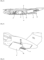
- FIG 1 represents a military aircraft 2 type A400M (registered trademark) intended to be temporarily converted into a water bomber aircraft.
- the aircraft 2 includes a zone 4 offering useful interior free space. It also has a rear door 6 that can open in flight. There figure 1 represents door 6 in the closed position.
- the A400M is taken for illustrative purposes but other aircraft have similar characteristics, namely a zone 4 having a sufficient interior volume to accommodate a modular system 8 as described below and a rear door 6 allowing communication of zone 4 with the exterior of the aircraft could be suitable as a host aircraft.
- the modular fluid storage and release system 8 comprises a reservoir 10 of fluid arranged longitudinally and in the illustrated example of water, retardant or any other fluid used for fighting fire and at least a tube 12 extending longitudinally from the tank to which it is connected.
- Arrange or extend longitudinally means that the direction of the largest dimension is parallel to the longitudinal direction, namely the direction X.
- the fluid used is generally water but other types of fluid such as a retardant could be used depending on the fire to be extinguished or even water combined with any type of product.
- the height Hr of the tank namely the largest dimension of the tank taken in the vertical Z direction, is greater than that Ht (largest dimension taken in the vertical Z direction) of the tube(s) 12.
- the height Ht corresponds to the diameter of cylindrical tubes of circular section like those shown in the figures.
- the height Hr is at least twice greater than the height Ht.
- the width Lr of the tank namely the largest dimension taken in the transverse direction Y, is greater than the largest width of the tube 12 or in the case of several tubes, the sum of the largest widths tubes 12: the width of a tube corresponds to its diameter for cylindrical tubes of circular section like those shown in the figures. Due to having a tube cross section of much smaller dimension than the cross section of the tank, the speed of the fluid flowing in the tube or tubes 12 from the tank is even greater. These dimension ratios determine the flow velocity and are therefore chosen to have sufficient flow velocity for effective release of water from the aircraft.
- any other proportions in dimensions are possible.
- these can be arranged parallel to each other.
- all of the axes of the tubes are included in the same plane.
- two tubes 12 are provided but as seen previously any other number of tubes is possible.
- the two tubes are cylindrical in shape with a circular section. They are parallel and their axes are included in the same plane parallel to the XY plane.
- the tubes extend in the longitudinal direction of the tank, namely in the direction of its length for a parallelepiped tank of rectangular base and square section, the tank itself extending in a longitudinal direction.
- the tube(s) extend so that once the system 8 is installed in the aircraft, the tube(s) 12 conduct the fluid to the end 20 longitudinally of the rear door 6 of the aircraft in the open position.
- the tubes 12 extend from the tank 10 to a water release device 14: their length is chosen so that one of the ends 16 of the tubes is connected with the tank 10 and the other end 18 with the device 14.
- the end 18 of the tubes once the system 8 in the release position, is located to the right of the end 20 (shown on the Figure 4 ) free from the rear door 6.
- the release device 14 is entirely outside the cantilevered aircraft.
- the length of the tubes 12 also makes it possible to position the tank 10 at the center of gravity of the aircraft so as not to disturb its balance when it is filled and during release. The acceptable distance is in a known manner determined by a weight and balance diagram specific to each aircraft.
- the center of gravity of the tank alone filled with water is at an acceptable distance from the center of gravity of the aircraft.
- Each tube 12 is provided with a valve 13 at its connection with the tank.
- Each valve 13 is of a known type, for example of the butterfly type or with a conical shutter and will not be described further: it allows the communication between the reservoir and each tube to be opened and closed.
- one or more valves can also be positioned at the level of the release device 14 to adapt the water flow.
- the system 8 comprises valves 13 at the tank-tube connection and/or device 14-air connection external to the aircraft. Providing the tubes with valves 13 at their connection with the tank allows the aircraft to fly with the tank 10 filled with fluid and the tubes 12 empty.
- the tank By positioning the tank at an acceptable distance from the center of gravity of the aircraft, the balance of the aircraft is maintained. However, it is possible to move the tank to a position further from the center of gravity, for example to avoid the projection zone of the engine blades. In this case, providing the release device 14 with valves makes it possible to fill the tubes (filled in flight) and to move the center of gravity of the complete system (compared to that of a system with empty tubes) in order to that it is at an acceptable distance from that of the aircraft.
- At least two pipes 22 extend in the longitudinal direction diameter less than that of the tubes 12.
- One of the ends 24 of the pipes is connected to the tank 10 and the other end 26 is located at the level of the rear door 6.
- the pipes 22 at the end 26 follow a direction different from the longitudinal direction and in the form illustrated a transverse direction. Indeed, the pipes 22 have a shape allowing their end 26 to come at the height transversely of the side edge of the rear door or set back relative to it towards the inside of the door so as to be able to close the door 6 during takeoff, landing and in certain phases of flight.
- the pipes 22 make it possible to supply the tank 10 from the ground.
- Each end 26 is connected to one or more vehicles on the ground, for example fire trucks, which allows the tank to be filled with water from the ground.
- the end 26 is designed to receive the typical flexible hose connectors of fire trucks.
- the plurality of pipes makes it possible to adapt the filling time. The fact of being accessible from both sides of the aircraft allows a ground machine to park on one side or the other of the aircraft knowing that it is also possible to have a machine on each side to speed up filling.
- three pipes 22 are provided along each of the two tubes 12, namely six pipes in all.
- the two so-called extremal tubes 12 in the case of more than two tubes correspond to the tubes located closest transversely to the walls of the aircraft.
- the pipes 22 are arranged at the lateral level of each of the extremal tubes 12 on the side opposite the adjacent tube.
- the pipes 22 are arranged one above the other along the vertical axis Z.
- the pipes 22 gradually move away transversely from the tubes 12. In the illustrated embodiment, the pipes move away until to be in a transverse direction Y at the edge of the rear door transversely. In the embodiment illustrated on the figure 4 , the end of the pipes 22 is located in the second half longitudinally of the rear door 6 closest to the end 20.
- the system 8 is provided with a means for warning people filling the tank that it is full. Several embodiments are possible.
- the tank 10 includes an opening 21 and a float in the tank.
- the float rises until it closes the opening 21.
- a conduit not shown for reasons of simplification connects the top of the tank to one of the tubes 12.
- the water passes then through the conduit and flows into the tube 12 concerned.
- the person in charge of filling the tank sees water flowing through the tube, they are notified that the tank is full.
- a conduit connects the tank via a side face thereof, preferably that at which the tubes are connected and one of the tubes 12.
- a valve closing the opening and supported by a valve spring whose force is greater than that exerted by the water.
- the float closes the tank in the same way as before.
- the pressure rises and exceeds the maximum threshold set by the valve: the valve can no longer be kept closed.
- the valve opens and discharges the water into tube 12. The person in charge of filling the tank, seeing the water flowing through tube 12, knows that the tank is filled.
- the system 8 includes a transport and fixing support 15 which with the tank 10 and the tube(s) 12 form a single unit.
- the following description presents two embodiments of the support 15.
- the support 15 comprises a chassis 28 comprising beams making it possible to transport the tank and the tube(s) and to fix them in the aircraft and for example to the floor 9 thereof.
- the chassis 28, the tank 10 and the tube(s) 12 form a single unit capable of being loaded and unloaded from the aircraft.
- the beams include fixing means of known type to the aircraft and for example to the floor 9 of the aircraft.
- the figures illustrate a possible form of chassis but any other form making it possible to form a single piece with the tank and the tube(s) 12 to transport the system 8 in one piece in the aircraft or unload it from that This as well as for fixing in the aircraft is possible.
- the chassis 28 comprises four longitudinal beams 30, four transverse beams 32 and four vertical beams 34 forming a parallelepiped frame 36 of rectangular section.
- Tank 10 is in contact with all the beams but does not overflow outside of the frame 36 formed.
- the two lower longitudinal beams 30 are extended longitudinally on either side of the frame 36 by four lower longitudinal extension beams 38.
- the upper ends 40 of each vertical beam 34 are linked by another beam 42 inclined to the ends 44 of the lower longitudinal extension beams 38.
- the inclined beams 42 form supports for the frame 36 to reinforce its solidity.
- the mass of the chassis is distributed over a certain length of floor 9 in order to avoid overloading it locally and damaging it.
- the chassis also allows the tank to be maintained in position on the floor 9 of the aircraft.
- the beams 42 located on the side of the tubes 12 frame them over part of their length and in particular at the level of the connection zone of the tubes 12 with the tank.
- the beams also make it possible to be adapted to receive means of fixing the system 8 to the floor 9 of the aircraft.
- the support 15 comprises a pallet on which is arranged at least the tank making it possible to transport the tank and the tube(s) and to fix them in the aircraft and for example to the floor 9 of it.
- the pallet, the tank 10 and the tube(s) 12 form a single unit capable of being loaded and unloaded from the aircraft.
- the pallet comprises fixing means of known type to the aircraft and for example to the floor 9 of the aircraft. It is then sufficient to carry the pallet inside the aircraft and slide it on the floor 9 to position the system in the desired location, some floors being equipped with casters.
- the system 8 is in one piece forming a modular assembly capable of being integrated into a host aircraft.
- the modular system 8 presented thus makes it possible to be installed temporarily in a host aircraft and to avoid having to modify it to accommodate this system 8.
- the system 8 can be installed and uninstalled at will depending on the program of the host aircraft concerned.
- the support has a determined length making it possible to distribute the load of the tank over said length as seen above for the illustrated example of the chassis.
- the length of the support 15 (chassis or pallet) is at least equal to the length of the tank 10.
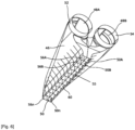
- the water release device 14 can have any type of shape.
- the water release device can be summed up in its simplest form as an extension of the tubes 12 and be integrated into the system 8. Indeed it could be envisaged to allow the ends 18 of the tubes 12 of the rear door 6 to protrude beyond beyond the end 20 thereof.
- the modular system 8 is equipped with a device 14 for releasing fluid and in the example described for releasing water.
- the purpose of the water release device 14 is to modify the direction of the flow. From a longitudinal direction, the device 14 makes it possible to project the water flow in a different direction.
- the device 14 makes it possible to release the water in an appropriate direction and for example perpendicular to the longitudinal direction, namely a vertical direction Z or close to a vertical direction if the aircraft in flight is not located not in a horizontal position.
- the device 14 also has another advantage which is to distribute the release into several flows whose use can be independently controlled for each of the flows, namely authorized or not. Thus, depending on the intensity of the fire, only part of the flow could be used, which makes it possible to save a quantity of water for another fire, another location of the fire or for other purposes.
- the water release device comprises a closed tank 46 having at least one opening 48 for the entry of water and at least one opening 50 for the release of water towards the outside of the aircraft.
- the opening 48 has a shape allowing the tank to fit onto the tube(s) 12 so as to form a tight connection in a known manner.
- the tank has two openings 48A, 48B extending in the form of sleeves 52, 54 allowing connection with the tubes 12.
- the sleeves 52 , 54 have a cylindrical shape of circular section.
- the tank 46 comprises several independent openings 50A, 50B ... 50n.
- the openings 50A, 50B ... 50n are butted to each other.
- the openings 50A, 50B ... 50n are contiguous so as to circumscribe the whole in the same larger opening 51 of geometric shape determined by the shape of the openings 50A, 50B, ... 50n.
- each opening 50A, 50B ... 50n is rectangular in shape.
- the contiguous openings 50A, 50B ... 50n are circumscribed in the same large rectangular opening 51 split into several openings 50A, 50B, ... 50n.
- the openings 50A, 50B, ... 50n are included in a plane parallel to the plane XY, namely a plane perpendicular to a transverse plane YZ to the tubes.
- the openings 50A, 50B, ... 50n are oriented so as to guide the flows flowing through them towards the ground, namely in a vertical direction Z.
- the aircraft In flight, the aircraft can fly in a nose-up position.
- the rear door 6 in the open position can be located in the extension of the floor 9 of the aircraft.
- the release device 14 arranged beyond the door 6 but in its longitudinal extension is not in a horizontal position in flight.
- the plane in which the openings 50A, 50B...50n are arranged is chosen according to the desired water release direction.
- the plane of the openings can be fixed (embodiment illustrated) or individually adjustable or not or with the choice of being able to adjust them individually or not.
- the tank has a shape making it possible to form water flow conduits 53A, 53B, ... 53n whose outlet orifice corresponds to each opening 50A, 50B ... 50n.
- the conduits are here of parallelepiped shape of rectangular section forming together a parallelepiped block of rectangular section whose outlet orifice corresponds to the rectangular opening 51.
- the section of each conduit could be equally square.
- the external contours of the ducts could be rounded for aerodynamic purposes.
- the axis of each conduit 53A, 53B, ... 53n corresponds to the axis of the corresponding opening 50A, 50B ... 50n.
- the openings 50A, 50B ... 50n are each capable of being closed by a valve 55 taking, in the illustrated embodiment, the shape of a flap respectively 56A, 56B, ... 56n.
- each conduit 53A, 53B, ... 53n is provided with a flap 56A, 56B, ... 56n.
- the opening and closing of each shutter 56A, 56B,... 56n can be controlled independently for each shutter by a control device 58 described below.
- the flaps 56 make it possible to adjust the flow rate of released fluid.
- the tank 46 has the shape of a funnel, namely whose dimensions in a plane parallel to the XY plane decrease going vertically downwards, the largest dimension being at the height of the tubes so as to guide the water towards the opening(s) 50.
- the lowest part of the tank in the shape illustrated is the dimensions of the opening 51.
- the flaps 56 are each in the form of an articulated flat panel 60 around an axis parallel to the Y direction; the hinge pin is for each central panel longitudinally. In the open position, the panels 60 are each in a plane parallel to the plane YZ and all parallel to each other.
- the panels are in a plane parallel to the XY plane, contiguous, abutting each other without superposing each other, each closing the corresponding opening 50A, 50B, ... 50n and closing the aforementioned rectangular opening 51. Any other form of realization is possible.
- the tank 46 has a dimension in a plane parallel to the plane YZ decreasing longitudinally away from the openings 48. Any other shape of tank is possible as long as it has inlet openings 48 and openings 50 outlet allowing the change of direction of the flow to release the water in the direction of the fire and thus reduce its dispersion.
- the release device 14 is retractable. Indeed, to allow the rear door 6 to close, it is necessary that the device 14 does not protrude from the end 20 of the rear door.
- the release device is linked to the tube or said tubes 12 via a hinge arranged at the top of each of the tubes 12 and sleeves 52, 54 allowing the device to pivot around an axis transverse parallel to the direction Y.
- a peripheral seal is provided between the tube(s) 12 and the sleeve(s) 52, 54 to ensure sealing when the sleeve(s) are in the release position in the extension of the tube(s) 12.
- at least part of the tube(s) are made in a telescopic manner to be able to reduce in length and allow the release device 14 to no longer protrude from the end 20.
- the release device 14 is not retractable. Indeed, it is possible for certain host aircraft to fly with the rear door 6 open.
- the system 8 is controlled using a control device 58 capable of being manipulated directly by a pilot and/or a co-pilot and/or a third man in the cockpit and/or any other operator whose function is to trigger the release of water and/or prepare the appropriate quantity. Control could also be envisaged from the ground, the control device then being connected to the aircraft by any type of known wireless communication means.
- the device 58 represented by a rectangle in the aircraft in the example illustrated on the Figure 7 , is connected to system 8 to ensure control. According to the embodiment described above, the device 58 is connected to the closing valves of the tubes 12 on the side of the tank and/or to the closing flaps 56.
- the device can be used by a third man 62 (only the seat on which he is intended to sit is shown) or from the cockpit 64 depending on the choice made by the pilot and/or the third man.
- a third man 62 only the seat on which he is intended to sit is shown
- the cockpit 64 depending on the choice made by the pilot and/or the third man.
- the following description presents a possible embodiment of the control device but any other form is possible.
- the control device 58 is in the form of a gun 66 having a trigger 68, a control panel 70 and a handle 72 for gripping.
- the control panel 70 presents means of configuring several criteria having an influence on the necessary quantity of water to be released. It is thus possible to control the quantity of water using the valves 13 and/or 55 presented previously and this according to different criteria.
- the gun 66 includes an internal processor in which an algorithm is programmed to determine the quantity of water and more precisely the necessary flow and the duration according to the criteria entered.
- the control panel 70 includes thumbwheel buttons 74 to incrementally adjust each criterion. Each button 74 allows you to adjust a criterion.
- the altitude (A) of release of the aircraft - there speed (PS) of the aircraft; - wind speed (WS); - the soil concerned (VH) and for example the height and/or type of vegetation and/or the type of soil.
- PS altitude
- WS wind speed
- VH soil concerned
- the quantity of water required is not necessarily the same.
- Other criteria may be added via such a control panel or in a different way.
- the release rate can vary depending on the ground over which the aircraft is flying. In this case, it is no longer with the help of a button that the ground concerned is entered but with a recorded map of the ground flown over.
- the flow rate can be significant if the height of vegetation is high and then decrease or even stop in the presence of a clearing. It is possible to program only certain criteria or all of them.
- the control panel 70 has a display screen 76 for displaying information. So for example, when the altitude button is manipulated, the selected altitude is displayed on the screen 76.
- Other types of display can be used such as for example simple light emitting diodes (LEDs) or lines of diodes electroluminescent.
- the trigger 68 When the aircraft arrives on the scene, all that remains for the person designated to activate the water release is to activate the trigger 68: the valves controlled by the trigger 68, namely the valves 13 for closing the tubes 12 on the side of the tank 10 and/or the required valves 55 (shutters 56) open and the calculated quantity of water will be released onto the fire to be extinguished for the determined duration.
Landscapes
- Engineering & Computer Science (AREA)
- Aviation & Aerospace Engineering (AREA)
- Life Sciences & Earth Sciences (AREA)
- Biodiversity & Conservation Biology (AREA)
- Ecology (AREA)
- Forests & Forestry (AREA)
- Health & Medical Sciences (AREA)
- Public Health (AREA)
- Business, Economics & Management (AREA)
- Emergency Management (AREA)
- Fire-Extinguishing By Fire Departments, And Fire-Extinguishing Equipment And Control Thereof (AREA)
- Buildings Adapted To Withstand Abnormal External Influences (AREA)
Applications Claiming Priority (1)
| Application Number | Priority Date | Filing Date | Title |
|---|---|---|---|
| FR2208686 | 2022-08-30 |
Publications (2)
| Publication Number | Publication Date |
|---|---|
| EP4331986A1 true EP4331986A1 (de) | 2024-03-06 |
| EP4331986B1 EP4331986B1 (de) | 2025-08-13 |
Family
ID=84887434
Family Applications (1)
| Application Number | Title | Priority Date | Filing Date |
|---|---|---|---|
| EP23192071.1A Active EP4331986B1 (de) | 2022-08-30 | 2023-08-18 | Steuervorrichtung auf basis mindestens eines parameterkriteriums eines flüssigkeitsausstosssystems für ein host-feuerkontrollflugzeug |
Country Status (3)
| Country | Link |
|---|---|
| US (1) | US20240066337A1 (de) |
| EP (1) | EP4331986B1 (de) |
| CA (1) | CA3209764A1 (de) |
Citations (4)
| Publication number | Priority date | Publication date | Assignee | Title |
|---|---|---|---|---|
| US5279481A (en) * | 1992-08-25 | 1994-01-18 | Air Tractor Inc. | Airborne liquid-spreading system |
| WO2004108528A2 (en) * | 2003-06-11 | 2004-12-16 | Evergreen International Aviation, Inc. | Aerial delivery system |
| US20060260826A1 (en) * | 2004-01-10 | 2006-11-23 | Hutter Michael D | Portable airborne firefighting and sensing system |
| US20210198934A1 (en) * | 2018-07-09 | 2021-07-01 | Victor D. Trotter | Aerial Firefighting Dump Gate System |
Family Cites Families (5)
| Publication number | Priority date | Publication date | Assignee | Title |
|---|---|---|---|---|
| US5320185A (en) * | 1992-06-15 | 1994-06-14 | Erickson Air-Crane Co. | Aircraft fluid drop system |
| US7124964B2 (en) * | 2002-09-13 | 2006-10-24 | Quy Duc Bui | Nozzle with flow rate and droplet size control capability |
| US7303168B1 (en) * | 2005-02-25 | 2007-12-04 | Lazes Richard J | Aircraft spraying conversion kit for use in extinguishing fires |
| WO2012058677A2 (en) * | 2010-10-29 | 2012-05-03 | Minden Air Corp. | Pressure assisted variable flow clean throat aerial retardant delivery system |
| US20120261144A1 (en) * | 2011-04-14 | 2012-10-18 | The Boeing Company | Fire Management System |
-
2023
- 2023-08-18 CA CA3209764A patent/CA3209764A1/fr active Pending
- 2023-08-18 EP EP23192071.1A patent/EP4331986B1/de active Active
- 2023-08-18 US US18/452,192 patent/US20240066337A1/en active Pending
Patent Citations (4)
| Publication number | Priority date | Publication date | Assignee | Title |
|---|---|---|---|---|
| US5279481A (en) * | 1992-08-25 | 1994-01-18 | Air Tractor Inc. | Airborne liquid-spreading system |
| WO2004108528A2 (en) * | 2003-06-11 | 2004-12-16 | Evergreen International Aviation, Inc. | Aerial delivery system |
| US20060260826A1 (en) * | 2004-01-10 | 2006-11-23 | Hutter Michael D | Portable airborne firefighting and sensing system |
| US20210198934A1 (en) * | 2018-07-09 | 2021-07-01 | Victor D. Trotter | Aerial Firefighting Dump Gate System |
Also Published As
| Publication number | Publication date |
|---|---|
| US20240066337A1 (en) | 2024-02-29 |
| EP4331986B1 (de) | 2025-08-13 |
| CA3209764A1 (fr) | 2024-02-29 |
Similar Documents
| Publication | Publication Date | Title |
|---|---|---|
| EP3929080A1 (de) | Brandbekämpfungsvorrichtung | |
| CA2790463C (fr) | Systeme d'acces a un habitacle | |
| FR2917376A1 (fr) | Meuble d'office d'aeronef et aeronef comportant un tel meuble | |
| FR2817828A1 (fr) | Appareil de largage de liquide pour un helicoptere | |
| WO2017207942A2 (fr) | Tourelle canon comportant au moins un magasin a munition et caisse a munitions destinee a equiper un tel magasin | |
| EP4331986B1 (de) | Steuervorrichtung auf basis mindestens eines parameterkriteriums eines flüssigkeitsausstosssystems für ein host-feuerkontrollflugzeug | |
| FR3065438A1 (fr) | Systeme de prise d'air multiposition pour un aeronef | |
| EP4331984B1 (de) | Vorrichtung zum auslösen von flüssigkeit in einer bestimmten richtung für ein flugzeug zur brandbekämpfung und flugzeug mit einer solchen vorrichtung | |
| EP4331985A1 (de) | Modulares flüssigkeitsaufbewahrungs- und -abwurfsystem und flugzeug mit einem solchen system | |
| FR3071227B1 (fr) | Drone de transport de conteneur | |
| CA3023784A1 (fr) | Engin roulant, notamment pour la depose au sol de materiaux en vrac | |
| EP1966005B1 (de) | Logistikbox | |
| EP3003791A1 (de) | In die armatur eines fahrzeugs eingebaute, mobile aufteilungsvorrichtung | |
| FR3027831A1 (fr) | Dispositif robotise pour acceder dans un compartiment d'un aeronef | |
| WO2023062290A1 (fr) | Dispositif de lutte contre les incendies | |
| EP3002541A1 (de) | Sitz für fahrzeug | |
| FR2610894A1 (fr) | Procede et appareillage pour projeter un produit liquide ou analogue, ou un objet solide, a partir d'un aeronef | |
| EP3579945B1 (de) | Gehäuse zur anordnung an einem fahrzeug und waffenanlage mit solch einem gehäuse | |
| FR3063697A1 (fr) | Cloison de protection pour un vehicule automobile utilitaire | |
| FR3094959A1 (fr) | Véhicule aérien sans pilote embarqué, adapté à la lutte contre les incendies, et en particulier contre les reprises de feu | |
| FR2749126A1 (fr) | Tremie ravitailleuse pour un tracteur equipe d'un semoir | |
| FR3006285A1 (fr) | Dispositif de cloisonnement integre a la console centrale d'un vehicule | |
| EP4442577A1 (de) | Reaktormast zur befestigung eines flugzeugmotors | |
| FR2828676A1 (fr) | Avion super-cargo de lutte contre les feux de foret | |
| FR2662905A1 (fr) | Appareil de pulverisation pour vehicule de traitement agricole. |
Legal Events
| Date | Code | Title | Description |
|---|---|---|---|
| PUAI | Public reference made under article 153(3) epc to a published international application that has entered the european phase |
Free format text: ORIGINAL CODE: 0009012 |
|
| STAA | Information on the status of an ep patent application or granted ep patent |
Free format text: STATUS: EXAMINATION IS IN PROGRESS |
|
| 17P | Request for examination filed |
Effective date: 20230818 |
|
| AK | Designated contracting states |
Kind code of ref document: A1 Designated state(s): AL AT BE BG CH CY CZ DE DK EE ES FI FR GB GR HR HU IE IS IT LI LT LU LV MC ME MK MT NL NO PL PT RO RS SE SI SK SM TR |
|
| RBV | Designated contracting states (corrected) |
Designated state(s): AL AT BE BG CH CY CZ DE DK EE ES FI FR GB GR HR HU IE IS IT LI LT LU LV MC ME MK MT NL NO PL PT RO RS SE SI SK SM TR |
|
| GRAP | Despatch of communication of intention to grant a patent |
Free format text: ORIGINAL CODE: EPIDOSNIGR1 |
|
| STAA | Information on the status of an ep patent application or granted ep patent |
Free format text: STATUS: GRANT OF PATENT IS INTENDED |
|
| RIC1 | Information provided on ipc code assigned before grant |
Ipc: A62C 3/02 20060101ALN20250310BHEP Ipc: B64D 1/16 20060101AFI20250310BHEP |
|
| INTG | Intention to grant announced |
Effective date: 20250403 |
|
| GRAS | Grant fee paid |
Free format text: ORIGINAL CODE: EPIDOSNIGR3 |
|
| GRAA | (expected) grant |
Free format text: ORIGINAL CODE: 0009210 |
|
| STAA | Information on the status of an ep patent application or granted ep patent |
Free format text: STATUS: THE PATENT HAS BEEN GRANTED |
|
| AK | Designated contracting states |
Kind code of ref document: B1 Designated state(s): AL AT BE BG CH CY CZ DE DK EE ES FI FR GB GR HR HU IE IS IT LI LT LU LV MC ME MK MT NL NO PL PT RO RS SE SI SK SM TR |
|
| REG | Reference to a national code |
Ref country code: GB Ref legal event code: FG4D Free format text: NOT ENGLISH |
|
| REG | Reference to a national code |
Ref country code: CH Ref legal event code: EP |
|
| REG | Reference to a national code |
Ref country code: DE Ref legal event code: R096 Ref document number: 602023005654 Country of ref document: DE |
|
| REG | Reference to a national code |
Ref country code: IE Ref legal event code: FG4D Free format text: LANGUAGE OF EP DOCUMENT: FRENCH |
|
| PGFP | Annual fee paid to national office [announced via postgrant information from national office to epo] |
Ref country code: DE Payment date: 20250820 Year of fee payment: 3 |
|
| PGFP | Annual fee paid to national office [announced via postgrant information from national office to epo] |
Ref country code: AT Payment date: 20251020 Year of fee payment: 3 |
|
| REG | Reference to a national code |
Ref country code: NL Ref legal event code: MP Effective date: 20250813 |
|
| PG25 | Lapsed in a contracting state [announced via postgrant information from national office to epo] |
Ref country code: IS Free format text: LAPSE BECAUSE OF FAILURE TO SUBMIT A TRANSLATION OF THE DESCRIPTION OR TO PAY THE FEE WITHIN THE PRESCRIBED TIME-LIMIT Effective date: 20251213 |
|
| PG25 | Lapsed in a contracting state [announced via postgrant information from national office to epo] |
Ref country code: NO Free format text: LAPSE BECAUSE OF FAILURE TO SUBMIT A TRANSLATION OF THE DESCRIPTION OR TO PAY THE FEE WITHIN THE PRESCRIBED TIME-LIMIT Effective date: 20251113 |
|
| REG | Reference to a national code |
Ref country code: LT Ref legal event code: MG9D |
|
| PG25 | Lapsed in a contracting state [announced via postgrant information from national office to epo] |
Ref country code: PT Free format text: LAPSE BECAUSE OF FAILURE TO SUBMIT A TRANSLATION OF THE DESCRIPTION OR TO PAY THE FEE WITHIN THE PRESCRIBED TIME-LIMIT Effective date: 20251215 |
|
| PG25 | Lapsed in a contracting state [announced via postgrant information from national office to epo] |
Ref country code: FI Free format text: LAPSE BECAUSE OF FAILURE TO SUBMIT A TRANSLATION OF THE DESCRIPTION OR TO PAY THE FEE WITHIN THE PRESCRIBED TIME-LIMIT Effective date: 20250813 |
|
| PG25 | Lapsed in a contracting state [announced via postgrant information from national office to epo] |
Ref country code: HR Free format text: LAPSE BECAUSE OF FAILURE TO SUBMIT A TRANSLATION OF THE DESCRIPTION OR TO PAY THE FEE WITHIN THE PRESCRIBED TIME-LIMIT Effective date: 20250813 Ref country code: NL Free format text: LAPSE BECAUSE OF FAILURE TO SUBMIT A TRANSLATION OF THE DESCRIPTION OR TO PAY THE FEE WITHIN THE PRESCRIBED TIME-LIMIT Effective date: 20250813 |
|
| PGFP | Annual fee paid to national office [announced via postgrant information from national office to epo] |
Ref country code: FR Payment date: 20251007 Year of fee payment: 3 |
|
| PG25 | Lapsed in a contracting state [announced via postgrant information from national office to epo] |
Ref country code: GR Free format text: LAPSE BECAUSE OF FAILURE TO SUBMIT A TRANSLATION OF THE DESCRIPTION OR TO PAY THE FEE WITHIN THE PRESCRIBED TIME-LIMIT Effective date: 20251114 |
|
| PG25 | Lapsed in a contracting state [announced via postgrant information from national office to epo] |
Ref country code: SE Free format text: LAPSE BECAUSE OF FAILURE TO SUBMIT A TRANSLATION OF THE DESCRIPTION OR TO PAY THE FEE WITHIN THE PRESCRIBED TIME-LIMIT Effective date: 20250813 |
|
| PG25 | Lapsed in a contracting state [announced via postgrant information from national office to epo] |
Ref country code: LV Free format text: LAPSE BECAUSE OF FAILURE TO SUBMIT A TRANSLATION OF THE DESCRIPTION OR TO PAY THE FEE WITHIN THE PRESCRIBED TIME-LIMIT Effective date: 20250813 |
|
| PG25 | Lapsed in a contracting state [announced via postgrant information from national office to epo] |
Ref country code: PL Free format text: LAPSE BECAUSE OF FAILURE TO SUBMIT A TRANSLATION OF THE DESCRIPTION OR TO PAY THE FEE WITHIN THE PRESCRIBED TIME-LIMIT Effective date: 20250813 Ref country code: BG Free format text: LAPSE BECAUSE OF FAILURE TO SUBMIT A TRANSLATION OF THE DESCRIPTION OR TO PAY THE FEE WITHIN THE PRESCRIBED TIME-LIMIT Effective date: 20250813 |
|
| PG25 | Lapsed in a contracting state [announced via postgrant information from national office to epo] |
Ref country code: RS Free format text: LAPSE BECAUSE OF FAILURE TO SUBMIT A TRANSLATION OF THE DESCRIPTION OR TO PAY THE FEE WITHIN THE PRESCRIBED TIME-LIMIT Effective date: 20251113 |
|
| PG25 | Lapsed in a contracting state [announced via postgrant information from national office to epo] |
Ref country code: ES Free format text: LAPSE BECAUSE OF FAILURE TO SUBMIT A TRANSLATION OF THE DESCRIPTION OR TO PAY THE FEE WITHIN THE PRESCRIBED TIME-LIMIT Effective date: 20250813 |
|
| REG | Reference to a national code |
Ref country code: AT Ref legal event code: MK05 Ref document number: 1824436 Country of ref document: AT Kind code of ref document: T Effective date: 20250813 |
|
| PG25 | Lapsed in a contracting state [announced via postgrant information from national office to epo] |
Ref country code: RO Free format text: LAPSE BECAUSE OF FAILURE TO SUBMIT A TRANSLATION OF THE DESCRIPTION OR TO PAY THE FEE WITHIN THE PRESCRIBED TIME-LIMIT Effective date: 20250813 |