EP4331927B1 - Steuergerät zum schätzen der achsgewichte eines schienenfahrzeugs, computerimplementiertes verfahren dazu, computerprogramm und nichtflüchtiger datenträger - Google Patents
Steuergerät zum schätzen der achsgewichte eines schienenfahrzeugs, computerimplementiertes verfahren dazu, computerprogramm und nichtflüchtiger datenträger Download PDFInfo
- Publication number
- EP4331927B1 EP4331927B1 EP22193702.2A EP22193702A EP4331927B1 EP 4331927 B1 EP4331927 B1 EP 4331927B1 EP 22193702 A EP22193702 A EP 22193702A EP 4331927 B1 EP4331927 B1 EP 4331927B1
- Authority
- EP
- European Patent Office
- Prior art keywords
- wheel
- wheel axles
- rail vehicle
- controller
- wheel axle
- Prior art date
- Legal status (The legal status is an assumption and is not a legal conclusion. Google has not performed a legal analysis and makes no representation as to the accuracy of the status listed.)
- Active
Links
Images
Classifications
-
- B—PERFORMING OPERATIONS; TRANSPORTING
- B60—VEHICLES IN GENERAL
- B60T—VEHICLE BRAKE CONTROL SYSTEMS OR PARTS THEREOF; BRAKE CONTROL SYSTEMS OR PARTS THEREOF, IN GENERAL; ARRANGEMENT OF BRAKING ELEMENTS ON VEHICLES IN GENERAL; PORTABLE DEVICES FOR PREVENTING UNWANTED MOVEMENT OF VEHICLES; VEHICLE MODIFICATIONS TO FACILITATE COOLING OF BRAKES
- B60T8/00—Arrangements for adjusting wheel-braking force to meet varying vehicular or ground-surface conditions, e.g. limiting or varying distribution of braking force
- B60T8/17—Using electrical or electronic regulation means to control braking
- B60T8/1701—Braking or traction control means specially adapted for particular types of vehicles
- B60T8/1705—Braking or traction control means specially adapted for particular types of vehicles for rail vehicles
-
- B—PERFORMING OPERATIONS; TRANSPORTING
- B60—VEHICLES IN GENERAL
- B60T—VEHICLE BRAKE CONTROL SYSTEMS OR PARTS THEREOF; BRAKE CONTROL SYSTEMS OR PARTS THEREOF, IN GENERAL; ARRANGEMENT OF BRAKING ELEMENTS ON VEHICLES IN GENERAL; PORTABLE DEVICES FOR PREVENTING UNWANTED MOVEMENT OF VEHICLES; VEHICLE MODIFICATIONS TO FACILITATE COOLING OF BRAKES
- B60T17/00—Component parts, details, or accessories of power brake systems not covered by groups B60T8/00, B60T13/00 or B60T15/00, or presenting other characteristic features
- B60T17/18—Safety devices; Monitoring
- B60T17/22—Devices for monitoring or checking brake systems; Signal devices
- B60T17/228—Devices for monitoring or checking brake systems; Signal devices for railway vehicles
-
- B—PERFORMING OPERATIONS; TRANSPORTING
- B60—VEHICLES IN GENERAL
- B60T—VEHICLE BRAKE CONTROL SYSTEMS OR PARTS THEREOF; BRAKE CONTROL SYSTEMS OR PARTS THEREOF, IN GENERAL; ARRANGEMENT OF BRAKING ELEMENTS ON VEHICLES IN GENERAL; PORTABLE DEVICES FOR PREVENTING UNWANTED MOVEMENT OF VEHICLES; VEHICLE MODIFICATIONS TO FACILITATE COOLING OF BRAKES
- B60T8/00—Arrangements for adjusting wheel-braking force to meet varying vehicular or ground-surface conditions, e.g. limiting or varying distribution of braking force
- B60T8/17—Using electrical or electronic regulation means to control braking
- B60T8/172—Determining control parameters used in the regulation, e.g. by calculations involving measured or detected parameters
-
- B—PERFORMING OPERATIONS; TRANSPORTING
- B60—VEHICLES IN GENERAL
- B60T—VEHICLE BRAKE CONTROL SYSTEMS OR PARTS THEREOF; BRAKE CONTROL SYSTEMS OR PARTS THEREOF, IN GENERAL; ARRANGEMENT OF BRAKING ELEMENTS ON VEHICLES IN GENERAL; PORTABLE DEVICES FOR PREVENTING UNWANTED MOVEMENT OF VEHICLES; VEHICLE MODIFICATIONS TO FACILITATE COOLING OF BRAKES
- B60T8/00—Arrangements for adjusting wheel-braking force to meet varying vehicular or ground-surface conditions, e.g. limiting or varying distribution of braking force
- B60T8/18—Arrangements for adjusting wheel-braking force to meet varying vehicular or ground-surface conditions, e.g. limiting or varying distribution of braking force responsive to vehicle weight or load, e.g. load distribution
- B60T8/1893—Arrangements for adjusting wheel-braking force to meet varying vehicular or ground-surface conditions, e.g. limiting or varying distribution of braking force responsive to vehicle weight or load, e.g. load distribution especially adapted for railway vehicles
-
- B—PERFORMING OPERATIONS; TRANSPORTING
- B60—VEHICLES IN GENERAL
- B60T—VEHICLE BRAKE CONTROL SYSTEMS OR PARTS THEREOF; BRAKE CONTROL SYSTEMS OR PARTS THEREOF, IN GENERAL; ARRANGEMENT OF BRAKING ELEMENTS ON VEHICLES IN GENERAL; PORTABLE DEVICES FOR PREVENTING UNWANTED MOVEMENT OF VEHICLES; VEHICLE MODIFICATIONS TO FACILITATE COOLING OF BRAKES
- B60T8/00—Arrangements for adjusting wheel-braking force to meet varying vehicular or ground-surface conditions, e.g. limiting or varying distribution of braking force
- B60T8/32—Arrangements for adjusting wheel-braking force to meet varying vehicular or ground-surface conditions, e.g. limiting or varying distribution of braking force responsive to a speed condition, e.g. acceleration or deceleration
- B60T8/321—Arrangements for adjusting wheel-braking force to meet varying vehicular or ground-surface conditions, e.g. limiting or varying distribution of braking force responsive to a speed condition, e.g. acceleration or deceleration deceleration
- B60T8/3235—Systems specially adapted for rail vehicles
-
- B—PERFORMING OPERATIONS; TRANSPORTING
- B60—VEHICLES IN GENERAL
- B60T—VEHICLE BRAKE CONTROL SYSTEMS OR PARTS THEREOF; BRAKE CONTROL SYSTEMS OR PARTS THEREOF, IN GENERAL; ARRANGEMENT OF BRAKING ELEMENTS ON VEHICLES IN GENERAL; PORTABLE DEVICES FOR PREVENTING UNWANTED MOVEMENT OF VEHICLES; VEHICLE MODIFICATIONS TO FACILITATE COOLING OF BRAKES
- B60T2240/00—Monitoring, detecting wheel/tyre behaviour; counteracting thereof
- B60T2240/06—Wheel load; Wheel lift
Definitions
- the present invention relates generally to rail vehicle traction systems. Especially, the invention relates to a controller according to the preamble of claim 1 for estimating the axle weights of a rail vehicle to enable enhanced traction control in operation of the rail vehicle. The invention also relates to a corresponding computer-implemented method, a computer program and a non-volatile data carrier storing such a computer program.
- US 9,358,846 describes a load estimation system and method for estimating vehicle load.
- the system includes a tire rotation counter for generating a rotation count from rotation of a tire; apparatus for measuring distance travelled by the vehicle; an effective radius calculator for calculating effective radius of the tire from the distance travelled and the rotation count; and a load estimation calculator for calculating the load carried by the vehicle tire from the effective radius of the tire.
- a center of gravity height estimation may be made from an estimated total load carried by the tires supporting the vehicle pursuant to an estimation of effective radius for each tire and a calculated load carried by each tire from respective effective radii.
- US 9,500,514 shows a method and a system for estimating a weight for a vehicle on the basis of at least two forces which act upon the vehicle.
- the forces are a motive force and at least one further force, and topographical information for a relevant section of road.
- the estimation is performed when the at least two forces are dominated by the motive force.
- US 9,211,879 discloses devices and methods, which relate to the arrangement of a sensor on the shaft of a rail vehicle to determine its mass. For example, an output signal of an acceleration sensor is evaluated, which is disposed on a shaft of the rail vehicle.
- the mass of a freight wagon can be determined in that it vibrates in a manner typical to the mass (frequency, amplitude) after impact (switching impact, running over a switch).
- the impact can be determined in direction and intensity by the acceleration sensor on the shaft (axle), the vibration can be determined by the same acceleration sensor or by a further sensor on the chassis. From this measurement data, the mass of the wagon and the mass of the load with known empty weight and thereby the loading state can be determined.
- the object of the present invention is to solve the above problems and offer a solution that enables determining the specific axle weights of a rail vehicle in an accurate and reliable manner.
- the object is achieved by a controller for estimating axle weights of a rail vehicle, which, in turn, contains a number of wheel axles and a set of drive units.
- Each drive unit is configured to apply a respective traction force to each wheel axle in a driving subset of the wheel axles so as to cause acceleration of the rail vehicle.
- the controller is configured to obtain a power signal and a speed signal.
- the power signal indicates an amount of power produced by the set of drive units to accelerate the rail vehicle from a first speed to a second speed, for example from zero to 5 km/h.
- the speed signal indicates respective values of the first and second speeds.
- the controller is configured to estimate an overall weight of the rail vehicle, and by executing the following steps, the controller is further configured to estimate how the overall weight is distributed over the vehicle's wheel axles: (a) obtaining wheel speed signals indicating respective rotational speeds of the wheel axles in the driving subset of the wheel axles; (b) producing an acceleration control signal to a specific drive unit in the set of drive units such that this drive unit applies a gradually increasing traction force to a specific wheel axle of the wheel axles in the driving subset of the wheel axles; (c) determining, repeatedly during production of the acceleration control signal, an absolute difference between the rotational speed of the specific wheel axle and an average rotational speed of the wheel axles In the driving subset of the wheel axles except the specific wheel axle; and in response to the absolute difference exceeding a threshold value (d) determining a parameter that reflects a friction coefficient between a pair of wheels on the specific wheel axle and a pair of rails upon which the rail vehicle travels; repeating steps (a) to (c)
- the above controller is advantageous because it provides accurate values of the overall weight of the rail vehicle as well as its axle weights. As a bonus effect, this also enables the rail vehicle to brake without risking slippage.
- the proposed controller is beneficial, since it allows for dynamic adaptation of the acceleration and braking functionality during travel in response to any redistribution of the load, e.g. due to passengers moving around in a train. More important, it is possible to apply dynamic moving block control of a rail vehicle, wherein the control is appropriately adjusted in response to cargo being loaded/unloaded and/or passengers embarking/disembarking.
- the controller is further configured to: (e) obtain wheel speed signals indicating respective rotational speeds of each wheel axle of the rail vehicle, (f) produce a brake control signal to a brake unit configured to apply a brake force to the non-driven wheel axle such that this brake unit applies a gradually increasing brake force to the non-driven wheel axle, (g) determine, repeatedly during production of the brake control signal, an absolute difference between the rotational speed of the non-driven wheel axle and an average rotational speed of the wheel axles except the non-driven wheel axle; and in response to the absolute difference exceeding a threshold value (h) determine a parameter reflecting a friction coefficient between a pair of wheels on the specific wheel axle and the pair of rails upon which the rail vehicle travels.
- the controller is configured to repeat steps (e) to (g) for each of the non-driven wheel axles, and based thereon estimate a respective fraction of the overall weight carried by each of the non-driven wheel axles. Thereby, individual axle weights can be determined for the entire set of wheel axles of a rail vehicle.
- the controller contains a first interface configured to receive a first vector signal expressing an inclination angle of the rail vehicle relative to a horizontal plane.
- the controller is configured to adjust the power signal indicating the amount of power produced by the onboard motor and/or the speed signal indicating the second speed based on the inclination angle when estimating the overall weight of the rail vehicle.
- Such adjustment is necessary if the overall weight of the rail vehicle is estimated when the rail vehicle travels on non-horizontal ground because in an uphill slope a part of the motor power is converted into potential energy, and conversely, in a downhill slope a part of the kinetic energy originates from potential energy.
- the controller also has a second interface configured to receive a second vector signal expressing a respective rotational movement of the wheels on each wheel axle in the driving subset of the wheel axles, which rotational movement is performed in a plane orthogonal to a respective rotation axis of the wheel axle.
- the controller is further configured to obtain the wheel speed signals indicating the respective rotational speeds based on the first and second vector signals.
- the controller is further configured to obtain the wheel speed signals indicating the respective rotational speeds based on the first and second vector signals.
- the controller is configured to provide the respective fractions of the overall weight to a traction controller to enable the traction controller to produce a respective acceleration control signal to each drive unit in the set of drive units.
- respective acceleration control signals may be based on the respective fractions of the overall weight, and the rail vehicle can be accelerated in an optimized manner, for example enabling efficient control of the rail vehicle according to the dynamic moving blocks principle.
- the controller is configured to transmit the acceleration control signal via a data bus in the rail vehicle. This renders the implementation cost-efficient and flexible.
- the method further involves: (a) obtaining wheel speed signals indicating respective rotational speeds of the wheel axles in the driving subset of the wheel axles; (b) producing an acceleration control signal to a specific drive unit in the set of drive units such that this drive unit applies a gradually increasing traction force to a specific wheel axle of the wheel axles in the driving subset of the wheel axles; (c) determining, repeatedly during production of the acceleration control signal, an absolute difference between the rotational speed of the specific wheel axle and an average rotational speed of the wheel axles in the driving subset of the wheel axles except the specific wheel axle; and in response to the absolute difference exceeding a threshold value (d) determining a parameter reflecting a friction coefficient between a pair of wheels on the specific wheel axle and a pair of rails upon which the rail vehicle travels.
- Steps (a) to (c) are repeated for each of the wheel axles in the driving subset of the wheel axles, and based thereon a respective fraction of the overall weight carried by each of wheel axles in the driving subset of the wheel axles is estimated.
- the object is achieved by a computer program loadable into a non-volatile data carrier communicatively connected to a processing unit.
- the computer program includes software for executing the above method when the program is run on the processing unit.
- the object is achieved by a non-volatile data carrier containing the above computer program.
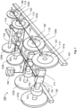
- FIG. 1 we see a schematic illustration of a rail vehicle 100 equipped with a controller 140 according to one embodiment of the invention.
- the controller 140 is arranged to estimate the different axle weights of the rail vehicle 100, which has a number of wheel axles.
- Figure 1 exemplifies four such wheel axles in the form of 131, 132, 133 and 134 respectively.
- a set of drive units 101, 102 and 103 is configured to apply a respective traction force to each wheel axle in a driving subset of the wheel axles 131, 132 and 133, such that the rail vehicle 100 accelerates.
- a set of brake units 181, 182, 183 and 184 is configured to apply a respective brake force to each of the wheel axles 131, 132, 133 and 134 respectively, such that the rail vehicle 100 decelerates.
- Each of the brake units 181, 182, 183 and 184 is associated with a respective rotatable member 111, 112, 113 and 114, such as a brake disc or a brake drum being mechanically linked to the respective wheel axle 131, 132, 133 and 134.
- At least one respective pressing member of each brake unit is configured to apply a brake force to the rotatable member so as to cause retardation of the wheel axle and the wheels thereon.
- a typical rail vehicle contains a substantially larger number of wheel axles than what is shown in Figure 1 .
- each bogie has two wheel axles carrying altogether four wheels, and each car body of the rail vehicle 100 includes a respective bogie in the front and rear ends.
- the controller 140 is configured to obtain a power signal P m indicating an amount of power being produced by the set of drive units 101, 102 and 103 when accelerating the rail vehicle 100 from a first speed v 1 to a second speed v 2 , for example from a standstill to 10 km/h.
- the power signal P m may equally well be received during acceleration of the rail vehicle 100 between any other two speed levels.
- the controller 140 is configured to obtain a speed signal indicating respective values of the first and second speeds v 1 and v 2 .
- the controller 140 is configured to estimate an overall weight m tot of the rail vehicle 100.
- controller 140 is further configured to:
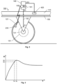
- Figure 3 shows a graph illustrating an example of how the kinetic friction coefficient ⁇ k may be expressed as a function of the wheel slippage s, which here is understood to designate a spinning motion of the wheel relative to the rail.
- the wheel slippage s may equally well express a sliding motion of the wheel relative to the rail.
- the wheel slippage s is applicable to an acceleration scenario as well as a retardation ditto.
- a parameter ⁇ m is determined that reflects the friction coefficient between the rail vehicle's 100 wheels and the rails 191 and 192 upon which the rail vehicle 100 travels.
- the peak value ⁇ e should be derived.
- the peak value ⁇ e may be derived as follows. When the absolute difference
- the peak value ⁇ e of the kinetic friction coefficient ⁇ k may be estimated relatively accurately; and the proximity of wheel slippage s m to the optimal wheel slippage s e is ensured by said threshold value for the absolute difference
- controller 140 is configured to repeat the above steps (a) to (c) for each wheel axle 131, 132 and 133 in the driving subset, and based thereon estimate a respective fraction m 1 , m 2 and m 3 of the overall weight m tot carried by each of these wheel axles.
- the above-mentioned specific wheel axle 131 does not need to be any particular wheel axle, e.g. a frontmost or a rearmost wheel axle of the rail vehicle 100.
- the above procedure may start with an arbitrary selected wheel axle in the driving subset.
- each wheel axle in the driving subset alternately either represents the specific wheel axle or is included in the complement set, i.e. all the wheel axles except the specific wheel axle.
- Repeated execution of procedure is nevertheless beneficial to enable adjustment of the braking functionality in response to any changes in the overall weight m tot and/or a redistribution of the overall weight m tot over the wheel axles.
- one or more of the rail vehicle's 100 wheel axles may be non-driven, i.e. not be comprised in the driving subset of the wheel axles 131, 132 and 133.
- the controller 140 is further configured execute the below procedure.
- the controller 140 may be configured to generate a control message ctrl A to make the acceleration controllers 161, 162 and 162 produce acceleration control signals A1, A2 and A3 to the drive units 101, 102 and 103 respectively, such that an average drive force applied to the wheel axles 132, and 133 except the specific wheel axles 131 is gradually decreased when the drive force applied to the specific wheel axle 131 is gradually increased.
- the driving on the other wheel axles 132 and 133 compensate for the somewhat excessive drive force applied to the specific wheel axle 131.
- this compensation is temporally matched.
- the controller 140 is configured to generate the control message ctrl A to cause the acceleration controllers 161, 162 and 162 to produce acceleration control signals A1, A2 and A3 to the drive units 101, 102 and 103 such that, at each point in time, the gradual decrease of the average drive force applied to the wheel axles 132 and 133 except the specific wheel axles 131 corresponds to the gradual increase of the drive force applied to the specific wheel axle 131. Namely, thereby the deviating drive force applied to specific wheel axle 131 is masked by the opposite deviation represented by the drive force applied to the wheel axles 132 and 133 in the driving subset.
- the drive unit 101 is configured to receive the acceleration control signal A1 from the acceleration controller 161, which, in turn, operates in response to the control message ctrl A from the controller 140.
- the acceleration control signal A1 may for example be transmitted via a data bus 150.
- the drive unit 101 is configured to drive the wheel axle 131.
- the drive unit 101 may contain at least one electric motor whose generated traction force depends on a magnitude of an electric current fed to it.
- the data bus 150 may, of course, be configured to transmit the all the acceleration and brake control signals A1, A2 and A3 and B1, B2, B3 and B4 respectively to each of the drive units 101, 102 and 103 and each of the brake units 181, 182, 183 and 184.
- the controller 140 contains at least one interface 511 and 512 configured to receive first and second vector signals VS1 and VS2 respectively.
- the first vector signal VS1 expresses an acceleration a X , a Y , a Z , a R , a P , and/or aw of the rail vehicle 100 in at least one dimension, for instance linearly in one or more spatial directions and/or rotations around one or more of these directions.
- the second vector signal VS2 expresses a respective rotational movement of the wheels 121a, 121b; 122a, 122b; 123a, 123b and 124a, 124b on each of the wheel axles. Consequently, since each wheel is configured to rotate around a respective one of the wheel axles, the rotational movement is performed in a plane being orthogonal to a respective rotation axis of the wheel axle.
- the controller 140 is configured to obtain the wheel speed signals indicating the respective rotational speeds ⁇ 1 , ⁇ 2 , ⁇ 3 and ⁇ 4 based on the first and second vector signals VS1 and VS2 by applying physical mechanics algorithms known in the art.
- determining the average rotational speed ⁇ a is trivial once each of the individual rotational speeds ⁇ 1 , ⁇ 2 , ⁇ 3 and ⁇ 4 is known.
- the first vector signal VS1 further expresses an inclination angle a of the rail vehicle 100 relative to a horizontal plane H.
- the controller 140 is configured to adjust the power signal P m indicating the amount of power produced by the onboard motor and/or the speed signal indicating the second speed v 2 based on the inclination angle ⁇ when estimating the overall weight m tot of the rail vehicle 100.
- the estimate of the overall weight m tot may be adequately adjusted if the rail vehicle 100 travels on non-horizontal ground when obtaining the power signal P m and the speed signal, such that in an uphill slope the part of the motor power that is converted into potential energy is discarded; and conversely, in a downhill slope the part of the kinetic energy originating from potential energy is discarded.
- Figure 2 illustrates a second accelerometer 235 that is eccentrically arranged relative to a rotation axis of at least one wheel, say 121.
- the second accelerometer 235 is configured to produce the second vector signal VS2 expressing movements of the second accelerometer 235 in a plane orthogonal to the rotation axis of the at least one wheel 121, and transmit a signal containing the second vector signal VS2 to the controller 140.
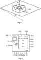
- FIG. 5 shows a block diagram of the controller 140 according to one embodiment of the invention.
- the controller 140 includes processing circuitry in the form of at least one processor 530 and a memory unit 520, i.e. non-volatile data carrier, storing a computer program 525, which, in turn, contains software for making the at least one processor 530 execute the actions mentioned in this description when the computer program 525 is run on the at least one processor 530.
- the controller 140 contains input interfaces configured to receive the first and second vector signals VS1 and VS2 respectively, the power signal P m and the speed signal expressing the speeds v 1 and v 2 respectively. Further, the controller 140 contains outputs configured to provide the acceleration control signals A1, A2 and A3, the brake control signals B1, B2, B3 and B4, and information about the individual axle weights, such as the respective fractions m 1 , m 2 , m 3 and m 4 of the overall weight m tot . As mentioned above, one or more of the input and/or output signals may be communicated via the data bus 150.
- the controller 140 is configured to provide the respective fractions m 1 , m 2 and m 3 of the overall weight m tot to each of the acceleration controllers 161, 162, and 163 to enable the acceleration controllers to cause its associated drive unit 101, 102 and 103 respectively to produce a respective appropriate traction force in response to the acceleration control signals A1, A2 and A3.
- the appropriate traction force is based on the respective fraction m 1 , m 2 or m 3 of the overall weight m tot applicable to the wheel axle in question 131, 132 or 133 respectively.
- the controller 140 is co-located with the acceleration controller.
- the controller 140 may be integrated into the acceleration controller 161, or vice versa.
- the functionality of the controller 140 may be distributed over two or more of the acceleration controllers 161, 162 and/or 163.
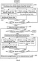
- a first step 605 signals are obtained that express first and second speeds v 1 and v 2 and an amount of power produced by the drive units of the rail vehicle 100 to accelerate it from the first speed v 1 to the second speed v 2 .
- a speed signal is obtained, which indicates a rotational speed ⁇ 1 of a specific one the rail vehicle's 100 wheel axles, say 131.
- step 615 preferably essentially parallel to step 610, an average value is obtained, which represents an average rotational speed ⁇ a of the rotational speeds ⁇ 2 and ⁇ 3 of the wheel axles 132 and 133 respectively in the driving subset of the wheel axles except the specific wheel axle 131
- an acceleration control signal is produced that is configured to cause a drive unit to apply an increased traction force to the specific wheel axle 131.
- a step 625 checks if an absolute difference
- a parameter ⁇ m is determined that reflects a friction coefficient ⁇ e between the wheels 121a and 121b on the specific wheel axle 131 and the rails 191 and 192 upon which the rail vehicle 100 travels.
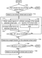
- a step 635 checks if all the wheel axles 131, 132, and 133 in the driving subset of the rail vehicle 100 have been tested. If so, the procedure ends. If not, the procedure continues to a step 640 in which a not yet tested driving wheel axle is selected.
- a speed signal is obtained, which indicates a rotational speed of the selected wheel axle.
- an average value is obtained, which represents an average of the rotational speeds of the rail vehicle's 100 wheel axles except the selected wheel axle.
- an acceleration control signal is produced that is configured to cause a drive unit to apply an increased traction force to the selected wheel axle.
- a step 660 checks if an absolute difference between the rotational speed of the selected wheel axle and the average rotational speed of the wheel axles except the selected wheel axle exceeds a threshold value. If so, a step 665 follows. Otherwise, the procedure loops back to steps 645 and 650.
- step 665 a respective fraction of the overall weight m tot carried by the selected wheel axle is estimated. Thereafter, the procedure loops back to step 635. It should be noted that the fraction of the overall weight m tot carried by the first wheel axle may be determined as a remaining faction of the overall weight m tot when the respective fractions on all the other wheel axles have been determined.
- a first step 705 it is checked if the rail vehicle has at least one non-driving wheel axle. If not, the procedure ends; and otherwise, a step 710 follows.
- step 710 one of the non-driven wheel axles is selected for testing. Thereafter, in a step 715, a wheel speed signals is obtained, which indicates a rotational speed ⁇ 4 of the selected wheel axle.
- an average speed signal is obtained, which represents an average rotational speed ⁇ a of the rotational speeds ⁇ 1 , ⁇ 2 and ⁇ 3 of each wheel axle of the rail vehicle except the selected non-driven wheel axle.
- a brake control signal is produced, which is configured to cause a brake unit to apply brake force to the selected non-driven wheel axle such that this brake unit applies a gradually increasing brake force to the non-driven wheel axle.
- a step 730 subsequent to steps 720 and 725 determines during production of the brake control signal, an absolute difference between the rotational speed of the selected non-driven wheel axle and the average rotational speed of the rail vehicle's wheel axles except the selected non-driven wheel axle. If the absolute difference exceeds a threshold value, the procedure continues to a step 735, and otherwise the procedure loops back to steps 715 and 720.
- a parameter is determined that reflects a friction coefficient between a pair of wheels on the selected wheel axle and the pair of rails upon which the rail vehicle travels. Based on the parameter, in turn, a fraction of the rail vehicle's overall weight carried by the selected non-driven wheel axles is determined.
- a step 740 checks if all non-driven wheel axles have been tested; and if so, the procedure ends. Otherwise, a step 745 follows in which a not yet tested wheel axles is selected for testing, and the procedure loops back to steps 715 and 720.
- All of the process steps, as well as any sub-sequence of steps, described with reference to Figures 6 and 7 may be controlled by means of a programmed processor.
- the embodiments of the invention described above with reference to the drawings comprise processor and processes performed in at least one processor, the invention thus also extends to computer programs, particularly computer programs on or in a carrier, adapted for putting the invention into practice.
- the program may be in the form of source code, object code, a code intermediate source and object code such as in partially compiled form, or in any other form suitable for use in the implementation of the process according to the invention.
- the program may either be a part of an operating system, or be a separate application.
- the carrier may be any entity or device capable of carrying the program.
- the carrier may comprise a storage medium, such as a Flash memory, a ROM (Read Only Memory), for example a DVD (Digital Video/Versatile Disk), a CD (Compact Disc) or a semiconductor ROM, an EPROM (Erasable Programmable Read-Only Memory), an EEPROM (Electrically Erasable Programmable Read-Only Memory), or a magnetic recording medium, for example a floppy disc or hard disc.
- the carrier may be a transmissible carrier such as an electrical or optical signal which may be conveyed via electrical or optical cable or by radio or by other means.
- the carrier When the program is embodied in a signal, which may be conveyed, directly by a cable or other device or means, the carrier may be constituted by such cable or device or means.
- the carrier may be an integrated circuit in which the program is embedded, the integrated circuit being adapted for performing, or for use in the performance of, the relevant processes.
Landscapes
- Engineering & Computer Science (AREA)
- Transportation (AREA)
- Mechanical Engineering (AREA)
- Electric Propulsion And Braking For Vehicles (AREA)
Claims (15)
- Steuerung (140) zum Schätzen der Achsgewichte eines Schienenfahrzeugs (100), das eine Anzahl von Radachsen (131, 132, 133, 134) und einen Satz von Antriebseinheiten (101, 102, 103), die konfiguriert sind, um eine jeweilige Traktionskraft auf jede Radachse in einem Antriebsteilsatz der Radachsen (131, 132, 133) anzuwenden, um die Beschleunigung des Schienenfahrzeugs (100) zu bewirken, wobei die Steuerung (140) konfiguriert ist, um zu gewinnen:ein Leistungssignal (Pm), das einen Betrag der Leistung anzeigt, die durch den Satz von Antriebseinheiten (101, 102, 103) erzeugt wird, um das Schienenfahrzeug (100) von einer ersten Geschwindigkeit (v1) auf eine zweite Geschwindigkeit (v2) zu beschleunigen,ein Geschwindigkeitssignal, das jeweilige Werte der ersten und zweiten Geschwindigkeiten (v1, v2) anzeigt, undbasierend darauf ein Gesamtgewicht (mtot) des Schienenfahrzeugs (100) zu schätzen, dadurch gekennzeichnet, dass die Steuerung (140) ferner konfiguriert ist, um zu schätzen, wie das Gesamtgewicht (mtot) über eine Anzahl von Radachsen (131, 132, 133, 134) verteilt ist, durch:(a) Gewinnen von Drehzahlsignalen, die jeweilige Drehzahlen (ω1, ω2, ω3) der Radachsen in dem Antriebsteilsatz der Radachsen (131, 132, 133) darstellen,(b) Erzeugen eines Beschleunigungssteuersignals (A1) an eine spezifische Antriebseinheit (101) in dem Satz von Antriebseinheiten, so dass diese Antriebseinheit eine allmählich zunehmende Traktionskraft auf eine spezifische Radachse (131) der Radachsen in dem Antriebsteilsatz der Radachsen (131, 132, 133) anwendet,(c) während der Erzeugung des Beschleunigungssteuersignals (A1) wiederholtes Bestimmen eines Differenzbetrags (| ω1 - ωa |) zwischen der Drehzahl der spezifischen Radachse (131) und einer mittleren Drehzahl (ωa) der Radachsen (132, 133) in dem Antriebsteilsatz der Radachsen, abgesehen von der spezifischen Radachse;
und ansprechend darauf, dass der Differenzbetrag (| ω1 - ωa |) einen Schwellwert überschreitet,(d) Bestimmen eines Parameters (µm), der einen Reibungskoeffizienten (µe) zwischen einem Paar von Rädern (121a, 121b) auf der spezifischen Radachse (131) und einem Paar von Schienen (191, 192), auf dem das Schienenfahrzeug (100) fährt, widerspiegelt,Wiederholen der Schritte (a) bis (c) für jede der Radachsen in dem Antriebsteilsatz der Radachsen und basierend darauf Schätzen eines jeweiligen Bruchteils (m1, m2, m3) des Gesamtgewichts (mtot), das von jeder der Radachsen in dem Antriebsteilsatz der Radachsen (131, 132, 133) getragen wird. - Steuerung (140) nach Anspruch 1, wobei die Steuerung (140) ferner für jede nicht angetriebene Radachse (134) der Anzahl von Radachsen, wobei die nichtangetriebene Radachse (134) nicht in dem Antriebsteilsatz der Radachsen (131, 132, 133) enthalten ist, konfiguriert ist, um:(e) Radgeschwindigkeitssignale, die jeweilige Drehzahlen (ω1, ω2, ω3, ω4) jeder Radachse der Anzahl von Radachsen (131, 132, 133, 134) anzeigen, zu gewinnen,(f) ein Bremssteuersignal (B4) an eine Bremseinheit (184) zu erzeugen, die konfiguriert ist, um eine Bremskraft auf die nicht angetriebene Radachse (134) anzuwenden, so dass diese Bremseinheit eine allmählich zunehmende Bremskraft auf die nicht angetriebene Radachse (134) anwendet,(g) wiederholt während der Erzeugung des Beschleunigungssteuersignals (B4) einen Differenzbetrag (| ω4 - ωa |) zwischen der Drehzahl der nicht angetriebenen Radachse (134) und einer mittleren Drehzahl (ωa) der Anzahl von Radachsen (132, 133), abgesehen von der nicht angetriebenen Radachse (134) zu bestimmen; und ansprechend darauf, dass der Differenzbetrag einen Schwellwert überschreitet,(h) einen Parameter (µm), der einen Reibungskoeffizienten (µe) zwischen einem Paar von Rädern (124a, 124b) auf der spezifischen Radachse (134) und einem Paar von Schienen (191, 192), auf dem das Schienenfahrzeug (100) fährt, widerspiegelt, zu bestimmen,die Schritte (e) bis (g) für jede der nicht angetriebenen Radachsen zu wiederholen und basierend darauf einen jeweiligen Bruchteil (m4) des Gesamtgewichts (mtot), der von jeder der nicht angetriebenen Radachsen getragen wird, zu schätzen.
- Steuerung (140) nach einem der Ansprüche 1 oder 2, die eine erste Schnittstelle (511) aufweist, die konfiguriert ist, um ein erstes Vektorsignal (VS1), das einen Neigungswinkel (α) des Schienenfahrzeugs (100) relativ zu einer Horizontalebene (H) ausdrückt, zu empfangen, und wobei die Steuerung (140) konfiguriert ist, um das Leistungssignal (Pm), das den Betrag der von dem Motor an Bord erzeugten Leistung anzeigt, und/oder das Geschwindigkeitssignal, das die zweite Geschwindigkeit (v2) anzeigt, basierend auf dem Neigungswinkel (α) einzustellen, wenn das Gesamtgewicht (mtot) des Schienenfahrzeugs (100) geschätzt wird.
- Steuerung (140) nach Anspruch 3, die eine zweite Schnittstelle (512) aufweist, die konfiguriert ist, um ein zweites Vektorsignal (VS2), das eine jeweilige Drehbewegung der Räder (121a, 121b; 122a, 122b; 123a, 123b) auf jeder Radachse in dem Antriebsteilsatz der Radachsen (131, 132, 133) ausdrückt, zu empfangen, wobei diese Drehbewegung in einer Ebene orthogonal zu einer jeweiligen Drehachse der Radachse durchgeführt wird, und wobei die Steuerung (140) ferner konfiguriert ist, um die Radgeschwindigkeitssignale, welche die jeweiligen Drehzahlen (ω1, ω2, ω3) anzeigen, basierend auf den ersten und zweiten Vektorsignalen (VS1, VS2) zu gewinnen.
- Steuerung (140) nach einem der vorhergehenden Ansprüche, wobei die Steuerung (140) konfiguriert ist, um die jeweiligen Bruchteile (m1, m2, m3) des Gesamtgewichts (mtot) an eine Traktionssteuerung (161, 162, 163) bereitzustellen, um die Traktionssteuerung in die Lage zu versetzen, ein jeweiliges Beschleunigungssteuersignal (A1, A2, A3) an jede Antriebseinheit in dem Satz von Antriebseinheiten (101, 102, 103) zu erzeugen, wobei das jeweilige Traktionskraftsignal (A1, A2, A3) auf den jeweiligen Bruchteilen (m1, m2, m3) des Gesamtgewichts (mtot) basiert.
- Steuerung (140) nach Anspruch 5, wobei die Steuerung (140) und die Traktionssteuerung (161, 162, 163) am gleichen Ort zusammengelegt sind.
- Steuerung (140) nach einem der vorhergehenden Ansprüche, wobei die Steuerung (140) konfiguriert ist, um das Beschleunigungssteuersignal (A1, A2, A3) über einen Datenbus (150) in dem Schienenfahrzeug (100) zu übertragen.
- Computerimplementiertes Verfahren zum Schätzen der Achsgewichte eines Schienenfahrzeugs (100), das eine Anzahl von Radachsen (131, 132, 133, 134) und einen Satz von Antriebseinheiten (101, 102, 103) aufweist, die konfiguriert sind, um eine jeweilige Traktionskraft auf jede Radachse in einem Antriebsteilsatz der Radachsen (131, 132, 133) anzuwenden, um die Beschleunigung des Schienenfahrzeugs (100) zu bewirken, wobei das Verfahren aufweist:Gewinnen eines Leistungssignals (Pm), das einen Betrag der Leistung anzeigt, die durch den Satz von Antriebseinheiten (101, 102, 103) erzeugt wird, um das Schienenfahrzeug (100) von einer ersten Geschwindigkeit (v1) auf eine zweite Geschwindigkeit (v2) zu beschleunigen,Gewinnen eines Geschwindigkeitssignals, das jeweilige Werte der ersten und zweiten Geschwindigkeiten (v1, v2) anzeigt, und basierend daraufSchätzen eines Gesamtgewichts (mtot) des Schienenfahrzeugs (100), gekennzeichnet durch Schätzen, wie das Gesamtgewicht (mtot) über eine Anzahl von Radachsen (131, 132, 133, 134) verteilt ist, durch:(a) Gewinnen von Drehzahlsignalen, die jeweilige Drehzahlen (ω1, ω2, ω3) der Radachsen in dem Antriebsteilsatz der Radachsen (131, 132, 133) darstellen,(b) Erzeugen eines Beschleunigungssteuersignals (A1) an eine spezifische Antriebseinheit (101) in dem Satz von Antriebseinheiten, so dass diese Antriebseinheit eine allmählich zunehmende Traktionskraft auf eine spezifische Radachse (131) der Radachsen in dem Antriebsteilsatz der Radachsen (131, 132, 133) anwendet,(c) während der Erzeugung des Beschleunigungssteuersignals (A1) wiederholtes Bestimmen eines Differenzbetrags (| ω1 - ωa |) zwischen der Drehzahl der spezifischen Radachse (131) und einer mittleren Drehzahl (ωa) der Radachsen (132, 133) in dem Antriebsteilsatz der Radachsen, abgesehen von der spezifischen Radachse;
und ansprechend darauf, dass der Differenzbetrag (| ω1 - ωa |) einen Schwellwert überschreitet(d) Bestimmen eines Parameters (µm), der einen Reibungskoeffizienten (µe) zwischen einem Paar von Rädern (121a, 121b) auf der spezifischen Radachse (131) und einem Paar von Schienen (191, 192), auf dem das Schienenfahrzeug (100) fährt, widerspiegelt,Wiederholen der Schritte (a) bis (c) für jede der Radachsen in dem Antriebsteilsatz der Radachsen und basierend darauf Schätzen eines jeweiligen Bruchteils (m1, m2, m3) des Gesamtgewichts (mtot), das von jeder der Radachsen in dem Antriebsteilsatz der Radachsen (131, 132, 133) getragen wird. - Verfahren nach Anspruch 8, wobei das Verfahren für jede nicht angetriebene Radachse (134) der Anzahl von Radachsen, wobei die nichtangetriebene Radachse (134) nicht in dem Antriebsteilsatz der Radachsen (131, 132, 133) enthalten ist, ferner aufweist:(e) Gewinnen von Radgeschwindigkeitssignalen, die jeweilige Drehzahlen (ω1, ω2, ω3, ω4) jeder Radachse der Anzahl von Radachsen (131, 132, 133, 134) anzeigen,(f) Erzeugen eines Bremssteuersignals (B4) an eine Bremseinheit (184), die konfiguriert ist, um eine Bremskraft auf die nicht angetriebene Radachse (134) anzuwenden, so dass diese Bremseinheit eine allmählich zunehmende Bremskraft auf die nicht angetriebene Radachse (134) anwendet,(g) während der Erzeugung des Beschleunigungssteuersignals (B4) wiederholtes Bestimmen eines Differenzbetrags (| ω4 - ωa |) zwischen der Drehzahl der nicht angetriebenen Radachse (134) und einer mittleren Drehzahl (ωa) der Anzahl von Radachsen (132, 133), abgesehen von der nicht angetriebenen Radachse (134); und ansprechend darauf, dass der Differenzbetrag einen Schwellwert überschreitet,(h) Bestimmen eines Parameters (µm), der einen Reibungskoeffizienten (µe) zwischen einem Paar von Rädern (124a, 124b) auf der spezifischen Radachse (134) und einem Paar von Schienen (191, 192), auf dem das Schienenfahrzeug (100) fährt, widerspiegelt,Wiederholen der Schritte (e) bis (g) für jede der nicht angetriebenen Radachsen und basierend darauf Schätzen eines jeweiligen Bruchteils (m4) des Gesamtgewichts (mtot), der von jeder der nicht angetriebenen Radachsen getragen wird.
- Verfahren nach einem der Ansprüche 8 oder 9, das aufweist:Empfangen eines ersten Vektorsignals (VS1), das einen Neigungswinkel (α) des Schienenfahrzeugs (100) relativ zu einer Horizontalebene (H) ausdrückt, undEinstellen des Leistungssignals (Pm), das den Betrag der von dem Motor an Bord erzeugten Leistung anzeigt, und/oder des Geschwindigkeitssignals, das die zweite Geschwindigkeit (v2) anzeigt, basierend auf dem Neigungswinkel (α), wenn das Gesamtgewicht (mtot) des Schienenfahrzeugs (100) geschätzt wird.
- Verfahren nach Anspruch 10, das aufweist:Empfangen eines zweiten Vektorsignals (VS2), das eine jeweilige Drehbewegung der Räder (121a, 121b; 122a, 122b; 123a, 123b) auf jeder Radachse in dem Antriebsteilsatz der Radachsen (131, 132, 133) ausdrückt, wobei diese Drehbewegung in einer Ebene orthogonal zu einer jeweiligen Drehachse der Radachse durchgeführt wird, undGewinnen der Radgeschwindigkeitssignale, welche die jeweiligen Drehzahlen (ω1, ω2, ω3) anzeigen, basierend auf den ersten und zweiten Vektorsignalen (VS1, VS2).
- Verfahren nach einem der Ansprüche 8 bis 11, das aufweist:
Bereitstellen der jeweiligen Bruchteile (m1, m2, m3) des Gesamtgewichts (mtot) an eine Traktionssteuerung (161, 162, 163), um die Traktionssteuerung in die Lage zu versetzen, ein jeweiliges Beschleunigungssteuersignal (A1, A2, A3) an jede Antriebseinheit in dem Satz von Antriebseinheiten (101, 102, 103) zu erzeugen, wobei das jeweilige Traktionskraftsignal (A1, A2, A3) auf den jeweiligen Bruchteilen (m1, m2, m3) des Gesamtgewichts (mtot) basiert. - Verfahren nach einem der Ansprüche 8 bis 12, das aufweist:
Übertragen des Beschleunigungssteuersignals (A1, A2, A3) über einen Datenbus (150) in dem Schienenfahrzeug (100). - Computerprogramm (525), das in einen nicht-flüchtigen Datenträger (520) ladbar ist, der kommunikationsfähig mit wenigstens einem Prozessor (530) verbunden ist, wobei das Computerprogramm (525) Software zum Ausführen des Verfahrens nach einem der Ansprüche 8 bis 13 aufweist, wenn das Computerprogramm (525) auf dem wenigstens einen Prozessor (530) laufen gelassen wird.
- Nicht-flüchtiger Datenträger (520), der das Computerprogramm (525) des Anspruchs 14 enthält.
Priority Applications (3)
| Application Number | Priority Date | Filing Date | Title |
|---|---|---|---|
| EP22193702.2A EP4331927B1 (de) | 2022-09-02 | 2022-09-02 | Steuergerät zum schätzen der achsgewichte eines schienenfahrzeugs, computerimplementiertes verfahren dazu, computerprogramm und nichtflüchtiger datenträger |
| US19/100,273 US20260042429A1 (en) | 2022-09-02 | 2023-08-22 | Controller for estimating axle weights of a rail vehicle, computer implemented method therefor, computer program and non-volatile data carrier |
| PCT/EP2023/072981 WO2024046805A1 (en) | 2022-09-02 | 2023-08-22 | Controller for estimating axle weights of a rail vehicle, computer-implemented method therefor, computer program and non-volatile data carrier |
Applications Claiming Priority (1)
| Application Number | Priority Date | Filing Date | Title |
|---|---|---|---|
| EP22193702.2A EP4331927B1 (de) | 2022-09-02 | 2022-09-02 | Steuergerät zum schätzen der achsgewichte eines schienenfahrzeugs, computerimplementiertes verfahren dazu, computerprogramm und nichtflüchtiger datenträger |
Publications (3)
| Publication Number | Publication Date |
|---|---|
| EP4331927A1 EP4331927A1 (de) | 2024-03-06 |
| EP4331927C0 EP4331927C0 (de) | 2024-11-20 |
| EP4331927B1 true EP4331927B1 (de) | 2024-11-20 |
Family
ID=83192031
Family Applications (1)
| Application Number | Title | Priority Date | Filing Date |
|---|---|---|---|
| EP22193702.2A Active EP4331927B1 (de) | 2022-09-02 | 2022-09-02 | Steuergerät zum schätzen der achsgewichte eines schienenfahrzeugs, computerimplementiertes verfahren dazu, computerprogramm und nichtflüchtiger datenträger |
Country Status (3)
| Country | Link |
|---|---|
| US (1) | US20260042429A1 (de) |
| EP (1) | EP4331927B1 (de) |
| WO (1) | WO2024046805A1 (de) |
Family Cites Families (6)
| Publication number | Priority date | Publication date | Assignee | Title |
|---|---|---|---|---|
| US20090095195A1 (en) * | 2007-10-12 | 2009-04-16 | Ajith Kuttannair Kumar | System and method for dynamically affecting a force applied through a rail vehicle axle |
| DE102009020428A1 (de) | 2008-11-19 | 2010-05-20 | Eureka Navigation Solutions Ag | Vorrichtung und Verfahren für ein Schienenfahrzeug |
| SE536124C2 (sv) | 2011-04-01 | 2013-05-14 | Scania Cv Ab | Skattning av vikt för ett fordon |
| US9358846B2 (en) | 2012-10-19 | 2016-06-07 | The Goodyear Tire & Rubber Company | Vehicle weight and center of gravity estimation system and method |
| CN104960526B (zh) * | 2015-07-09 | 2017-08-18 | 中车株洲电力机车研究所有限公司 | 一种动力分散型列车牵引力分配方法及系统 |
| EP3483029A1 (de) * | 2017-11-10 | 2019-05-15 | Siemens Aktiengesellschaft | System und verfahren zum testen von haftungsbedingungen auf einem gleis |
-
2022
- 2022-09-02 EP EP22193702.2A patent/EP4331927B1/de active Active
-
2023
- 2023-08-22 WO PCT/EP2023/072981 patent/WO2024046805A1/en not_active Ceased
- 2023-08-22 US US19/100,273 patent/US20260042429A1/en active Pending
Also Published As
| Publication number | Publication date |
|---|---|
| EP4331927C0 (de) | 2024-11-20 |
| WO2024046805A1 (en) | 2024-03-07 |
| US20260042429A1 (en) | 2026-02-12 |
| EP4331927A1 (de) | 2024-03-06 |
Similar Documents
| Publication | Publication Date | Title |
|---|---|---|
| CN100457519C (zh) | 加强型机车附着力控制装置 | |
| CN107719186B (zh) | 车辆过坎补偿控制方法、装置、系统和电机控制器 | |
| CN101830231B (zh) | 一种机车空转滑行保护控制方法 | |
| CN112339727B (zh) | 一种轨道车辆防滑控制方法、装置及轨道车辆系统 | |
| MX2007015901A (es) | Sistema y metodo para control de adhesion de locomotora. | |
| CN107667031A (zh) | 牵引力控制方法和装置 | |
| KR20020079973A (ko) | 차량의 하중 상태 평가를 위한 시스템 및 방법 | |
| CN111348023A (zh) | 车辆及其制动方法和装置 | |
| CN114761288A (zh) | 运行由牵引车和带超速制动器的拖车构成的拖曳车组的方法和控制设备 | |
| JP2000211487A (ja) | 鉄道車両用滑走制御装置 | |
| CN104619562A (zh) | 用于制动车辆的方法 | |
| EP4331927B1 (de) | Steuergerät zum schätzen der achsgewichte eines schienenfahrzeugs, computerimplementiertes verfahren dazu, computerprogramm und nichtflüchtiger datenträger | |
| EP4303088B1 (de) | Steuerungsverfahren zum schätzen der einzelachsgewichte eines schienenfahrzeugs, computerimplementiertes verfahren dazu, computerprogramm und nichtflüchtiger datenträger | |
| EP4523982A1 (de) | Steuergerät zur steuerung von schienenfahrzeugbremseinheiten, computerimplementiertes verfahren dafür, computerprogramm und nichtflüchtiger datenträger | |
| EP4275985B1 (de) | Reibungstestsystem, computer-implementiertes reibungstestverfahren für schienenfahrzeuge, computerprogramm und nichtflüchtiger datenträger | |
| EP4556330A1 (de) | Schienenfahrzeug, steuergerät für elektrisch betriebene bremseinheiten, computerimplementiertes verfahren dafür, computerprogramm und nichtflüchtiger datenträger | |
| CN119497689A (zh) | 一种确定牵引车纵向减速力的牵引车纵向力阈值的方法 | |
| EP1697194A1 (de) | Querbeschleunigungssteuersystem | |
| CN117022206B (zh) | 基于路况检测的车辆制动装置和方法 | |
| KR100799330B1 (ko) | 철도차량의 견인력 및 제동력 측정 시스템 및 그 방법 | |
| JPH0812079B2 (ja) | 列車移動距離計測装置 | |
| JP3613699B2 (ja) | 自動列車制御装置及び自動列車制御方法 | |
| JP2651937B2 (ja) | 車両の駆動力制御装置 | |
| CN120589018A (zh) | 整车质量估算方法、车辆及存储介质 | |
| CN120697720A (zh) | 车辆的制动力分配方法、装置、设备、存储介质和产品 |
Legal Events
| Date | Code | Title | Description |
|---|---|---|---|
| PUAI | Public reference made under article 153(3) epc to a published international application that has entered the european phase |
Free format text: ORIGINAL CODE: 0009012 |
|
| STAA | Information on the status of an ep patent application or granted ep patent |
Free format text: STATUS: THE APPLICATION HAS BEEN PUBLISHED |
|
| AK | Designated contracting states |
Kind code of ref document: A1 Designated state(s): AL AT BE BG CH CY CZ DE DK EE ES FI FR GB GR HR HU IE IS IT LI LT LU LV MC MK MT NL NO PL PT RO RS SE SI SK SM TR |
|
| STAA | Information on the status of an ep patent application or granted ep patent |
Free format text: STATUS: REQUEST FOR EXAMINATION WAS MADE |
|
| 17P | Request for examination filed |
Effective date: 20240322 |
|
| RBV | Designated contracting states (corrected) |
Designated state(s): AL AT BE BG CH CY CZ DE DK EE ES FI FR GB GR HR HU IE IS IT LI LT LU LV MC MK MT NL NO PL PT RO RS SE SI SK SM TR |
|
| RIC1 | Information provided on ipc code assigned before grant |
Ipc: B60T 8/32 20060101ALI20240710BHEP Ipc: B60T 8/18 20060101ALI20240710BHEP Ipc: B60T 17/22 20060101ALI20240710BHEP Ipc: B60T 8/172 20060101ALI20240710BHEP Ipc: B60T 8/17 20060101AFI20240710BHEP |
|
| GRAP | Despatch of communication of intention to grant a patent |
Free format text: ORIGINAL CODE: EPIDOSNIGR1 |
|
| STAA | Information on the status of an ep patent application or granted ep patent |
Free format text: STATUS: GRANT OF PATENT IS INTENDED |
|
| INTG | Intention to grant announced |
Effective date: 20240829 |
|
| GRAS | Grant fee paid |
Free format text: ORIGINAL CODE: EPIDOSNIGR3 |
|
| GRAA | (expected) grant |
Free format text: ORIGINAL CODE: 0009210 |
|
| STAA | Information on the status of an ep patent application or granted ep patent |
Free format text: STATUS: THE PATENT HAS BEEN GRANTED |
|
| AK | Designated contracting states |
Kind code of ref document: B1 Designated state(s): AL AT BE BG CH CY CZ DE DK EE ES FI FR GB GR HR HU IE IS IT LI LT LU LV MC MK MT NL NO PL PT RO RS SE SI SK SM TR |
|
| REG | Reference to a national code |
Ref country code: GB Ref legal event code: FG4D |
|
| REG | Reference to a national code |
Ref country code: CH Ref legal event code: EP |
|
| REG | Reference to a national code |
Ref country code: DE Ref legal event code: R096 Ref document number: 602022007869 Country of ref document: DE |
|
| REG | Reference to a national code |
Ref country code: IE Ref legal event code: FG4D |
|
| U01 | Request for unitary effect filed |
Effective date: 20241120 |
|
| U07 | Unitary effect registered |
Designated state(s): AT BE BG DE DK EE FI FR IT LT LU LV MT NL PT RO SE SI Effective date: 20241126 |
|
| PG25 | Lapsed in a contracting state [announced via postgrant information from national office to epo] |
Ref country code: HR Free format text: LAPSE BECAUSE OF FAILURE TO SUBMIT A TRANSLATION OF THE DESCRIPTION OR TO PAY THE FEE WITHIN THE PRESCRIBED TIME-LIMIT Effective date: 20241120 Ref country code: IS Free format text: LAPSE BECAUSE OF FAILURE TO SUBMIT A TRANSLATION OF THE DESCRIPTION OR TO PAY THE FEE WITHIN THE PRESCRIBED TIME-LIMIT Effective date: 20250320 |
|
| PG25 | Lapsed in a contracting state [announced via postgrant information from national office to epo] |
Ref country code: ES Free format text: LAPSE BECAUSE OF FAILURE TO SUBMIT A TRANSLATION OF THE DESCRIPTION OR TO PAY THE FEE WITHIN THE PRESCRIBED TIME-LIMIT Effective date: 20241120 |
|
| PG25 | Lapsed in a contracting state [announced via postgrant information from national office to epo] |
Ref country code: NO Free format text: LAPSE BECAUSE OF FAILURE TO SUBMIT A TRANSLATION OF THE DESCRIPTION OR TO PAY THE FEE WITHIN THE PRESCRIBED TIME-LIMIT Effective date: 20250220 |
|
| PG25 | Lapsed in a contracting state [announced via postgrant information from national office to epo] |
Ref country code: GR Free format text: LAPSE BECAUSE OF FAILURE TO SUBMIT A TRANSLATION OF THE DESCRIPTION OR TO PAY THE FEE WITHIN THE PRESCRIBED TIME-LIMIT Effective date: 20250221 |
|
| PG25 | Lapsed in a contracting state [announced via postgrant information from national office to epo] |
Ref country code: PL Free format text: LAPSE BECAUSE OF FAILURE TO SUBMIT A TRANSLATION OF THE DESCRIPTION OR TO PAY THE FEE WITHIN THE PRESCRIBED TIME-LIMIT Effective date: 20241120 |
|
| PG25 | Lapsed in a contracting state [announced via postgrant information from national office to epo] |
Ref country code: RS Free format text: LAPSE BECAUSE OF FAILURE TO SUBMIT A TRANSLATION OF THE DESCRIPTION OR TO PAY THE FEE WITHIN THE PRESCRIBED TIME-LIMIT Effective date: 20250220 |
|
| PG25 | Lapsed in a contracting state [announced via postgrant information from national office to epo] |
Ref country code: SM Free format text: LAPSE BECAUSE OF FAILURE TO SUBMIT A TRANSLATION OF THE DESCRIPTION OR TO PAY THE FEE WITHIN THE PRESCRIBED TIME-LIMIT Effective date: 20241120 |
|
| PG25 | Lapsed in a contracting state [announced via postgrant information from national office to epo] |
Ref country code: SK Free format text: LAPSE BECAUSE OF FAILURE TO SUBMIT A TRANSLATION OF THE DESCRIPTION OR TO PAY THE FEE WITHIN THE PRESCRIBED TIME-LIMIT Effective date: 20241120 |
|
| PG25 | Lapsed in a contracting state [announced via postgrant information from national office to epo] |
Ref country code: CZ Free format text: LAPSE BECAUSE OF FAILURE TO SUBMIT A TRANSLATION OF THE DESCRIPTION OR TO PAY THE FEE WITHIN THE PRESCRIBED TIME-LIMIT Effective date: 20241120 |
|
| PLBE | No opposition filed within time limit |
Free format text: ORIGINAL CODE: 0009261 |
|
| STAA | Information on the status of an ep patent application or granted ep patent |
Free format text: STATUS: NO OPPOSITION FILED WITHIN TIME LIMIT |
|
| 26N | No opposition filed |
Effective date: 20250821 |