EP4331908A1 - Headrest - Google Patents
Headrest Download PDFInfo
- Publication number
- EP4331908A1 EP4331908A1 EP23191498.7A EP23191498A EP4331908A1 EP 4331908 A1 EP4331908 A1 EP 4331908A1 EP 23191498 A EP23191498 A EP 23191498A EP 4331908 A1 EP4331908 A1 EP 4331908A1
- Authority
- EP
- European Patent Office
- Prior art keywords
- link
- head part
- handlebar
- headrest
- headrest according
- Prior art date
- Legal status (The legal status is an assumption and is not a legal conclusion. Google has not performed a legal analysis and makes no representation as to the accuracy of the status listed.)
- Granted
Links
Images






Classifications
-
- B—PERFORMING OPERATIONS; TRANSPORTING
- B60—VEHICLES IN GENERAL
- B60N—SEATS SPECIALLY ADAPTED FOR VEHICLES; VEHICLE PASSENGER ACCOMMODATION NOT OTHERWISE PROVIDED FOR
- B60N2/00—Seats specially adapted for vehicles; Arrangement or mounting of seats in vehicles
- B60N2/02—Seats specially adapted for vehicles; Arrangement or mounting of seats in vehicles the seat or part thereof being movable, e.g. adjustable
- B60N2/0224—Non-manual adjustments, e.g. with electrical operation
- B60N2/02246—Electric motors therefor
- B60N2/02253—Electric motors therefor characterised by the transmission between the electric motor and the seat or seat parts
-
- B—PERFORMING OPERATIONS; TRANSPORTING
- B60—VEHICLES IN GENERAL
- B60N—SEATS SPECIALLY ADAPTED FOR VEHICLES; VEHICLE PASSENGER ACCOMMODATION NOT OTHERWISE PROVIDED FOR
- B60N2/00—Seats specially adapted for vehicles; Arrangement or mounting of seats in vehicles
- B60N2/80—Head-rests
- B60N2/806—Head-rests movable or adjustable
- B60N2/809—Head-rests movable or adjustable vertically slidable
-
- B—PERFORMING OPERATIONS; TRANSPORTING
- B60—VEHICLES IN GENERAL
- B60N—SEATS SPECIALLY ADAPTED FOR VEHICLES; VEHICLE PASSENGER ACCOMMODATION NOT OTHERWISE PROVIDED FOR
- B60N2/00—Seats specially adapted for vehicles; Arrangement or mounting of seats in vehicles
- B60N2/80—Head-rests
- B60N2/806—Head-rests movable or adjustable
- B60N2/865—Head-rests movable or adjustable providing a fore-and-aft movement with respect to the occupant's head
Definitions
- the invention relates to a headrest for a vehicle seat.
- a vehicle can be a land, air or water vehicle.
- a headrest which has a head part and a holding element.
- the headrest is attached to the backrest of a vehicle seat with the holding element.
- a seat occupant can support himself on the headboard.
- the head part can be moved between a first position and a second position by means of a four-bar link device, which comprises two handlebars arranged one behind the other on two side regions of the headrest.
- the headrest can be moved between the first and second positions using an adjusting device.
- the adjusting device comprises a first link firmly connected to a handlebar and a second link firmly connected to the head part or the holding element. Both scenes are penetrated by an adjusting element.
- the shape of the gates is constructed from the relative position of the gates in all positions of movement between the first position and the second position.
- the actuating element is motor-driven, for example, by a spindle drive.
- the DE 10 2010 007 942 A1 describes a headrest with a headrest part, which is held on a base of the headrest with a four-bar linkage.
- the four-bar linkage includes a first pair of links and a second pair of links, each pair of links forming pivot axes with the base and with the head contact part.
- Locking structures are formed on one of the pairs of handlebars, which can be brought into engagement with a latch that is pivotally held on the base in order to lock the head contact part in the set position.
- a headrest which includes a holding element and a headrest.
- the head system forms a four-bar linkage with the holding element and with a first link and a second link.
- the head system has a movable latch with latch structures which can be releasably engaged with latch structures formed on one of the links.
- the headrest should be further developed with regard to the possibilities of its adjustment.
- the headrest comprises a head part and a holding device with at least one holding element.
- the head part forms an abutment for the occupant's head.
- the holding device is intended for storing the head part on a vehicle seat.
- the holding device is connected to the vehicle seat in an immovable or adjustable manner. For example, the holding device can be adjusted to different height positions relative to the vehicle seat and, if necessary, fixed in these positions.
- an adjusting device comprising a four-bar device with at least a first link device and a second link device
- the head part is movably connected to the holding element relative to the holding device between a first position and a second position on a coupling curve.
- Each handlebar device forms, for example, at least one swivel joint with the holding device and at least one swivel joint with the head part.
- a drive device of the headrest is designed to adjust and/or lock the position of the head part relative to the holding part between the first position and the second position.
- the drive device comprises a link, an actuating element that engages in the link and a guide that guides the link on a movement path between a primary position and a secondary position.
- the link and the adjusting element are assigned to different components of the four-bar link device.
- the adjusting device comprises a link which is movably guided on a first component of the four-bar device on a defined path and an adjusting element which is fixedly arranged on a second component of the four-bar device and which engages in the link.
- An advantage of the movable link is that a link component, which has the link, has large guide surfaces with which it can be guided on a component of the four-bar device.
- the link can be guided on one of the components of the holding device or head part and the actuating element is held in a small manner on another component of the four-bar device.
- the backdrop is assigned to a backdrop component, for example.
- the link is, for example, movably guided on one of the components of the four-bar device and is formed in a separate component.
- the link is movably guided, for example, on the holding element, on the head part or on one of the handlebar devices, ie on the first handlebar device or on the second handlebar device.
- the actuating element is, for example, with another component of the four-bar link device, ie with the Holding element, firmly connected to one of the handlebar devices or alternatively to the head part. It is essential that the guide of the link and the adjusting element are assigned to different components of the four-bar link device.
- Component pairings in which the path between the actuating element and the link continuously increases or decreases as the head part moves between the first position and the second position are advantageous. These are, for example, pairings between the head part or holding device and one of the handlebars or pairings between two handlebars.
- the link is movably guided on the head part or on the holding element and the adjusting element is firmly connected to one of the handlebar devices.
- the link can also be movably guided on one of the handlebar devices and the adjusting element is fixedly arranged on the holding element or on the head part.
- an arrangement of the link and the actuating element at a short distance is possible.
- the embodiment offers great flexibility in the design of the headrest.
- Pairings between the head part and the holding device or between the first handlebar and the second handlebar of different handlebar devices are also possible.
- the backdrop can be moved along a linear path, for example.
- a linear movement places low demands on the guidance of the link or the control element. It is also possible to drive with a conventional linear drive, which reduces the design effort.
- the backdrop can also be on a non-linear path be translationally movable. This can be, for example, a curved path or a free-form path.
- a backdrop is understood to mean any form of path boundary, from which surfaces of a backdrop component in which the backdrop is formed are movably guided.
- the trajectory limitations only allow movement on a trajectory in opposite orientations.
- a longitudinal center axis of the link is constructed according to a movement path through which an actuating element passes through relative to a link component or a link structure while the head part moves between the first position and the second position and while at the same time the link component moves between a primary position and a secondary position within the leadership moved.
- the link component while, for example, the head part moves between the first and second positions, the link component also shifts relative to the guide between the primary and secondary positions.
- the movement path of the actuating element relative to the link component results in the shape of the link.
- the four-bar linkages for example, have the same or different lengths. With the help of these features, the coupling curve of the four-bar linkage and thus the movement of the head part can be influenced.
- the links of the four-bar linkage are arranged, for example, parallel or non-parallel to one another.
- the coupling curve of the four-bar linkage can also be influenced with these features.
- each handlebar device has at least two handlebars arranged offset transversely to the adjustment direction, a first handlebar being articulated on a first side region of the head part and a second handlebar being articulated on a second side area of the head part.
- the handlebars which are arranged offset transversely to the adjustment direction, are only connected to one another by the joints with the head part. According to an alternative embodiment, they can have additional connecting struts for stiffening.
- the holding device is, for example, mounted in an adjustable manner on the vehicle seat.
- At least two handlebar devices of the four-bar device are arranged one behind the other in the adjustment direction, for example.
- the handlebar devices are, for example, aligned approximately vertically in a middle position. For example, with an approximately vertical arrangement of the handlebars in the middle position - viewed laterally - a very narrow design of the adjustment device can be achieved.
- the head part includes, for example, a head contact plate and a rear extension.
- the head contact plate is mounted movably relative to the extension. This results in an alternative or additional adjustment option for the vertical adjustment. In the latter case, the adjustment range of the vertical adjustment can be increased.
- the actuating element or the link is driven, for example, by a drive of the drive device.
- the drive is not important in the invention.
- a suitable drive can be selected.
- the drive includes, for example, a motor and a gearbox.
- spindle, rack, belt, chain and cable drives can be used.
- a control which regulates the motor functions, e.g. switches the motor on and off and, if necessary, regulates the direction of rotation of the motor.
- the control can be operated, for example, by a control element which is arranged in the vehicle interior, for example on a vehicle seat provided with the headrest.
- a headrest according to a first exemplary embodiment as a whole is designated by reference number 10 in the figures.
- the headrest 10 includes according to Fig. 1 a head part 11 with a head contact surface 12.
- the head contact surface 12 forms an abutment for the head of an occupant of a vehicle seat, not shown, to which the headrest 10 can be attached.
- the headrest 10 further comprises a holding device 33 with at least one holding element 13, which provides means for the adjustable or non-adjustable attachment of the headrest 10 to the vehicle seat.
- the holding device 33 or the holding element 13 is vertically adjustable in directions z1 and z2 relative to the vehicle seat - in particular to a backrest of the vehicle seat.
- an adjusting device 20 comprising a four-bar link device 14
- the head part 11 can be moved on a coupling curve in the directions x1 and x2 between a first rear and a second front position.
- the four-bar device 14 comprises a first handlebar device 15 and a second handlebar device 16.
- the handlebar device 15 forms with the holding device 33 a swivel joint G1 with a swivel axis a1 and with the head part 11 a swivel joint G2 with a swivel axis a2.
- the handlebar device 16 also forms a swivel joint G3 with a swivel axis a3 with the holding device 33 and a swivel joint G4 with a swivel axis a4 with the head part 11.
- longitudinal axes m1 and m2 of the link devices 15 and 16 are parallel to one another.
- the longitudinal axes m1 and m2 could also be designed in such a way that a trapezoidal four-bar linkage results with the holding element 13 and the head part 11, i.e. the longitudinal axes m1 and m2 are not parallel.
- the distance between the joints G1 and G3 would be unequal to the distance between the joints G2 and G4, whereby the distance between the joints G1 and G3 can be larger or smaller than the distance between the joints G2 and G4.
- the handlebar device 15 has a length L1 between the joints G1 and G2 and the handlebar device 16 measures a length L2 between the joints G3 and G4.
- the lengths L1 and L2 are the same.
- the length L1 can be larger or smaller than the length L2.
- the handlebar device 15 can have at least two handlebars 24 which are parallel transversely to the adjustment direction x1 and x2 (see Fig. 2 ), wherein a handlebar 24 is articulated on a side area 34a and a handlebar 24 on a side area 34b of the head part 11.
- Handlebar device 16 has one or at least two handlebars 24 that are parallel transversely to the adjustment direction, so that adjustment devices 20 are present. All handlebars 24 of the handlebar device 15 form, for example, swivel joints G1 with the holding device 33 and swivel joints G2 with the head part 11.
- all handlebars 24 of the handlebar device 16 form swivel joints G3 with the holding device 33 and swivel joints G4 with the head part 11.
- the parallel handlebars 24 of the handlebar devices For example, 15 and 16 are spaced apart from one another with respect to the y-direction.
- the head part 11 comprises a rear extension 22, which forms the pivot joints G2 and G4 with the handlebar devices 15 and 16.
- the head part 11 is in this way on a coupling curve between the first rear position (see Fig. 1 ) and the second front position (see Fig. 4 ) movable.
- the parts comprised by the four-bar device 14, namely head part 11, holding device 33, handlebar device 15 and handlebar device 16, have a defined relative position to one another in each position of the head part 11.
- Each of the defined relative positions of the four-bar linkage device 14 can be adjusted using a drive device 30. While the adjusting device 20 is designed as described above in all of the exemplary embodiments described, different variants of the drive devices 30, 30 ', 30 "and 30" that are essential to the invention are described below.
- the drive device 30 comprises a link 18 with a longitudinal axis m3, on one of the elements of the four-bar linkage device 14, and an adjusting element 17, which engages in the link 18 in such a way that it can be guided by the link 18.
- the actuating element 17 is assigned to another of the elements of the four-bar device 14.
- each adjustment device 20 is assigned an adjusting element 17 and a link component 19.
- the adjusting element 17 is firmly connected to the holding element 13.
- a drive 23 is provided, which is explained further below.
- the link component 19 can be guided on any path.
- the link component 19 in the first exemplary embodiment is guided on a linear path by means of the guide 21 and moves between a primary position and a secondary position along a longitudinal axis that is parallel to the longitudinal axis m1.
- the adjusting element 17 engages in the link 18 and is immovably connected to the holding element 13.
- the lead 21 is only in Fig. 1 recognizable and indicated there schematically with broken lines.
- the actuating element 17 moves during the movement of the link component 19 from the primary position to the secondary position relative to the link 18 from a first end region 26 to a second end region 27 of the link 18.
- the movement of the actuating element 17 between the primary position and the secondary Position is done to move the headboard 11 from the first position to the second position.
- the link 18 is formed in a separate link component 19, which is attached to the handlebar device 15 is movably guided.
- the actuating element 17 is in the primary position at the end region 26 of the link 18, with the head part 11 being in the first position.
- the link component 19 was moved in the direction q1 in such a way that the adjusting element 17 is arranged in a central region of the link 18.
- the head part 11 was adjusted to a middle position between the first position and the second position.
- a movement of the link component 19 in the direction q1 into a secondary position such that the adjusting element 17 is arranged in the end region 27 of the link 18, results in a movement of the head part 11 into the second position.
- the head part 11 When moving the head part 11 between the first position and the second position, the head part 11 is moved in the direction x1 and also slightly adjusted in the direction z1 and z2.
- the reason for this is the pivoting movement of the handlebar device 15 about the pivot axis a1 and the pivoting movement of the handlebar device 16 about the pivot axis a3.
- the joint G2 therefore carries out a circular movement around the pivot axis a1 and the joint G4 carries out a circular movement around the pivot axis a3.
- a second embodiment of the headrest 110 is in the Fig. 5 to 7 shown.
- the adjusting device 20 is designed as in the first example.
- the second Embodiment differs in terms of the drive device.
- a drive device 30 'of the second embodiment see Fig. 5
- the actuating element 17 ' is immovably connected to the handlebar device 16 and the link 18' is movably guided on the holding element 13 by means of a guide 21 *.
- the backdrop 18' is formed here on a backdrop component 19'.
- the link 18 can be moved along a movement path that is defined by the guide 21 '.
- the movement path can be a translational, a rotational or a mixed movement with translational and rotational components.
- the link 18 ' is guided by the guide 21' on a linear movement path. This enables the link 18' to be moved using a linear drive.
- the actuating element 17 ' which is fixedly arranged on the handlebar device 16, engages in the link 18', which is assigned to the link component 19', which is guided on the holding element 13 with the guide 21'.
- the actuating element 17' moves within the link 18' between a first End region 26 and a second end region 27 and forces the four-bar device 14 into certain positions.
- the head part 11 is in the first position.
- the adjusting element 17' is arranged at the end region 26 of the link 18'. If the link component 19 'is moved in the direction q1, the head part 11 shifts in the direction x1.
- Fig. 6 is the head part 11 in a middle position between the first position and the second Position shifted.
- the adjusting element 17' is positioned approximately in the middle of the link 18'. A further movement of the link component 19 'in the direction q1 results in the head part 11 shifting to the second position in the direction x1 (see Fig. 7 ).
- the adjusting element 17' is then located at the end region 27 of the link 18'.
- the head part shifts from the second position to the first position.
- a third embodiment of the headrest 210 is in the Fig. 8 to 10 shown. While the adjusting device 20 is designed according to the first and second exemplary embodiments, there are differences with regard to the drive device 30".
- the adjusting element 17" is held on the handlebar device 16 in a fixed manner, that is, immovably relative to the handlebar device 16.
- a link component 19" with a link 18" is guided movably relative to the head part 11 on the head part 12 by means of a guide 21".
- the drive device 30" can, for example, have a drive 23, which corresponds to the first and second exemplary embodiments.
- the adjusting element 17 could also be held on the head part 11 and be immovable relative to it.
- the link component 19 could be movably guided on the handlebar 16 and the adjusting element 17 is firmly connected to the holding element 13 or to the head part 11. The remaining features of these modifications correspond to those of the first exemplary embodiment.
- the link component 19 ' is movably attached to the holding element 13 and the adjusting element 17' is firmly attached to the handlebar device 15.
- the link component 19 ' is movable on the head part 11 and the adjusting element 17' is fixedly arranged on one of the handlebars 15.
- the link component 19 ' is movable on the head part 11 and the adjusting element 17' is fixedly arranged on one of the handlebars 15.
- the movable link component 19 ' can basically be firmly connected to the holding element 13 or the head part 11 and the adjusting element 17' to one of the handlebar devices 15 or 16.
- the movable link component 19 ' can basically be movably guided on one of the handlebar devices 15 or 16 and the adjusting element 17' can be firmly connected to one of the components holding device 33 or head part 11.
- the adjusting element 17′′′ is held firmly on a first handlebar and the link component 19′′ is movably guided on a second handlebar.
- the adjusting element 17′′′ is on the handlebar 15 and that Link component 19′′′ is movably guided on the handlebar 16.
- the link component could also be held movably on the handlebar 15 and the actuating element could be held immovably on the handlebar 16 relative to the handlebar 16.
- the holding element 13′′′ is formed by an inclined plane, with the adjusting device 20′′′ being positioned in a first end position such that the central axes m1 and m2 of the handlebars 15 and 16 are perpendicular to the inclined plane.
- a height adjustment of the head part 11 in the directions z1 and z2 can take place independently of the design of the drive device 30, 30 'and 30" and the position of the adjusting device 20 by the holding element 13 being adjustable in the directions z1 and z2.
- the holding element 13 can be provided with support rods which can be fastened in a known manner in guide sleeves fixed to the backrest in different height positions, for example by means of a locking device.
- a head contact plate 28 can be guided on the extension 22 in an adjustable manner relative to the extension 22 in the directions v1 and v2.
- the head contact plate 28 can have guide elements, not shown, which cooperate with guide elements on the extension 22.
- the head contact plate 28 can be fixed in the respective relative position to the extension 22, for example in several stages or continuously.
- the drive device 30 comprises, for example, a drive 23 with a motor 25 and a gear 29 in order to displace the link component 19 '.
- the drive 23 is not essential to the invention, i.e. suitable elements can be selected.
- a spindle drive is suitable as a gear 29, with the motor 25 driving a spindle 31 or a spindle nut 32 to which the link component 19 'is connected.
- the threaded spindle 31 is rotatably driven by the motor 25 so that the spindle nut 32, the thread of which is engaged with the thread of the spindle nut 32, moves parallel to the longitudinal axis m2.
- the spindle nut 32 is connected to the link component 19, 19 'or 19" in such a way that the link component moves in the desired direction - depending on the direction of rotation of the spindle 31.
- a spindle drive for example, has the advantage that the self-locking device fixes the head part 11 in the set position. In other words, no separate locking device is necessary for fixing the head part in the adjusted position.
- a linear drive can be used, for example, which is movably mounted in such a way that a drive part can follow the link component 19.
- a first movably guided link 18' interacts with an actuating element 17', which is firmly attached to the first handlebar device 15 is arranged and a second link 18', which is guided and moved parallel to the first link 18 ', cooperates with an actuating element 17', which is fixed to the second link device 16 or with a link arranged offset transversely to the direction of movement to the link 15 or 16 connected is.
Landscapes
- Engineering & Computer Science (AREA)
- Aviation & Aerospace Engineering (AREA)
- Transportation (AREA)
- Mechanical Engineering (AREA)
- Chair Legs, Seat Parts, And Backrests (AREA)
Abstract
Kopfstütze mit einem Kopfteil (11) und mit einer Haltevorrichtung (33) umfassend wenigstens ein Halteelement (13) zur unbewegbaren oder verstellbaren Lagerung des Kopfteils (11) an einem Fahrzeugsitz und mit einer Verstellvorrichtung (20) umfassend eine Viergelenkvorrichtung (14) mit wenigstens einer ersten Lenkervorrichtung (15) und einer zweiten Lenkervorrichtung (16), mit welcher das Kopfteil (11) relativ zu dem Halteelement (13) zwischen einer ersten Position und einer zweiten Position auf einer Koppelkurve bewegbar mit dem Halteelement (13) verbunden ist, mit einer Antriebsvorrichtung (30, 30') mit welcher die Position des Kopfteils (11) relativ zu dem Halteelement (13) zwischen der ersten Position und der zweiten Position veränderbar und / oder fixierbar ist, wobei die Antriebsvorrichtung (30, 30') eine Kulisse (18, 18') umfasst, welche an einem ersten Bauteil der Viergelenkvorrichtung (14) mittels einer Führung (21, 21') auf einer definierten Bahn bewegbar geführt ist und wobei ein Stellelement (17, 17'), welches in die Kulisse (18, 18') eingreift an einem zweiten Bauteil der Viergelenkvorrichtung (14) fest angeordnet ist.

Description
Die Erfindung betrifft eine Kopfstütze für einen Fahrzeugsitz. Ein Fahrzeug kann im Sinne der Erfindung ein Land-, Luft- oder Wasserfahrzeug sein.The invention relates to a headrest for a vehicle seat. For the purposes of the invention, a vehicle can be a land, air or water vehicle.
In der
Mit einer Verstellvorrichtung ist die Kopfstütze zwischen der ersten und der zweiten Position bewegbar. Die Verstellvorrichtung umfasst eine mit einem Lenker fest verbundene erste Kulisse sowie eine fest mit dem Kopfteil oder dem Halteelement verbundene zweite Kulisse. Beide Kulissen sind von einem Stellelement durchgriffen. Die Form der Kulissen wird aus der Relativposition der Kulissen in allen Positionen der Bewegung zwischen der ersten Position und der zweiten Position konstruiert. Das Stellelement ist z.B. von einem Spindelantrieb motorisch angetrieben.The headrest can be moved between the first and second positions using an adjusting device. The adjusting device comprises a first link firmly connected to a handlebar and a second link firmly connected to the head part or the holding element. Both scenes are penetrated by an adjusting element. The shape of the gates is constructed from the relative position of the gates in all positions of movement between the first position and the second position. The actuating element is motor-driven, for example, by a spindle drive.
Die
In der
Die Kopfstütze sollte hinsichtlich der Möglichkeiten ihrer Verstellung weitergebildet werden.The headrest should be further developed with regard to the possibilities of its adjustment.
Es war Aufgabe der Erfindung eine Kopfstütze zu schaffen, die in Bezug auf ihre Verstellung weitere vorteilhafte Ausführungen bereitstellt.It was the object of the invention to create a headrest that provides further advantageous designs in terms of its adjustment.
Die Aufgabe wurde gelöst durch eine Kopfstütze mit den Merkmalen des Anspruchs 1.The task was solved by a headrest with the features of claim 1.
Die Kopfstütze umfasst ein Kopfteil und eine Haltevorrichtung mit wenigstens einem Halteelement. Das Kopfteil bildet ein Widerlager für den Kopf des Insassen. Die Haltevorrichtung ist zur Lagerung des Kopfteils an einem Fahrzeugsitz bestimmt. Die Haltevorrichtung ist unbewegbar oder verstellbar mit dem Fahrzeugsitz verbunden. Z.B. ist die Haltevorrichtung in unterschiedliche Höhenpositionen relativ zu dem Fahrzeugsitz einstellbar und ggf. in diesen Positionen fixierbar.The headrest comprises a head part and a holding device with at least one holding element. The head part forms an abutment for the occupant's head. The holding device is intended for storing the head part on a vehicle seat. The holding device is connected to the vehicle seat in an immovable or adjustable manner. For example, the holding device can be adjusted to different height positions relative to the vehicle seat and, if necessary, fixed in these positions.
Mit einer Verstellvorrichtung umfassend eine Viergelenkvorrichtung mit wenigstens einer ersten Lenkervorrichtung und einer zweiten Lenkervorrichtung ist das Kopfteil relativ zu der Haltevorrichtung zwischen einer ersten Position und einer zweiten Position auf einer Koppelkurve bewegbar mit dem Halteelement verbunden. Jede Lenkervorrichtung bildet z.B. wenigstens ein Schwenkgelenk mit der Haltevorrichtung und wenigstens ein Schwenkgelenk mit dem Kopfteil.With an adjusting device comprising a four-bar device with at least a first link device and a second link device, the head part is movably connected to the holding element relative to the holding device between a first position and a second position on a coupling curve. Each handlebar device forms, for example, at least one swivel joint with the holding device and at least one swivel joint with the head part.
Eine Antriebsvorrichtung der Kopfstütze ist dazu ausgebildet, die Position des Kopfteils relativ zu dem Halteteil zwischen der ersten Position und der zweiten Position zu verstellen und / oder zu arretieren. Die Antriebsvorrichtung umfasst eine Kulisse, ein Stellelement, das in die Kulisse eingreift sowie eine Führung, welche die Kulisse auf einer Bewegungsbahn zwischen einer primären Position und einer sekundären Position führt. Die Kulisse und das Stellelement sind unterschiedlichen Bauteilen der Viergelenkvorrichtung zugeordnet.A drive device of the headrest is designed to adjust and/or lock the position of the head part relative to the holding part between the first position and the second position. The drive device comprises a link, an actuating element that engages in the link and a guide that guides the link on a movement path between a primary position and a secondary position. The link and the adjusting element are assigned to different components of the four-bar link device.
Erfindungsgemäß umfasst die Verstellvorrichtung eine Kulisse, welche an einem ersten Bauteil der Viergelenkvorrichtung auf einer definierten Bahn bewegbar geführt ist und ein an einem zweiten Bauteil der Viergelenkvorrichtung fest angeordnetes Stellelement, welches in die Kulisse eingreift.According to the invention, the adjusting device comprises a link which is movably guided on a first component of the four-bar device on a defined path and an adjusting element which is fixedly arranged on a second component of the four-bar device and which engages in the link.
Ein Vorteil der bewegbaren Kulisse besteht darin, dass ein Kulissenbauteil, welches die Kulisse aufweist, große Führungsflächen aufweist, mit welchen es an einem Bauteil der Viergelenkvorrichtung geführt werden kann. Z.B. kann die Kulisse an einem der Bauteile Haltevorrichtung oder Kopfteil geführt sein und das Stellelement ist kleinbauend an einem anderen Bauteil der Viergelenkvorrichtung gehalten.An advantage of the movable link is that a link component, which has the link, has large guide surfaces with which it can be guided on a component of the four-bar device. For example, the link can be guided on one of the components of the holding device or head part and the actuating element is held in a small manner on another component of the four-bar device.
Die Kulisse ist z.B. einem Kulissenbauteil zugeordnet. Mit anderen Worten, die Kulisse ist z.B. bewegbar an einem der Bauteile der Viergelenkvorrichtung geführt und in einem separaten Bauteil ausgebildet.The backdrop is assigned to a backdrop component, for example. In other words, the link is, for example, movably guided on one of the components of the four-bar device and is formed in a separate component.
Die Kulisse ist z.B. an dem Halteelement, an dem Kopfteil oder an einer der Lenkervorrichtungen, d.h. an der ersten Lenkervorrichtung oder an der zweiten Lenkervorrichtung, bewegbar geführt. Das Stellelement ist z.B. mit einem anderen Bauteil der Viergelenkvorrichtung, d.h. mit dem Halteelement, mit einer der Lenkervorrichtungen oder alternativ mit dem Kopfteil fest verbunden. Wesentlich ist, dass die Führung der Kulisse und das Stellelement unterschiedlichen Bauteilen der Viergelenkvorrichtung zugeordnet sind.The link is movably guided, for example, on the holding element, on the head part or on one of the handlebar devices, ie on the first handlebar device or on the second handlebar device. The actuating element is, for example, with another component of the four-bar link device, ie with the Holding element, firmly connected to one of the handlebar devices or alternatively to the head part. It is essential that the guide of the link and the adjusting element are assigned to different components of the four-bar link device.
Vorteilhaft sind Bauteilpaarungen, bei welchen sich der Weg zwischen Stellelement und Kulisse bei der Bewegung des Kopfteils zwischen der ersten Position und der zweiten Position kontinuierlich vergrößert oder verkleinert. Das sind z.B. Paarungen, zwischen Kopfteil oder Haltevorrichtung und einem der Lenker oder Paarungen zwischen zwei Lenkern.Component pairings in which the path between the actuating element and the link continuously increases or decreases as the head part moves between the first position and the second position are advantageous. These are, for example, pairings between the head part or holding device and one of the handlebars or pairings between two handlebars.
Es ist z.B. eine Ausführungsform möglich, bei welcher die Kulisse an dem Kopfteil oder an dem Halteelement bewegbar geführt ist und das Stellelement mit einer der Lenkervorrichtungen fest verbunden ist. Alternativ kann auch die Kulisse an einer der Lenkervorrichtung bewegbar geführt sein und das Stellelement ist fest an dem Halteelement oder an dem Kopfteil angeordnet. Auch bei dieser Ausführungsform ist eine Anordnung von Kulisse und Stellelement mit geringer Entfernung möglich. Darüber hinaus bietet die Ausführungsform eine große Flexibilität der Konstruktion der Kopfstütze.For example, an embodiment is possible in which the link is movably guided on the head part or on the holding element and the adjusting element is firmly connected to one of the handlebar devices. Alternatively, the link can also be movably guided on one of the handlebar devices and the adjusting element is fixedly arranged on the holding element or on the head part. In this embodiment, too, an arrangement of the link and the actuating element at a short distance is possible. In addition, the embodiment offers great flexibility in the design of the headrest.
Möglich sind auch Paarungen zwischen Kopfteil und Haltevorrichtung oder zwischen erstem Lenker und zweitem Lenker unterschiedlicher Lenkervorrichtungen.Pairings between the head part and the holding device or between the first handlebar and the second handlebar of different handlebar devices are also possible.
Die Kulisse ist z.B. entlang einer linearen Bahn bewegbar. Eine lineare Bewegung stellt geringe Anforderungen an die Führung der Kulisse oder des Stellelements. Darüber ist der Antrieb mit einem herkömmlichen Linearantrieb möglich, was den Konstruktionsaufwand verringert. Alternativ kann die Kulisse auch auf einer nichtlinearen Bahn translatorisch bewegbar sein. Das kann z.B. eine Kurvenbahn oder eine frei geformte Bahn sein.The backdrop can be moved along a linear path, for example. A linear movement places low demands on the guidance of the link or the control element. It is also possible to drive with a conventional linear drive, which reduces the design effort. Alternatively, the backdrop can also be on a non-linear path be translationally movable. This can be, for example, a curved path or a free-form path.
Die Führung der bewegbaren Kulisse entlang einer Bewegungsbahn erfolgt z.B. in Form einer fest an einem der Bauteile der Viergelenkvorrichtung gehaltenen zweiten Kulisse. Als Kulisse wird im Sinne der Erfindung jede Form von Bahnbegrenzung verstanden, von welchen Flächen eines Kulissenbauteils, in welchem die Kulisse ausgebildet ist, bewegbar geführt sind. Die Bahnbegrenzungen erlauben lediglich eine Bewegung auf einer Bewegungsbahn in entgegengesetzte Orientierungen.The movable link is guided along a movement path, for example in the form of a second link that is firmly held on one of the components of the four-bar linkage device. For the purposes of the invention, a backdrop is understood to mean any form of path boundary, from which surfaces of a backdrop component in which the backdrop is formed are movably guided. The trajectory limitations only allow movement on a trajectory in opposite orientations.
Eine Längsmittelachse der Kulisse ist entsprechend einer Bewegungsbahn konstruiert, welche ein Stellelement relativ zu einem Kulissenbauteil oder einer Kulissenstruktur durchläuft, während sich das Kopfteil zwischen der ersten Position und der zweiten Position bewegt und während sich zugleich das Kulissenbauteil zwischen einer primären Position und einer sekundären Position innerhalb der Führung bewegt. Mit anderen Worten, während sich z.B. das Kopfteil zwischen der ersten und der zweiten Position bewegt, verlagert sich auch das Kulissenbauteil relativ zu der Führung zwischen der primären und der sekundären Position. Die dabei durchlaufene Bewegungsbahn des Stellelements relativ zu dem Kulissenbauteil ergibt die Form der Kulisse.A longitudinal center axis of the link is constructed according to a movement path through which an actuating element passes through relative to a link component or a link structure while the head part moves between the first position and the second position and while at the same time the link component moves between a primary position and a secondary position within the leadership moved. In other words, while, for example, the head part moves between the first and second positions, the link component also shifts relative to the guide between the primary and secondary positions. The movement path of the actuating element relative to the link component results in the shape of the link.
Die Lenker des Viergelenks weisen z.B. die gleichen oder unterschiedliche Längen auf. Mit Hilfe dieser Merkmale kann die Koppelkurve des Viergelenks und damit die Bewegung des Kopfteils beeinflusst werden.The four-bar linkages, for example, have the same or different lengths. With the help of these features, the coupling curve of the four-bar linkage and thus the movement of the head part can be influenced.
Die Lenker des Viergelenks sind z.B. parallel oder nichtparallel zueinander angeordnet. Auch mit diesen Merkmalen ist die Koppelkurve des Viergelenks beeinflussbar.The links of the four-bar linkage are arranged, for example, parallel or non-parallel to one another. The coupling curve of the four-bar linkage can also be influenced with these features.
Gemäß einer Ausführungsform weist jede Lenkervorrichtung wenigstens zwei quer zu der Verstellrichtung versetzt angeordnete Lenker auf, wobei ein erster Lenker an einem ersten Seitenbereich des Kopfteils und ein zweiter Lenker an einem zweiten Seitenbereich des Kopfteils angelenkt ist. Die quer zur Verstellrichtung versetzt angeordneten Lenker sind z.B. nur durch die Gelenke mit dem Kopfteil miteinander verbundenen. Gemäß einer alternativen Ausführung können sie zur Versteifung zusätzliche Verbindungsstreben aufweisen.According to one embodiment, each handlebar device has at least two handlebars arranged offset transversely to the adjustment direction, a first handlebar being articulated on a first side region of the head part and a second handlebar being articulated on a second side area of the head part. The handlebars, which are arranged offset transversely to the adjustment direction, are only connected to one another by the joints with the head part. According to an alternative embodiment, they can have additional connecting struts for stiffening.
Die Haltevorrichtung ist z.B. verstellbar an dem Fahrzeugsitz gelagert. Diese Merkmale ermöglichen zusätzlich zu der Bewegung in entgegengesetzte horizontale Richtungen x1 und x2 eine Verstellung des Kopfanlageteils in entgegengesetzte vertikale Richtungen z1 und z2.The holding device is, for example, mounted in an adjustable manner on the vehicle seat. These features, in addition to movement in opposite horizontal directions x1 and x2, enable the head contact part to be adjusted in opposite vertical directions z1 and z2.
Wenigstens zwei Lenkervorrichtungen der Viergelenkvorrichtung sind z.B. in Verstellrichtung hintereinander angeordnet. Die Lenkervorrichtungen sind z.B. in einer mittleren Position etwa vertikal ausgerichtet. Bei z.B. einer etwa vertikalen Anordnung der Lenker in mittlerer Stellung kann - lateral betrachtet - eine sehr schmale Bauweise der Verstellvorrichtung erreicht werden.At least two handlebar devices of the four-bar device are arranged one behind the other in the adjustment direction, for example. The handlebar devices are, for example, aligned approximately vertically in a middle position. For example, with an approximately vertical arrangement of the handlebars in the middle position - viewed laterally - a very narrow design of the adjustment device can be achieved.
Das Kopfteil umfasst z.B. eine Kopfanlageplatte sowie einen hinteren Fortsatz. Alternativ oder zusätzlich zu der vorgenannten vertikalen Verstellung ist die Kopfanlageplatte relativ zu dem Fortsatz bewegbar gelagert. Damit ergibt sich eine alternative oder zusätzliche Verstellmöglichkeit der Vertikalverstellung. In letzterem Fall kann der Verstellspielraum der Vertikalverstellung vergrößert werden.The head part includes, for example, a head contact plate and a rear extension. Alternatively or in addition to the aforementioned vertical adjustment, the head contact plate is mounted movably relative to the extension. This results in an alternative or additional adjustment option for the vertical adjustment. In the latter case, the adjustment range of the vertical adjustment can be increased.
Das Stellelement oder die Kulisse ist z.B. von einem Antrieb der Antriebsvorrichtung angetrieben. Auf den Antrieb kommt es bei der Erfindung nicht an. Es kann ein geeigneter Antrieb ausgewählt werden. Der Antrieb umfasst z.B. einen Motor und ein Getriebe. Es können z.B. Spindel-, Zahnstangen-, Riemen-, Ketten-, Seilzugantriebe verwendet werden.The actuating element or the link is driven, for example, by a drive of the drive device. The drive is not important in the invention. A suitable drive can be selected. The drive includes, for example, a motor and a gearbox. For example, spindle, rack, belt, chain and cable drives can be used.
Zusätzlich ist z.B. eine Steuerung vorgesehen, welche die Motorfunktionen regelt, z.B. den Motor an- und ausschaltet und ggf. die Drehrichtung des Motors regelt.In addition, for example, a control is provided which regulates the motor functions, e.g. switches the motor on and off and, if necessary, regulates the direction of rotation of the motor.
Die Steuerung ist z.B. von einem Bedienelement bedienbar, das in dem Fahrzeuginnenraum, z.B. an einem mit der Kopfstütze versehenen Fahrzeugsitz, angeordnet ist.The control can be operated, for example, by a control element which is arranged in the vehicle interior, for example on a vehicle seat provided with the headrest.
Ausführungsbeispiele der Erfindung sind in der nachfolgenden Figurenbeschreibung, auch unter Bezugnahme auf die Zeichnungen, beispielhaft beschrieben. Dabei werden der Übersichtlichkeit halber - auch soweit unterschiedliche Ausführungsbespiele betroffen sind - gleiche oder vergleichbare Teile oder Elemente oder Bereiche mit gleichen Bezugszeichen, teilweise unter Hinzufügung kleiner Buchstaben oder Hochkommata, bezeichnet.Embodiments of the invention are described by way of example in the following description of the figures, also with reference to the drawings. For the sake of clarity - even as far as different exemplary embodiments are concerned - the same or comparable parts or elements or areas are referred to with the same reference numbers, sometimes with the addition of small letters or apostrophes.
Merkmale, die nur in Bezug zu einem Ausführungsbeispiel beschrieben sind, können im Rahmen der Erfindung auch bei jedem anderen Ausführungsbeispiel der Erfindung vorgesehen werden. Derartig geänderte Ausführungsbeispiele sind - auch wenn sie in den Zeichnungen nicht dargestellt sind - von der Erfindung mit umfasst.Features that are described only in relation to one exemplary embodiment can also be provided in any other exemplary embodiment of the invention within the scope of the invention. Such modified exemplary embodiments are included in the invention - even if they are not shown in the drawings.
Alle offenbarten Merkmale sind für sich erfindungswesentlich. In die Offenbarung der Anmeldung wird hiermit auch der Offenbarungsinhalt der zitierten Druckschriften und der beschriebenen Vorrichtungen des Standes der Technik vollinhaltlich mit einbezogen, auch zu dem Zweck, einzelne oder mehrere Merkmale dieser Unterlagen in einen oder in mehrere Ansprüche der vorliegenden Anmeldung mit aufzunehmen.All features disclosed are essential to the invention. The disclosure content of the cited publications and the described devices of the prior art are hereby fully included in the disclosure of the application, also for the purpose of including individual or several features of these documents in one or more claims of the present application.
Es zeigen:
-
Fig. 1 eine Seitenansicht eines ersten Ausführungsbeispiels der erfindungsgemäßen Kopfstütze, wobei sich ein Kopfteil in einer hinteren Position befindet und wobei ein Kulissenbauteil an einem Lenker bewegbar geführt ist, -
Fig. 2 eine Ansicht der Kopfstütze gemäß Ansichtspfeil A inFig. 1 , wobei das Kopfteil der Übersichtlichkeit halber nicht vollständig dargestellt ist, -
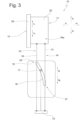
Fig. 3 eine Seitenansicht gemäßFig. 1 , wobei sich das Kopfteil in einer mittleren Position zwischen der hinteren und einer vorderen Position befindet, -
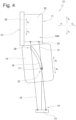
Fig. 4 eine Seitenansicht gemäßFig. 3 , wobei sich das Kopfteil in der vorderen Position befindet, -
Fig. 5 eine Seitenansicht eines zweiten Ausführungsbeispiels der erfindungsgemäßen Kopfstütze, wobei sich das Kopfteil in einer hinteren Position befindet, und wobei das Kulissenbauteil an der Haltevorrichtung bewegbar geführt ist, -
Fig. 6 eine Seitenansicht gemäßFig. 5 , wobei sich das Kopfteil in einer mittleren Position zwischen der hinteren und einer vorderen Position befindet, -
Fig. 7 eine Seitenansicht gemäßFig. 5 , wobei sich das Kopfteil in der vorderen Position befindet. -
Fig. 8 eine Seitenansicht eines dritten Ausführungsbeispiels der Kopfstütze, wobei sich das Kopfteil in einer hinteren Position befindet, und wobei das Kulissenbauteil an dem Kopfanlageteil bewegbar geführt ist, -
Fig. 9 eine Seitenansicht gemäßFig. 8 , wobei sich das Kopfteil in einer mittleren Position zwischen der hinteren und einer vorderen Position befindet, -
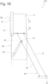
Fig. 10 eine Seitenansicht gemäßFig. 8 , wobei sich das Kopfteil in der vorderen Position befindet. -
Fig. 11 eine Seitenansicht eines vierten Ausführungsbeispiels der Kopfstütze, wobei sich das Kopfteil in der vorderen Position befindet, -
Fig. 12 eine Seitenansicht gemäßFig. 11 , wobei sich das Kopfteil in einer hinteren Position befindet.
-
Fig. 1 a side view of a first exemplary embodiment of the headrest according to the invention, with a head part being in a rear position and with a link component being movably guided on a handlebar, -
Fig. 2 a view of the headrest according to view arrow A inFig. 1 , whereby the head part is not shown completely for the sake of clarity, -
Fig. 3 a side view according toFig. 1 , with the headboard being in a middle position between the rear and a front position, -
Fig. 4 a side view according toFig. 3 , with the headboard in the forward position, -
Fig. 5 a side view of a second exemplary embodiment of the headrest according to the invention, with the head part being in a rear position and with the link component being movably guided on the holding device, -
Fig. 6 a side view according toFig. 5 , with the headboard being in a middle position between the rear and a front position, -
Fig. 7 a side view according toFig. 5 , with the headboard in the forward position. -
Fig. 8 a side view of a third exemplary embodiment of the headrest, the head part being in a rear position, and the link component being movably guided on the head rest part, -
Fig. 9 a side view according toFig. 8 , with the headboard being in a middle position between the rear and a front position, -
Fig. 10 a side view according toFig. 8 , with the headboard in the forward position. -
Fig. 11 a side view of a fourth embodiment of the headrest, with the head part in the front position, -
Fig. 12 a side view according toFig. 11 , with the headboard in a rear position.
Eine Kopfstütze gemäß einem ersten Ausführungsbeispiel insgesamt ist in den Fig. mit dem Bezugszeichen 10 bezeichnet.A headrest according to a first exemplary embodiment as a whole is designated by
Die Kopfstütze 10 umfasst gemäß
Mittels einer eine Viergelenkvorrichtung 14 umfassende Verstellvorrichtung 20 ist das Kopfteil 11 auf einer Koppelkurve in die Richtungen x1 und x2 zwischen einer ersten hinteren und einer zweiten vorderen Position bewegbar. Die Viergelenkvorrichtung 14 umfasst eine erste Lenkervorrichtung 15 sowie eine zweite Lenkervorrichtung 16. Die Lenkervorrichtung 15 bildet mit der Haltevorrichtung 33 ein Schwenkgelenk G1 mit einer Schwenkachse a1 sowie mit dem Kopfteil 11 ein Schwenkgelenk G2 mit einer Schwenkachse a2. Auch die Lenkervorrichtung 16 bildet mit der Haltevorrichtung 33 ein Schwenkgelenk G3 mit einer Schwenkachse a3 sowie mit dem Kopfteil 11 ein Schwenkgelenk G4 mit einer Schwenkachse a4.By means of an adjusting
In diesem Ausführungsbeispiel sind Längsachsen m1 und m2 der Lenkervorrichtungen 15 und 16 parallel zueinander. Gemäß einer alternativen Ausführungsform könnten die Längsachsen m1 und m2 auch derart ausgebildet sein, dass sich mit dem Halteelement 13 und dem Kopfteil 11 ein Trapezviergelenk ergibt, die Längsachsen m1 und m2 also nicht parallel sind. In diesem Fall wäre der Abstand der Gelenke G1 und G3 ungleich dem Abstand der Gelenke G2 und G4, wobei der Abstand zwischen den Gelenken G1 und G3 größer oder kleiner als der Abstand zwischen den Gelenken G2 und G4 sein kann.In this exemplary embodiment, longitudinal axes m1 and m2 of the
Die Lenkervorrichtung 15 weist zwischen den Gelenken G1 und G2 eine Länge L1 und die Lenkervorrichtung 16 misst zwischen den Gelenken G3 und G4 eine Länge L2. Im vorliegenden Ausführungsbeispiel sind die Längen L1 und L2 gleich. Die Länge L1 kann aber gemäß alternativen Ausführungen größer oder kleiner sein als die Länge L2.The
Z.B. kann die Lenkervorrichtung 15 wenigstens zwei quer zur Verstellrichtung x1 und x2 parallele Lenker 24 aufweisen (siehe
Im vorliegenden Ausführungsbeispiel umfasst das Kopfteil 11 einen hinteren Fortsatz 22, welcher mit den Lenkervorrichtungen 15 und 16 die Schwenkgelenke G2 und G4 bildet. Das Kopfteil 11 ist auf diese Weise auf einer Koppelkurve zwischen der ersten hinteren Position (siehe
Mit einer Antriebsvorrichtung 30 ist jede der definierten Relativpositionen der Viergelenkvorrichtung 14 einstellbar. Während die Verstellvorrichtung 20 bei allen beschriebenen Ausführungsbeispielen wie zuvor beschrieben ausgeführt ist, werden nachfolgend unterschiedliche erfindungswesentliche Varianten der Antriebsvorrichtungen 30, 30', 30" und 30‴ beschrieben.Each of the defined relative positions of the four-
Die Antriebsvorrichtung 30 umfasst eine Kulisse 18 mit einer Längsachse m3, an einem der Elemente der Viergelenkvorrichtung 14 sowie ein Stellelement 17, welches derart in die Kulisse 18 eingreift, dass es von der Kulisse 18 geführt werden kann. Das Stellelement 17 ist einem anderen der Elemente der Viergelenkvorrichtung 14 zugeordnet.The
Bei einem ersten in den
Grundsätzlich kann das Kulissenbauteil 19 auf einer beliebigen Bahn geführt sein. Der Einfachheit halber ist das Kulissenbauteil 19 in dem ersten Ausführungsbeispiel mittels der Führung 21 auf einer linearen Bahn geführt und bewegt sich zwischen einer primären Position und einer sekundären Position entlang einer Längsachse, die parallel zu der Längsachse m1 ist. Das Stellelement 17 greift in die Kulisse 18 ein und ist unbewegbar fest mit dem Halteelement 13 verbunden. Die Führung 21 ist lediglich in
Das Stellelement 17 bewegt sich während der Bewegung des Kulissenbauteils 19 von der primären Position in die sekundäre Position relativ zu der Kulisse 18 von einem ersten Endbereich 26 zu einem zweiten Endbereich 27 der Kulisse 18. Die Bewegung des Stellelements 17 zwischen der primären Position und der sekundären Position erfolgt, um das Kopfteil 11 von der ersten Position in die zweite Position zu bewegen.The
Im vorliegenden Beispiel ist die Kulisse 18 in einem separaten Kulissenbauteil 19 ausgebildet, welches an der Lenkervorrichtung 15 bewegbar geführt ist. Das an dem Halteelement 13 unbewegbar gehaltene Stellelement 17 greift in die Kulisse 18 ein.In the present example, the
Gemäß
Die umgekehrte Bewegung des Kulissenbauteils 19 in dem Sinne, dass sich das Stellelement 17 relativ zu der Kulisse 18 von dem zweiten Endbereich 27 zu dem ersten Endbereich 26 bewegt, hat eine Verstellung des Kopfteils 11 in Richtung x2 von der zweiten Position in die erste Position zur Folge.The reverse movement of the
Bei der Bewegung des Kopfteils 11 zwischen der ersten Position und der zweiten Position wird das Kopfteil 11 in Richtung x1 bewegt und geringfügig auch in Richtung z1 und z2 verstellt. Die Ursache dafür ist die Schwenkbewegung der Lenkervorrichtung 15 um die Schwenkachse a1 sowie die Schwenkbewegung der Lenkervorrichtung 16 um die Schwenkachse a3. Das Gelenk G2 führt daher jeweils eine Kreisbewegung um die Schwenkachse a1 und das Gelenk G4 eine Kreisbewegung um die Schwenkachse a3 aus.When moving the
Ein zweites Ausführungsbeispiel der Kopfstütze 110 ist in den
Mittels eines Antriebs 23, auf den weiter unten genauer eingegangen wird, ist die Kulisse 18 entlang einer Bewegungsbahn bewegbar, die von der Führung 21' definiert ist. Die Bewegungsbahn kann entsprechend der Erfindung eine translatorische, eine rotatorische oder auch eine gemischte Bewegung mit translatorischen und rotatorischen Anteilen sein. In diesem Ausführungsbeispiel wird die Kulisse 18' von der Führung 21' auf einer linearen Bewegungsbahn geführt. Das ermöglicht die Bewegung der Kulisse 18' mittels eines Linearantriebs.By means of a
Das an der Lenkervorrichtung 16 fest angeordnete Stellelement 17' greift in die Kulisse 18' ein, welche dem Kulissenbauteil 19' zugeordnet ist, das mit der Führung 21' an dem Halteelement 13 geführt ist.The actuating element 17 ', which is fixedly arranged on the
Bei der Bewegung des Kopfteils 11 von der ersten Position in die zweite Position und einer gleichzeitigen Bewegung des Kulissenbauteils 19' relativ zu dem Stellelement 17' von einer primären Position in eine sekundäre Position bewegt sich das Stellelement 17' innerhalb der Kulisse 18' zwischen einem ersten Endbereich 26 und einem zweiten Endbereich 27 und zwingt dabei die Viergelenkvorrichtung 14 in bestimmte Positionen.When the
Gemäß
Wird das Kulissenbauteil 19' in Richtung q2 von der sekundären Position in die primäre Position bewegt, verlagert sich das Kopfteil von der zweiten Position in die erste Position.If the link component 19' is moved in the direction q2 from the secondary position to the primary position, the head part shifts from the second position to the first position.
Ein drittes Ausführungsbeispiel der Kopfstütze 210 ist in den
Abweichend von den vorbeschriebenen Ausführungsbeispielen sind alternativ andere Konstellationen der Antriebsvorrichtungen 30, 30' und 30" möglich.Deviating from the previously described exemplary embodiments, other constellations of the
Z.B. sind in Abwandlung des ersten Ausführungsbeispiels nachfolgend aufgeführte Konstellationen möglich.For example, as a modification of the first exemplary embodiment, the constellations listed below are possible.
Alternativ zu dem ersten Ausführungsbeispiel könnte das Stellelement 17 auch an dem Kopfteil 11 gehalten sein und relativ zu diesem unbewegbar sein. Gemäß einer weiteren Alternative könnte das Kulissenbauteil 19 bewegbar an dem Lenker 16 bewegbar geführt sein und das Stellelement 17 ist fest mit dem Halteelement 13 oder an dem Kopfteil 11 verbunden. Die übrigen Merkmale dieser Abwandlungen entsprechen denen des ersten Ausführungsbeispiels.As an alternative to the first exemplary embodiment, the adjusting
In Abwandlung des zweiten Ausführungsbeispiels sind z.B. die nachfolgenden Konstellationen möglich. Gemäß einer weiteren Ausführung ist das Kulissenbauteil 19' bewegbar an dem Halteelement 13 und das Stellelement 17' fest an der Lenkervorrichtung 15 befestigt.In a modification of the second exemplary embodiment, the following constellations are possible, for example. According to a further embodiment, the link component 19 'is movably attached to the holding
Gemäß einer weiteren alternativen Ausführung ist z.B. das Kulissenbauteil 19' bewegbar an dem Kopfteil 11 und das Stellelement 17' ist fest an einem der Lenker 15 angeordnet. Die übrigen Merkmale dieser Abwandlungen entsprechen denen des zweiten Ausführungsbeispiels.According to a further alternative embodiment, for example, the link component 19 'is movable on the
Das bewegbare Kulissenbauteil 19' kann grundsätzlich an dem Halteelement 13 oder dem Kopfteil 11 und dass Stellelement 17' fest mit einer der Lenkervorrichtungen 15 oder 16 verbunden sein.The movable link component 19 'can basically be firmly connected to the holding
Auch kann das bewegbare Kulissenbauteil 19' grundsätzlich an einer der Lenkervorrichtungen 15 oder 16 bewegbar geführt sein und das Stellelement 17' mit einem der Bauteile Haltevorrichtung 33 oder Kopfteil 11 fest verbunden sein.The movable link component 19 'can basically be movably guided on one of the
Gemäß einer weiteren alternativen Ausführung der Kopfstütze 310 mit einer Antriebsvorrichtung 30"', die in den
Bei dieser Variante ist das Halteelement 13‴ von einer schiefen Ebene gebildet, wobei in einer ersten Endposition die Verstellvorrichtung 20‴ derart positioniert ist, dass die Mittelachsen m1 und m2 der Lenker 15 und 16 rechtwinklig zu der schiefen Ebene stehen. Das hat den Vorteil, dass sich der Abstand zwischen den Lenkern 15 und 16 bei der Bewegung von der ersten Endposition in die zweite Endposition kontinuierlich verkleinert und bei der Bewegung von der zweiten Endposition in die erste Endposition kontinuierlich vergrößert. Auf diese Weise wird die Steuerung wesentlich vereinfacht. Alle anderen Bestandteile der Kopfstütze sind unverändert geblieben.In this variant, the holding
Eine Höhenverstellung des Kopfteils 11 in die Richtungen z1 und z2 kann unabhängig von der Ausführung der Antriebsvorrichtung 30, 30' und 30" und der Position der Verstellvorrichtung 20 stattfinden, indem das Halteelement 13 in die Richtungen z1 und z2 verstellbar ist. Dazu kann das Halteelement 13 mit Tragstangen versehen sein, die in rückenlehnenfesten Führungshülsen in verschiedenen Höhenpositionen z.B. mittels einer Verriegelungsvorrichtung in bekannter Weise befestigbar sind.A height adjustment of the
Alternativ oder zusätzlich kann eine Kopfanlageplatte 28 relativ zu dem Fortsatz 22 in die Richtungen v1 und v2 verstellbar an dem Fortsatz 22 geführt sein. Hierfür kann die Kopfanlageplatte 28 nicht dargestellte Führungselemente aufweisen, die mit Führungselementen an dem Fortsatz 22 zusammenwirken. Mittels einer Fixiervorrichtung ist die Kopfanlageplatte 28 z.B. in mehreren Stufen oder stufenlos in der jeweiligen Relativposition zu dem Fortsatz 22 fixierbar.Alternatively or additionally, a
Die Antriebsvorrichtung 30 umfasst z.B. einen Antrieb 23 mit einem Motor 25 und einem Getriebe 29 um das Kulissenbauteil 19' zu verlagern. Der Antrieb 23 ist nicht erfindungswesentlich, d.h., es können geeignete Elemente gewählt werden.The
Bei einer linearen Verstellung ist z.B. ein Spindelantrieb als Getriebe 29 geeignet, wobei von dem Motor 25 eine Spindel 31 oder eine Spindelmutter 32 angetrieben wird, mit welcher das Kulissenbauteil 19' verbunden ist. Z.B. wird gemäß
Ein Spindelantrieb hat z.B. den Vorteil, dass die Selbsthemmung das Kopfteil 11 in der eingestellten Position fixiert. Mit anderen Worten, es ist keine separate Verriegelungsvorrichtung zum Fixieren des Kopfteils in der eingestellten Position notwendig.A spindle drive, for example, has the advantage that the self-locking device fixes the
Ist das Kulissenbauteil 19 auf einer nicht-linearen Bahn geführt, kann z.B. ein Linearantrieb verwendet werden, welcher derart bewegbar gelagert ist, dass ein Antriebsteil dem Kulissenbauteil 19 folgen kann.If the
Um die Kräfte zu verringern, die zwischen der Kulisse 18 und dem Kulissenelement 25 wirken, können in Bezug auf alle Ausführungsbeispiele z.B. wenigstens zwei Kulissen 18, 18' oder 18" und eine entsprechende Anzahl Stellelemente 17, 17' oder 17" vorgesehen sein. Z.B. wirkt eine erste bewegbar geführte Kulisse 18' mit einem Stellelement 17' zusammen, das fest an der ersten Lenkervorrichtung 15 angeordnet ist und eine parallel zu der ersten Kulisse 18' geführte und bewegte zweite Kulisse 18' wirkt mit einem Stellelement 17' zusammen, das fest mit der zweiten Lenkervorrichtung 16 oder mit einem quer zu der Bewegungsrichtung zu dem Lenker 15 bzw. 16 versetzt angeordneten Lenker verbunden ist.In order to reduce the forces that act between the
Claims (15)
Applications Claiming Priority (1)
| Application Number | Priority Date | Filing Date | Title |
|---|---|---|---|
| DE102022122310.8A DE102022122310A1 (en) | 2022-09-02 | 2022-09-02 | headrest |
Publications (2)
| Publication Number | Publication Date |
|---|---|
| EP4331908A1 true EP4331908A1 (en) | 2024-03-06 |
| EP4331908B1 EP4331908B1 (en) | 2024-12-04 |
Family
ID=87575839
Family Applications (1)
| Application Number | Title | Priority Date | Filing Date |
|---|---|---|---|
| EP23191498.7A Active EP4331908B1 (en) | 2022-09-02 | 2023-08-15 | Headrest |
Country Status (2)
| Country | Link |
|---|---|
| EP (1) | EP4331908B1 (en) |
| DE (1) | DE102022122310A1 (en) |
Citations (6)
| Publication number | Priority date | Publication date | Assignee | Title |
|---|---|---|---|---|
| DE102010007942A1 (en) | 2010-02-12 | 2011-08-18 | Grammer AG, 92224 | Headrest for vehicle seats |
| US20170088025A1 (en) * | 2014-03-17 | 2017-03-30 | Hyundai Dymos Incorporated | Electric-powered headrest |
| DE102018109611A1 (en) * | 2018-04-10 | 2019-10-10 | Grammer Aktiengesellschaft | headrest |
| DE102018005316A1 (en) | 2018-07-05 | 2020-01-09 | Grammer Aktiengesellschaft | headrest |
| CN112977216A (en) * | 2021-03-26 | 2021-06-18 | 重庆宏立至信科技发展集团有限公司 | Electric translation headrest |
| CN113525205A (en) * | 2021-08-26 | 2021-10-22 | 延锋安道拓座椅有限公司 | A seat electric headrest |
-
2022
- 2022-09-02 DE DE102022122310.8A patent/DE102022122310A1/en active Pending
-
2023
- 2023-08-15 EP EP23191498.7A patent/EP4331908B1/en active Active
Patent Citations (7)
| Publication number | Priority date | Publication date | Assignee | Title |
|---|---|---|---|---|
| DE102010007942A1 (en) | 2010-02-12 | 2011-08-18 | Grammer AG, 92224 | Headrest for vehicle seats |
| US20170088025A1 (en) * | 2014-03-17 | 2017-03-30 | Hyundai Dymos Incorporated | Electric-powered headrest |
| DE102018109611A1 (en) * | 2018-04-10 | 2019-10-10 | Grammer Aktiengesellschaft | headrest |
| DE102018109611B4 (en) | 2018-04-10 | 2022-04-21 | Grammer Aktiengesellschaft | headrest |
| DE102018005316A1 (en) | 2018-07-05 | 2020-01-09 | Grammer Aktiengesellschaft | headrest |
| CN112977216A (en) * | 2021-03-26 | 2021-06-18 | 重庆宏立至信科技发展集团有限公司 | Electric translation headrest |
| CN113525205A (en) * | 2021-08-26 | 2021-10-22 | 延锋安道拓座椅有限公司 | A seat electric headrest |
Also Published As
| Publication number | Publication date |
|---|---|
| DE102022122310A1 (en) | 2024-03-07 |
| EP4331908B1 (en) | 2024-12-04 |
Similar Documents
| Publication | Publication Date | Title |
|---|---|---|
| DE3902979C2 (en) | Folding machine for folding roof sheets | |
| DE2844647C2 (en) | Longitudinal adjustment device for a vehicle seat, in particular a motor vehicle seat | |
| EP1243461B1 (en) | Seat base body for a vehicle seat | |
| DE102015013362B4 (en) | Headrest for a vehicle seat | |
| WO2014001013A1 (en) | Adjustment device for adjusting the position of a windscreen | |
| EP3552874B1 (en) | Vehicle seat with adjustable switching bracket | |
| EP3789237B1 (en) | Vehicle seat with longitudinal adjustment device and rotation adjustment device | |
| DE3603557A1 (en) | CONTROL AND OPERATING DEVICE FOR VEHICLES | |
| DE69127909T2 (en) | Sliding-lifting roof device for motor vehicles | |
| DE4305909C2 (en) | Adjustable motor vehicle headrest | |
| DE102018109611B4 (en) | headrest | |
| DE3336349A1 (en) | Backrest with adjustable back support | |
| EP1064163A1 (en) | Wind-stopping device | |
| DE3941875A1 (en) | Windscreen positioner with guide rails for motorcycleA - incorporates lever with pivoted connections to unequally inclined rails superimposing forward rotary movement on upward displacement | |
| EP0437283A1 (en) | Sliding roof for vehicles | |
| DE2920684C2 (en) | Bracket and drive device for turning bars in printing machines | |
| DE19838281C1 (en) | Height adjustable armrest for motor vehicles | |
| EP0602361A2 (en) | Backrest articulation for vehicle seat | |
| EP4331908B1 (en) | Headrest | |
| EP1729037A1 (en) | Friction ring transmission | |
| DE19521883C2 (en) | Vehicle seat | |
| DE19735492A1 (en) | Coaxial drive for the microscope stage | |
| DE102018108795B4 (en) | Vehicle seat with adjustable control console | |
| DE102021134096B4 (en) | Equipment part for a vehicle | |
| DE2856937A1 (en) | Servo drive for seat setting - incorporates two separate drives for rack and tilt cam adjustments |
Legal Events
| Date | Code | Title | Description |
|---|---|---|---|
| PUAI | Public reference made under article 153(3) epc to a published international application that has entered the european phase |
Free format text: ORIGINAL CODE: 0009012 |
|
| STAA | Information on the status of an ep patent application or granted ep patent |
Free format text: STATUS: THE APPLICATION HAS BEEN PUBLISHED |
|
| STAA | Information on the status of an ep patent application or granted ep patent |
Free format text: STATUS: REQUEST FOR EXAMINATION WAS MADE |
|
| AK | Designated contracting states |
Kind code of ref document: A1 Designated state(s): AL AT BE BG CH CY CZ DE DK EE ES FI FR GB GR HR HU IE IS IT LI LT LU LV MC ME MK MT NL NO PL PT RO RS SE SI SK SM TR |
|
| 17P | Request for examination filed |
Effective date: 20240216 |
|
| RBV | Designated contracting states (corrected) |
Designated state(s): AL AT BE BG CH CY CZ DE DK EE ES FI FR GB GR HR HU IE IS IT LI LT LU LV MC ME MK MT NL NO PL PT RO RS SE SI SK SM TR |
|
| GRAP | Despatch of communication of intention to grant a patent |
Free format text: ORIGINAL CODE: EPIDOSNIGR1 |
|
| STAA | Information on the status of an ep patent application or granted ep patent |
Free format text: STATUS: GRANT OF PATENT IS INTENDED |
|
| RIC1 | Information provided on ipc code assigned before grant |
Ipc: B60N 2/865 20180101ALI20240628BHEP Ipc: B60N 2/809 20180101ALI20240628BHEP Ipc: B60N 2/02 20060101AFI20240628BHEP |
|
| INTG | Intention to grant announced |
Effective date: 20240801 |
|
| P01 | Opt-out of the competence of the unified patent court (upc) registered |
Free format text: CASE NUMBER: APP_50424/2024 Effective date: 20240905 |
|
| GRAS | Grant fee paid |
Free format text: ORIGINAL CODE: EPIDOSNIGR3 |
|
| GRAA | (expected) grant |
Free format text: ORIGINAL CODE: 0009210 |
|
| STAA | Information on the status of an ep patent application or granted ep patent |
Free format text: STATUS: THE PATENT HAS BEEN GRANTED |
|
| AK | Designated contracting states |
Kind code of ref document: B1 Designated state(s): AL AT BE BG CH CY CZ DE DK EE ES FI FR GB GR HR HU IE IS IT LI LT LU LV MC ME MK MT NL NO PL PT RO RS SE SI SK SM TR |
|
| REG | Reference to a national code |
Ref country code: CH Ref legal event code: EP |
|
| REG | Reference to a national code |
Ref country code: DE Ref legal event code: R096 Ref document number: 502023000361 Country of ref document: DE |
|
| REG | Reference to a national code |
Ref country code: IE Ref legal event code: FG4D Free format text: LANGUAGE OF EP DOCUMENT: GERMAN |
|
| REG | Reference to a national code |
Ref country code: LT Ref legal event code: MG9D |
|
| REG | Reference to a national code |
Ref country code: NL Ref legal event code: MP Effective date: 20241204 |
|
| PG25 | Lapsed in a contracting state [announced via postgrant information from national office to epo] |
Ref country code: HR Free format text: LAPSE BECAUSE OF FAILURE TO SUBMIT A TRANSLATION OF THE DESCRIPTION OR TO PAY THE FEE WITHIN THE PRESCRIBED TIME-LIMIT Effective date: 20241204 |
|
| PG25 | Lapsed in a contracting state [announced via postgrant information from national office to epo] |
Ref country code: FI Free format text: LAPSE BECAUSE OF FAILURE TO SUBMIT A TRANSLATION OF THE DESCRIPTION OR TO PAY THE FEE WITHIN THE PRESCRIBED TIME-LIMIT Effective date: 20241204 |
|
| PG25 | Lapsed in a contracting state [announced via postgrant information from national office to epo] |
Ref country code: BG Free format text: LAPSE BECAUSE OF FAILURE TO SUBMIT A TRANSLATION OF THE DESCRIPTION OR TO PAY THE FEE WITHIN THE PRESCRIBED TIME-LIMIT Effective date: 20241204 |
|
| PG25 | Lapsed in a contracting state [announced via postgrant information from national office to epo] |
Ref country code: ES Free format text: LAPSE BECAUSE OF FAILURE TO SUBMIT A TRANSLATION OF THE DESCRIPTION OR TO PAY THE FEE WITHIN THE PRESCRIBED TIME-LIMIT Effective date: 20241204 |
|
| PG25 | Lapsed in a contracting state [announced via postgrant information from national office to epo] |
Ref country code: NO Free format text: LAPSE BECAUSE OF FAILURE TO SUBMIT A TRANSLATION OF THE DESCRIPTION OR TO PAY THE FEE WITHIN THE PRESCRIBED TIME-LIMIT Effective date: 20250304 |
|
| PG25 | Lapsed in a contracting state [announced via postgrant information from national office to epo] |
Ref country code: GR Free format text: LAPSE BECAUSE OF FAILURE TO SUBMIT A TRANSLATION OF THE DESCRIPTION OR TO PAY THE FEE WITHIN THE PRESCRIBED TIME-LIMIT Effective date: 20250305 Ref country code: LV Free format text: LAPSE BECAUSE OF FAILURE TO SUBMIT A TRANSLATION OF THE DESCRIPTION OR TO PAY THE FEE WITHIN THE PRESCRIBED TIME-LIMIT Effective date: 20241204 |
|
| PG25 | Lapsed in a contracting state [announced via postgrant information from national office to epo] |
Ref country code: RS Free format text: LAPSE BECAUSE OF FAILURE TO SUBMIT A TRANSLATION OF THE DESCRIPTION OR TO PAY THE FEE WITHIN THE PRESCRIBED TIME-LIMIT Effective date: 20250304 |
|
| PG25 | Lapsed in a contracting state [announced via postgrant information from national office to epo] |
Ref country code: NL Free format text: LAPSE BECAUSE OF FAILURE TO SUBMIT A TRANSLATION OF THE DESCRIPTION OR TO PAY THE FEE WITHIN THE PRESCRIBED TIME-LIMIT Effective date: 20241204 |
|
| PG25 | Lapsed in a contracting state [announced via postgrant information from national office to epo] |
Ref country code: SM Free format text: LAPSE BECAUSE OF FAILURE TO SUBMIT A TRANSLATION OF THE DESCRIPTION OR TO PAY THE FEE WITHIN THE PRESCRIBED TIME-LIMIT Effective date: 20241204 |
|
| PG25 | Lapsed in a contracting state [announced via postgrant information from national office to epo] |
Ref country code: PL Free format text: LAPSE BECAUSE OF FAILURE TO SUBMIT A TRANSLATION OF THE DESCRIPTION OR TO PAY THE FEE WITHIN THE PRESCRIBED TIME-LIMIT Effective date: 20241204 |
|
| PG25 | Lapsed in a contracting state [announced via postgrant information from national office to epo] |
Ref country code: IS Free format text: LAPSE BECAUSE OF FAILURE TO SUBMIT A TRANSLATION OF THE DESCRIPTION OR TO PAY THE FEE WITHIN THE PRESCRIBED TIME-LIMIT Effective date: 20250404 |
|
| PG25 | Lapsed in a contracting state [announced via postgrant information from national office to epo] |
Ref country code: PT Free format text: LAPSE BECAUSE OF FAILURE TO SUBMIT A TRANSLATION OF THE DESCRIPTION OR TO PAY THE FEE WITHIN THE PRESCRIBED TIME-LIMIT Effective date: 20250404 |
|
| PG25 | Lapsed in a contracting state [announced via postgrant information from national office to epo] |
Ref country code: EE Free format text: LAPSE BECAUSE OF FAILURE TO SUBMIT A TRANSLATION OF THE DESCRIPTION OR TO PAY THE FEE WITHIN THE PRESCRIBED TIME-LIMIT Effective date: 20241204 |
|
| PG25 | Lapsed in a contracting state [announced via postgrant information from national office to epo] |
Ref country code: RO Free format text: LAPSE BECAUSE OF FAILURE TO SUBMIT A TRANSLATION OF THE DESCRIPTION OR TO PAY THE FEE WITHIN THE PRESCRIBED TIME-LIMIT Effective date: 20241204 |
|
| PG25 | Lapsed in a contracting state [announced via postgrant information from national office to epo] |
Ref country code: SK Free format text: LAPSE BECAUSE OF FAILURE TO SUBMIT A TRANSLATION OF THE DESCRIPTION OR TO PAY THE FEE WITHIN THE PRESCRIBED TIME-LIMIT Effective date: 20241204 |
|
| PG25 | Lapsed in a contracting state [announced via postgrant information from national office to epo] |
Ref country code: CZ Free format text: LAPSE BECAUSE OF FAILURE TO SUBMIT A TRANSLATION OF THE DESCRIPTION OR TO PAY THE FEE WITHIN THE PRESCRIBED TIME-LIMIT Effective date: 20241204 |
|
| PG25 | Lapsed in a contracting state [announced via postgrant information from national office to epo] |
Ref country code: IT Free format text: LAPSE BECAUSE OF FAILURE TO SUBMIT A TRANSLATION OF THE DESCRIPTION OR TO PAY THE FEE WITHIN THE PRESCRIBED TIME-LIMIT Effective date: 20241204 |
|
| REG | Reference to a national code |
Ref country code: DE Ref legal event code: R097 Ref document number: 502023000361 Country of ref document: DE |
|
| PG25 | Lapsed in a contracting state [announced via postgrant information from national office to epo] |
Ref country code: SE Free format text: LAPSE BECAUSE OF FAILURE TO SUBMIT A TRANSLATION OF THE DESCRIPTION OR TO PAY THE FEE WITHIN THE PRESCRIBED TIME-LIMIT Effective date: 20241204 |
|
| PG25 | Lapsed in a contracting state [announced via postgrant information from national office to epo] |
Ref country code: DK Free format text: LAPSE BECAUSE OF FAILURE TO SUBMIT A TRANSLATION OF THE DESCRIPTION OR TO PAY THE FEE WITHIN THE PRESCRIBED TIME-LIMIT Effective date: 20241204 |
|
| PGFP | Annual fee paid to national office [announced via postgrant information from national office to epo] |
Ref country code: DE Payment date: 20250819 Year of fee payment: 3 |
|
| PLBE | No opposition filed within time limit |
Free format text: ORIGINAL CODE: 0009261 |
|
| STAA | Information on the status of an ep patent application or granted ep patent |
Free format text: STATUS: NO OPPOSITION FILED WITHIN TIME LIMIT |
|
| PGFP | Annual fee paid to national office [announced via postgrant information from national office to epo] |
Ref country code: FR Payment date: 20250821 Year of fee payment: 3 Ref country code: AT Payment date: 20251020 Year of fee payment: 3 |
|
| 26N | No opposition filed |
Effective date: 20250905 |
|
| PG25 | Lapsed in a contracting state [announced via postgrant information from national office to epo] |
Ref country code: MC Free format text: LAPSE BECAUSE OF FAILURE TO SUBMIT A TRANSLATION OF THE DESCRIPTION OR TO PAY THE FEE WITHIN THE PRESCRIBED TIME-LIMIT Effective date: 20241204 |
|
| PG25 | Lapsed in a contracting state [announced via postgrant information from national office to epo] |
Ref country code: LU Free format text: LAPSE BECAUSE OF NON-PAYMENT OF DUE FEES Effective date: 20250815 |