EP4331861A1 - Radlagereinheit für ein kraftfahrzeug sowie kraftfahrzeug - Google Patents
Radlagereinheit für ein kraftfahrzeug sowie kraftfahrzeug Download PDFInfo
- Publication number
- EP4331861A1 EP4331861A1 EP23185492.8A EP23185492A EP4331861A1 EP 4331861 A1 EP4331861 A1 EP 4331861A1 EP 23185492 A EP23185492 A EP 23185492A EP 4331861 A1 EP4331861 A1 EP 4331861A1
- Authority
- EP
- European Patent Office
- Prior art keywords
- toothing
- wheel hub
- wheel
- bearing unit
- internal toothing
- Prior art date
- Legal status (The legal status is an assumption and is not a legal conclusion. Google has not performed a legal analysis and makes no representation as to the accuracy of the status listed.)
- Granted
Links
Images


Classifications
-
- B—PERFORMING OPERATIONS; TRANSPORTING
- B60—VEHICLES IN GENERAL
- B60B—VEHICLE WHEELS; CASTORS; AXLES FOR WHEELS OR CASTORS; INCREASING WHEEL ADHESION
- B60B27/00—Hubs
-
- B—PERFORMING OPERATIONS; TRANSPORTING
- B60—VEHICLES IN GENERAL
- B60B—VEHICLE WHEELS; CASTORS; AXLES FOR WHEELS OR CASTORS; INCREASING WHEEL ADHESION
- B60B27/00—Hubs
- B60B27/001—Hubs with roller-bearings
-
- B—PERFORMING OPERATIONS; TRANSPORTING
- B60—VEHICLES IN GENERAL
- B60B—VEHICLE WHEELS; CASTORS; AXLES FOR WHEELS OR CASTORS; INCREASING WHEEL ADHESION
- B60B27/00—Hubs
- B60B27/0005—Hubs with ball bearings
-
- B—PERFORMING OPERATIONS; TRANSPORTING
- B60—VEHICLES IN GENERAL
- B60B—VEHICLE WHEELS; CASTORS; AXLES FOR WHEELS OR CASTORS; INCREASING WHEEL ADHESION
- B60B27/00—Hubs
- B60B27/0015—Hubs for driven wheels
- B60B27/0021—Hubs for driven wheels characterised by torque transmission means from drive axle
- B60B27/0026—Hubs for driven wheels characterised by torque transmission means from drive axle of the radial type, e.g. splined key
-
- B—PERFORMING OPERATIONS; TRANSPORTING
- B60—VEHICLES IN GENERAL
- B60B—VEHICLE WHEELS; CASTORS; AXLES FOR WHEELS OR CASTORS; INCREASING WHEEL ADHESION
- B60B27/00—Hubs
- B60B27/0078—Hubs characterised by the fixation of bearings
-
- B—PERFORMING OPERATIONS; TRANSPORTING
- B60—VEHICLES IN GENERAL
- B60B—VEHICLE WHEELS; CASTORS; AXLES FOR WHEELS OR CASTORS; INCREASING WHEEL ADHESION
- B60B27/00—Hubs
- B60B27/0094—Hubs one or more of the bearing races are formed by the hub
-
- B—PERFORMING OPERATIONS; TRANSPORTING
- B60—VEHICLES IN GENERAL
- B60B—VEHICLE WHEELS; CASTORS; AXLES FOR WHEELS OR CASTORS; INCREASING WHEEL ADHESION
- B60B27/00—Hubs
- B60B27/06—Hubs adapted to be fixed on axle
-
- B—PERFORMING OPERATIONS; TRANSPORTING
- B60—VEHICLES IN GENERAL
- B60B—VEHICLE WHEELS; CASTORS; AXLES FOR WHEELS OR CASTORS; INCREASING WHEEL ADHESION
- B60B35/00—Axle units; Parts thereof ; Arrangements for lubrication of axles
- B60B35/12—Torque-transmitting axles
- B60B35/121—Power-transmission from drive shaft to hub
-
- F—MECHANICAL ENGINEERING; LIGHTING; HEATING; WEAPONS; BLASTING
- F16—ENGINEERING ELEMENTS AND UNITS; GENERAL MEASURES FOR PRODUCING AND MAINTAINING EFFECTIVE FUNCTIONING OF MACHINES OR INSTALLATIONS; THERMAL INSULATION IN GENERAL
- F16C—SHAFTS; FLEXIBLE SHAFTS; ELEMENTS OR CRANKSHAFT MECHANISMS; ROTARY BODIES OTHER THAN GEARING ELEMENTS; BEARINGS
- F16C19/00—Bearings with rolling contact, for exclusively rotary movement
- F16C19/02—Bearings with rolling contact, for exclusively rotary movement with bearing balls essentially of the same size in one or more circular rows
- F16C19/14—Bearings with rolling contact, for exclusively rotary movement with bearing balls essentially of the same size in one or more circular rows for both radial and axial load
- F16C19/18—Bearings with rolling contact, for exclusively rotary movement with bearing balls essentially of the same size in one or more circular rows for both radial and axial load with two or more rows of balls
- F16C19/181—Bearings with rolling contact, for exclusively rotary movement with bearing balls essentially of the same size in one or more circular rows for both radial and axial load with two or more rows of balls with angular contact
-
- F—MECHANICAL ENGINEERING; LIGHTING; HEATING; WEAPONS; BLASTING
- F16—ENGINEERING ELEMENTS AND UNITS; GENERAL MEASURES FOR PRODUCING AND MAINTAINING EFFECTIVE FUNCTIONING OF MACHINES OR INSTALLATIONS; THERMAL INSULATION IN GENERAL
- F16C—SHAFTS; FLEXIBLE SHAFTS; ELEMENTS OR CRANKSHAFT MECHANISMS; ROTARY BODIES OTHER THAN GEARING ELEMENTS; BEARINGS
- F16C19/00—Bearings with rolling contact, for exclusively rotary movement
- F16C19/02—Bearings with rolling contact, for exclusively rotary movement with bearing balls essentially of the same size in one or more circular rows
- F16C19/14—Bearings with rolling contact, for exclusively rotary movement with bearing balls essentially of the same size in one or more circular rows for both radial and axial load
- F16C19/18—Bearings with rolling contact, for exclusively rotary movement with bearing balls essentially of the same size in one or more circular rows for both radial and axial load with two or more rows of balls
- F16C19/181—Bearings with rolling contact, for exclusively rotary movement with bearing balls essentially of the same size in one or more circular rows for both radial and axial load with two or more rows of balls with angular contact
- F16C19/183—Bearings with rolling contact, for exclusively rotary movement with bearing balls essentially of the same size in one or more circular rows for both radial and axial load with two or more rows of balls with angular contact with two rows at opposite angles
- F16C19/184—Bearings with rolling contact, for exclusively rotary movement with bearing balls essentially of the same size in one or more circular rows for both radial and axial load with two or more rows of balls with angular contact with two rows at opposite angles in O-arrangement
- F16C19/186—Bearings with rolling contact, for exclusively rotary movement with bearing balls essentially of the same size in one or more circular rows for both radial and axial load with two or more rows of balls with angular contact with two rows at opposite angles in O-arrangement with three raceways provided integrally on parts other than race rings, e.g. third generation hubs
-
- F—MECHANICAL ENGINEERING; LIGHTING; HEATING; WEAPONS; BLASTING
- F16—ENGINEERING ELEMENTS AND UNITS; GENERAL MEASURES FOR PRODUCING AND MAINTAINING EFFECTIVE FUNCTIONING OF MACHINES OR INSTALLATIONS; THERMAL INSULATION IN GENERAL
- F16C—SHAFTS; FLEXIBLE SHAFTS; ELEMENTS OR CRANKSHAFT MECHANISMS; ROTARY BODIES OTHER THAN GEARING ELEMENTS; BEARINGS
- F16C35/00—Rigid support of bearing units; Housings, e.g. caps, covers
- F16C35/04—Rigid support of bearing units; Housings, e.g. caps, covers in the case of ball or roller bearings
- F16C35/06—Mounting or dismounting of ball or roller bearings; Fixing them onto shaft or in housing
- F16C35/063—Fixing them on the shaft
- F16C35/0635—Fixing them on the shaft the bore of the inner ring being of special non-cylindrical shape which co-operates with a complementary shape on the shaft, e.g. teeth, polygonal sections
-
- B—PERFORMING OPERATIONS; TRANSPORTING
- B60—VEHICLES IN GENERAL
- B60B—VEHICLE WHEELS; CASTORS; AXLES FOR WHEELS OR CASTORS; INCREASING WHEEL ADHESION
- B60B2900/00—Purpose of invention
- B60B2900/20—Avoidance of
- B60B2900/212—Damage
-
- B—PERFORMING OPERATIONS; TRANSPORTING
- B60—VEHICLES IN GENERAL
- B60B—VEHICLE WHEELS; CASTORS; AXLES FOR WHEELS OR CASTORS; INCREASING WHEEL ADHESION
- B60B2900/00—Purpose of invention
- B60B2900/30—Increase in
- B60B2900/313—Resiliency
-
- B—PERFORMING OPERATIONS; TRANSPORTING
- B60—VEHICLES IN GENERAL
- B60B—VEHICLE WHEELS; CASTORS; AXLES FOR WHEELS OR CASTORS; INCREASING WHEEL ADHESION
- B60B2900/00—Purpose of invention
- B60B2900/30—Increase in
- B60B2900/321—Lifetime
-
- B—PERFORMING OPERATIONS; TRANSPORTING
- B60—VEHICLES IN GENERAL
- B60B—VEHICLE WHEELS; CASTORS; AXLES FOR WHEELS OR CASTORS; INCREASING WHEEL ADHESION
- B60B35/00—Axle units; Parts thereof ; Arrangements for lubrication of axles
- B60B35/12—Torque-transmitting axles
- B60B35/14—Torque-transmitting axles composite or split, e.g. half- axles; Couplings between axle parts or sections
-
- F—MECHANICAL ENGINEERING; LIGHTING; HEATING; WEAPONS; BLASTING
- F16—ENGINEERING ELEMENTS AND UNITS; GENERAL MEASURES FOR PRODUCING AND MAINTAINING EFFECTIVE FUNCTIONING OF MACHINES OR INSTALLATIONS; THERMAL INSULATION IN GENERAL
- F16C—SHAFTS; FLEXIBLE SHAFTS; ELEMENTS OR CRANKSHAFT MECHANISMS; ROTARY BODIES OTHER THAN GEARING ELEMENTS; BEARINGS
- F16C2226/00—Joining parts; Fastening; Assembling or mounting parts
- F16C2226/50—Positive connections
- F16C2226/80—Positive connections with splines, serrations or similar profiles to prevent movement between joined parts
-
- F—MECHANICAL ENGINEERING; LIGHTING; HEATING; WEAPONS; BLASTING
- F16—ENGINEERING ELEMENTS AND UNITS; GENERAL MEASURES FOR PRODUCING AND MAINTAINING EFFECTIVE FUNCTIONING OF MACHINES OR INSTALLATIONS; THERMAL INSULATION IN GENERAL
- F16C—SHAFTS; FLEXIBLE SHAFTS; ELEMENTS OR CRANKSHAFT MECHANISMS; ROTARY BODIES OTHER THAN GEARING ELEMENTS; BEARINGS
- F16C2326/00—Articles relating to transporting
- F16C2326/01—Parts of vehicles in general
- F16C2326/02—Wheel hubs or castors
Definitions
- the invention relates to a wheel bearing unit for a motor vehicle according to the type specified in the preamble of patent claim 1 and a motor vehicle according to the type specified in the preamble of patent claim 10.
- the generic one DE 10 2004 054 907 A1 discloses a wheel bearing unit, according to which a wheel hub having internal teeth is rotatably mounted via a roller bearing in relation to a wheel bearing housing. A number of the rolling elements of the rolling bearing are guided in a bearing inner ring, which is designed as a separate component from the wheel hub and is firmly connected to it.
- a known problem is that high notch stresses occur in the tooth base of the internal toothing in the area of the bearing inner ring, which can lead to tooth cracks in the internal toothing of the wheel hub and thus to early destruction of the wheel hub and ultimately to failure of the wheel bearing unit.
- the invention is based on the object of developing a wheel bearing unit according to the type specified in the preamble of claim 1 in such a way that the occurrence of tooth cracks is avoided and thus an increased service life of the wheel bearing unit is ensured.
- the wheel bearing unit comprises a wheel bearing housing, a roller bearing and a wheel hub, which has a through opening with internal teeth, via which the wheel hub can be connected in a rotationally fixed manner to a drive pin of a cardan shaft which has external teeth.
- the rolling bearing via which the wheel hub is rotatably mounted in relation to the wheel bearing housing, comprises in a known manner at least one series of rolling elements which are guided on the wheel hub side in an inner bearing ring which is designed as a separate component in relation to the wheel hub and is firmly connected to the wheel hub.
- the internal toothing has a tooth-free section, which divides the internal toothing into a first toothing area and a second toothing area spaced therefrom in the axial direction a and which is positioned such that the tooth-free section lies radially opposite to the bearing-inside end face of the bearing inner ring.
- the tooth-free section provided according to the invention and its positioning radially opposite to the bearing-inside end face of the bearing inner ring of the rolling bearing has the effect that local notch stresses in the tooth base of the internal toothing are minimized. This means that it is now advantageously ensured that - since the notch stresses leading to tooth cracks are reduced - an increased service life of the wheel hub and thus of the wheel bearing unit is ensured.
- the tooth-free section is preferably designed in the form of a freely turned area or an undercut - introduced into the through opening of the wheel hub before tooth broaching.
- the diameter D Ab of the tooth-free section should preferably be chosen such that the following applies to it: 1 ⁇ D Away D F ⁇ 1.2 where D F denotes the root diameter of the internal toothing or the toothing sections of the internal toothing.
- a further preferred embodiment is characterized in that the through opening of the wheel hub, in addition to the support area formed by the internal toothing, i.e. the first and first toothing sections as well as the tooth-free section arranged between the two toothing sections, also has a fastening area which has a contact shoulder and a - in axial Viewed in direction a - comprises the intermediate area arranged between the supporting area and the fastening area, and that based on the root diameter D F , the intermediate area has an intermediate area diameter Dz, for which the following applies: D Z D F > 1
- this also ensures in particular that when broaching gears, the corresponding broaching tool only engages in the area of the supporting area, so that the load on the broaching tool is also significantly reduced.
- the intermediate region diameter Dz is larger than the diameter D Ab of the tooth-free section of the internal toothing or is the same size as the diameter D Ab .
- the fastening area preferably has a fastening area diameter D B , for which the following applies in relation to the root diameter D F : D b D F > 1.2
- a further preferred embodiment provides that - viewed in the axial direction a - the tooth-free section has an axial section length L Ab , for which applies 0.1 ⁇ L Away L In ⁇ 0.3 where L In denotes the axial length of the internal toothing.
- the dimensioning according to the above regulation proves to be particularly advantageous since, on the one hand, a length of the tooth-free section that is sufficient for the intended reduction in the notch stress is ensured and, on the other hand, the upper limit also ensures that the toothed sections have a sufficient toothed length for torque transmission.
- the intermediate region has an intermediate region length Lz, for which the following applies in relation to the length L in the internal toothing: 0.5 ⁇ L Z L In ⁇ 0.7
- a further, advantageous embodiment of the wheel bearing unit is characterized in that - viewed in the axial direction a - the fastening area has a fastening area length L B , for which the following applies in relation to the length L in the internal toothing: 0.3 ⁇ L b L In ⁇ 0.6
- the invention is further based on the object of developing a motor vehicle which includes a wheel bearing unit in such a way that low-wear operation is ensured.
- wheel bearing unit according to the invention can be transferred analogously to the motor vehicle according to the invention, so that the advantages mentioned above can also be achieved with this.
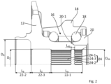
- Fig. 1 shows a wheel bearing unit for a motor vehicle, designated overall by reference number 10.
- the wheel bearing unit 10 includes a wheel hub 12, a wheel bearing housing 14 and a rolling bearing 16, via which the wheel hub 12 is rotatably mounted in relation to the wheel bearing housing 14.
- the rolling bearing 16 has two rows of rolling elements 18. While the - in Fig. 1 - left row of rolling elements 18 roll in a running surface formed in the wheel hub 12, the right row of rolling elements 18 is guided in a bearing inner ring 20 which has a corresponding running surface and is firmly connected to the wheel hub 12.
- the wheel hub 12 also has a through opening 22, which is partially provided with internal teeth 24. Via the internal toothing 24, the wheel hub 12 can be connected in a known manner in a rotationally fixed manner to a drive pin of a joint source - not shown here for reasons of clarity - which has an external toothing designed to correspond to the internal toothing 24.
- the reference symbol Dz below denotes the root circle diameter of the internal toothing 24.
- the disadvantage of the prior art is that as a result of the local material taper of the wheel hub 12 caused by the bearing inner ring 20, particularly in the area of the transition to the bearing inner end face 20-1 of the bearing inner ring 20, high notch stresses occur in the tooth base of the internal toothing 24, which in turn This can lead to tooth cracks in the internal toothing 24 and thus cause early failure of the wheel hub 12 or the wheel bearing unit 10.
- the internal toothing 24 has a first toothing section 24-1, a second toothing section 24-2 and, viewed in the axial direction a, between The two toothing sections 24-1, 24-2 lying on the two toothing sections 24-1, 24-2 are designed to have a tooth-free section 24-3 which separates the two toothing sections 24-1, 24-2 from one another.
- Fig. 2 and particularly Fig. 3 can also be seen - the sections 24-1, 24-2, 24-3 forming the internal toothing 24 are arranged and dimensioned in such a way that, viewed in the axial direction a, the tooth-free section 24-3 is radially opposite to the end face 20-1 of the bearing inner ring on the inside of the bearing 20 is positioned.
- the tooth-free section 24-3 is in the present case designed in the form of an undercut or freely turned area introduced into the through opening 22, and has a diameter D Ab , which in the present case is 10% larger than the root diameter D F of the internal toothing 24.
- the tooth-free section 24-3 in the present case is dimensioned such that it has an axial length L Ab which corresponds to 10% to 30% of the total length L In of the internal toothing 24, see Fig. 2 and Fig. 3 .
- the through opening 22 of the wheel hub 12 has, in addition to the area forming the internal toothing 24, hereinafter also referred to as the support area 22-1, a designated fastening area 22-2, and one - viewed in the axial direction a - between the support area 22 -1 and the fastening area 22-2 arranged intermediate area 22-3.
- the reference symbol L B denotes the axial length of the fastening region 22-2 and the reference symbol Lz denotes the axial length of the intermediate region 22-3. Accordingly, the diameter of the fastening area 22-2 is designated D B and the diameter of the intermediate area 22-3 is designated Dz, cf. Fig. 2 .
- the diameter of the intermediate region Dz is larger than the root diameter D F of the internal toothing 24.
- the increase in diameter advantageously achieves a weight saving.
- the regions 24-3 and 24-2 can therefore advantageously be produced in one step.
- the fastening area 22-2 is dimensioned such that the fastening diameter D B is larger than the root diameter D F by a factor of 1.2. This ensures that a sufficiently large fastening shoulder 26 is available for the fastening means, such as a nut or screw, via which the wheel hub 12 is connected to the drive pin of a joint source, see Fig. 2 .
- the axial lengths L B and Lz of the areas 22-2 and 22-3 are dimensioned in this case such that the axial length L B of the fastening area 22-2 is approximately 30% to 60% of the total length L In the internal toothing 24 and the axial length Lz of the intermediate region 22-3 corresponds to approximately 50% to 70% of the total length L in the internal toothing 24.
Landscapes
- Engineering & Computer Science (AREA)
- Mechanical Engineering (AREA)
- General Engineering & Computer Science (AREA)
- Rolling Contact Bearings (AREA)
Abstract
Description
- Die Erfindung betrifft eine Radlagereinheit für ein Kraftfahrzeug gemäß der im Oberbegriff des Patentanspruches 1 angegebenen Art sowie ein Kraftfahrzeug gemäß der im Oberbegriff des Patentanspruches 10 angegebenen Art.
- Die gattungsbildende
DE 10 2004 054 907 A1 offenbart eine Radlagereinheit, gemäß der eine eine Innenverzahnung aufweisende Radnabe über ein Wälzlager drehbar in Bezug zu einem Radlagergehäuse gelagert ist. Eine Reihe der Wälzkörper des Wälzlagers ist dabei in einem Lagerinnenring geführt, welcher als ein von der Radnabe separates Bauteil ausgebildet und mit dieser fest verbunden ist. Ein bekanntes Problem dabei ist, dass im Bereich des Lagerinnenrings hohe Kerbspannungen im Zahngrund der Innenverzahnung auftreten, die zu Verzahnungsrissen in der Innenverzahnung der Radnabe und damit zu einer frühzeitigen Zerstörung der Radnabe und letztendlich zum Ausfall der Radlagereinheit führen können. - Der Erfindung liegt die Aufgabe zugrunde eine Radlagereinheit gemäß der im Oberbegriff des Patentanspruches 1 angegebenen Art derart weiterzubilden, dass ein Auftreten von Verzahnungsrissen vermieden wird und damit eine erhöhte Lebensdauer der Radlagereinheit sichergestellt ist.
- Diese Aufgabe wird durch die kennzeichnenden Merkmale des Patentanspruches 1 in Verbindung mit seinen Oberbegriffsmerkmalen gelöst.
- Die Unteransprüche 2 bis 9 bilden vorteilhafte Weiterbildungen der erfindungsgemäßen Radlagereinheit.
- In bekannter Art und Weise umfasst die Radlagereinheit ein Radlagergehäuse, ein Wälzlager und eine Radnabe, welche eine Durchgangsöffnung mit einer Innenverzahnung aufweist, über die die Radnabe mit einem eine Außenverzahnung aufweisenden Antriebszapfen einer Gelenkswelle drehfest verbindbar ist. Das Wälzlager, über das die Radnabe drehbar in Bezug zum Radlagergehäuse gelagert ist, umfasst in bekannter Art und Weise zumindest eine Reihe von Wälzkörpern, die radnabenseitig in einem in Bezug zur Radnabe als ein separates Bauteil ausgebildeten, mit der Radnabe fest verbundenen Lagerinnenring geführt sind.
- Erfindungsgemäß ist nunmehr vorgesehen, dass die Innenverzahnung einen zahnfreien Abschnitt aufweist, der die Innenverzahnung in einen ersten Verzahnungsbereich und einen in axialer Richtung a davon beabstandet zweiten Verzahnungsbereich teilt und der derart positioniert ist, dass der zahnfreie Abschnitt radial gegenüberliegend zur lagerinnenseitigen Stirnseite des Lagerinnenrings liegt.
- Der erfindungsgemäß vorgesehene zahnfreie Abschnitt und dessen Positionierung radial gegenüberliegend zur lagerinnenseitigen Stirnseite des Lagerinnenrings des Wälzlagers hat den Effekt, dass lokale Kerbspannungen im Zahngrund der Innenverzahnung minimiert werden. D.h., es ist nunmehr in vorteilhafter Weise sichergestellt, dass - da die zu Verzahnungsrissen führenden Kerbspannungen reduziert sind - eine erhöhten Lebensdauer der Radnabe und damit der Radlagereinheit sichergestellt ist.
- Zur Gewährleistung einer einfachen, kostengünstigen Herstellung ist der zahnfreie Abschnitt bevorzugt in Form eines - vor dem Verzahnungsräumen in die Durchgangsöffnung der Radnabe eingebrachten - freigedrehten Bereichs bzw. eines Freistiches ausgebildet.
- Wie erste Versuche gezeigt haben, ist dabei der Durchmesser DAb des zahnfreien Abschnitts bevorzugt so zu wählen, dass für diesen gilt:

- Eine weitere bevorzugte Ausführungsform zeichnet sich dadurch aus, dass die Durchgangsöffnung der Radnabe neben dem durch die Innenverzahnung, also den ersten und ersten Verzahnungsabschnitt sowie den zwischen den beiden Verzahnungsabschnitten angeordneten zahnfreien Abschnitt, ausgebildeten Tragbereich, noch einen eine Anlageschulter aufweisenden Befestigungsbereich sowie einen - in axialer Richtung a betrachtet - zwischen dem Tragbereich und dem Befestigungsbereich angeordneten Zwischenbereich umfasst, und dass bezogen auf den Fußkreisdurchmesser DF, der Zwischenbereich einen Zwischenbereichdurchmesser Dz aufweist, für den gilt:

- Neben der durch den vergrößerten Durchmesser erzielten Gewichtsersparnis, ist hierdurch insbesondere auch sichergestellt, dass beim Verzahnungsräumen das entsprechende Räumwerkzeug lediglich im Bereich des Tragbereichs zum Eingriff kommt, sodass auch die Belastung des Räumwerkzeugs deutlich reduziert ist.
- Vorzugsweise ist dabei vorgesehen, dass der Zwischenbereichdurchmesser Dz größer als der Durchmesser DAb des zahnfreien Abschnitts der Innenverzahnung ist oder gleich groß wie der Durchmesser DAb ist.
- Bevorzugt weist der Befestigungsbereich einen Befestigungsbereichsdurchmesser DB auf, für den bezogen auf den Fußkreisdurchmesser DF gilt:

- Hierdurch ist sichergestellt, dass eine ausreichend große Anlageschulter zur Verfügung gestellt ist.
- Eine weitere bevorzugte Ausführungsform sieht vor, dass - in axialer Richtung a betrachtet - der zahnfreie Abschnitt eine axiale Abschnittslänge LAb aufweist, für die gilt

- Die Dimensionierung gemäß obiger Vorschrift erweist sich als besonders vorteilhaft, da einerseits eine für die vorgesehene Reduzierung der Kerbspannung ausreichende Länge des zahnfreien Abschnitts sichergestellt ist und andererseits durch die Begrenzung nach oben auch gewährleistet ist, dass die Verzahnungsabschnitte eine ausreichende Verzahnungslänge zur Drehmomentübertragung aufweisen.
- Um in axialer Richtung a eine möglichst kompakte Bauform der Radlagereinheit sicherzustellen, ist gemäß einer weiteren bevorzugten Ausführungsform vorgesehen, dass - axialer Richtung a betrachtet - der Zwischenbereich eine Zwischenbereichslänge Lz aufweist, für die bezogen auf die Länge LIn der Innenverzahnung gilt:

- Eine weitere, vorteilhafte Ausführungsform der Radlagereinheit zeichnet sich dadurch aus, dass - axialer Richtung a betrachtet - der Befestigungsbereich eine Befestigungsbereichslänge LB aufweist, für die bezogen auf die Länge LIn der Innenverzahnung gilt:

- Neben einer in axialer Richtung a betrachteten kompakten Bauform, ist hierdurch insbesondere auch sichergestellt, dass ausreichender Bauraum für Befestigungsmittel vorhanden ist.
- Der Erfindung liegt des Weiteren die Aufgabe zugrunde, ein Kraftfahrzeug, welches eine Radlagereinheit umfasst, derart weiterzubilden, dass ein verschleißarmer Betrieb sichergestellt ist.
- Diese Aufgabe wird dadurch gelöst, dass die Radlagereinheit nach einem der Patentansprüche 1 bis 9 ausgebildet ist.
- Sämtliche Ausführungen zu der erfindungsgemäßen Radlagereinheit lassen sich analog auf das erfindungsgemäße Kraftfahrzeug übertragen, sodass mit diesem auch die zuvor genannten Vorteile erzielt werden.
- Weitere Vorteile und Anwendungsmöglichkeiten der Erfindung ergeben sich aus der nachfolgenden Beschreibung in Verbindung mit dem in der Zeichnung dargestellten Ausführungsbeispiel.
- In der Zeichnung bedeutet:
- Fig. 1
- eine Seitenansicht einer Radlagereinheit eines Kraftfahrzeugs nach dem Stand der Technik;
- Fig. 2
- eine erfindungsgemäße Radlagereinheit in einer Seitenansicht, und
- Fig. 3
- ein vergrößert Ausschnitt aus
Fig. 2 -
Fig. 1 zeigt eine insgesamt mit der Bezugsziffer 10 bezeichnete Radlagereinheit für ein Kraftfahrzeug. Die Radlagereinheit 10 umfasst eine Radnabe 12, ein Radlagergehäuse 14 sowie ein Wälzlager 16, über das die Radnabe 12 drehbar in Bezug zum Radlagergehäuse 14 gelagert ist. - Wie
Fig. 1 weiter zu entnehmen ist, weist das Wälzlager 16 zwei Reihen von Wälzkörpern 18 auf. Während die - inFig. 1 - linke Reihe von Wälzkörpern 18 in einer in der Radnabe 12 ausgebildeten Lauffläche abrollen, ist die rechte Reihe von Wälzkörpern 18 in einem, eine entsprechende Lauffläche aufweisenden, mit der Radnabe 12 fest verbundenen Lagerinnenring 20 geführt. - Die Radnabe 12 weist ferner eine Durchgangsöffnung 22 auf, die bereichsweise mit einer Innenverzahnung 24 versehen ist. Über die Innenverzahnung 24 ist die Radnabe 12 in bekannter Art und Weise mit einem - hier aus Gründen der Übersichtlichkeit nicht dargestellten - eine korrespondierend zur Innenverzahnung 24 ausgebildete Außenverzahnung aufweisenden Antriebszapfen einer Gelenksquelle drehfest verbindbar. Mit dem Bezugszeichen Dz ist nachfolgend der Fußkreisdurchmesser der Innenverzahnung 24 bezeichnet.
- Nachteilig an dem Stand der Technik ist, dass als Folge der durch den Lagerinnenring 20 bedingten lokalen Materialverjüngung der Radnabe 12, insbesondere im Bereich des Übergangs zur lagerinnenseitigen Stirnseite 20-1 des Lagerinnenrings 20, hohe Kerbspannungen im Zahngrund der Innenverzahnung 24 auftreten, welche wiederum zu Verzahnungsrissen in der Innenverzahnung 24 führen und damit eine frühzeitiges Versagen der Radnabe 12 bzw. der Radlagereinheit 10 bewirken können.
- Hier setzt nun die Erfindung ein:
WieFig. 2 undFig. 3 zeigen, ist nunmehr vorgesehen, dass die Innenverzahnung 24 einen ersten Verzahnungsabschnitt 24-1, einen zweiten Verzahnungsabschnitte 24-2 und einen in axialer Richtung a betrachtet zwischen den beiden Verzahnungsabschnitten 24-1, 24-2 liegenden, die beiden Verzahnungsabschnitte 24-1, 24-2 voneinander trennenden zahnfreien Abschnitt 24-3 aufweisend ausgebildet ist. - Dabei sind - wie
Fig. 2 und insbesondereFig. 3 weiter zu entnehmen ist - die die Innenverzahnung 24 bildenden Abschnitte 24-1, 24-2, 24-3 derart angeordnet und dimensioniert, dass in axialer Richtung a betrachtet, der zahnfreie Abschnitt 24-3 radial gegenüberliegend zur lagerinnenseitigen Stirnseite 20-1 des Lagerinnenrings 20 positioniert ist. - Da nunmehr im kritischen Abschnitt der Radnabe 12, also im Bereich des Übergangs zur lagerinnenseitigen Stirnseite 20-1 des Lagerinnenrings 20, die Innenverzahnung 24 zahnlos ausgebildet ist, ist in vorteilhafter Weise sichergestellt, dass die zu Verzahnungsrissen führenden lokalen Kerbspannungen reduziert sind, was sich positiv auf die Lebensdauer der Radnabe 12 und damit der Radlagereinheit 10 auswirkt.
- Der zahnfreien Abschnitt 24-3 ist vorliegend in Form eines in die Durchgangsöffnung 22 eingebrachten Freistichs bzw. freigedrehten Bereichs ausgebildet, und weist einen Durchmesser DAb, der vorliegend um 10% größer als der Fußkreisdurchmesser DF der Innenverzahnung 24 ist.
- In axialer Richtung a betrachtet ist der zahnfreie Abschnitt 24-3 vorliegend so dimensioniert, dass dieser eine axiale Länge LAb aufweist, die 10% bis 30% der Gesamtlänge LIn der Innenverzahnung 24 entspricht, siehe
Fig. 2 undFig. 3 . - Wie
Fig. 2 weiter zu entnehmen ist, weist die Durchgangsöffnung 22 der Radnabe 12 neben den die Innenverzahnung 24 bildenden Bereich, nachfolgend auch als Tragbereich 22-1 bezeichnet, einen als Befestigungsbereich 22-2 bezeichneten, sowie einen - in axialer Richtung a betrachtet - zwischen dem Tragbereich 22-1 und dem Befestigungsbereich 22-2 angeordneten Zwischenbereich 22-3 auf. - Mit dem Bezugszeichen LB ist die axiale Länge des Befestigungsbereichs 22-2 und mit dem Bezugszeichen Lz die axiale Länge des Zwischenbereichs 22-3 bezeichnet. Entsprechend ist der Durchmesser des Befestigungsbereichs 22-2 mit DB und der Durchmesser des Zwischenbereichs 22-3 mit Dz bezeichnet, vgl.
Fig. 2 . - Um bei der Herstellung der Innenverzahnung 24 der Verschleiß des Räumwerkzeugs zu minimieren, ist der Durchmesser des Zwischenbereichs Dz größer als der Fußkreisdurchmesser DF der Innenverzahnung 24. Neben dem geringeren Verschleiß wird durch die Durchmesservergrößerung noch in vorteilhafter Weise eine Gewichtsersparnis erzielt. Vorliegend ist dabei der Durchmesser Dz so gewählt, dass dieser dem Durchmesser DAb des zahnfreien Abschnitts 24-3 entspricht, d.h.

- Somit können in vorteilhafter Weise die Bereiche 24-3 und 24-2 in einem Arbeitsschritt hergestellt werden.
- Der Befestigungsbereich 22-2 ist vorliegend so dimensioniert, dass der Befestigungsdurchmesser DB um den Faktor 1,2 größer als der Fußkreisdurchmesser DF ist. Hierdurch ist sichergestellt, dass für das Befestigungsmittel, wie z.B. Mutter oder Schraube, über das die Radnabe 12 mit dem Antriebszapfen einer Gelenksquelle verbunden wird, eine ausreichend große Befestigungsschulter 26 zur Verfügung steht, siehe
Fig. 2 . - Zur Gewährleistung einer kompakten Bauform der Radlagereinheit 10 sind die axialen Länge LB und Lz der Bereiche 22-2 und 22-3 vorliegend so dimensioniert, dass die axiale Länge LB des Befestigungsbereichs 22-2 ca. 30% bis 60% der Gesamtlänge LIn der Innenverzahnung 24 und die axiale Länge Lz des Zwischenbereichs 22-3 ca. 50% bis 70% der Gesamtlänge LIn der Innenverzahnung 24 entspricht.
Claims (10)
- Radlagereinheit (10) für ein Kraftfahrzeug, umfassend eine Radnabe (12), ein Radlagergehäuse (14) sowie ein Wälzlager (16), über das die Radnabe (12) drehbar in Bezug zum Radlagergehäuse (14) gelagert ist, wobei das Wälzlager (16) zumindest eine Reihe von Wälzkörpern (18) aufweist, die radnabenseitig in einem in Bezug zur Radnabe (12) als ein separates Bauteil ausgebildeten, mit der Radnabe (12) fest verbundenen Lagerinnenring (20) geführt sind, wobei die Radnabe (12) eine Durchgangsöffnung (22) mit einer Innenverzahnung (24) aufweist, über die die Radnabe (12) mit einem eine Außenverzahnung aufweisenden Antriebszapfens drehfest verbindbar ist,
dadurch gekennzeichnet, dass
die Innenverzahnung (24) einen ersten Verzahnungsabschnitt (24-1), einen zweiten Verzahnungsabschnitt (24-2) und einen in axialer Richtung (a) betrachtet zwischen den beiden Verzahnungsabschnitten (24-1, 24-2) liegenden, die beiden Verzahnungsabschnitte (24-1, 24-2) voneinander trennenden zahnfreien Abschnitt (24-3) aufweisend ausgebildet ist, wobei der zahnfreie Abschnitt (24-3) der Innenverzahnung (24) in axialer Richtung (a) betrachtet derart angeordnet ist, dass der zahnfreie Abschnitt (24-3) radial gegenüberliegend zur lagerinnenseitigen Stirnseite (20-1) des Lagerinnenrings (20) positioniert ist. - Radlagereinheit (10) nach Anspruch 1 oder 2,
dadurch gekennzeichnet, dass
bezogen auf einen Fußkreisdurchmesser (DF) der Verzahnungsabschnitte (24-1, 24-2) der Innenverzahnung (24), der zahnfreie Abschnitt (24-3) der Innenverzahnung (24) einen Durchmesser (DAb) aufweist, für den gilt:
- Radlagereinheit (10) nach Anspruch 1 oder 2,
dadurch gekennzeichnet, dass
die Durchgangsöffnung (22) der Radnabe (12) einen die Innenverzahnung (24) aufweisenden Tragbereich (22-1), einen eine Anlageschulter (26) aufweisenden Befestigungsbereich (22-2), sowie einen - in axialer Richtung (a) betrachtet - zwischen Trag- und Befestigungsbereich (22-1, 22-2) angeordneten Zwischenbereich (22-3) umfasst, und dass bezogen auf den Fußkreisdurchmesser (DF), der Zwischenbereich (22-3) einen Zwischenbereichdurchmesser (Dz) aufweist, für den gilt:
- Radlagereinheit (10) nach Anspruch 2 und 3,
dadurch gekennzeichnet, dass
der Zwischenbereichdurchmesser (Dz) größer als oder gleich groß wie der Durchmesser (DAb) des zahnfreien Abschnitts (24-3) der Innenverzahnung (24) ist. - Radlagereinheit (10) nach Anspruch 2 und 3,
dadurch gekennzeichnet, dass
dass bezogen auf den Fußkreisdurchmesser (DF), der Befestigungsbereich (22-2) einen Befestigungsbereichdurchmesser (DB) aufweist, für den gilt:
- Radlagereinheit (10) nach Anspruch 1,
dadurch gekennzeichnet, dass
in axialer Richtung (a) betrachtet die Innenverzahnung (24) eine Länge (LIn) aufweist, und dass bezogen auf die Länge (LIn) der Innenverzahnung (24), der zahnfreie Abschnitt (22-3) eine axiale Abschnittslänge (LAb) aufweist, für die gilt:
- Radlagereinheit (10) nach Anspruch 3,
dadurch gekennzeichnet, dass
in axialer Richtung (a) betrachtet die Innenverzahnung (24) eine Länge (LIn) aufweist, und dass bezogen auf die Länge (LIn) der Innenverzahnung (24), der Zwischenbereich (22-3) eine axiale Zwischenbereichslänge (Lz) aufweist, für die gilt:
- Radlagereinheit (10) nach Anspruch 3,
dadurch gekennzeichnet, dass
in axialer Richtung (a) betrachtet die Innenverzahnung (24) eine Länge (LIn) aufweist, und dass bezogen auf die Länge (LIn) der Innenverzahnung (24), der Befestigungsbereich (22-2) eine axiale Befestigungsbereichslänge (LB) aufweist, für die gilt:
- Radlagereinheit (10) nach Anspruch 2
dadurch gekennzeichnet, dass
der zahnlose Abschnitts (24-3) der Innenverzahnung (24) in Form eines Freistichs ausgebildet ist. - Kraftfahrzeug, umfassend eine Radlagereinheit,
dadurch gekennzeichnet, dass
die Radlagereinheit nach einem der Ansprüche 1 bis 9 ausgebildet ist.
Applications Claiming Priority (1)
| Application Number | Priority Date | Filing Date | Title |
|---|---|---|---|
| DE102022121486.9A DE102022121486A1 (de) | 2022-08-25 | 2022-08-25 | Radlagereinheit für ein Kraftfahrzeug sowie Kraftfahrzeug |
Publications (2)
| Publication Number | Publication Date |
|---|---|
| EP4331861A1 true EP4331861A1 (de) | 2024-03-06 |
| EP4331861B1 EP4331861B1 (de) | 2025-12-17 |
Family
ID=87280630
Family Applications (1)
| Application Number | Title | Priority Date | Filing Date |
|---|---|---|---|
| EP23185492.8A Active EP4331861B1 (de) | 2022-08-25 | 2023-07-14 | Radlagereinheit für ein kraftfahrzeug sowie kraftfahrzeug |
Country Status (4)
| Country | Link |
|---|---|
| US (1) | US12304237B2 (de) |
| EP (1) | EP4331861B1 (de) |
| CN (1) | CN117621704A (de) |
| DE (1) | DE102022121486A1 (de) |
Citations (6)
| Publication number | Priority date | Publication date | Assignee | Title |
|---|---|---|---|---|
| US6286909B1 (en) * | 1998-02-16 | 2001-09-11 | Nsk Ltd. | Axle unit for driving a vehicle wheel |
| DE102004054907A1 (de) | 2004-11-12 | 2006-09-14 | Gkn Driveline Deutschland Gmbh | Radnaben-Gelenk-Einheit |
| JP2009234542A (ja) * | 2008-03-28 | 2009-10-15 | Jtekt Corp | 車輪用軸受装置 |
| DE102017220457A1 (de) * | 2017-11-16 | 2019-05-16 | Em-Motive Gmbh | Verzahnungsanordnung |
| US20210138834A1 (en) * | 2019-11-11 | 2021-05-13 | Audi Ag | Wheel bearing unit for a motor vehicle as well as method for producing a wheel bearing unit |
| DE102020126843A1 (de) * | 2020-10-13 | 2022-04-14 | Audi Aktiengesellschaft | Welle-Nabe-Verbindung |
Family Cites Families (4)
| Publication number | Priority date | Publication date | Assignee | Title |
|---|---|---|---|---|
| JP2001347805A (ja) * | 2000-04-05 | 2001-12-18 | Nsk Ltd | 車輪駆動用車軸ユニット |
| KR101573023B1 (ko) | 2014-04-23 | 2015-11-30 | 주식회사 일진글로벌 | 구동 휠 베어링 및 그 제조방법 |
| KR101609828B1 (ko) | 2014-05-21 | 2016-04-07 | 주식회사 일진글로벌 | 너클 및 휠 베어링 조립체 |
| KR20210033632A (ko) | 2019-09-19 | 2021-03-29 | 서한산업(주) | 차량 구동륜의 허브와 베어링 체결구조 |
-
2022
- 2022-08-25 DE DE102022121486.9A patent/DE102022121486A1/de active Pending
-
2023
- 2023-07-14 EP EP23185492.8A patent/EP4331861B1/de active Active
- 2023-07-31 US US18/362,104 patent/US12304237B2/en active Active
- 2023-08-24 CN CN202311071446.9A patent/CN117621704A/zh active Pending
Patent Citations (6)
| Publication number | Priority date | Publication date | Assignee | Title |
|---|---|---|---|---|
| US6286909B1 (en) * | 1998-02-16 | 2001-09-11 | Nsk Ltd. | Axle unit for driving a vehicle wheel |
| DE102004054907A1 (de) | 2004-11-12 | 2006-09-14 | Gkn Driveline Deutschland Gmbh | Radnaben-Gelenk-Einheit |
| JP2009234542A (ja) * | 2008-03-28 | 2009-10-15 | Jtekt Corp | 車輪用軸受装置 |
| DE102017220457A1 (de) * | 2017-11-16 | 2019-05-16 | Em-Motive Gmbh | Verzahnungsanordnung |
| US20210138834A1 (en) * | 2019-11-11 | 2021-05-13 | Audi Ag | Wheel bearing unit for a motor vehicle as well as method for producing a wheel bearing unit |
| DE102020126843A1 (de) * | 2020-10-13 | 2022-04-14 | Audi Aktiengesellschaft | Welle-Nabe-Verbindung |
Also Published As
| Publication number | Publication date |
|---|---|
| EP4331861B1 (de) | 2025-12-17 |
| US20240066918A1 (en) | 2024-02-29 |
| CN117621704A (zh) | 2024-03-01 |
| US12304237B2 (en) | 2025-05-20 |
| DE102022121486A1 (de) | 2024-03-07 |
Similar Documents
| Publication | Publication Date | Title |
|---|---|---|
| EP1429054B1 (de) | Planetengetriebestufe | |
| EP0021223B1 (de) | Druckkammgetriebe | |
| EP3591245A1 (de) | Abgedichtetes lagermodul | |
| WO2001071220A1 (de) | Getriebebaukasten | |
| DE69727590T2 (de) | Planetengetriebe | |
| EP3404294A1 (de) | Getriebe insbesondere fuer windkraftgeneratoren | |
| DE2657575A1 (de) | Parallelwellenantrieb | |
| DE102018200056A1 (de) | Planetengetriebe | |
| DE10203983B4 (de) | Getriebe | |
| DE19782293B4 (de) | Ausgleichsgetriebe- und Antriebsritzel-Baugruppe | |
| EP2646712B1 (de) | Zahnradgetriebe mit schrägverzahnung | |
| EP3828442A1 (de) | Getriebe mit einem flexiblen zahnrad | |
| DE102004023151B4 (de) | Umlaufgetriebe | |
| EP4331861B1 (de) | Radlagereinheit für ein kraftfahrzeug sowie kraftfahrzeug | |
| EP3653905B1 (de) | Exzentergetriebe | |
| DE102019212221A1 (de) | Wellgetriebe | |
| EP4403797A1 (de) | Getriebe und verwendung eines getriebes | |
| DE112022002761T5 (de) | Planetenuntersetzungsgetriebe mit mindestens einem Planetenrad mit mindestens einem Außengewindeabschnitt | |
| DE102023202319A1 (de) | Elektrischer Achsantrieb für ein Fahrzeug | |
| DE102023203391A1 (de) | Zahnscheibe | |
| DE102019212220B4 (de) | Wellgetriebe | |
| DE202018100030U1 (de) | Planetengetriebe | |
| EP2153075B1 (de) | Lager | |
| DE102017220430B3 (de) | Geteiltes Zahnrad | |
| DE102004036389B4 (de) | Turbinenschaufelfuß mit Mehrfachradiusnut für eine axiale Schaufelbefestigung |
Legal Events
| Date | Code | Title | Description |
|---|---|---|---|
| PUAI | Public reference made under article 153(3) epc to a published international application that has entered the european phase |
Free format text: ORIGINAL CODE: 0009012 |
|
| STAA | Information on the status of an ep patent application or granted ep patent |
Free format text: STATUS: THE APPLICATION HAS BEEN PUBLISHED |
|
| AK | Designated contracting states |
Kind code of ref document: A1 Designated state(s): AL AT BE BG CH CY CZ DE DK EE ES FI FR GB GR HR HU IE IS IT LI LT LU LV MC ME MK MT NL NO PL PT RO RS SE SI SK SM TR |
|
| STAA | Information on the status of an ep patent application or granted ep patent |
Free format text: STATUS: REQUEST FOR EXAMINATION WAS MADE |
|
| 17P | Request for examination filed |
Effective date: 20240906 |
|
| RBV | Designated contracting states (corrected) |
Designated state(s): AL AT BE BG CH CY CZ DE DK EE ES FI FR GB GR HR HU IE IS IT LI LT LU LV MC ME MK MT NL NO PL PT RO RS SE SI SK SM TR |
|
| RIC1 | Information provided on ipc code assigned before grant |
Ipc: B60B 27/00 20060101AFI20250729BHEP Ipc: B60B 35/12 20060101ALI20250729BHEP Ipc: B60B 35/14 20060101ALI20250729BHEP |
|
| GRAP | Despatch of communication of intention to grant a patent |
Free format text: ORIGINAL CODE: EPIDOSNIGR1 |
|
| STAA | Information on the status of an ep patent application or granted ep patent |
Free format text: STATUS: GRANT OF PATENT IS INTENDED |
|
| INTG | Intention to grant announced |
Effective date: 20250909 |
|
| P01 | Opt-out of the competence of the unified patent court (upc) registered |
Free format text: CASE NUMBER: UPC_APP_8452_4331861/2025 Effective date: 20250930 |
|
| GRAS | Grant fee paid |
Free format text: ORIGINAL CODE: EPIDOSNIGR3 |
|
| GRAA | (expected) grant |
Free format text: ORIGINAL CODE: 0009210 |
|
| STAA | Information on the status of an ep patent application or granted ep patent |
Free format text: STATUS: THE PATENT HAS BEEN GRANTED |
|
| AK | Designated contracting states |
Kind code of ref document: B1 Designated state(s): AL AT BE BG CH CY CZ DE DK EE ES FI FR GB GR HR HU IE IS IT LI LT LU LV MC ME MK MT NL NO PL PT RO RS SE SI SK SM TR |
|
| REG | Reference to a national code |
Ref country code: CH Ref legal event code: F10 Free format text: ST27 STATUS EVENT CODE: U-0-0-F10-F00 (AS PROVIDED BY THE NATIONAL OFFICE) Effective date: 20251217 Ref country code: GB Ref legal event code: FG4D Free format text: NOT ENGLISH |
|
| REG | Reference to a national code |
Ref country code: DE Ref legal event code: R096 Ref document number: 502023002474 Country of ref document: DE |
|
| REG | Reference to a national code |
Ref country code: LT Ref legal event code: MG9D |
|
| PG25 | Lapsed in a contracting state [announced via postgrant information from national office to epo] |
Ref country code: NO Free format text: LAPSE BECAUSE OF FAILURE TO SUBMIT A TRANSLATION OF THE DESCRIPTION OR TO PAY THE FEE WITHIN THE PRESCRIBED TIME-LIMIT Effective date: 20260317 |
|
| PG25 | Lapsed in a contracting state [announced via postgrant information from national office to epo] |
Ref country code: HR Free format text: LAPSE BECAUSE OF FAILURE TO SUBMIT A TRANSLATION OF THE DESCRIPTION OR TO PAY THE FEE WITHIN THE PRESCRIBED TIME-LIMIT Effective date: 20251217 Ref country code: FI Free format text: LAPSE BECAUSE OF FAILURE TO SUBMIT A TRANSLATION OF THE DESCRIPTION OR TO PAY THE FEE WITHIN THE PRESCRIBED TIME-LIMIT Effective date: 20251217 |
|
| PG25 | Lapsed in a contracting state [announced via postgrant information from national office to epo] |
Ref country code: RS Free format text: LAPSE BECAUSE OF FAILURE TO SUBMIT A TRANSLATION OF THE DESCRIPTION OR TO PAY THE FEE WITHIN THE PRESCRIBED TIME-LIMIT Effective date: 20260317 |
|
| REG | Reference to a national code |
Ref country code: NL Ref legal event code: MP Effective date: 20251217 |
|
| PG25 | Lapsed in a contracting state [announced via postgrant information from national office to epo] |
Ref country code: LV Free format text: LAPSE BECAUSE OF FAILURE TO SUBMIT A TRANSLATION OF THE DESCRIPTION OR TO PAY THE FEE WITHIN THE PRESCRIBED TIME-LIMIT Effective date: 20251217 |
|
| PG25 | Lapsed in a contracting state [announced via postgrant information from national office to epo] |
Ref country code: BG Free format text: LAPSE BECAUSE OF FAILURE TO SUBMIT A TRANSLATION OF THE DESCRIPTION OR TO PAY THE FEE WITHIN THE PRESCRIBED TIME-LIMIT Effective date: 20251217 |
|
| PG25 | Lapsed in a contracting state [announced via postgrant information from national office to epo] |
Ref country code: NL Free format text: LAPSE BECAUSE OF FAILURE TO SUBMIT A TRANSLATION OF THE DESCRIPTION OR TO PAY THE FEE WITHIN THE PRESCRIBED TIME-LIMIT Effective date: 20251217 |
|
| PG25 | Lapsed in a contracting state [announced via postgrant information from national office to epo] |
Ref country code: LT Free format text: LAPSE BECAUSE OF FAILURE TO SUBMIT A TRANSLATION OF THE DESCRIPTION OR TO PAY THE FEE WITHIN THE PRESCRIBED TIME-LIMIT Effective date: 20251217 |
|
| PG25 | Lapsed in a contracting state [announced via postgrant information from national office to epo] |
Ref country code: SM Free format text: LAPSE BECAUSE OF FAILURE TO SUBMIT A TRANSLATION OF THE DESCRIPTION OR TO PAY THE FEE WITHIN THE PRESCRIBED TIME-LIMIT Effective date: 20251217 |
|
| PG25 | Lapsed in a contracting state [announced via postgrant information from national office to epo] |
Ref country code: ES Free format text: LAPSE BECAUSE OF FAILURE TO SUBMIT A TRANSLATION OF THE DESCRIPTION OR TO PAY THE FEE WITHIN THE PRESCRIBED TIME-LIMIT Effective date: 20251217 |
|
| PG25 | Lapsed in a contracting state [announced via postgrant information from national office to epo] |
Ref country code: PL Free format text: LAPSE BECAUSE OF FAILURE TO SUBMIT A TRANSLATION OF THE DESCRIPTION OR TO PAY THE FEE WITHIN THE PRESCRIBED TIME-LIMIT Effective date: 20251217 |
|
| PG25 | Lapsed in a contracting state [announced via postgrant information from national office to epo] |
Ref country code: IT Free format text: LAPSE BECAUSE OF FAILURE TO SUBMIT A TRANSLATION OF THE DESCRIPTION OR TO PAY THE FEE WITHIN THE PRESCRIBED TIME-LIMIT Effective date: 20251217 |
|
| PG25 | Lapsed in a contracting state [announced via postgrant information from national office to epo] |
Ref country code: EE Free format text: LAPSE BECAUSE OF FAILURE TO SUBMIT A TRANSLATION OF THE DESCRIPTION OR TO PAY THE FEE WITHIN THE PRESCRIBED TIME-LIMIT Effective date: 20251217 |
|
| PG25 | Lapsed in a contracting state [announced via postgrant information from national office to epo] |
Ref country code: PT Free format text: LAPSE BECAUSE OF FAILURE TO SUBMIT A TRANSLATION OF THE DESCRIPTION OR TO PAY THE FEE WITHIN THE PRESCRIBED TIME-LIMIT Effective date: 20260417 Ref country code: IS Free format text: LAPSE BECAUSE OF FAILURE TO SUBMIT A TRANSLATION OF THE DESCRIPTION OR TO PAY THE FEE WITHIN THE PRESCRIBED TIME-LIMIT Effective date: 20260417 |
|
| PG25 | Lapsed in a contracting state [announced via postgrant information from national office to epo] |
Ref country code: CZ Free format text: LAPSE BECAUSE OF FAILURE TO SUBMIT A TRANSLATION OF THE DESCRIPTION OR TO PAY THE FEE WITHIN THE PRESCRIBED TIME-LIMIT Effective date: 20251217 |
|
| PG25 | Lapsed in a contracting state [announced via postgrant information from national office to epo] |
Ref country code: SK Free format text: LAPSE BECAUSE OF FAILURE TO SUBMIT A TRANSLATION OF THE DESCRIPTION OR TO PAY THE FEE WITHIN THE PRESCRIBED TIME-LIMIT Effective date: 20251217 |
|
| PG25 | Lapsed in a contracting state [announced via postgrant information from national office to epo] |
Ref country code: SE Free format text: LAPSE BECAUSE OF FAILURE TO SUBMIT A TRANSLATION OF THE DESCRIPTION OR TO PAY THE FEE WITHIN THE PRESCRIBED TIME-LIMIT Effective date: 20251217 |