EP4331406B1 - Atomizing apparatus and atomizing device - Google Patents
Atomizing apparatus and atomizing device Download PDFInfo
- Publication number
- EP4331406B1 EP4331406B1 EP23188959.3A EP23188959A EP4331406B1 EP 4331406 B1 EP4331406 B1 EP 4331406B1 EP 23188959 A EP23188959 A EP 23188959A EP 4331406 B1 EP4331406 B1 EP 4331406B1
- Authority
- EP
- European Patent Office
- Prior art keywords
- docking
- atomizing
- power supply
- guiding
- post
- Prior art date
- Legal status (The legal status is an assumption and is not a legal conclusion. Google has not performed a legal analysis and makes no representation as to the accuracy of the status listed.)
- Active
Links
Images


Classifications
-
- A—HUMAN NECESSITIES
- A24—TOBACCO; CIGARS; CIGARETTES; SIMULATED SMOKING DEVICES; SMOKERS' REQUISITES
- A24F—SMOKERS' REQUISITES; MATCH BOXES; SIMULATED SMOKING DEVICES
- A24F40/00—Electrically operated smoking devices; Component parts thereof; Manufacture thereof; Maintenance or testing thereof; Charging means specially adapted therefor
- A24F40/40—Constructional details, e.g. connection of cartridges and battery parts
-
- A—HUMAN NECESSITIES
- A24—TOBACCO; CIGARS; CIGARETTES; SIMULATED SMOKING DEVICES; SMOKERS' REQUISITES
- A24F—SMOKERS' REQUISITES; MATCH BOXES; SIMULATED SMOKING DEVICES
- A24F40/00—Electrically operated smoking devices; Component parts thereof; Manufacture thereof; Maintenance or testing thereof; Charging means specially adapted therefor
- A24F40/10—Devices using liquid inhalable precursors
Definitions
- the present disclosure relates to the technical field of atomizing devices, in particular to an atomizing apparatus and an atomizing device.
- Portable atomizing device in related art includes a power supply apparatus and an atomizing apparatus detachably mounted on the power supply apparatus.
- the atomizing apparatus is provided as a replaceable member, so as to meet the needs of users for various function by replacing the atomizing apparatus or replacing the solution to be atomized in the atomizing apparatus.
- the atomizing apparatus is fixed on the power supply apparatus by means of fitting of a concave-convex structure, to facilitate the docking of the atomizing apparatus and the power supply apparatus.
- user needs to rotate the atomizing apparatus, to allow electrical contacts thereof to align with and abut against electrical contacts of the power supply apparatus, so as to achieve electrical connection between the two apparatuses.
- Such operation reduces the user experience.
- the atomizing device employs a ring electrode, and the other electrode is disposed at the center, which results in the air inlet needing to be set off-center, thus affects the smoothness of air intake, and likewise causes a reduction of user experience.
- CN 114668180 A discloses an electronic atomization heating e-liquid storage assembly, including a second housing, an e-liquid storage tank housing, an e-liquid storage element, an e-liquid guiding element, and a heating element.
- the second housing is provided with a second accommodation space.
- the e-liquid storage tank housing is detachably received in the second accommodation space.
- the e-liquid storage element is received in the e-liquid storage tank housing.
- the e-liquid guiding element is in contact with the e-liquid storage element.
- the heating element includes a heating part, which is configured to heat e-liquid adsorbed in the e-liquid guiding element into a gas state.
- US 2015034107 A1 discloses an electronic cigarette, including an atomizer and a battery rod, a connecting structure, and an elastic structure.
- the connecting structure includes a first connecting member and a second connecting member; the first connecting member is provided with at least one engaging portion, the second connecting member defines a butt-jointed groove, a wall of the butt-jointed groove extends away from a rabbet of the butt-jointed groove to form at least one channel structure, the channel includes an inserting guide channel, a taking-out guide channel, and a bending channel, and the bending channel forms a buckled portion; the elastic structure is configured for supplying elasticity towards the rabbet of the butt-jointed groove to the first connecting member, so that the engaging portion is engaged with the buckled portion.
- the present disclosure provides an atomizing apparatus and an atomizing device, to solve the technical problem in the related art of poor user experience caused by alignment of the electrical contacts of the atomizing apparatus and the power supply apparatus.
- the present disclosure adopts the following technical solutions.
- the present disclosure provides an atomizing apparatus, configured to combine with a power supply apparatus to form an atomizing device.
- the atomizing apparatus includes:
- the atomizing housing is provided with a docking post configured to be inserted into a docking slot of the power supply apparatus as set out in claim 1.
- the atomizing apparatus is provided with the guiding structure, and the guiding structure is provided with the guiding curved surface capable of guiding the atomizing apparatus to rotate with respect to the power supply apparatus, so that the atomizing apparatus can be aligned with the power supply apparatus under its own gravity or a pressure applied by a user to realize the electrical connection therebetween.
- the atomizing apparatus can be aligned with the power supply apparatus under its own gravity or a pressure applied by a user to realize the electrical connection therebetween.
- it is convenient to operate.
- the guiding structure is arranged on the side surface of the docking post and exposed out of the docking slot, so that users can clearly observe whether the guiding curved surface is in complete fitting with the mating curved surface without multiple times of rotation and adjustment. This improves the user experience.
- the atomizing electrical contact is exposed out of the bottom surface of the docking post, so that the atomizing electrical contact always rotates in a same plane, which facilitates the connection with the power supply electrical contact.
- At least two guiding structures are symmetrically arranged on the docking post; or, a plurality of guiding structures are uniformly arranged on the docking post along the circumferential direction of the docking post.
- the atomizing apparatus further includes a magnetic component configured to adhere to a magnetic mating component of the power supply apparatus and drive the guiding structure to align with the power supply apparatus.
- the magnetic component is disposed on the bottom surface of the docking post or the side surface of the docking post. Or, the bottom surface of the docking post is defined with an opening for exposing the atomizing assembly, and the magnetic component is disposed on the atomizing assembly.
- the magnetic component can guide or assist in correcting the relative angle between the atomizing apparatus and the power supply apparatus, thereby improving the user experience.
- the guiding curved surface is a guiding arc surface, and an arc length of an outer contour line of the guiding arc surface corresponds to a central angel of 45° to 90°.
- a height of the docking post is 25 millimeters (mm) to 35 mm.
- a diameter of the docking post ranges from 10 mm to 20 mm.
- the height of the docking post is 28 mm to 30 mm.
- the diameter of the docking post ranges from 13 mm to 15 mm.
- the docking post with the above height is convenient for users to hold, and is conducive to the insertion/removal of the docking post into/from the docking slot;
- the docking post defines a suitable atomizing chamber, which is conducive to providing suitable vapor, and is also conducive to the insertion/removal of the docking post into/from the docking slot.
- the present disclosure provides an atomizing device, including a power supply apparatus and the atomizing apparatus according to any of the foregoing embodiments.
- the power supply apparatus includes a power supply housing and a power supply member disposed inside the power supply housing.
- the top of the power supply housing is defined with the docking slot configured to receive the docking post.
- the power supply member is provided with the power supply electrical contact, and the power supply electrical contact is exposed out of the docking slot.
- the embodiment based on the arrangement of the atomizing apparatus, the embodiment also has the advantages of easy operation and good user experience.
- a side wall of the docking slot is inclined, and the docking post has a wedge-shaped structure fitting the docking slot.
- the docking post fits the docking slot, so that the docking post can be tightly fitted with the docking slot after being completely inserted into the docking slot to achieve sealing therebetween. This avoids external gases from entering the interior of the atomizing device, which may further prevent the gas sensor from failure.
- the magnetic mating component for mating with the magnetic component is disposed on the bottom or a wall of the docking slot.
- the magnetic mating component can be mated with the magnetic component, so that the atomizing apparatus can be guided or assisted to correct the angle relative to the power supply apparatus, thereby improving the user experience.
- a guiding convex part is provided on either one of the bottom of the docking slot and a docking end of the docking post docking with the docking slot, and a guiding concave part is provided on the other one of the bottom of the docking slot and the docking end of the docking post docking with the docking slot.
- the guiding convex part abuts against the guiding concave part, to allow the docking post to sealingly abut against the docking slot.
- the bottom of the power supply apparatus is provided with a gas sensor electrically connected to the atomizing assembly.
- a gas sensor electrically connected to the atomizing assembly.
- orientations or positional relationships indicated by the terms are based on the orientations or positional relationships shown in the drawings. They are merely for convenience in describing the present disclosure, rather than indicate that a device or an element must have a particular orientation, be constructed and operated in a particular orientation. Therefore, they should not be understood as limitations to the present disclosure.
- first and second are merely used for description, and cannot be understood as indicating relative importance or the quantity of technical features.
- a plurality of means two or more than two, unless otherwise specifically defined.
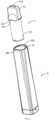
- the embodiments of the present disclosure provide an atomizing apparatus 1, which is configured to combine with a power supply apparatus 2 to form an atomizing device.
- the atomizing device is configured to atomize to-be-atomized solution stored therein into an atomized state, so that users can use, take, or inhale conveniently.
- the to-be-atomized solution may be water, aromatic liquid, mosquito repellent liquid, liquid medicine, electronic cigarette liquids, and the like.
- the atomizing device may be an oral humidor, an aromatherapy device, a mosquito repellent, a medicinal atomizer, an electronic cigarette, and the like.
- the power supply apparatus 2 is electrically connected to the atomizing apparatus 1 to power the atomizing apparatus 1 and make the atomizing device be portable.
- a heating wire and an atomizing chamber for storing the to-be-atomized solution are disposed in the atomizing apparatus 1.
- the to-be-atomized solution includes but is not limited to e-cigarette liquids with different flavors and medical liquids with different therapeutic effects. Since the atomizing apparatus 1 is detachably mounted on the power supply apparatus 2, users can replace the atomizing apparatus 1 or the to-be-atomized solution to meet different use requirements.
- the atomizing apparatus 1 of the embodiments includes: an atomizing housing 11 and an atomizing assembly 14.
- the atomizing housing 11 is defined with a vapor outlet 110 communicating with the interior of the atomizing housing 11. It can be understood that, the atomizing housing 11 is configured to protect the atomizing assembly 14, and is defined with the vapor outlet 110 for discharging vapor.
- the atomizing housing 11 is of a hollow structure, which facilitates to place the atomizing assembly 14 therein.
- the atomizing assembly 14 is disposed inside the atomizing housing 11, and is configured to output vapor. It can be understood that the atomizing assembly 14 is configured to atomize the to-be-atomized solution placed therein into vapor, and output the vapor to the vapor outlet 110.
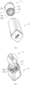
- the atomizing housing 11 is provided with a docking post 12 configured to be inserted into a docking slot 21 of the power supply apparatus 2, and a guiding structure 13 arranged on a side surface of the docking post 12 along a circumferential direction of the docking post 12.
- the guiding structure 13 includes a guiding curved surface 131.
- the guiding curved surface 131 is projecting or concave inward in an axial direction of the docking post 12 with respect to the power supply apparatus 2.
- the atomizing assembly 14 is provided with an atomizing electrical contact 121, which is configured to abut against a power supply electrical contact 211 of the power supply apparatus 2.
- the atomizing electrical contact 121 is exposed out of a bottom surface of the docking post 12 facing away from the vapor outlet 110. It can be understood that the atomizing housing 11 is provided with the docking post 12 and the guiding structure 13.
- the docking post 12 is configured to be inserted into the docking slot 21 of the power supply apparatus 2, and the guiding structure 13 is configured to adjust a relative angle between the docking post 12 and the docking slot 21, allowing the atomizing electrical contact 121 to directly face and abut against the power supply electrical contact 211.
- the docking post 12 has a post structure, and is in clearance fit with the docking slot 21, so that the docking post 12 can rotate around an axis after it is inserted into the docking slot 21, thereby enabling adjustment of the relative angle between the docking post 12 and the docking slot 21.
- the guiding structure 13 is provided with the guiding curved surface 131, and the power supply apparatus 2 is provided with a mating curved surface 201 for fitting with the guiding curved surface 131.
- the mating curved surface 201 can guide the guiding curved surface 131 to move. Specifically, under the action of gravity, the inclined guiding curved surface 131 slips and rotates, until the guiding curved surface 131 is completely in concave-convex fit with the mating curved surface 201. In this case, the relative angle between the docking post 12 and the docking slot 21 is adjusted, allowing the atomizing electrical contact 121 to directly face and abut against the power supply electrical contact 211. In this way, the guiding curved surface 131 can correct the relative angle between the atomizing apparatus 1 and the power supply apparatus 2, thereby realizing the electrical connection between the atomizing apparatus 1 and the power supply apparatus 2.
- the power supply electrical contact 211 and the atomizing electrical contact 121 include but are not limited to conductive pins or conductive sheets.
- the conductive pins may be elastic.
- both the atomizing apparatus 1 and the power supply apparatus 2 are fixedly connected by way of an interference fit, thereby realizing relative fixation of the atomizing apparatus 1 and the power supply apparatus 2.
- the assembly principle of the atomizing apparatus 1 and the power supply apparatus 2 is as follows:
- the user who holds the power supply apparatus 2 in one hand and the atomizing apparatus 1 in the other hand, inserts the docking post 12 into the docking slot 21.
- the atomizing apparatus 1 is located above the power supply apparatus 2, and the atomizing apparatus 1 is guided under gravity to move along a depth direction of the docking slot 21.
- the guiding curved surface 131 interacts with the mating curved surface 201 to adjust the relative angle between the atomizing apparatus 1 and the power supply apparatus 2.
- the atomizing electrical contact 121 and the power supply electrical contact 211 are squarely facing each other and abutting against each other, achieving the electrical connection between the atomizing apparatus 1 and the power supply apparatus 2.
- the user may manually press and rotate the atomizing apparatus 1.
- a complete mating between the atomizing apparatus 1 and the power supply apparatus 2 can be achieved by only rotating the atomizing apparatus 1 less than half a turn.
- the atomizing apparatus 1 is defined with the guiding structure 13, and the guiding structure 13 is provided with the guiding curved surface 131 capable of guiding the atomizing apparatus 1 to rotate with respect to the power supply apparatus 2, so that the atomizing apparatus 1 can be aligned with the power supply apparatus 2 under its own gravity or a pressure provided by a user to realize the electrical connection therebetween.
- the atomizing apparatus 1 can be aligned with the power supply apparatus 2 under its own gravity or a pressure provided by a user to realize the electrical connection therebetween.
- the guiding structure 13 is arranged on the side surface of the docking post 12 and is exposed out of the docking slot 21, so that the user can clearly observe whether the guiding curved surface 131 is in complete fitting with the mating curved surface 201 without multiple times of rotation and adjustment. This improves the user experience.
- the atomizing electrical contact 121 is exposed out of the bottom surface of the docking post 12, so that the atomizing electrical contact 121 can always rotate in the same plane, which facilitates the connection of the atomizing electrical contact 121 and the power supply electrical contact 211.
- At least two guiding structures 13 are symmetrically arranged on the docking post 12.
- a plurality of guiding structures 13 are uniformly arranged on the docking post 12 along the circumferential direction of the docking post 12.
- the guiding structures 13 are defined with the guiding curved surfaces 131, that is, the guiding curved surfaces 131 are symmetrically arranged on the docking post 12, or are uniformly arranged on the docking post 12 along the axial direction of the docking post 12. It can be understood that, correspondingly, the power supply apparatus 2 is defined with mating curved surfaces 201 that are in one-to-one correspondence with the guiding curved surfaces 131.
- the user can insert the docking post 12 into the docking slot 21 at any relative angle, and the guiding curved surfaces 131 can be guided on the corresponding mating curved surfaces 201. Even if there is a slight misalignment between the docking post 12 and the docking slot 21, the misalignment can be adjusted in time.
- the atomizing apparatus 1 further includes a magnetic component 3, which is configured to adhere to a magnetic mating component 4 of the power supply apparatus 2, and drive the guiding structures 13 to align with the power supply apparatus 2.
- the magnetic component 3 is disposed on the bottom surface of the docking post 12 or the side surface of the docking post 12.
- the bottom surface of the docking post 12 is defined with an opening for exposing the atomizing assembly 14, and the magnetic component 3 is disposed on the atomizing assembly 14.
- the magnetic component 3 is configured to mate with the magnetic mating component 4 disposed on a bottom or a wall of the docking slot 21. Specifically, in case the magnetic component 3 is disposed on the bottom surface of the docking post 12 or the bottom surface of the atomizing assembly 14, the magnetic mating component 4 is disposed on the bottom of the docking slot 21.
- the atomizing apparatus 1 is docked with the power supply apparatus 2, that is, when the docking post 12 is inserted into the docking slot 21, the magnetic mating component 4 adheres to the magnetic component 3 to drive the docking post 12 to move along the depth direction of the docking slot 21.
- the magnetic component 3 is disposed on the side surface of the docking post 12
- the magnetic mating component 4 is disposed on the wall of the docking slot 21.
- the magnetic cooperation between the magnetic component 3 and the magnetic mating component 4 cannot guide the docking post 12 to move along the depth direction of the docking slot 21, but can assist in positioning the docking post 12 and the docking slot 21 at a relative angle.
- the magnetic component 3 can guide or assist in adjusting the relative angle between the atomizing apparatus 1 and the power supply apparatus 2, thereby improving the user experience.
- At least two magnetic components 3 are symmetrically arranged on the docking post 12 or the atomizing assembly 14.
- a plurality of magnetic components 3 are uniformly arranged on the docking post 12 or the atomizing assembly 14 along the circumferential direction. It can be understood that the relative position of the magnetic components 3 with respect to the atomizing electrical contact 121 is fixed, and the relative position of the magnetic mating components 4 with respect to the power supply electrical contact 211 is fixed. In this way, in case the magnetic component 3 and the magnetic mating component 4 attract each other and directly faces each other, the atomizing electrical contact 121 directly faces and abuts against the power supply electrical contact.
- the user can insert the docking post 12 into the docking slot 21 at any relative angle, and the magnetic component 3 can fit well with the magnetic mating component 4. Even if there is a slight misalignment between the docking post 12 and the docking slot 21, the misalignment can be adjusted in time.
- the guiding curved surface 131 is a guiding cambered surface, and an arc length of an outer contour line of the guiding arc surface corresponds to a central angel of 45° to 90°.
- the arc length of the outer contour line of the guiding arc surface corresponds to a central angel of 50°, 60° or 70°.
- a height of the docking post 12 is 25 mm to 35 mm.
- the height of the docking post 12 is 25 mm to 35 mm.
- the height of the docking post 12 is 28 mm, 30 mm, or 32 mm.
- the docking post 12 with the above height is convenient for users to hold, and is conducive to the insertion/removal of the docking post 12 into/from the docking slot 21.
- a diameter of the docking post 12 ranges from 10 mm to 20 mm.
- the diameter of the docking post 12 ranges from 13 mm to 15 mm.
- the diameter of the docking post 12 is 12 mm, 14 mm, 16 mm, or 18 mm.
- the docking post 12 can define a suitable atomizing chamber, which is conducive to providing suitable vapor, and is also conducive to the insertion/removal of the docking post 12 into/from the docking slot 21.
- an atomizing device which includes a power supply apparatus 2 and the foregoing atomizing apparatus 1.
- the power supply apparatus 2 includes a power supply housing 22 and a power supply member 23 disposed inside the power supply housing 22.
- the top of the power supply housing 22 is defined with the docking slot 21 configured to receive the docking post 12.
- the power supply member 23 is provided with the power supply electrical contact 211.
- the power supply electrical contact 211 is exposed out of the docking slot 21.
- the mating curved surface 201 for mating with the guiding curved surface 131 is defined at the top of the power supply housing 22.
- the mating curved surface 201 adapts to the shape of the guiding curved surface 131.
- the mating curved surface 201 is an inward concave curved surface; and in case the guiding convex surface is concave toward the power supply apparatus 2, the mating curved surface 201 is a convex curved surface.
- the embodiment based on the arrangement of the atomizing apparatus 1, the embodiment also has the advantages of easy operation and good user experience.
- a side wall of the docking slot 21 is inclined, and the docking post 12 has a wedge-shaped structure fitting with the docking slot 21.
- the docking post 12 fits the docking slot 21, so that the docking post 12 can be tightly fitted with the docking slot 21 after being completely inserted into the docking slot 21, thereby achieving sealing therebetween. This avoids external gases from entering into the interior of the atomizing device, which may further prevent the gas sensor from sensing failure.
- the magnetic mating component 4 mating with the magnetic component 3 is disposed on the bottom or the wall of the docking slot 21.
- the magnetic mating component 4 is disposed on the bottom of the docking slot 21.
- the magnetic mating component 4 adheres to the magnetic component 3 to drive the docking post 12 to move along the depth direction of the docking slot 21. In this way, a complete fitting between the guiding curved surface 131 and the mating curved surface 201 can be achieved without any other external force, thereby allowing the atomizing apparatus 1 and the power supply apparatus 2 to adjust to an appropriate angle.
- the magnetic mating component 4 is disposed on the wall of the docking slot 21.
- the magnetic cooperation between the magnetic component 3 and the magnetic mating component 4 cannot guide the docking post 12 to move along the depth direction of the docking slot 21, but can assist in positioning the docking post 12 and the docking slot 21 at a relative angle.
- the magnetic mating component 4 can be mated with the magnetic component 3, so that the atomizing apparatus 1 can be guided or assisted to adjust the angle relative to the power supply apparatus 2, thereby improving the user experience.
- a guiding convex part 212 is provided on either one of the bottom of the docking slot 21 and the docking end of the docking post 12 docking with the docking slot 21, and a guiding concave part 122 is provided on the other one of the bottom of the docking slot 21 and the docking end of the docking post 12 docking with the docking slot 21.
- the guiding convex part 212 abuts against the guiding concave part 122, to allow the docking post 12 to sealingly abut against the docking slot 21.
- the bottom of the power supply apparatus 2 is provided with a gas sensor electrically connected to the atomizing assembly 14.
- the gas sensor When a user inhales at the vapor outlet 110, the gas sensor may be triggered, which further triggers the atomizing assembly 14 to produce the vapor.
- the sealed state needs to be maintained between the docking post 12 and the docking slot 21, to ensure that the gas sensor is triggered in time, thereby improving the reliability of the gas sensor.
Landscapes
- Special Spraying Apparatus (AREA)
- Electrostatic Spraying Apparatus (AREA)
Priority Applications (1)
| Application Number | Priority Date | Filing Date | Title |
|---|---|---|---|
| RS20250401A RS66761B1 (sr) | 2022-08-31 | 2023-08-01 | Aparat za atomizaciju i uređaj za atomizaciju |
Applications Claiming Priority (1)
| Application Number | Priority Date | Filing Date | Title |
|---|---|---|---|
| CN202222319425.1U CN218389781U (zh) | 2022-08-31 | 2022-08-31 | 雾化装置及雾化设备 |
Publications (2)
| Publication Number | Publication Date |
|---|---|
| EP4331406A1 EP4331406A1 (en) | 2024-03-06 |
| EP4331406B1 true EP4331406B1 (en) | 2025-03-26 |
Family
ID=85030479
Family Applications (1)
| Application Number | Title | Priority Date | Filing Date |
|---|---|---|---|
| EP23188959.3A Active EP4331406B1 (en) | 2022-08-31 | 2023-08-01 | Atomizing apparatus and atomizing device |
Country Status (4)
| Country | Link |
|---|---|
| EP (1) | EP4331406B1 (pl) |
| CN (1) | CN218389781U (pl) |
| PL (1) | PL4331406T3 (pl) |
| RS (1) | RS66761B1 (pl) |
Family Cites Families (3)
| Publication number | Priority date | Publication date | Assignee | Title |
|---|---|---|---|---|
| CN203378561U (zh) * | 2013-07-31 | 2014-01-08 | 刘秋明 | 电子烟 |
| CN115413243B (zh) * | 2019-12-23 | 2024-08-27 | Pax实验室公司 | 蒸发器料盒 |
| CN114668180A (zh) * | 2022-03-08 | 2022-06-28 | 立讯精密工业股份有限公司 | 电子雾化加热储油组件以及电子雾化加热装置 |
-
2022
- 2022-08-31 CN CN202222319425.1U patent/CN218389781U/zh active Active
-
2023
- 2023-08-01 EP EP23188959.3A patent/EP4331406B1/en active Active
- 2023-08-01 PL PL23188959.3T patent/PL4331406T3/pl unknown
- 2023-08-01 RS RS20250401A patent/RS66761B1/sr unknown
Also Published As
| Publication number | Publication date |
|---|---|
| RS66761B1 (sr) | 2025-05-30 |
| CN218389781U (zh) | 2023-01-31 |
| EP4331406A1 (en) | 2024-03-06 |
| PL4331406T3 (pl) | 2025-04-28 |
Similar Documents
| Publication | Publication Date | Title |
|---|---|---|
| CN106102808B (zh) | 吸入器和吸入器组 | |
| US11878094B2 (en) | Humidifier tub for CPAP device | |
| WO2021104389A1 (zh) | 雾化组件及电子烟 | |
| EP4331406B1 (en) | Atomizing apparatus and atomizing device | |
| CN220046732U (zh) | 一种小型便携式雾化器 | |
| CN113546255A (zh) | 疫苗雾化装置 | |
| CN223009578U (zh) | 面罩可拆卸式雾化器 | |
| CN222605177U (zh) | 一种呼吸雾化装置及呼吸雾化转接管 | |
| US20220235952A1 (en) | Humidifier | |
| JP3685671B2 (ja) | 吸入式投薬器 | |
| CN116509698A (zh) | 眼部按摩器 | |
| CN214807548U (zh) | 一种空气压缩式医用雾化器 | |
| US20230321364A1 (en) | Electronic vaporization device | |
| CN113456950A (zh) | 一种雾化器 | |
| WO2026026720A1 (zh) | 雾化器、面罩及雾化装置 | |
| CN220236062U (zh) | 一种雾化设备 | |
| CN215351311U (zh) | 一种可持续性湿化使用的管式雾化面罩 | |
| CN213609063U (zh) | 一种口含式便携雾化装置 | |
| EP4458177B1 (en) | Electronic atomisation device and atomiser | |
| CN215938629U (zh) | 方便拆装的雾化器 | |
| CN212439628U (zh) | 雾化器 | |
| CN217609551U (zh) | 电源组件以及气溶胶生成装置 | |
| CN217510956U (zh) | 一种便于连接使用的雾化罐 | |
| CN224113086U (zh) | 一种雾化药杯以及雾化装置 | |
| CN120437440A (zh) | 雾化器 |
Legal Events
| Date | Code | Title | Description |
|---|---|---|---|
| PUAI | Public reference made under article 153(3) epc to a published international application that has entered the european phase |
Free format text: ORIGINAL CODE: 0009012 |
|
| STAA | Information on the status of an ep patent application or granted ep patent |
Free format text: STATUS: REQUEST FOR EXAMINATION WAS MADE |
|
| 17P | Request for examination filed |
Effective date: 20230801 |
|
| AK | Designated contracting states |
Kind code of ref document: A1 Designated state(s): AL AT BE BG CH CY CZ DE DK EE ES FI FR GB GR HR HU IE IS IT LI LT LU LV MC ME MK MT NL NO PL PT RO RS SE SI SK SM TR |
|
| RIC1 | Information provided on ipc code assigned before grant |
Ipc: A24F 40/10 20200101ALN20241113BHEP Ipc: A24F 40/40 20200101AFI20241113BHEP |
|
| GRAP | Despatch of communication of intention to grant a patent |
Free format text: ORIGINAL CODE: EPIDOSNIGR1 |
|
| STAA | Information on the status of an ep patent application or granted ep patent |
Free format text: STATUS: GRANT OF PATENT IS INTENDED |
|
| RIC1 | Information provided on ipc code assigned before grant |
Ipc: A24F 40/10 20200101ALN20241119BHEP Ipc: A24F 40/40 20200101AFI20241119BHEP |
|
| INTG | Intention to grant announced |
Effective date: 20241220 |
|
| GRAS | Grant fee paid |
Free format text: ORIGINAL CODE: EPIDOSNIGR3 |
|
| GRAA | (expected) grant |
Free format text: ORIGINAL CODE: 0009210 |
|
| STAA | Information on the status of an ep patent application or granted ep patent |
Free format text: STATUS: THE PATENT HAS BEEN GRANTED |
|
| AK | Designated contracting states |
Kind code of ref document: B1 Designated state(s): AL AT BE BG CH CY CZ DE DK EE ES FI FR GB GR HR HU IE IS IT LI LT LU LV MC ME MK MT NL NO PL PT RO RS SE SI SK SM TR |
|
| REG | Reference to a national code |
Ref country code: GB Ref legal event code: FG4D |
|
| REG | Reference to a national code |
Ref country code: CH Ref legal event code: EP |
|
| P01 | Opt-out of the competence of the unified patent court (upc) registered |
Free format text: CASE NUMBER: APP_8989/2025 Effective date: 20250221 |
|
| REG | Reference to a national code |
Ref country code: DE Ref legal event code: R096 Ref document number: 602023002574 Country of ref document: DE |
|
| REG | Reference to a national code |
Ref country code: IE Ref legal event code: FG4D |
|
| PG25 | Lapsed in a contracting state [announced via postgrant information from national office to epo] |
Ref country code: FI Free format text: LAPSE BECAUSE OF FAILURE TO SUBMIT A TRANSLATION OF THE DESCRIPTION OR TO PAY THE FEE WITHIN THE PRESCRIBED TIME-LIMIT Effective date: 20250326 |
|
| PGFP | Annual fee paid to national office [announced via postgrant information from national office to epo] |
Ref country code: PL Payment date: 20250609 Year of fee payment: 3 |
|
| REG | Reference to a national code |
Ref country code: LT Ref legal event code: MG9D |
|
| PG25 | Lapsed in a contracting state [announced via postgrant information from national office to epo] |
Ref country code: NO Free format text: LAPSE BECAUSE OF FAILURE TO SUBMIT A TRANSLATION OF THE DESCRIPTION OR TO PAY THE FEE WITHIN THE PRESCRIBED TIME-LIMIT Effective date: 20250626 |
|
| PG25 | Lapsed in a contracting state [announced via postgrant information from national office to epo] |
Ref country code: HR Free format text: LAPSE BECAUSE OF FAILURE TO SUBMIT A TRANSLATION OF THE DESCRIPTION OR TO PAY THE FEE WITHIN THE PRESCRIBED TIME-LIMIT Effective date: 20250326 |
|
| PG25 | Lapsed in a contracting state [announced via postgrant information from national office to epo] |
Ref country code: LV Free format text: LAPSE BECAUSE OF FAILURE TO SUBMIT A TRANSLATION OF THE DESCRIPTION OR TO PAY THE FEE WITHIN THE PRESCRIBED TIME-LIMIT Effective date: 20250326 |
|
| PG25 | Lapsed in a contracting state [announced via postgrant information from national office to epo] |
Ref country code: GR Free format text: LAPSE BECAUSE OF FAILURE TO SUBMIT A TRANSLATION OF THE DESCRIPTION OR TO PAY THE FEE WITHIN THE PRESCRIBED TIME-LIMIT Effective date: 20250627 Ref country code: BG Free format text: LAPSE BECAUSE OF FAILURE TO SUBMIT A TRANSLATION OF THE DESCRIPTION OR TO PAY THE FEE WITHIN THE PRESCRIBED TIME-LIMIT Effective date: 20250326 |
|
| REG | Reference to a national code |
Ref country code: NL Ref legal event code: MP Effective date: 20250326 |
|
| PG25 | Lapsed in a contracting state [announced via postgrant information from national office to epo] |
Ref country code: NL Free format text: LAPSE BECAUSE OF FAILURE TO SUBMIT A TRANSLATION OF THE DESCRIPTION OR TO PAY THE FEE WITHIN THE PRESCRIBED TIME-LIMIT Effective date: 20250326 |
|
| PG25 | Lapsed in a contracting state [announced via postgrant information from national office to epo] |
Ref country code: SE Free format text: LAPSE BECAUSE OF FAILURE TO SUBMIT A TRANSLATION OF THE DESCRIPTION OR TO PAY THE FEE WITHIN THE PRESCRIBED TIME-LIMIT Effective date: 20250326 |
|
| REG | Reference to a national code |
Ref country code: AT Ref legal event code: MK05 Ref document number: 1778135 Country of ref document: AT Kind code of ref document: T Effective date: 20250326 |
|
| PG25 | Lapsed in a contracting state [announced via postgrant information from national office to epo] |
Ref country code: SM Free format text: LAPSE BECAUSE OF FAILURE TO SUBMIT A TRANSLATION OF THE DESCRIPTION OR TO PAY THE FEE WITHIN THE PRESCRIBED TIME-LIMIT Effective date: 20250326 |
|
| PG25 | Lapsed in a contracting state [announced via postgrant information from national office to epo] |
Ref country code: PT Free format text: LAPSE BECAUSE OF FAILURE TO SUBMIT A TRANSLATION OF THE DESCRIPTION OR TO PAY THE FEE WITHIN THE PRESCRIBED TIME-LIMIT Effective date: 20250728 Ref country code: ES Free format text: LAPSE BECAUSE OF FAILURE TO SUBMIT A TRANSLATION OF THE DESCRIPTION OR TO PAY THE FEE WITHIN THE PRESCRIBED TIME-LIMIT Effective date: 20250326 |
|
| PGFP | Annual fee paid to national office [announced via postgrant information from national office to epo] |
Ref country code: DE Payment date: 20250812 Year of fee payment: 3 |
|
| PG25 | Lapsed in a contracting state [announced via postgrant information from national office to epo] |
Ref country code: IT Free format text: LAPSE BECAUSE OF FAILURE TO SUBMIT A TRANSLATION OF THE DESCRIPTION OR TO PAY THE FEE WITHIN THE PRESCRIBED TIME-LIMIT Effective date: 20250326 |
|
| PG25 | Lapsed in a contracting state [announced via postgrant information from national office to epo] |
Ref country code: AT Free format text: LAPSE BECAUSE OF FAILURE TO SUBMIT A TRANSLATION OF THE DESCRIPTION OR TO PAY THE FEE WITHIN THE PRESCRIBED TIME-LIMIT Effective date: 20250326 |
|
| PG25 | Lapsed in a contracting state [announced via postgrant information from national office to epo] |
Ref country code: EE Free format text: LAPSE BECAUSE OF FAILURE TO SUBMIT A TRANSLATION OF THE DESCRIPTION OR TO PAY THE FEE WITHIN THE PRESCRIBED TIME-LIMIT Effective date: 20250326 |
|
| PGFP | Annual fee paid to national office [announced via postgrant information from national office to epo] |
Ref country code: RS Payment date: 20250721 Year of fee payment: 3 |
|
| PG25 | Lapsed in a contracting state [announced via postgrant information from national office to epo] |
Ref country code: RO Free format text: LAPSE BECAUSE OF FAILURE TO SUBMIT A TRANSLATION OF THE DESCRIPTION OR TO PAY THE FEE WITHIN THE PRESCRIBED TIME-LIMIT Effective date: 20250326 |
|
| PG25 | Lapsed in a contracting state [announced via postgrant information from national office to epo] |
Ref country code: SK Free format text: LAPSE BECAUSE OF FAILURE TO SUBMIT A TRANSLATION OF THE DESCRIPTION OR TO PAY THE FEE WITHIN THE PRESCRIBED TIME-LIMIT Effective date: 20250326 |
|
| PG25 | Lapsed in a contracting state [announced via postgrant information from national office to epo] |
Ref country code: IS Free format text: LAPSE BECAUSE OF FAILURE TO SUBMIT A TRANSLATION OF THE DESCRIPTION OR TO PAY THE FEE WITHIN THE PRESCRIBED TIME-LIMIT Effective date: 20250726 |
|
| REG | Reference to a national code |
Ref country code: DE Ref legal event code: R097 Ref document number: 602023002574 Country of ref document: DE |
|
| PG25 | Lapsed in a contracting state [announced via postgrant information from national office to epo] |
Ref country code: DK Free format text: LAPSE BECAUSE OF FAILURE TO SUBMIT A TRANSLATION OF THE DESCRIPTION OR TO PAY THE FEE WITHIN THE PRESCRIBED TIME-LIMIT Effective date: 20250326 |
|
| PG25 | Lapsed in a contracting state [announced via postgrant information from national office to epo] |
Ref country code: CZ Free format text: LAPSE BECAUSE OF FAILURE TO SUBMIT A TRANSLATION OF THE DESCRIPTION OR TO PAY THE FEE WITHIN THE PRESCRIBED TIME-LIMIT Effective date: 20250326 |
|
| PGFP | Annual fee paid to national office [announced via postgrant information from national office to epo] |
Ref country code: CY Payment date: 20250610 Year of fee payment: 3 |
|
| PLBE | No opposition filed within time limit |
Free format text: ORIGINAL CODE: 0009261 |
|
| STAA | Information on the status of an ep patent application or granted ep patent |
Free format text: STATUS: NO OPPOSITION FILED WITHIN TIME LIMIT |
|
| REG | Reference to a national code |
Ref country code: CH Ref legal event code: L10 Free format text: ST27 STATUS EVENT CODE: U-0-0-L10-L00 (AS PROVIDED BY THE NATIONAL OFFICE) Effective date: 20260211 |
|
| 26N | No opposition filed |
Effective date: 20260105 |
|
| PG25 | Lapsed in a contracting state [announced via postgrant information from national office to epo] |
Ref country code: MC Free format text: LAPSE BECAUSE OF FAILURE TO SUBMIT A TRANSLATION OF THE DESCRIPTION OR TO PAY THE FEE WITHIN THE PRESCRIBED TIME-LIMIT Effective date: 20250326 |
|
| PG25 | Lapsed in a contracting state [announced via postgrant information from national office to epo] |
Ref country code: LU Free format text: LAPSE BECAUSE OF NON-PAYMENT OF DUE FEES Effective date: 20250801 |