EP4331348B1 - Modulares wandsystem und modulare wand - Google Patents
Modulares wandsystem und modulare wand Download PDFInfo
- Publication number
- EP4331348B1 EP4331348B1 EP22193649.5A EP22193649A EP4331348B1 EP 4331348 B1 EP4331348 B1 EP 4331348B1 EP 22193649 A EP22193649 A EP 22193649A EP 4331348 B1 EP4331348 B1 EP 4331348B1
- Authority
- EP
- European Patent Office
- Prior art keywords
- plant
- board
- bedding material
- wall panel
- elongated
- Prior art date
- Legal status (The legal status is an assumption and is not a legal conclusion. Google has not performed a legal analysis and makes no representation as to the accuracy of the status listed.)
- Active
Links
Images


Classifications
-
- A—HUMAN NECESSITIES
- A01—AGRICULTURE; FORESTRY; ANIMAL HUSBANDRY; HUNTING; TRAPPING; FISHING
- A01G—HORTICULTURE; CULTIVATION OF VEGETABLES, FLOWERS, RICE, FRUIT, VINES, HOPS OR SEAWEED; FORESTRY; WATERING
- A01G9/00—Cultivation in receptacles, forcing-frames or greenhouses; Edging for beds, lawn or the like
- A01G9/02—Receptacles, e.g. flower-pots or boxes; Glasses for cultivating flowers
- A01G9/022—Pots for vertical horticulture
- A01G9/025—Containers and elements for greening walls
-
- E—FIXED CONSTRUCTIONS
- E01—CONSTRUCTION OF ROADS, RAILWAYS, OR BRIDGES
- E01F—ADDITIONAL WORK, SUCH AS EQUIPPING ROADS OR THE CONSTRUCTION OF PLATFORMS, HELICOPTER LANDING STAGES, SIGNS, SNOW FENCES, OR THE LIKE
- E01F8/00—Arrangements for absorbing or reflecting air-transmitted noise from road or railway traffic
- E01F8/0005—Arrangements for absorbing or reflecting air-transmitted noise from road or railway traffic used in a wall type arrangement
- E01F8/0011—Plank-like elements
-
- E—FIXED CONSTRUCTIONS
- E01—CONSTRUCTION OF ROADS, RAILWAYS, OR BRIDGES
- E01F—ADDITIONAL WORK, SUCH AS EQUIPPING ROADS OR THE CONSTRUCTION OF PLATFORMS, HELICOPTER LANDING STAGES, SIGNS, SNOW FENCES, OR THE LIKE
- E01F8/00—Arrangements for absorbing or reflecting air-transmitted noise from road or railway traffic
- E01F8/02—Arrangements for absorbing or reflecting air-transmitted noise from road or railway traffic specially adapted for sustaining vegetation or for accommodating plants ; Embankment-type or crib-type noise barriers; Retaining walls specially adapted to absorb or reflect noise
- E01F8/021—Arrangements for absorbing or reflecting air-transmitted noise from road or railway traffic specially adapted for sustaining vegetation or for accommodating plants ; Embankment-type or crib-type noise barriers; Retaining walls specially adapted to absorb or reflect noise with integral support structure
-
- E—FIXED CONSTRUCTIONS
- E04—BUILDING
- E04C—STRUCTURAL ELEMENTS; BUILDING MATERIALS
- E04C1/00—Building elements of block or other shape for the construction of parts of buildings
- E04C1/39—Building elements of block or other shape for the construction of parts of buildings characterised by special adaptations, e.g. serving for locating conduits, for forming soffits, cornices, or shelves, for fixing wall-plates or door-frames, for claustra
- E04C1/395—Building elements of block or other shape for the construction of parts of buildings characterised by special adaptations, e.g. serving for locating conduits, for forming soffits, cornices, or shelves, for fixing wall-plates or door-frames, for claustra for claustra, fences, planting walls, e.g. sound-absorbing
-
- E—FIXED CONSTRUCTIONS
- E04—BUILDING
- E04B—GENERAL BUILDING CONSTRUCTIONS; WALLS, e.g. PARTITIONS; ROOFS; FLOORS; CEILINGS; INSULATION OR OTHER PROTECTION OF BUILDINGS
- E04B2/00—Walls, e.g. partitions, for buildings; Wall construction with regard to insulation; Connections specially adapted to walls
- E04B2/02—Walls, e.g. partitions, for buildings; Wall construction with regard to insulation; Connections specially adapted to walls built-up from layers of building elements
- E04B2002/0202—Details of connections
- E04B2002/0204—Non-undercut connections, e.g. tongue and groove connections
- E04B2002/0208—Non-undercut connections, e.g. tongue and groove connections of trapezoidal shape
-
- Y—GENERAL TAGGING OF NEW TECHNOLOGICAL DEVELOPMENTS; GENERAL TAGGING OF CROSS-SECTIONAL TECHNOLOGIES SPANNING OVER SEVERAL SECTIONS OF THE IPC; TECHNICAL SUBJECTS COVERED BY FORMER USPC CROSS-REFERENCE ART COLLECTIONS [XRACs] AND DIGESTS
- Y02—TECHNOLOGIES OR APPLICATIONS FOR MITIGATION OR ADAPTATION AGAINST CLIMATE CHANGE
- Y02P—CLIMATE CHANGE MITIGATION TECHNOLOGIES IN THE PRODUCTION OR PROCESSING OF GOODS
- Y02P60/00—Technologies relating to agriculture, livestock or agroalimentary industries
- Y02P60/20—Reduction of greenhouse gas [GHG] emissions in agriculture, e.g. CO2
Definitions
- the invention refers to a modular wall system comprising a plurality of elongated wall panels disposed on one another, a plant bedding material tile, a seed/plant cup, a board and an irrigation pipe. Also, a modular wall is provided.
- the present innovation aims to subdue this myriad of noises by natural and sustainable means. Further, the present innovation expands on the art described in US Patent Application 16/805,093 , articulating an acoustic solution to subdue noise in proximity to the modular vertical wall, that can also grow plant material.
- US2011/225883 discloses a vegetation wall for supporting vegetation.
- JP 2011125260A discloses an exterior or interior wall for planting vegetation.
- JP2006280285A discloses a green wall using capillary action.
- US2022039327A discloses an automated outdoor modular vertical plant cultivation system forming a vertical structure.
- An object of the present invention is to provide a modular wall system that at least partly overcome the drawbacks and issues mentioned above.
- a modular wall system comprising a plurality of elongated wall panels disposed on one another, a plant bedding material tile, a seed/plant cup, a board, and an irrigation pipe, wherein:
- a modular wall system is provided that is based on vertically disposed elongated wall panels that are configured to be arranged in a shelf-like manner one on top of the other.
- the elongated panels are configured to support one or more plant bedding material tiles.
- a board is configured to couple to at least one of the flanges of a respective elongated panel to thereby form a wall panel interior.
- the board comprises openings allowing the insertion of seed/plant cups into corresponding openings in the plant bedding material tile.
- the invention provides a living wall that contributes to the reduction of pollutants from the air, reduces the ambient temperature, contributes to the beauty of the urban landscape and, not at least reduces ambient noise.
- the length, and the height of the wall may be easily adapted to actual circumstances.
- the type of plants may be easily exchanged over the seasons if necessary and also the choice of plant bedding material may be adapted to the choice of plants.
- the vertical modular wall system allows the formation of a wall by arranging the vertical wall panels one on top of the other in a shelf-like manner.
- the vertical panels can be single or double sided to retain plant bedding material and/or boards on one side of the wall and/or on both sides.
- the two opposing sides of the resulting wall may be provided with different appearance and different properties.
- the boards may be solid boards or be acoustic boards.
- Each elongated wall panel may comprise a combination of solid boards and acoustic boards, the boards being distributed along the longitudinal extension of the wall panel. Also, not all boards must be provided with holes configured to receive seed/plant cups.
- sound attenuating material can be coupled to the interior vertical wall of the elongated wall panel and/or to the interior face of the solid or acoustic board that encloses the wall panel interior from the exterior.
- the plant bedding material and/or the sound attenuating material is disposed between the vertical wall panel and the solid/acoustic board, wherein the top and bottom flanges of the elongated wall panel couple to the solid/acoustic board to form an enclosure.
- the fluid can drip from above onto the plant bedding material tile below. This is allowed in the event the irrigation pipe is arranged along either a top or bottom surface of the top flange of the respective elongated wall panel. One or both of the top and bottom flanges may be provided with weep holes.
- the fluid can irrigate the plant bedding material tile from below. In such event, the irrigation pipe may be arranged along e.g. the bottom flange of the respective elongated wall panel.
- Openings in the plant bedding material tile and the solid/acoustic boards enable seeds/plant cups to be inserted from the exterior surface of the solid/acoustic board into said pre-fabricated opening/s. Once irrigated, the plant/s' roots grow into the bedding material, thereby anchoring the plant/s.
- the board may in one embodiment be an acoustic board.
- the board may in alternative embodiment be a non-acoustic board.
- the board no matter if it is solid or acoustic, may have at least one sound attenuation through opening. At least one of: the size, the quantity, the form, the thickness, and/or the location of the openings in the sound attenuation may be configured to attenuate sound level intensity and/or frequency by local ambient conditions. At least one of the plant bedding material tile and the seed/plant cup may exhibit sound attenuation properties.
- the board may comprise a bore configured to couple the board to the elongated wall panel by means of a mechanical fastener.
- the mechanical fastener may by way of example be a screw or a clip.
- the board may be removably fixated between the top and bottom flanges of the elongated wall panel.
- the board may be openable by a tilting movement while being supported by one of the top and bottom flanges.
- the modular wall system may comprise at least two single-sided or double-sided elongated wall panels.
- a flange of a first elongated wall panel may be configured to be coupled to a flange of a second elongated wall panel by at least one reciprocating mechanical key.
- the reciprocating mechanical key may be formed as an undulating pattern having an extension in parallel with the elongated extension of the wall panel.
- the undulating pattern of the mechanical key of the top flange of a first elongated wall panel may be complementary to the undulating pattern of the mechanical key of the bottom flange of a second elongated wall panel.
- the top and bottom flanges of the elongated wall panels may comprise weep holes.
- the number of weep holes and also their positions may correspond to the number and positions of cup bedding material openings of the plant bedding material tiles. Thereby, each seed/plant may be properly irrigated.
- the plant bedding material tile may comprise at least one funnel.
- the at least one funnel may be substantially vertically aligned with a respective cup bedding material opening in the plant bedding material tile.
- the number of funnels and their positions may correspond to the cup bedding material openings of the plant bedding material tile.
- the plant bedding material tile may be configured to be coupled to the board and/or to a plant bedding material casing.
- the casing may be seen as a protection that facilitates handling of the tile and also that prevents the tile from disintegrating and crumbling over time.
- the invention relates to a modular wall formed by the use of a modular wall system with the features according to any of claims 1-10, wherein a plurality of elongated wall panels are arranged in stacked relationship, one on top of the other, between at least two vertically extending posts.
- the modular wall may be formed by at least two single-sided or double-sided elongated wall panels and at least one of the sides of the modular wall may comprise a plurality of seed/plant cups.
- a modular wall system comprises a plurality of elongated wall panels disposed on one another, a plant bedding material tile, a seed/plant cup, and an acoustic board; wherein
- the modular wall system of this alternative aspect has a similar overall design as the system described above. Hence, the features and advantages discussed above are equally applicable to this embodiment.
- At least one of: the size, the quantity, the form, the thickness, and/or the location of openings in the acoustic board may be configured to attenuate sound level intensity and/or frequency by local ambient conditions.
- the acoustic board may comprise a bore configured to couple the acoustic board to the elongated wall panel by means of a mechanical fastener.
- the acoustic board may be configured to be removable fixated between the top and bottom flanges of the elongated wall panel.
- the acoustic board may be openable by a tilting movement while being supported by one of the top and bottom flanges.
- the modular wall system may comprise at least two single-sided or double-sided elongated wall panels.
- a flange of a first elongated wall panel may be configured to be coupled to a flange of a second elongated wall panel by at least one reciprocating mechanical key.
- the plant bedding material tile may be configured to be coupled to the acoustic board and/or to a plant bedding material casing.
- a modular wall system comprising a plurality of elongated wall panels disposed on one another.
- the modular wall system comprises a sound attenuation material tile and an acoustic board; and wherein:
- the modular wall system of this additional alternative aspect has a similar overall design as the system described above. Hence, the features and advantages discussed above are equally applicable to this embodiment.
- the acoustic board may comprise at least one opening for a seed/plant cup.
- the sound attenuation material tile can couple to at least one seed/plant cup.
- the acoustic board can couple to a sound attenuation material tile.
- the sound attenuation material tile may be a plant bedding material tile and the acoustic board can couple to a plant bedding material casing encircling the sound attenuation material tile. At least one of: the size, the quantity, the form, the thickness, and/or the location of the openings in the sound attenuation tile may be configured to attenuate sound level intensity and/or frequency by local ambient conditions.
- the acoustic board may be configured to be detachable and secured to the elongated wall panel by a mechanical fastener.
- the acoustic board may be configured to be removably fixed between the top and bottom flanges of the elongated wall panel.
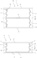
- FIG. 1a and 1b show single- and double-sided wall panel 9, 10 sections, respectively.
- Fig. 1a shows a transverse section of a "C" shaped single-sided elongated wall panel 9.
- the elongated wall panel 9 comprises a vertical wall 4, a top flange 2 and a bottom flange 3.
- the flanges 2, 3 show mechanical keys 5.
- the mechanical keys 5 are disclosed as having an undulated pattern.
- the reciprocating mechanical key, no matter pattern may have an extension in parallel with the elongated extension of the wall panel.
- the undulating pattern of the top flange 2 of a first elongated wall panel may be complementary to the undulating pattern of the mechanical key of the bottom flange 3 of a second elongated wall panel. It is to be understood that other types of mechanical keys may be equally applied.
- the mechanical keys 5 are configured to interlock with elongated wall panels 9, placed above and/or below a first wall panel 9. Accordingly, the top flange 2 of a first lower elongated wall panel 9 is configured to lockingly engage the bottom flange 3 of a second upper elongated wall panel 9. Thus, a plurality of elongated wall panels 9 are configured to be vertically stacked, one on top of the other.
- the present figure's single-sided cross-section can be configured to retain plant material and/or a board on one side of the single-sided wall panel 9.
- top and bottom flanges 2, 3 do both comprise through-going weep holes 41.
- the weep holes will be further discussed below.
- a transverse section of a double-sided elongated wall panel 10 is shown.
- the elongated wall panel 10 has an overall "I" shaped cross-section.
- the elongated wall panel 10 comprises a vertical wall 4, a top flange 2 and a bottom flange 3.
- the flanges 2, 3 show mechanical keys 5.
- the mechanical keys 5 are disclosed as having an undulated pattern.
- the undulating pattern of the top flange 2 of a first elongated wall panel may be complementary to the undulating pattern of the mechanical key of the bottom flange 3 of a second elongated wall panel. It is to be understood that other types of mechanical keys may be equally applied.
- the mechanical keys 5 are configured to interlock with elongated wall panels 10, placed above and/or below a first wall panel 10. Accordingly, the top flange 2 of a first lower elongated wall panel 10 is configured to lockingly engage the bottom flange 3 of a second upper elongated wall panel 10. Thus, a plurality of elongated wall panels 10 are configured to be vertically stacked, one on top of the other.
- top and bottom flanges 2, 3 do both comprise through-going weep holes 41.
- the weep holes will be further discussed below.
- one or both of the flanges 2, 3 is formed or adapted to retain a means of conveying fluid and/or electricity. This will be further explained below.
- one or both of the flanges 2, 3 is configured to retain a solid or acoustic board (omitted in Figs. 1a and 1b ) and/or to have a means to fasten a solid/acoustic board to one or both of the flanges 2, 3. This will be further discussed below.
- the elongated wall panel 9, 10 is a single- or double-sided panel
- the elongated wall panel 9, 10 is an elongated structure configured to distribute its weight laterally along its bottom flange 3 surface.
- An arrangement of wall panels 1, with two or more elongated wall panels 9, 10 arranged above one another, is configured to be secured to or supported by at least two vertical posts 8 disposed at the opposite ends of the elongated wall panels 9, 10.
- the posts 8 are only illustrated highly schematically.
- the elongated wall panels 9, 10 can be fabricated by methods of: pultrusion, extrusion, 3D printing, and pressure forming.
- the elongated wall panels 9, 10 can be made of metallic or non-metallic material that can be noncorrosive and inert to the elements where it is placed.
- the present figure's cross-section can be configured to retain plant material and/or plant material and boards on one or both sides of the double-sided wall panel 10.
- one side may be configured to retain plant material whereas the other side may be configured to retain a board.
- one and the same side may be configured to retain a combination of boards and plant material.
- the board may be of an acoustic or non-acoustic material.
- a modular wall 100 according to the invention can be comprised of two single-sided wall panels 9 disposed back-to-back to one another with an air gap 11 between them, or with a barrier member 12.
- the barrier member 12 can have several a single or multiple uses further described in more detail herein.
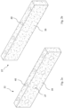
- FIGs. 2a and 2b show front and back perspective views of a plant bedding material tile 22, respectively.
- Fig. 2a shows in perspective view a plant bedding material tile 22.
- the plant bedding material tile 22 can be fabricated of organic material that can be comprised of coconut fiber, wood chips, pulverized tree bark, and/or similar material. In other embodiments, the plant bedding material tile 22 can also be comprised of manufactured fiber such as mineral wool or rock wool.
- the plant bedding material tile 22 is configured to provide an anchoring medium for plants' roots. In addition, the plant bedding material tile 22 can retain and provide humidity, minerals and additives for the plants.
- the plant bedding material tile 22 can be formed in a mold under pressure.
- the plant bedding material tile 22 can have varying thicknesses and profiles.
- the plant bedding material aggregate can be mixed with a binder.
- the binder material can be produced by nature, having no harmful environmental impact.
- at least one plant bedding material tile 22 can be pre-seeded.
- the plant bedding material tile 22 is formed with at least one cup bedding material opening 27 configured for a seed/plant cup (see Fig. 5b ).
- the at least one cup bedding material opening 27 is arranged in one of two opposing vertical side walls of the plant bedding material tile 22.
- the opening 27 does preferably have a non-horizontal extension.
- the cup as will be discussed below, is configured to be inserted through a casing and/or a board which as such may be solid/acoustic.
- the plant bedding material tile 22 can be placed in a fabric casing 30, as shown in Figs. 3a and 3b .
- the present figure shows a funnel 40 on the top wall of the plant bedding material tile 22.
- the funnel 40 can be at least partially formed as a recess in the bedding material tile 22 and/or be a separate member to be inserted upon installation of the plant bedding material tile 22.
- the plant bedding material tile 22 is configured to be positioned below an irrigation pipe as will be further discussed below with reference to Fig. 5b . Irrigation fluid can then flow by gravity and/or under pressure to the plant bedding material tile 22 disposed below.
- the irrigation fluid is preferably configured to be supplied from the irrigation pipe to the one or more funnels 40 in the plant bedding material tile 22 in a manner to be described below.
- Fig. 2b shows a back side perspective view of the plant bedding material tile 22.
- the back side of the plant bedding material tile 22 is configured to face an inner portion of the vertical wall panel 4 of an elongated wall panel 9, 10.
- the back side of the plant bedding material tile 22 surface is solid, i.e. without any cup-receiving openings.
- the plant bedding material tile 22 can be configured to couple to the vertical wall panel 4 of the elongated wall panel 9, 10 and/or to a solid/acoustic board 6, 7 that couples to at least one flange 2, 3 of the wall panel 9, 10.
- the board 6, 7 will be further discussed below with reference to Figs. 4a and 4b .
- the plant bedding material tile 22 has sound attenuation properties that can vary by at least one of: the material thickness, density, material, and moisture absorbance capability.
- sound attenuation material 39 can be used in lieu of plant bedding material tile 22 of similar or better sound attenuation properties.
- the principle as is disclosed in Figs. 2a, 2b is equally applicable in the event the tile instead of being made of a plant bedding material is made of sound attenuating material to thereby constitute a sound attenuating tile.
- any cup bedding material openings 27 and funnels 40 may be omitted.
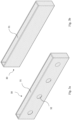
- FIGs. 3a and 3b show front and back perspective views of a plant bedding material casing 30, respectively.
- Fig. 3a shows a perspective view of the plant bedding material casing 30.
- the casing 30 form substantially emulates the plant bedding material tile 22 form.
- the plant bedding material tile 22 is configured to be disposed inside the casing 30.
- the casing's 30 prime purpose is to keep the tile 22 form intact and to prevent the tile's 22 organic material from crumbling once the tile 22 comes in contact with fluid 20.
- the tile 22 material expands upon coming into contact with fluid 20.
- the casing 30 limits the rate of expansion while maintaining the tile's 22 form
- the casing 30 provides is a good contact surface for coupling the plant bedding material tile 22 to the vertical wall 4 of the elongated wall panel 9, 10 and/or to an interior surface of the solid or acoustic board 6, 7 (not shown) coupled to at least one of the top and bottom flanges 2, 3. Further, the plant bedding material tile 22 can be encased inside a casing 30 and the casing 30 can then couple to the vertical portion of the vertical wall 4 and/or the solid/acoustic board 6, 7.
- the present figure shows a top surface opening 31 for the insertion of a plant bedding material tile 22.
- this surface 31 can be fully or partially enclosed following the insertion of the plant bedding material tile 22.
- On the exterior facing side of the casing 30, four plant cup openings 32 are shown configured to receive seed/plant cups 25 through the casing 30 into the plant's bedding material tile 22.
- the casing 30 can be made of non-organic or organic material fabric such as hemp or canvas, with a weave pattern that reduces irrigation fluid 20 egress. In addition, at least a portion of the casing 30 can be treated to become partially or fully non-permeable.
- Fig. 3b shows the back side of the plant bedding material tile casing 30.
- the back side of the plant bedding material tile casing 30 is configured to face the inner vertical wall of the wall panel 4 of the elongated wall panel 9, 10.
- the back side of the casing 30 can in at least one embodiment be figured to couple to the vertical wall 4 of an elongated wall panel 9, 10.
- the bedding material casing 30 may be omitted, depending on the physical properties/inherent strength of the plant bedding material tile 22.
- the bedding material tile 22 can be configured to couple directly to the vertical wall 4 of the elongated wall panel 9, 10 and/or to the inner face of a board 6, 7 similarly to mounting the casing 30 as shown in Figs. 6a and 6b .
- tile instead should be operable as a sound attenuation tile, such tile may be configured to be disposed inside the casing 30. It is realized that the plant cup openings 32 in such case can be omitted.
- FIGs. 4a and 4b show front and back perspective views of an acoustic board 7, respectively.
- the description is equally, unless not explicitly stipulated, applicable to a solid board 6.
- Fig. 4a shows a perspective view of an acoustic board 7.
- the acoustic board 7 is configured to couple to at least one of the top and bottom flanges 2, 3 of a elongated wall panel 9, 10 in a manner that will be discussed below.
- the acoustic board 7 is configured to be disposed on the exterior face of the modular wall 100.
- the acoustic board 7 is configured to help attenuation of ambient noise, to provide a mounting structure for a seed/plant cup 25, to protect the irrigation system and the plant bedding material 26 in the plant bedding material tile 22 from vandals, to protect any electrical devices retained inside an arrangement of wall panels 1 from thieves, and to help aeration of the plant bedding material 26.
- the board's exterior surface can also be configured to receive graphic print. Such print can show pattern and colour in the form of imagery and text.
- the present figure shows three types of openings in the exterior face of the acoustic board: openings 32 for a seed/plant cup; openings 50 that dampens sound; and bore openings 13 for coupling the acoustic board 7 to a support structure.
- the acoustic board 7 is configured to receive at least one seed/plant cup 25 (see e.g. Fig. 5b ) through a respective opening 32.
- the opening 32 is sized to be compatible with a seed/plant cup 25.
- a mechanical keying element can key and/or lock a seed/plant cup 25 to the acoustic board 7 (not shown).
- the acoustic board 7 comprises a pattern with a plurality of sound attenuation openings 50. Instead of openings 50, recesses may be arranged to fulfil the same purpose.
- the openings 50 are configured to break down the sound wave pressure, and to let a portion of the sound to be absorbed by a plant bedding material tile 22 that is configured to be arranged behind the board 7.
- the sound absorption properties of the plant bedding material 26 in the tile 22 is significant and, coupled with plant material 21 growing on the acoustic board 7, the acoustic board 7 together with the plant bedding material tile 22 can substantially reduce urban noise.
- the quantity, size, form, thickness and location of the sound attenuating openings 50 can be preconfigured to mitigate a specific environment's noise level intensity and frequency.
- the at least one bore 13 can be used to secure the acoustic board 7 to a retaining structure.
- the present innovation shows such a means of securing the board 7 to a top flange 2 of a wall panel 1.
- at least one mechanical fastener 14 in the form of a screw couples the acoustic board 7 to a protrusion 15 built into the top flange 2 of the elongated wall panel 9.
- the acoustic board 7 can be secured to a top and a bottom flange 2, 3 of the elongated wall panel 9 with no need for any mechanical fastener 14.
- the upper and lower edges of the acoustic board 7 are held in place by corresponding elongated counter channels 18 in the top and bottom flanges 2, 3.
- a solid board 6 can be used, with the same or similar means as the acoustic board 7 to couple it to a retaining structure.
- the solid board 6 can have at least one opening 32 to receive a seed/plant cup 25.
- the exterior surface of the solid board 6 can be painted and can display graphic images and/or text.
- the solid board 6 can have no explicit acoustic properties.
- both the solid and the acoustic boards 6, 7 are washable and can have a protective membrane 16 layer that makes the removal of graffiti easier. Both the solid and acoustic boards' 6, 7 thicknesses are configured to minimize the boards' 6, 7 weight without compromising their respective performances.
- the size of the solid and acoustic boards 6, 7 is governed by the clear height between the top and bottom flanges 2, 3 of the elongated wall panel 9, 10.
- the boards may include optional (not illustrated) unitarily formed or non-unitarily formed stiffeners to protect the boards from cross impact.
- the length of the solid or acoustic board 6, 7 can be configured to meet industry standards and ease of shipping and installation.
- Fig. 4b shows the back side of the acoustic board 7. This side is configured to face the interior vertical wall 4 of an elongated wall panel 9, 10.
- the openings shown 32, 50, 13 include the same openings described in Fig. 4a , inferring that the present embodiment openings are through openings.
- At least the bottom longitudinal end of the acoustic board 7 is rounded. Rounding the bottom longitudinal end of the acoustic board 7 enables installation and removal of the board 7 by pulling the board 7 from a bottom flange 3 of an elongated wall panel 9, 10 by a rotational, i.e. tilting motion.
- the bottom flange 3 of the wall panel may exhibit a reciprocating counter channel 18 built to support the weight of the acoustic board 7 and rotational motion. This is best seen in Fig. 7a .
- a solid 6 or an acoustic board 7 can be detached from an elongated wall panel 9, 10 by releasing a mechanical fastener 14, slightly lifting the board 6, 7 and pulling the panel 6,7 outwardly. Further sound attenuation material 39 can complement plant bedding material tile 22 if the plant bedding material tile 22 coverage inside the wall panel 1 should be insufficient. This is best seen in Figs. 7a and 7b .
- Fig. 7b discloses an embodiment where the board 6, 7 is mounted to the elongated wall panel 9, 10 by the longitudinal edges of the board 6, 7 being wedged in a respective reciprocating counter channel 18 in the top and bottom flanges 2, 3. This configuration provides a high security against tampering with the internal elements of modular wall 100.
- the board 6, 7 can be detached from the elongated wall panel 9, 10 by pulling the panel 6,7 outwardly.
- Both the solid and acoustic boards 6, 7 can be fabricated of metallic or non-metallic material and can be shipped from factory with or without mounting device/s. In addition, at least one of the boards 6, 7 can ship from factory already coupled to a plant bedding material casing 30 with or without any tile disposed inside the casing 30.
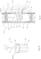
- Fig. 5a shows a perspective view of a seed/plant cup 25 and Fig. 5b shows a partial enlarged section of a seed/plant cup 25 inserted into a modular elongated, single-sided wall panel 9.
- the principle is equally applicable to a double-sided wall panel 10.
- Fig. 5a shows a perspective view of a seed/plant cup 25 with a plant 21 planted in the cup's 25 plant bedding material 26.
- the figure shown has a top mounting ring 28 configured to extend out from the surface of a solid or the acoustic board 6, 7 while the concealed portion of the cup 25 is configured to decline through the casing 30 opening 32 into the opening 27 in the plant bedding material tile 22.
- the cup's 25 dimensions can be configured to match standard industry cup dimensions as sold in major national home and garden stores. In fact, this innovation foresees home and garden stores' nurseries providing the seed/plant cups 25 to consumers.
- the seed/plant cup 25 can be made of organic or non-organic material with perforated openings 34 to enable the plant's roots 23 to grow into the plant bedding material tile 22 inside the wall panel 1.
- the edges 35 of the perforated openings 34 in the seed and plant cups 25 can be sharp.
- protrusion tab/s 29 built into the seed/plant cup 25 top ring 28 can enable rotating the seed/plant cup 25 about the cup's 25 central axis.
- Fig. 5b shows a transverse section of a partial single-sided wall panel arrangement 1.
- the elongated C-shaped wall panel 9 with an exemplary arrangement comprises a plant bedding material tile 22 retained inside a casing 30 which in turn is coupled to a solid or acoustic board 6; 7.
- a seed/plant cup 25 is shown inserted through an opening 32 in the exterior face of the board 6, 7 into a corresponding cup bedding material opening 27 in the plant bedding material tile 22.
- the present figure shows an irrigation pipe 36 coupled to a bottom face of a top flange 2 of the elongated wall panel 9.
- the irrigation pipe 36 with an irrigation nozzle 37 is disposed in a mechanical key 5 formed in the flange 2.
- Irrigation fluid 20 conveyed through the irrigation pipe 36 is emitted onto a funnel 40 that carries the fluid 20 to the root base 23 of the seed/plant cup and/or its vicinity.
- the irrigation fluid can saturate the plant bedding material tile 22 with fluid flowing from the top of the plant bedding material tile 22 to below or, as shown in this figure, can be directed through the funnel 40 to arrive in proximity to a seed/plant cup 25 root base structure 23. From there fluid can travel in all directions inside the plant bedding material tile 22.
- This method can save irrigation fluid 20 and reduce root proliferation across the bedding material tile 22.
- the fluid is instead configured to flow from the top surface of the bedding material tile 22 downwardly.
- the one or more funnels 40 are preferably configured to be substantially vertically aligned with the one or more cup bedding material openings 27 in the plant bedding material tile 22.
- Other elements shown include an irrigation pipe 36 with an irrigation nozzle 37, a coupling fastener 19 that couples the casing 30 of the plant bedding material tile 22 to the solid/acoustic board 6, 7, and mechanical fasteners 14 coupling the board 6, 7 to the top flange 2 of the elongated wall panel 9.
- Fig. 5b discloses as single-sided elongated wall panel 9, the same principle is equally applicable to a double-sided wall panel 10.
- top and bottom flanges comprise weep holes 41 allowing a draining of irrigation fluid.
- Figs. 6a and 6b show in perspective view mechanical means to couple the plant bedding material casing 30 to a board and a single-sided elongated wall panel 9, respectively.
- Figs. 6a and 6b illustrate an acoustic board, the same principle is equally applicable to a solid board.
- Fig. 6a shows in perspective view an exemplary means to couple a plant bedding material casing 30 to a board 6, 7.
- the present figure shows continuous strips of Velcro-type fasteners 19 longitudinally disposed in proximity to the top and the bottom ends of the inner side of the board 6, 7, and reciprocating longitudinal fastener 19 strips in proximity to the exterior facing's top and the bottom of the plant bedding material casing 30.
- the arrangement allows for shipping the boards 6, 7 either coupled or not coupled to the plant bedding material casing 30.
- the plant bedding material tiles 22 can be shipped disposed inside their respective casings 30, or instead, to be mounted with the casings 30 in the field.
- the plant bedding material tile 22 or the plant bedding material tile 22 with its casing 30 can be detached and replaced with new boards 6,7 and/or casings 30.
- Fig. 6b shows in perspective view a preferred means to couple a plant bedding material tile casing 30 to the vertical wall 4 of an elongated wall panel 9.
- a single-sided elongated wall panel 9 is illustrated, the principle is equally applicable to a double-sided elongated wall panel 10.
- the present figure shows continuous strips of Velcro-type fasteners 19 disposed in proximity to the longitudinal top and bottom ends of the back side of the plant bedding material casing 30 and reciprocating fastener 19 strips in proximity to the longitudinal top and bottom of the inner vertical wall 4 of the wall panel 9.
- the arrangement allows for shipping the panel wall 1, 9 with or without the plant bedding material casing 30 coupled, and with or without the plant bedding material tiles 22 disposed inside the casing 30.
- the bedding material casing 30 and/or the bedding material tile 22 is detachable and can be replaced.
- the present figure is primarily suited to applications where the board 6, 7 can be removed, thereby exposing the internal elements inside the wall panel 1, 9.
- the mounting methods described for Figs. 6a and 6b are exemplary methods.
- Other mounting methods for mounting the plant bedding material tile 22, the plant bedding material tile 22 inside the casing 30, and the solid or acoustic board 6, 7 can include at least one of: bonding, riveting, screwing, lamination, and spiking.
- the mounting methods are equally applicable in the event the elongated wall panel should be a double-sided wall panel 10.
- Figures 7a and 7b show exemplary methods of removable and fixed coupling of the solid/acoustic board 6, 7 to the flanges 2, 3 of the wall panel 1, respectively. Although the methods are illustrated in view of a single-sided wall panel 9, the mounting methods are equally applicable in the event the elongated wall panel should be a double-sided wall panel 10.
- Fig. 7a shows a transverse section of the wall panel 1 with an exemplary solid/acoustic board 6, 7.
- the board 6, 7 is coupled to a casing 30 containing the plant bedding material tile 22.
- the present figure shows the longitudinal bottom of a board 6, 7 resting inside a reciprocating channel 18 built into the bottom flange 3.
- at least one bore 13 in the board 6, 7 is configured to receive at least one fastening device 14 that fastens the board 6, 7 to a reciprocating receiving structure built into the top flange 2 of the wall panel 9 and/or directly coupled to it.
- This board 6, 7 mounting method enables coupling the solid or acoustic board 6, 7 with the plant bedding material tile 22 and casing 30 complete to the wall panel 1, 9.
- the installer then simply removes the at least one tamper proof or non-tamper proof mechanical fastening device 14 and pulls down the solid/acoustic board 6, 7 from the top side in a rotational, tilting motion as shown in the figure.
- a coupled enlargement shows in more detail the coupling detail of a board 6, 7 to the top and bottom flanges 2.
- Fig. 7b shows a transverse section of the elongated wall panel 9 with an exemplary solid/acoustic board 6, 7 coupled.
- the board 6, 7 can be coupled to the top and the bottom flanges 2, 3 of the wall panel 1.
- the present figure shows the top and the bottom longitudinal ends of the solid/acoustic board 6, 7 captured in a wedged manner inside the counter channels 18 formed in the top and bottom flanges 2, 3.
- This exemplary method to secure the solid or acoustic board 6, 7 to the wall panel 9 is one among several mounting methods that can be utilized. Common to all methods is that the solid or the acoustic board 6, 7 is secured in position during the process of erecting the modular wall 100. This method may require removing above wall panel/s if an interior element inside the wall panel 1 needs replacing.
- a coupled enlargement shows in more detail the coupling detail of a board 6, 7 to the top and bottom flanges 2, 3.
- the methods of mounting the solid or acoustic board 6, 7 to the wall panel 1, as shown in Figs. 7a and 7b , can include plant material tile 22 and/or plant bedding material tile 22 inside casing 30.
- the solid or acoustic board 6, 7 can only incorporate noise absorbing material and/or at least one device that must be out of reach inside the wall panel 1.
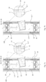
- Figs. 8a and 8b show partial sections of single- and double-sided wall panels 9, 10 with solid/acoustic boards 6, 7 and plant material 21.
- Fig. 8c shows a partial section of back-to-back, single-sided wall panels 9 with a gap 11 between two single-sided wall panels 9.
- Fig. 8a shows a partial transverse section of a single-sided elongated wall panel 9 with a plant bedding material tile 22 inside a casing 30 coupled to a solid/acoustic board 6, 7, with plants 21 growing from a seed/plant cup 25 at the modular wall's 100 exterior.
- the seed/plant cup 25 is inserted through an opening 32 in the board 6, 7, growing roots 23 inside the plant bedding material tile 22.
- the entire modular wall 100 described above is formed by coupling the same or different elongated wall panels 9 from above and below.
- the wall panels 9 are keyed to one another by a mechanical key 5 that can be configured into the profile of the top and/or the bottom flange/s 2, 3 of the wall panels 1.
- a continuous irrigation pipe 36 is shown with an irrigation nozzle 37.
- the irrigation pipe 36 shown is coupled to the bottom face of the top flange 2 of the wall panel 9.
- the irrigation pipe 36 can be disposed on the top surface of the bottom the wall panel 9 bottom flange 3.
- no irrigation pipe is needed, and the bottom flange 3 of the wall panel 1 conveys irrigation fluid 20 to the plant bedding material tile 22.
- Weep holes 41 are arranged in the top and bottom flanges 2, 3 allowing a flow of irrigation fluid between the stacked elongated wall panels 9.
- Fig. 8b shows a partial transverse wall panel section of a double-sided elongated wall panel 10 retaining at least one plant bedding material tile 22 and/or a solid or acoustic board 6, 7 on both sides of the modular wall 100. It is realized that one side can be provided with plant bedding material tiles 22 to allow cultivation, whereas the other side of the modular wall 100 can be provided with solid/acoustic panels 6, 7. In this figure, the plant material 21 can grow from both sides of the wall 10 wherein a common vertical wall 4 of the elongated wall panel 10 is disposed between the two openings retaining the plant bedding material tiles 22.
- Fig. 8c shows a partial transverse section of a wall with back-to-back single-sided wall panels 9, with an air gap 11 between.
- a barrier member 12 can be disposed between the vertical walls 4 of the wall panels 1, 9.
- the barrier member 12 can be selected to withstand ballistic projectiles, reduce sound transmittance, and incorporate sensing devices and/or other electronic or mechanical conductors requiring a chase.
- the entire wall assemblies 1 shown in Figs. 8a, 8b and 8c are wedged between flanges of vertical posts 8 disposed at both ends of the wall panels 1 that together comprise the modular wall 100 assembly
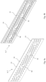
- Figs. 9a and 9b show front and back exploded perspective views of a section of the modular wall 100, wall panel 1 assembly with an irrigation pipe 36 and sound attenuation 39 strips, including the plant bedding material tile 22, the casing 30 with coupling fasteners 19, an acoustic board 7 with coupling fasteners 19, seed/plants cups 25, and mechanical fasteners 14 respectively.
- the elongated wall panels 9, 10 may comprise a plurality of plant bedding material tiles 22 and boards 6, 7 arranged side by side along their longitudinal directions.
- the tiles 22 and boards 6, 7 may each have a length that is substantially shorter than the respective elongated wall panel 9, 10.
- one and the same elongated wall panel 9, 10 may, along its longitudinal extension be provided with a mixture of plant bedding material tiles 22, sound attenuating material tiles, acoustic boards 7 and non-acoustic boards 6.
- the pattern of openings 50 in the acoustic boards 7 may vary. Also, the same sound attenuating effect may be achieved by recesses.
Landscapes
- Engineering & Computer Science (AREA)
- Architecture (AREA)
- Civil Engineering (AREA)
- Structural Engineering (AREA)
- Life Sciences & Earth Sciences (AREA)
- Environmental Sciences (AREA)
- Finishing Walls (AREA)
- Cultivation Receptacles Or Flower-Pots, Or Pots For Seedlings (AREA)
Claims (12)
- Modulares Wandsystem umfassend eine Vielzahl von übereinander angeordneten, länglichen Wandplatten (9; 10), einen Pflanzeneinbettungsmaterialblock (22), einen Samen-/Pflanzenbehälter (25), eine Platte (6; 7) und ein Bewässerungsrohr (36), wobei:die länglichen Wandplatten (9; 10) eine vertikale Wand (4), einen oberen Flansch (2) und einen unteren Flansch (3) umfassen;das Fluid abgebende Bewässerungsrohr (36) auf dem oberen und/oder dem unteren Flansch (2; 3) einer länglichen Wandplatte (9; 10) angeordnet und/oder mit diesem verbunden ist;die Platte (6; 7) mindestens eine Öffnung (32) umfasst, die zur Aufnahme eines Samen-/Pflanzenbehälters (25) konfiguriert ist, und wobei die Platte (6; 7) mit mindestens einem der Flansche (2; 3) der länglichen Wandplatte (9; 10) verbunden ist, wodurch ein Wandplatteninnenraum gebildet wird;der Pflanzeneinbettungsmaterialblock (22) konfiguriert ist, um mit einem inneren vertikalen Wandabschnitt (4) der länglichen Wandplatte (9; 10) und/oder mit einem inneren Wandabschnitt der Platte (6; 7) verbunden zu werden;der Samen-/Pflanzenbehälter (25) konfiguriert ist, um von außen durch die mindestens eine Öffnung (32) in der Platte (6; 7) eingesetzt zu werden, um dadurch teilweise in einer Behältereinbettungsmaterialöffnung (27) des Pflanzeneinbettungsmaterialblocks (22) angeordnet zu sein; und wobeinach der Bewässerung durch eine Fluidzufuhr, die durch das Fluid abgebende Bewässerungsrohr (36) bereitgestellt wird, ein Samen/eine Pflanze in dem Samen-/Pflanzenbehälter (25), der innerhalb des Pflanzeneinbettungsmaterialblocks (22) angeordnet ist, dazu ausgelegt ist, um Wurzeln in den Pflanzeneinbettungsmaterialblock (22) zu schlagen und ein Blätterdach zu bilden, das sich von einer Außenseite der Platte (6; 7) aus erstreckt.
- Modulares Wandsystem nach Anspruch 1, wobei es sich bei der Platte (6; 7) um eine Akustikplatte handelt oder wobei es sich bei der Platte nicht um eine Akustikplatte handelt.
- Modulares Wandsystem nach Anspruch 1, wobei die Platte (6; 7) mindestens eine schalldämmende Durchgangsöffnung (50) aufweist.
- Modulares Wandsystem nach Anspruch 1, wobei die Platte (6; 7) eine Bohrung (13) aufweist, die konfiguriert ist, um die Platte (6; 7) mittels eines mechanischen Befestigungsmittels (14) mit der länglichen Wandplatte (9; 10) zu verbinden.
- Modulares Wandsystem nach Anspruch 1, wobei die Platte (6; 7) zwischen dem oberen und unteren Flansch (2; 3) der länglichen Wandplatte (9; 10) lösbar befestigt ist.
- Modulares Wandsystem nach Anspruch 1, wobei das modulare Wandsystem mindestens zwei einseitige oder doppelseitige längliche Wandplatten (9; 10) umfasst.
- Modulares Wandsystem nach Anspruch 1, wobei ein Flansch (2; 3) einer ersten länglichen Wandplatte (9; 10) konfiguriert ist, um durch mindestens einen hin- und hergehenden mechanischen Schlüssel (5) mit einem Flansch (2; 3) einer zweiten länglichen Wandplatte (9; 10) verbunden zu sein.
- Modulares Wandsystem nach Anspruch 1, wobei der obere und der untere Flansch (2; 3) der länglichen Wandplatte (9; 10) ein oder mehrere Ablauflöcher (41) umfassen.
- Modulares Wandsystem nach Anspruch 1, wobei der Pflanzeneinbettungsmaterialblock (22) mindestens einen Trichter (40) umfasst, wobei der eine oder die mehreren Trichter konfiguriert sind, um im Wesentlichen vertikal zu einer entsprechenden Behältereinbettungsmaterialöffnung (27) in dem Pflanzeneinbettungsmaterialblock 22 ausgerichtet zu sein.
- Modulares Wandsystem nach Anspruch 1, wobei der Pflanzeneinbettungsmaterialblock (22) konfiguriert ist, um mit der Platte (6; 7) und/oder einer Pflanzeneinbettungsmaterialummantelung (30) verbunden zu sein.
- Modulare Wand (100), gebildet durch die Verwendung eines modularen Wandsystems nach einem der Ansprüche 1 bis 10, wobei die Vielzahl von länglichen Wandplatten (9; 10) zwischen mindestens zwei vertikal verlaufenden Pfosten (8) in gestapelter Beziehung übereinander angeordnet ist.
- Modulare Wand nach Anspruch 11, wobei die modulare Wand (100) von mindestens zwei einseitigen oder doppelseitigen länglichen Wandplatten (9; 10) gebildet ist und wobei mindestens eine der Seiten der modularen Wand (100) eine Vielzahl von Samen-/Pflanzenbehältern (25) umfasst.
Priority Applications (4)
| Application Number | Priority Date | Filing Date | Title |
|---|---|---|---|
| EP25152256.1A EP4578272A1 (de) | 2022-09-02 | 2022-09-02 | Modulares wandsystem und modulare wand |
| EP22193649.5A EP4331348B1 (de) | 2022-09-02 | 2022-09-02 | Modulares wandsystem und modulare wand |
| US19/101,896 US20260053099A1 (en) | 2022-09-02 | 2023-08-30 | A modular wall system and a modular wall |
| PCT/IB2023/058558 WO2024047544A1 (en) | 2022-09-02 | 2023-08-30 | A modular wall system and a modular wall |
Applications Claiming Priority (1)
| Application Number | Priority Date | Filing Date | Title |
|---|---|---|---|
| EP22193649.5A EP4331348B1 (de) | 2022-09-02 | 2022-09-02 | Modulares wandsystem und modulare wand |
Related Child Applications (2)
| Application Number | Title | Priority Date | Filing Date |
|---|---|---|---|
| EP25152256.1A Division-Into EP4578272A1 (de) | 2022-09-02 | 2022-09-02 | Modulares wandsystem und modulare wand |
| EP25152256.1A Division EP4578272A1 (de) | 2022-09-02 | 2022-09-02 | Modulares wandsystem und modulare wand |
Publications (3)
| Publication Number | Publication Date |
|---|---|
| EP4331348A1 EP4331348A1 (de) | 2024-03-06 |
| EP4331348B1 true EP4331348B1 (de) | 2025-02-19 |
| EP4331348C0 EP4331348C0 (de) | 2025-02-19 |
Family
ID=83191865
Family Applications (2)
| Application Number | Title | Priority Date | Filing Date |
|---|---|---|---|
| EP22193649.5A Active EP4331348B1 (de) | 2022-09-02 | 2022-09-02 | Modulares wandsystem und modulare wand |
| EP25152256.1A Pending EP4578272A1 (de) | 2022-09-02 | 2022-09-02 | Modulares wandsystem und modulare wand |
Family Applications After (1)
| Application Number | Title | Priority Date | Filing Date |
|---|---|---|---|
| EP25152256.1A Pending EP4578272A1 (de) | 2022-09-02 | 2022-09-02 | Modulares wandsystem und modulare wand |
Country Status (3)
| Country | Link |
|---|---|
| US (1) | US20260053099A1 (de) |
| EP (2) | EP4331348B1 (de) |
| WO (1) | WO2024047544A1 (de) |
Citations (2)
| Publication number | Priority date | Publication date | Assignee | Title |
|---|---|---|---|---|
| WO2017170583A1 (ja) * | 2016-03-31 | 2017-10-05 | 大和ハウス工業株式会社 | 空気浄化緑化装置 |
| KR20190040147A (ko) * | 2019-03-29 | 2019-04-17 | 전태평 | 공기 정화 기능을 포함하는 벽면 조경용 화분 |
Family Cites Families (84)
| Publication number | Priority date | Publication date | Assignee | Title |
|---|---|---|---|---|
| US2279735A (en) * | 1938-05-27 | 1942-04-14 | Noel Wright Gates | Vegetation-bearing display surface and system |
| US4255896A (en) * | 1979-06-12 | 1981-03-17 | Carl Vincent P | Hydroponic growing apparatus |
| GB2157737A (en) * | 1984-04-19 | 1985-10-30 | Audrey Jane Ryder | Bricks and plant holder |
| GB8928485D0 (en) * | 1989-12-18 | 1990-02-21 | Caddy John F | A plant container for use in cladding a vertical surface |
| US5287650A (en) * | 1990-10-08 | 1994-02-22 | Asanuma Corporation | Structured medium for the cultivation of greenery and a waterproofing system to facilitate the installation of said medium on buildings |
| US5361537A (en) * | 1992-06-23 | 1994-11-08 | Wolfgang Behrens | Noise protection wall |
| FR2860022B1 (fr) * | 2003-09-18 | 2005-11-25 | Jean Francois Daures | Structure modulaire pour l'amenagement d'une paroi sensiblement verticale d'un bati, pour la reception de vegetaux d'ornement |
| WO2005116347A1 (en) * | 2004-05-27 | 2005-12-08 | Jeung Su Lee | Plantable reinforced earth wall and its block and construction method of reinforced earth wall. |
| FR2872381B1 (fr) * | 2004-06-30 | 2007-12-07 | Canevaflor Soc Par Actions Sim | Structure pour mur vegetalise |
| FR2872382B1 (fr) * | 2004-06-30 | 2007-12-14 | Soprema Sa | Dispositif de vegetalisation modulaire pour facades, murs ou analogues |
| WO2006073001A1 (ja) * | 2005-01-07 | 2006-07-13 | Sugikou Co., Ltd. | 緑化仮設構造体 |
| JP2006280285A (ja) * | 2005-03-31 | 2006-10-19 | Daiwa House Ind Co Ltd | 垂直面等の立ち上がり面用の緑化構造及び給水マット |
| FR2889406B1 (fr) * | 2005-08-02 | 2007-11-23 | Greenwall S A S Soc Par Action | Paroi vegetalisee et elements constitutifs. |
| ITPI20070062A1 (it) * | 2007-05-25 | 2008-11-26 | Maurizio Pacini | Sistema per realizzare tappeti erbosi ed altre superfici vegetate in qualsiasi posizione spaziale mediante l'impiego di elementi modulari e sistemi di fissaggio |
| US9730395B2 (en) * | 2007-07-11 | 2017-08-15 | Gary R. Hartman | Modular growing panel system and method for covering structures with vegetation |
| CA2606938A1 (fr) * | 2007-10-17 | 2009-04-17 | Eric Bond | Systeme modulaire de vegetalisation extensive-intensive |
| MX2010005118A (es) * | 2007-11-08 | 2010-06-25 | Francisco Ruiz Caballero | Bandeja y panel vegetal. |
| KR100989705B1 (ko) * | 2008-02-12 | 2010-10-26 | 송웅호 | 벽걸이형 화분장치 |
| US20090307972A1 (en) * | 2008-06-11 | 2009-12-17 | Ottevanger Rene | Substrate for plants in an aquarium, terrarium and the like |
| US7921599B2 (en) * | 2008-10-07 | 2011-04-12 | George A. Irwin | Vegetation support system |
| US20110146147A1 (en) * | 2008-10-07 | 2011-06-23 | George A Irwin | Vegetation support system |
| US20120222352A1 (en) * | 2009-08-28 | 2012-09-06 | Dartdijk N.V. | Growth device for crop and cladding or construction part manufactured therewith |
| US7926224B1 (en) * | 2009-10-20 | 2011-04-19 | Victory Greenwall Systems, Inc. | Green wall planting module, support structure and irrigation control system |
| US20110094153A1 (en) * | 2009-10-27 | 2011-04-28 | Astral Property Pty Ltd | Vertical wall garden |
| GB2475101B (en) * | 2009-11-09 | 2014-01-08 | Mark Laurence | Wall for growing plants |
| KR20110061032A (ko) * | 2009-12-01 | 2011-06-09 | 이애연 | 친환경적인 식생 옹벽블록 및 그 제조방법 |
| JP5578605B2 (ja) * | 2009-12-17 | 2014-08-27 | アースコンシャス株式会社 | 壁面緑化パネル |
| US20110225883A1 (en) * | 2010-03-16 | 2011-09-22 | Cliffords Perennial And Vine Inc | Vegetation wall |
| WO2011136842A1 (en) * | 2010-04-26 | 2011-11-03 | Baker Richard L | Vertical planter |
| FR2959387A1 (fr) * | 2010-04-28 | 2011-11-04 | Sidelsky David Daniel Gilles | Cloture vegetale modulaire - dispositif modulaire permettant la culture de vegetaux de facon verticale dans une suite de modules disposes sous forme de cloture entre des poteaux. |
| DE102010045666B4 (de) * | 2010-09-17 | 2012-05-16 | Zinco Gmbh | Begrünungssystem zur Begrünung von vertikalen und geneigten Flächen |
| FR2968890A1 (fr) * | 2010-12-16 | 2012-06-22 | Laurent Frehaut | Dispositif de culture de vegetaux, cartouche vegetale et colonne vegetale |
| GB2486886B (en) * | 2010-12-23 | 2012-12-19 | James Castro-Edwards | Plant wall system |
| FR2976769A1 (fr) * | 2011-06-23 | 2012-12-28 | Benjamin Dubois | Tableau vegetal |
| KR101247608B1 (ko) * | 2011-09-07 | 2013-04-02 | (주) 삼전건설 | 고로슬래그를 이용한 친환경 보강토 옹벽블록 |
| US20130118074A1 (en) * | 2011-11-10 | 2013-05-16 | Steven FULBROOK | Hydroponic modular planting system |
| US20150237811A1 (en) * | 2011-11-15 | 2015-08-27 | Living Systems, Inc. | Modular system for plant growth and air purification |
| US9462755B1 (en) * | 2012-02-22 | 2016-10-11 | EcoWalls, LLC | Modular wall assembly for promoting vertical vegetative growth |
| US9210846B2 (en) * | 2012-02-28 | 2015-12-15 | Joseph P. VanLente | Vertical concentrated vegetable and plant grower |
| FI126092B (en) * | 2012-03-28 | 2016-06-30 | Teknologian Tutkimuskeskus Vtt Oy | peat structures |
| KR101240481B1 (ko) * | 2012-05-04 | 2013-03-06 | (주) 청연 | 공기 청정용 벽체 |
| CN202750524U (zh) * | 2012-06-26 | 2013-02-27 | 宁波微雨节水灌溉制品有限公司 | 一种绿墙 |
| US9351448B2 (en) * | 2012-09-25 | 2016-05-31 | Hortech, Inc. | Wall planting system |
| GB2507372A (en) * | 2012-10-23 | 2014-04-30 | Gerald Sung | Green wall planting support apparatus |
| DE202012104884U1 (de) * | 2012-12-14 | 2013-02-13 | Stefan Brandhorst | Vertikalbegrünungssystem |
| FR3000872B1 (fr) * | 2013-01-16 | 2015-08-07 | Jungle Art | Panneau modulaire de dispositif de culture vegetale en hydroponie |
| IN2013MU01357A (de) * | 2013-04-11 | 2015-04-10 | Kumarpal Shah | |
| CN103262762B (zh) * | 2013-05-30 | 2016-01-27 | 苏州汇诚智造工业设计有限公司 | 一种空瓶绿化墙体固定座及其制造方法 |
| US9807946B2 (en) * | 2013-07-12 | 2017-11-07 | Pride Garden Products | Vertical living wall planter |
| CN203608609U (zh) * | 2013-11-06 | 2014-05-28 | 赵艳丽 | 一种模块式垂直绿化系统 |
| JP2015130848A (ja) * | 2014-01-15 | 2015-07-23 | サントリーホールディングス株式会社 | 植栽ユニット及び植栽具 |
| DE102014004270A1 (de) * | 2014-02-10 | 2015-08-13 | Berthold Adler | Bauelement und System zur vertikalen Begrünung |
| US9706719B2 (en) * | 2014-03-06 | 2017-07-18 | Ryan Haas | Water containment system |
| US20150289452A1 (en) * | 2014-03-14 | 2015-10-15 | Yale University | Modular Living Green Wall System to Provide Heat Rejection |
| BE1023546B1 (fr) * | 2015-04-07 | 2017-04-28 | Sous Les Fraises Sas | Supports pour cultiver un organisme, utilisations desdits supports et methodes de culture et d'epuration utilsant ces supports |
| KR101568638B1 (ko) * | 2015-05-26 | 2015-11-11 | 서형석 | 도시녹화를 위한 건물의 실내외 녹화용 식생보드 |
| MA40728A (fr) * | 2015-10-20 | 2017-06-13 | Tower Garden Llc | Appareil amélioré de culture hydroponique de plantes |
| FR3047498A1 (fr) * | 2016-02-08 | 2017-08-11 | Pierre Yves Jorcin | Le mur jardin = modules permettant de realiser des murs porteurs destines a etre vegetalises |
| US9883642B2 (en) * | 2016-06-14 | 2018-02-06 | Freight Farms, Inc. | Vertical assembly for growing plants |
| GB201611220D0 (en) * | 2016-06-28 | 2016-08-10 | Ove Arup Partnership Ltd | Flexible layered sheet |
| CN206285697U (zh) * | 2016-08-18 | 2017-06-30 | 安徽希美生态环保科技有限公司 | 一种植物幕墙 |
| US10285336B2 (en) * | 2016-08-18 | 2019-05-14 | Formgardens, Inc. | Plant container assembly with nested growth substrates |
| US10130045B2 (en) * | 2017-01-13 | 2018-11-20 | Lazaro Balseiro | Living art frame |
| DE102017204674A1 (de) * | 2017-03-21 | 2018-09-27 | Robert Bosch Gmbh | Gebäudeelement, Gebäude und Verfahren zu dessen Herstellung |
| CN107409807A (zh) * | 2017-03-30 | 2017-12-01 | 江苏云耕科技有限公司 | 一种新型空气过滤自吸水式植物墙 |
| US11122748B2 (en) * | 2017-05-08 | 2021-09-21 | Daniel S. Spiro | Automated outdoor modular vertical plant cultivation system |
| US11147215B2 (en) * | 2017-05-08 | 2021-10-19 | Daniel S. Spiro | Automated outdoor modular vertical plant cultivation system |
| US11778955B2 (en) * | 2017-11-29 | 2023-10-10 | Urban Planter, Llc | Automated vertical plant cultivation system |
| CN108040673B (zh) * | 2017-12-09 | 2020-04-17 | 温州振东园林工程有限公司 | 一种垂直绿化植物幕墙施工方法 |
| KR101982449B1 (ko) * | 2018-08-20 | 2019-05-24 | 전태평 | 공기 정화 기능을 포함하는 벽면 조경용 화분 |
| DE102019201992A1 (de) * | 2019-02-14 | 2020-08-20 | Deutsches Zentrum für Luft- und Raumfahrt e.V. | Fassadenelement für eine Gebäudewand mit Pflanzbehältnis für Pflanzen, Fassadensystem sowie Verfahren zur Nährstoffversorgung von Pflanzen eines Fassadenelements |
| CN110447422A (zh) * | 2019-08-16 | 2019-11-15 | 深圳市翠箓科技绿化工程有限公司 | 一种组合式垂直绿化装置 |
| DE102019005807A1 (de) * | 2019-08-19 | 2021-02-25 | Bernd Friemuth | Plattenförmiges Isolierelement |
| KR102284174B1 (ko) * | 2021-01-05 | 2021-07-29 | 전태평 | 벽면 조경용 종이화분을 이용한 공기정화장치 |
| US20220304249A1 (en) * | 2021-03-29 | 2022-09-29 | Christopher Todd Wente | Modular ecological system for walls |
| EP4186353A1 (de) * | 2021-11-30 | 2023-05-31 | Antonia Ablaß | Modul zur aufnahme von pflanzen |
| US20250031642A1 (en) * | 2021-12-10 | 2025-01-30 | Green Being Societa' Benefit A Responsabilita' Limitata | Indoor systems for making self-sufficient green walls and processes for growing the green walls |
| FR3120242B1 (fr) * | 2022-04-27 | 2025-06-27 | Vertige Int | Module de mur végétalisé |
| US20240023494A1 (en) * | 2022-07-20 | 2024-01-25 | David Brenner | Modular living wall system |
| FR3140894B1 (fr) * | 2022-10-17 | 2025-10-24 | On Scenes | Module végétal isolant pour murs et toitures de bâtiments |
| CN116138070B (zh) * | 2022-12-05 | 2024-02-02 | 北方工业大学 | 一种互嵌式砌筑型立体绿化模块 |
| DE102023003886A1 (de) * | 2023-09-25 | 2025-03-27 | Brigitte Friemuth | Plattenförmiges element aus polystyrol schaumstoff |
| EP4533939A1 (de) * | 2023-10-05 | 2025-04-09 | Joachim Geiger | Fassadenelement zur begrünung von fassaden |
| EP4635291A1 (de) * | 2024-04-18 | 2025-10-22 | On-Scènes | Begrüntes isoliermodul für gebäudefassaden und -dächer |
-
2022
- 2022-09-02 EP EP22193649.5A patent/EP4331348B1/de active Active
- 2022-09-02 EP EP25152256.1A patent/EP4578272A1/de active Pending
-
2023
- 2023-08-30 US US19/101,896 patent/US20260053099A1/en active Pending
- 2023-08-30 WO PCT/IB2023/058558 patent/WO2024047544A1/en not_active Ceased
Patent Citations (2)
| Publication number | Priority date | Publication date | Assignee | Title |
|---|---|---|---|---|
| WO2017170583A1 (ja) * | 2016-03-31 | 2017-10-05 | 大和ハウス工業株式会社 | 空気浄化緑化装置 |
| KR20190040147A (ko) * | 2019-03-29 | 2019-04-17 | 전태평 | 공기 정화 기능을 포함하는 벽면 조경용 화분 |
Also Published As
| Publication number | Publication date |
|---|---|
| EP4331348A1 (de) | 2024-03-06 |
| WO2024047544A1 (en) | 2024-03-07 |
| US20260053099A1 (en) | 2026-02-26 |
| EP4331348C0 (de) | 2025-02-19 |
| EP4578272A1 (de) | 2025-07-02 |
Similar Documents
| Publication | Publication Date | Title |
|---|---|---|
| EP0697051B1 (de) | Unterdecke | |
| US11778955B2 (en) | Automated vertical plant cultivation system | |
| CN101326891B (zh) | 植被墙结构 | |
| CN102458095B (zh) | 植生板、制作方法以及利用此方法的自然绿化系统 | |
| JP2014502842A (ja) | 内部空気循環を有する緑化壁 | |
| EP4331348B1 (de) | Modulares wandsystem und modulare wand | |
| JP6169389B2 (ja) | 壁面緑化大気浄化装置 | |
| JP4108198B2 (ja) | 緑化パネル、緑化方法及び折版屋根の構造 | |
| WO1994024382A1 (de) | Unterdecke | |
| CN116479855A (zh) | 一种用于沙漠治理的防风固沙装置 | |
| KR20150146001A (ko) | 컨테이너형 소형식물 재배시스템 | |
| CN202026633U (zh) | 隔热保温栽植盘 | |
| CN102204482B (zh) | 蓄水阻根隔热保温栽植盘 | |
| EP1341969B1 (de) | Schallschluck- oder -reduzierungsschirm | |
| KR100463394B1 (ko) | 식생 방음벽 시공용 철망 블럭 | |
| CN212573663U (zh) | 一种具有隔音功能的市政用绿化带 | |
| CN216551991U (zh) | 一种生态治理用水土保持边坡保护结构 | |
| KR100480835B1 (ko) | 철망 블럭을 이용한 식생 방음벽 | |
| KR200291855Y1 (ko) | 철망 블럭을 이용한 식생 방음벽 | |
| CN214383988U (zh) | 室内轻质隔墙板 | |
| US20250318477A1 (en) | Non-combustible modular living wall system | |
| JP2002125469A (ja) | 建築物の化粧柱構造 | |
| KR20030025970A (ko) | 환경 친화성 녹화방음벽 | |
| KR100639515B1 (ko) | 흡습수단을 구비한 건축/가구용 자재 | |
| DE19707299A1 (de) | Begrünbare Schallschutzwand |
Legal Events
| Date | Code | Title | Description |
|---|---|---|---|
| STAA | Information on the status of an ep patent application or granted ep patent |
Free format text: STATUS: EXAMINATION IS IN PROGRESS |
|
| PUAI | Public reference made under article 153(3) epc to a published international application that has entered the european phase |
Free format text: ORIGINAL CODE: 0009012 |
|
| 17P | Request for examination filed |
Effective date: 20230505 |
|
| AK | Designated contracting states |
Kind code of ref document: A1 Designated state(s): AL AT BE BG CH CY CZ DE DK EE ES FI FR GB GR HR HU IE IS IT LI LT LU LV MC MK MT NL NO PL PT RO RS SE SI SK SM TR |
|
| GRAP | Despatch of communication of intention to grant a patent |
Free format text: ORIGINAL CODE: EPIDOSNIGR1 |
|
| STAA | Information on the status of an ep patent application or granted ep patent |
Free format text: STATUS: GRANT OF PATENT IS INTENDED |
|
| INTG | Intention to grant announced |
Effective date: 20240402 |
|
| GRAJ | Information related to disapproval of communication of intention to grant by the applicant or resumption of examination proceedings by the epo deleted |
Free format text: ORIGINAL CODE: EPIDOSDIGR1 |
|
| STAA | Information on the status of an ep patent application or granted ep patent |
Free format text: STATUS: EXAMINATION IS IN PROGRESS |
|
| INTC | Intention to grant announced (deleted) | ||
| GRAP | Despatch of communication of intention to grant a patent |
Free format text: ORIGINAL CODE: EPIDOSNIGR1 |
|
| STAA | Information on the status of an ep patent application or granted ep patent |
Free format text: STATUS: GRANT OF PATENT IS INTENDED |
|
| INTG | Intention to grant announced |
Effective date: 20240912 |
|
| GRAS | Grant fee paid |
Free format text: ORIGINAL CODE: EPIDOSNIGR3 |
|
| GRAA | (expected) grant |
Free format text: ORIGINAL CODE: 0009210 |
|
| STAA | Information on the status of an ep patent application or granted ep patent |
Free format text: STATUS: THE PATENT HAS BEEN GRANTED |
|
| AK | Designated contracting states |
Kind code of ref document: B1 Designated state(s): AL AT BE BG CH CY CZ DE DK EE ES FI FR GB GR HR HU IE IS IT LI LT LU LV MC MK MT NL NO PL PT RO RS SE SI SK SM TR |
|
| REG | Reference to a national code |
Ref country code: GB Ref legal event code: FG4D |
|
| REG | Reference to a national code |
Ref country code: CH Ref legal event code: EP |
|
| REG | Reference to a national code |
Ref country code: DE Ref legal event code: R096 Ref document number: 602022010742 Country of ref document: DE |
|
| REG | Reference to a national code |
Ref country code: IE Ref legal event code: FG4D |
|
| U01 | Request for unitary effect filed |
Effective date: 20250219 |
|
| U07 | Unitary effect registered |
Designated state(s): AT BE BG DE DK EE FI FR IT LT LU LV MT NL PT RO SE SI Effective date: 20250225 |
|
| PG25 | Lapsed in a contracting state [announced via postgrant information from national office to epo] |
Ref country code: RS Free format text: LAPSE BECAUSE OF FAILURE TO SUBMIT A TRANSLATION OF THE DESCRIPTION OR TO PAY THE FEE WITHIN THE PRESCRIBED TIME-LIMIT Effective date: 20250519 |
|
| PG25 | Lapsed in a contracting state [announced via postgrant information from national office to epo] |
Ref country code: PL Free format text: LAPSE BECAUSE OF FAILURE TO SUBMIT A TRANSLATION OF THE DESCRIPTION OR TO PAY THE FEE WITHIN THE PRESCRIBED TIME-LIMIT Effective date: 20250219 |
|
| PG25 | Lapsed in a contracting state [announced via postgrant information from national office to epo] |
Ref country code: ES Free format text: LAPSE BECAUSE OF FAILURE TO SUBMIT A TRANSLATION OF THE DESCRIPTION OR TO PAY THE FEE WITHIN THE PRESCRIBED TIME-LIMIT Effective date: 20250219 |
|
| PG25 | Lapsed in a contracting state [announced via postgrant information from national office to epo] |
Ref country code: NO Free format text: LAPSE BECAUSE OF FAILURE TO SUBMIT A TRANSLATION OF THE DESCRIPTION OR TO PAY THE FEE WITHIN THE PRESCRIBED TIME-LIMIT Effective date: 20250519 Ref country code: IS Free format text: LAPSE BECAUSE OF FAILURE TO SUBMIT A TRANSLATION OF THE DESCRIPTION OR TO PAY THE FEE WITHIN THE PRESCRIBED TIME-LIMIT Effective date: 20250619 |
|
| PG25 | Lapsed in a contracting state [announced via postgrant information from national office to epo] |
Ref country code: HR Free format text: LAPSE BECAUSE OF FAILURE TO SUBMIT A TRANSLATION OF THE DESCRIPTION OR TO PAY THE FEE WITHIN THE PRESCRIBED TIME-LIMIT Effective date: 20250219 |
|
| PG25 | Lapsed in a contracting state [announced via postgrant information from national office to epo] |
Ref country code: GR Free format text: LAPSE BECAUSE OF FAILURE TO SUBMIT A TRANSLATION OF THE DESCRIPTION OR TO PAY THE FEE WITHIN THE PRESCRIBED TIME-LIMIT Effective date: 20250520 |
|
| U20 | Renewal fee for the european patent with unitary effect paid |
Year of fee payment: 4 Effective date: 20250815 |
|
| PG25 | Lapsed in a contracting state [announced via postgrant information from national office to epo] |
Ref country code: SM Free format text: LAPSE BECAUSE OF FAILURE TO SUBMIT A TRANSLATION OF THE DESCRIPTION OR TO PAY THE FEE WITHIN THE PRESCRIBED TIME-LIMIT Effective date: 20250219 |
|
| PG25 | Lapsed in a contracting state [announced via postgrant information from national office to epo] |
Ref country code: CZ Free format text: LAPSE BECAUSE OF FAILURE TO SUBMIT A TRANSLATION OF THE DESCRIPTION OR TO PAY THE FEE WITHIN THE PRESCRIBED TIME-LIMIT Effective date: 20250219 |
|
| PG25 | Lapsed in a contracting state [announced via postgrant information from national office to epo] |
Ref country code: SK Free format text: LAPSE BECAUSE OF FAILURE TO SUBMIT A TRANSLATION OF THE DESCRIPTION OR TO PAY THE FEE WITHIN THE PRESCRIBED TIME-LIMIT Effective date: 20250219 |
|
| PLBE | No opposition filed within time limit |
Free format text: ORIGINAL CODE: 0009261 |
|
| STAA | Information on the status of an ep patent application or granted ep patent |
Free format text: STATUS: NO OPPOSITION FILED WITHIN TIME LIMIT |
|
| 26N | No opposition filed |
Effective date: 20251120 |