EP4329129A2 - Energieverwaltungseinheit zur verwaltung elektrischer vorrichtungen und verfahren zur energieverwaltung elektrischer vorrichtungen - Google Patents
Energieverwaltungseinheit zur verwaltung elektrischer vorrichtungen und verfahren zur energieverwaltung elektrischer vorrichtungen Download PDFInfo
- Publication number
- EP4329129A2 EP4329129A2 EP23193506.5A EP23193506A EP4329129A2 EP 4329129 A2 EP4329129 A2 EP 4329129A2 EP 23193506 A EP23193506 A EP 23193506A EP 4329129 A2 EP4329129 A2 EP 4329129A2
- Authority
- EP
- European Patent Office
- Prior art keywords
- data
- energy management
- electric devices
- management unit
- unit
- Prior art date
- Legal status (The legal status is an assumption and is not a legal conclusion. Google has not performed a legal analysis and makes no representation as to the accuracy of the status listed.)
- Pending
Links
- 238000000034 method Methods 0.000 title claims abstract description 20
- 238000005259 measurement Methods 0.000 claims abstract description 40
- 230000005611 electricity Effects 0.000 claims abstract description 23
- 238000007599 discharging Methods 0.000 claims description 4
- XAGFODPZIPBFFR-UHFFFAOYSA-N aluminium Chemical compound [Al] XAGFODPZIPBFFR-UHFFFAOYSA-N 0.000 claims description 2
- 229910052782 aluminium Inorganic materials 0.000 claims description 2
- 239000004411 aluminium Substances 0.000 claims description 2
- 238000010438 heat treatment Methods 0.000 description 7
- 238000010586 diagram Methods 0.000 description 4
- 238000009826 distribution Methods 0.000 description 3
- 238000004519 manufacturing process Methods 0.000 description 3
- 238000004146 energy storage Methods 0.000 description 2
- 208000032544 Cicatrix Diseases 0.000 description 1
- 206010039580 Scar Diseases 0.000 description 1
- 230000003213 activating effect Effects 0.000 description 1
- 238000004378 air conditioning Methods 0.000 description 1
- 238000004891 communication Methods 0.000 description 1
- 208000014745 severe cutaneous adverse reaction Diseases 0.000 description 1
- 238000003860 storage Methods 0.000 description 1
Images


Classifications
-
- H—ELECTRICITY
- H02—GENERATION; CONVERSION OR DISTRIBUTION OF ELECTRIC POWER
- H02J—CIRCUIT ARRANGEMENTS OR SYSTEMS FOR SUPPLYING OR DISTRIBUTING ELECTRIC POWER; SYSTEMS FOR STORING ELECTRIC ENERGY
- H02J3/00—Circuit arrangements for ac mains or ac distribution networks
- H02J3/12—Circuit arrangements for ac mains or ac distribution networks for adjusting voltage in ac networks by changing a characteristic of the network load
- H02J3/14—Circuit arrangements for ac mains or ac distribution networks for adjusting voltage in ac networks by changing a characteristic of the network load by switching loads on to, or off from, network, e.g. progressively balanced loading
-
- H—ELECTRICITY
- H02—GENERATION; CONVERSION OR DISTRIBUTION OF ELECTRIC POWER
- H02J—CIRCUIT ARRANGEMENTS OR SYSTEMS FOR SUPPLYING OR DISTRIBUTING ELECTRIC POWER; SYSTEMS FOR STORING ELECTRIC ENERGY
- H02J13/00—Circuit arrangements for providing remote indication of network conditions, e.g. an instantaneous record of the open or closed condition of each circuitbreaker in the network; Circuit arrangements for providing remote control of switching means in a power distribution network, e.g. switching in and out of current consumers by using a pulse code signal carried by the network
- H02J13/00006—Circuit arrangements for providing remote indication of network conditions, e.g. an instantaneous record of the open or closed condition of each circuitbreaker in the network; Circuit arrangements for providing remote control of switching means in a power distribution network, e.g. switching in and out of current consumers by using a pulse code signal carried by the network characterised by information or instructions transport means between the monitoring, controlling or managing units and monitored, controlled or operated power network element or electrical equipment
- H02J13/00028—Circuit arrangements for providing remote indication of network conditions, e.g. an instantaneous record of the open or closed condition of each circuitbreaker in the network; Circuit arrangements for providing remote control of switching means in a power distribution network, e.g. switching in and out of current consumers by using a pulse code signal carried by the network characterised by information or instructions transport means between the monitoring, controlling or managing units and monitored, controlled or operated power network element or electrical equipment involving the use of Internet protocols
-
- H—ELECTRICITY
- H02—GENERATION; CONVERSION OR DISTRIBUTION OF ELECTRIC POWER
- H02J—CIRCUIT ARRANGEMENTS OR SYSTEMS FOR SUPPLYING OR DISTRIBUTING ELECTRIC POWER; SYSTEMS FOR STORING ELECTRIC ENERGY
- H02J13/00—Circuit arrangements for providing remote indication of network conditions, e.g. an instantaneous record of the open or closed condition of each circuitbreaker in the network; Circuit arrangements for providing remote control of switching means in a power distribution network, e.g. switching in and out of current consumers by using a pulse code signal carried by the network
- H02J13/00006—Circuit arrangements for providing remote indication of network conditions, e.g. an instantaneous record of the open or closed condition of each circuitbreaker in the network; Circuit arrangements for providing remote control of switching means in a power distribution network, e.g. switching in and out of current consumers by using a pulse code signal carried by the network characterised by information or instructions transport means between the monitoring, controlling or managing units and monitored, controlled or operated power network element or electrical equipment
- H02J13/00022—Circuit arrangements for providing remote indication of network conditions, e.g. an instantaneous record of the open or closed condition of each circuitbreaker in the network; Circuit arrangements for providing remote control of switching means in a power distribution network, e.g. switching in and out of current consumers by using a pulse code signal carried by the network characterised by information or instructions transport means between the monitoring, controlling or managing units and monitored, controlled or operated power network element or electrical equipment using wireless data transmission
- H02J13/00024—Circuit arrangements for providing remote indication of network conditions, e.g. an instantaneous record of the open or closed condition of each circuitbreaker in the network; Circuit arrangements for providing remote control of switching means in a power distribution network, e.g. switching in and out of current consumers by using a pulse code signal carried by the network characterised by information or instructions transport means between the monitoring, controlling or managing units and monitored, controlled or operated power network element or electrical equipment using wireless data transmission by means of mobile telephony
-
- H—ELECTRICITY
- H02—GENERATION; CONVERSION OR DISTRIBUTION OF ELECTRIC POWER
- H02J—CIRCUIT ARRANGEMENTS OR SYSTEMS FOR SUPPLYING OR DISTRIBUTING ELECTRIC POWER; SYSTEMS FOR STORING ELECTRIC ENERGY
- H02J2310/00—The network for supplying or distributing electric power characterised by its spatial reach or by the load
- H02J2310/10—The network having a local or delimited stationary reach
- H02J2310/12—The local stationary network supplying a household or a building
- H02J2310/14—The load or loads being home appliances
-
- H—ELECTRICITY
- H02—GENERATION; CONVERSION OR DISTRIBUTION OF ELECTRIC POWER
- H02J—CIRCUIT ARRANGEMENTS OR SYSTEMS FOR SUPPLYING OR DISTRIBUTING ELECTRIC POWER; SYSTEMS FOR STORING ELECTRIC ENERGY
- H02J2310/00—The network for supplying or distributing electric power characterised by its spatial reach or by the load
- H02J2310/50—The network for supplying or distributing electric power characterised by its spatial reach or by the load for selectively controlling the operation of the loads
- H02J2310/56—The network for supplying or distributing electric power characterised by its spatial reach or by the load for selectively controlling the operation of the loads characterised by the condition upon which the selective controlling is based
- H02J2310/58—The condition being electrical
Definitions
- the present invention relates to the field of electric devices in general and to management and control of electric devices, and more particularly to an energy management unit for managing electric devices and a method for energy management of electric devices.
- the object of the invention is to introduce an energy management unit for managing electric devices and a method for energy management of electric devices, which would provide a better and more advanced overall energy management electric devices.
- Advantageous embodiments are furthermore presented.
- energy management unit for managing electric devices, which energy management unit is a cloud connected IoT device configured: to receive settings data, said settings data comprising the preset energy demand levels of said electric devices; to receive external data, said external data comprising the current and upcoming spot-price of electricity; to receive device data from said electric devices, said device data comprising status data and/or measurement data of said electric devices; to determine a management action schedule based on said settings data and on said external data and on said device data; and to manage said electric devices utilising said management action schedule.
- said energy management unit is configured to receive device data from an inverter unit, said device data comprising status data and/or measurement data of said inverter unit and/or status data and/or measurement data of a photovoltaic system and/or status data and/or measurement data of a battery unit; and said determined management action schedule is based on said settings data and on said external data and on said device data received from said electric devices and said device data received from said inverter unit; and said energy management unit is configured to manage said inverter unit for controlling said photovoltaic system and said battery unit utilising said management action schedule.
- said energy management unit is configured to receive user control data from a user apparatus.
- said energy management unit is configured to receive information from an external database server and to store information to an external database server.
- said energy management unit is configured to receive said external data from data providers and/or from an external database server.
- said energy management unit is configured to receive said settings data from an external database server and/or from a user apparatus.
- said status data comprises operational status data, charge level status data and/or energy demand level status data.
- said measurement data comprises ambient characteristics measurement data, charge level measurement data and/or energy demand level measurement data.
- said said electric devices are managed by changing the energy charging/discharging levels of said electric devices and/or said photovoltaic system and/or of said battery unit, and/or by switching on/off said electric devices and/or said photovoltaic system and/or said battery unit.
- said management action schedule comprises a time based schedule of management actions for said electric devices and/or said photovoltaic system and/or said battery unit.
- said energy management unit comprises a main/carrier board and a CPU plugged into said main/carrier board providing said CPU power and the connectivity, said main/carrier board assembled in an aluminium case.
- settings data is received by said energy management unit, said settings data comprising the preset energy demand levels of said electric devices; external data is received by said energy management unit, said external data comprising the current and upcoming spot-price of electricity; device data from said electric devices is received by said energy management unit, said device data comprising status data and/or measurement data of said electric devices; a management action schedule is determined based on said settings data and on said external data and on said device data; and said electric devices are managed utilising said management action schedule.
- device data from an inverter unit by said energy management unit comprising status data and/or measurement data of said inverter unit and/or status data and/or measurement data of a photovoltaic system and/or status data and/or measurement data of a battery unit; said management action schedule is determined based on said settings data and on said external data and on said device data received from said electric devices and said device data received from said inverter unit; and said inverter unit is managed by said energy management unit for controlling said photovoltaic system and/or status data and/or measurement data of a battery unit utilising said management action schedule.
- user control data from a user apparatus is received by said energy management unit.
- said management action schedule comprises an hourly schedule for management actions for said electric devices and/or said photovoltaic system and/or said battery unit.
- the energy management unit for managing electric devices is a cloud connected IoT device configured: to receive settings data, said settings data comprising the preset energy demand levels of said electric devices; to receive external data, said external data comprising the current and upcoming spot-price of electricity; to receive device data from said electric devices, said device data comprising status data and/or measurement data of said electric devices; to determine a management action schedule based on said settings data and on said external data and on said device data; and to manage said electric devices utilising said management action schedule.
- FIG. 1 illustrates an embodiment of an energy management unit according to the present invention in an arrangement comprising electric devices.
- the presented embodiment of an energy management unit 10 is a cloud connected IoT device (IoT, Internet of Things).
- Said energy management unit 10 is connected to and configured to manage a number of electric devices 101-103, 109.
- Said number of electric devices 101-103, 109 may comprise a heating device 101, such as an electrically controlled oil-heater 101.
- Said number of electric devices 101-103, 109 may comprise an EV charging device 102 for an electric vehicle (EV, Electric Vehicle).
- Said number of electric devices 101-103, 109 may also comprise an AC system 103 (AC, Air Conditioning) as well as a number of other electric devices 109.
- AC system 103 AC, Air Conditioning
- said energy management unit 10 is configured to receive information from an external database server 20 and to store information to an external database server 20.
- Said external database server 20 may be a cloud database server 20, i.e. an external database server, which can be accessed via Internet.
- said energy management unit 10 can be accessed over the Internet with a user apparatus 21, 22, such as e.g. a mobile phone 21 or a personal computer 22.
- a user apparatus 21, 22 such as e.g. a mobile phone 21 or a personal computer 22.
- the user may provide said energy management unit 10 with settings data, said settings data comprising the preset energy demand levels of said electric devices 101-103, 109.
- Said settings data may also comprise additional data relating to management of said electric devices 101-103, 109.
- Said said energy management unit 10 may store said settings data to said external database server 20.
- the user may provide said energy management unit 10 with settings data via said external database server 20.
- said energy management unit 10 is configured to receive settings data, said settings data comprising the preset energy demand levels of said electric devices 101-103, 109.
- Said energy management unit 10 may receive said settings data from said user apparatus 21, 22 or from said external database server 20.
- the user may provide user control data for controlling said energy management unit 10.
- said energy management unit 10 is configured to receive user control data from said user apparatus 21, 22.
- said energy management unit 10 is configured to acquire and receive external data from data providers 25, said external data comprising the current and upcoming spot-price of electricity.
- Said data providers 25 may be any enterprises or public authorities publishing external data relating to management of said electric devices 101-103, 109.
- Such external data includes the current and upcoming spot-price of electricity.
- Such external data may comprise any kind of notices, warnings or control data released by an electric power distribution operating company.
- Such external data may also comprise any kind of weather data, notices or warnings released by public authorities or weather forecasting companies.
- Said energy management unit 10 may also be configured to receive external data from said external database server 20.
- said external database server 20 may be configured to acquire and receive external data from data providers 25, said external data comprising the current and upcoming spot-price of electricity.
- said energy management unit 10 is configured to request and receive device data from said electric devices 101-103, 109 said device data comprising status data and/or measurement data of said electric devices 101-103, 109.
- status data may comprise any kind of operational status data, charge level status data and/or energy demand level status data.
- measurement data may comprise any kind of ambient characteristics measurement data, charge level measurement data and/or energy demand level measurement data.
- said energy management unit 10 is configured to determine a management action schedule based on said settings data and on said external data and on said device data.
- Said management action schedule may comprise a time based schedule of management actions for said electric devices 101-103, 109.
- Said time based schedule may e.g. be an hourly schedule or a quarter-hourly (15 minutes) schedule.
- said energy management unit 10 is configured to manage said electric devices 101-103, 109 utilising said management action schedule. Said energy management unit 10 may manage said electric devices 101-103, 109 by changing the energy charging/discharging levels of said electric devices 101-103, 109 and/or by switching on/off said electric devices 101-103, 109.
- FIG. 2 illustrates another embodiment of an energy management unit according to the present invention in an arrangement comprising electric devices.
- said arrangement comprises a number of electric devices 101-103, 109 and also a photovoltaic system 35 a battery unit 36.
- Said photovoltaic system 35 and said battery unit 36 are connected to an electric power grid 40 via an inverter unit 30.
- Said inverter unit 30 is configured to control said photovoltaic system 35 and said battery unit 36.
- Said inverter unit 30 is connected to said energy management unit 10.
- Said inverter unit 30 configured to receive management and control instructions from said energy management unit 10.
- Said number of electric devices 101-103, 109 may comprise a heating device 101, an EV charging device 102, an AC system 103 as well as a number of other electric devices 109.
- the presented embodiment of an energy management unit 10 is a cloud connected IoT device connected to and configured to manage a number of electric devices 101-103, 109 and said inverter unit 30.
- said energy management unit 10 is configured to receive information from an external database server 20 and to store information to an external database server 20.
- Said energy management unit 10 can be accessed over the Internet with a user apparatus 21, 22, such as e.g. a mobile phone 21 or a personal computer 22.
- a user apparatus 21, 22 such as e.g. a mobile phone 21 or a personal computer 22.
- the user may provide said energy management unit 10 with settings data, said settings data comprising the preset energy demand levels of said electric devices 101-103, 109 and/or additional data relating to management of said electric devices 101-103, 109.
- Said said energy management unit 10 may store said settings data to said external database server 20.
- the user may provide said energy management unit 10 with settings data via said external database server 20.
- Said energy management unit 10 is configured to receive settings data, said settings data comprising the preset energy demand levels of said electric devices 101-103, 109.
- Said energy management unit 10 may receive said settings data from said user apparatus 21, 22 or from said external database server 20. Furthermore, with the help of said user apparatus 21, 22 the user may provide user control data for controlling said energy management unit 10. Respectively, said energy management unit 10 is configured to receive user control data from said user apparatus 21, 22.
- said energy management unit 10 is configured to acquire and receive external data from data providers 25, said external data comprising the current and upcoming spot-price of electricity.
- Said data providers 25 may be any enterprises or public authorities publishing external data relating to management of said electric devices 101-103, 109.
- Such external data includes the current and upcoming spot-price of electricity.
- Such external data may comprise any kind of notices, warnings or control data released by an electric power distribution operating company.
- Such external data may also comprise any kind of weather data, notices or warnings released by public authorities or weather forecasting companies.
- Said energy management unit 10 may also be configured to receive external data from said external database server 20.
- said external database server 20 may be configured to acquire and receive external data from data providers 25, said external data comprising the current and upcoming spot-price of electricity.
- said energy management unit 10 is configured to request and receive device data from said electric devices 101-103, 109 and/or from said inverter unit 30, said device data comprising status data and/or measurement data of said electric devices 101-103, 109 and/or of said inverter unit 30 and/or of said photovoltaic system 35 and/or of said battery unit 36.
- status data may comprise any kind of operational status data, charge level status data and/or energy demand level status data.
- Such measurement data may comprise any kind of ambient characteristics measurement data, charge level measurement data and/or energy demand level measurement data.
- said energy management unit 10 is configured to determine a management action schedule based on said settings data and on said external data and on said device data.
- Said management action schedule may comprise a time based schedule of management actions for said electric devices 101-103, 109.
- Said time based schedule may e.g. be an hourly schedule or a quarter-hourly (15 minutes) schedule.
- said energy management unit 10 is configured to manage said electric devices 101-103, 109 utilising said management action schedule.
- Said energy management unit 10 is also configured to manage said inverter unit 30 for controlling said photovoltaic system 35 and said battery unit 36 utilising said management action schedule.
- Said energy management unit 10 may manage said electric devices 101-103, 109 and/or said photovoltaic system 35 and/or said battery unit 36 by changing the energy charging/discharging levels of said electric devices 101-103, 109 and/or said photovoltaic system 35 and/or said battery unit 36 and/or by switching on/off said electric devices 101-103, 109 and/or said photovoltaic system 35 and/or said battery unit 36.
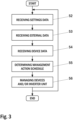
- FIG. 3 illustrates a flow diagram of an embodiment of a method for energy management of electric devices in an arrangement comprising electric devices and an energy management unit according to the present invention.
- settings data is first received 52 by said energy management unit 10, said settings data comprising the preset energy demand levels of said electric devices 101-103, 109.
- external data is received 53 by said energy management unit 10, said external data comprising the current and upcoming spot-price of electricity.
- device data from said electric devices 101-103, 109 and/or from said inverter unit 30 is received 54 by said energy management unit 10, said device data comprising status data and/or measurement data of said electric devices 101-103, 109 and/or of said inverter unit 30 and/or of said photovoltaic system 35 and/or of said battery unit 36.
- management action schedule is determined based on said settings data and on said external data and on said device data.
- said electric devices 101-103, 109 and/or said inverter unit 30 are managed 56 by said energy management unit 10 utilising said management action schedule.
- said inverter unit 30 may control said photovoltaic system 35 and said battery unit 36 utilising said management action schedule.
- FIG. 4 illustrates a flow diagram of another embodiment of a method for energy management of electric devices in an arrangement comprising electric devices and an energy management unit according to the present invention.
- the user provides to said energy management unit 10 user control data for controlling said energy management unit 10.
- user control data is first received 51 by said energy management unit 10, said user control data comprising instructions for controlling said energy management unit 10.
- settings data is received 52 by said energy management unit 10, said settings data comprising the preset energy demand levels of said electric devices 101-103, 109.
- external data is received 53 by said energy management unit 10, said external data comprising the current and upcoming spot-price of electricity.
- device data from said electric devices 101-103, 109 and/or from said inverter unit 30 is received 54 by said energy management unit 10, said device data comprising status data and/or measurement data of said electric devices 101-103, 109 and/or of said inverter unit 30 and/or of said photovoltaic system 35 and/or of said battery unit 36.
- management action schedule is determined based on said settings data and on said external data and on said device data.
- said electric devices 101 - 103, 109 and/or said inverter unit 30 are managed 56 by said energy management unit 10 utilising said management action schedule.
- said inverter unit 30 may control said photovoltaic system 35 and said battery unit 36 utilising said management action schedule.
- the energy management unit 10 relates to the area of so called “green energy” and more precisely levelling out peaks in energy supply and demand.
- the energy management unit 10 according to the present invention is a cloud connected IoT device with the special feature of being aware of current and upcoming spot-price of electricity and thereby being able to control other devices in any kind of application specifically based on the spot-price information.
- the energy management unit 10 can for example be used in the area of "green energy” solar power plants with energy storage to automatically control the inverter to export stored energy to the grid when the demand is peaking or it can control the heating of a boiler to use electricity in place of oil when the supply of electricity is peaking helping to solve the problem of supply and demand peaks of electricity but also for example optimizing profits from a small scale solar power plant with energy storage.
- the energy management unit 10 may be a cloud-connected IoT device that can automatically control other devices using communication protocol or general purpose inputs and outputs and using the current and/or upcoming spot-price of electricity to decide what control commands to send or what general purpose outputs to set.
- the energy management unit 10 according to the present invention is aware of the current and upcoming spot-price of electricity and thereby aware of the current supply and demand level and upcoming peaks in supply and demand of energy.
- the invention finds the max spot price hour and decides that is an hour where it will control the Inverter in the solar power plant to fully feed to grid any stored and overproduced energy by writing to the inverters dedicated operation mode modbus register over ModbusTCP.
- it takes 2 hours to unload the stored energy from the batteries so it will also check which one of the hour above or below the "max hour” that have the higher price and decide that is also an hour where it will fully feed to grid.
- it will set preceding and following two hours as maximum self-consumption and charging battery hours and so on looping through all hours of the day so it will cycle the battery while the spot price is higher than the set limit.
- Always when the price is below set limit it will just wait and top-up the battery charge if the load has consumed the battery to below 80% so that it will be ready and charged when the demand of the electricity is again high.
- the invention knows that in a set number of hours the spot price on electricity will dip below the limit where it is more profitable to heat the boiler with electricity compared to heating it with oil.
- the invention sets an output that prevents the oil-heater from starting even if the thermostat is requesting it to start.
- the set number of hours e.g. two hours
- the invention will set another output that is activating the electrical heating of the boiler.
- the spot price has again climbed above the limit where the oil-heating is more profitable it will stop the electrical heating and release the bypass of the thermostat so that the oil-heater is again operating based on the control of the thermostat.
- the electric devices can be properly managed and controlled to use energy when energy supply is high.
- the solar power production sites can be managed to export their produced energy when the demand is high and use small scale battery storage to store the energy when the demand is low.
- the invention can be used to control other devices to use energy when energy supply is high.
- the problematic supply and demand peaks in the power grid is helped to in levelling out.
Landscapes
- Engineering & Computer Science (AREA)
- Power Engineering (AREA)
- Supply And Distribution Of Alternating Current (AREA)
Applications Claiming Priority (1)
| Application Number | Priority Date | Filing Date | Title |
|---|---|---|---|
| FI20227115 | 2022-08-26 |
Publications (2)
| Publication Number | Publication Date |
|---|---|
| EP4329129A2 true EP4329129A2 (de) | 2024-02-28 |
| EP4329129A3 EP4329129A3 (de) | 2024-04-10 |
Family
ID=87845559
Family Applications (1)
| Application Number | Title | Priority Date | Filing Date |
|---|---|---|---|
| EP23193506.5A Pending EP4329129A3 (de) | 2022-08-26 | 2023-08-25 | Energieverwaltungseinheit zur verwaltung elektrischer vorrichtungen und verfahren zur energieverwaltung elektrischer vorrichtungen |
Country Status (1)
| Country | Link |
|---|---|
| EP (1) | EP4329129A3 (de) |
Family Cites Families (5)
| Publication number | Priority date | Publication date | Assignee | Title |
|---|---|---|---|---|
| CA2531839A1 (en) * | 2005-01-10 | 2006-07-10 | Chun S. Tung | Systems, methods and devices for effective electric energy consumption |
| EP2011030A2 (de) * | 2006-03-24 | 2009-01-07 | Rtp Controls | Verfahren und vorrichtung zur energieverbrauchregelung |
| US9671843B2 (en) * | 2011-03-31 | 2017-06-06 | Energent Incorporated | Computer implemented electrical energy hub management system and method |
| AU2017265184A1 (en) * | 2017-04-19 | 2018-11-08 | Natural Solar Pty Ltd | Systems for supplying power to a grid |
| WO2019099963A1 (en) * | 2017-11-18 | 2019-05-23 | Christopher Dunbar | End user controlled load management system |
-
2023
- 2023-08-25 EP EP23193506.5A patent/EP4329129A3/de active Pending
Also Published As
| Publication number | Publication date |
|---|---|
| EP4329129A3 (de) | 2024-04-10 |
Similar Documents
| Publication | Publication Date | Title |
|---|---|---|
| US11042948B1 (en) | Computing component arrangement based on ramping capabilities | |
| US10658841B2 (en) | Clustered power generator architecture | |
| CN102055215B (zh) | 一种电动汽车充换电站控制方法和运行监控系统 | |
| JP6256844B2 (ja) | 電力管理装置、電力管理システム、電力管理方法 | |
| EP2722962B1 (de) | Ladesystem, ladeverwaltungsvorrichtung, steuerverfahren und programm dafür | |
| US20210339647A1 (en) | Managing the Charging of a Fleet of Vehicles to Align with a Renewable Energy Supply Curve for an Electric Grid | |
| US11563325B1 (en) | Methods and systems for automatic generation control of renewable energy resources | |
| CN113098066A (zh) | 一种功率调节方法、功率调节装置及终端设备 | |
| EP4329129A2 (de) | Energieverwaltungseinheit zur verwaltung elektrischer vorrichtungen und verfahren zur energieverwaltung elektrischer vorrichtungen | |
| CN116722524A (zh) | 一种户外电源及用于户外电源的电能分配方法 | |
| US20120068534A1 (en) | Power Supply System Including Alternative Sources-Control and Communication | |
| CN112366758B (zh) | 电网调频控制方法及装置 | |
| EP3920370A1 (de) | Energieverwaltungsvorrichtung, energiespeichervorrichtung und leistungsverwaltungsverfahren | |
| JP2019030123A (ja) | 電源管理方法、電源管理サーバ及び電源管理装置 | |
| JP2022191478A (ja) | 電力管理装置及び電力管理方法 | |
| US11876399B1 (en) | Systems and methods for offsetting no load energy losses of a battery energy storage system | |
| US20230029613A1 (en) | Power management system and power management method | |
| US20230049482A1 (en) | Power management system and power management method | |
| US11799297B1 (en) | Systems and methods for offsetting parasitic energy losses of a battery energy storage system | |
| US20230052914A1 (en) | Power management system and power management method | |
| CN101938123B (zh) | 利用型风光发电控制系统及控制方法 | |
| US11705727B2 (en) | Methods and systems for automatic generation control of renewable energy resources | |
| CN115940277B (zh) | 能量调度方法、装置、电子设备及可读存储介质 | |
| EP4084278A1 (de) | Stromverwaltungssystem und stromverwaltungsverfahren | |
| JP2023003860A (ja) | 電力管理装置及び電力管理方法 |
Legal Events
| Date | Code | Title | Description |
|---|---|---|---|
| PUAI | Public reference made under article 153(3) epc to a published international application that has entered the european phase |
Free format text: ORIGINAL CODE: 0009012 |
|
| STAA | Information on the status of an ep patent application or granted ep patent |
Free format text: STATUS: THE APPLICATION HAS BEEN PUBLISHED |
|
| AK | Designated contracting states |
Kind code of ref document: A2 Designated state(s): AL AT BE BG CH CY CZ DE DK EE ES FI FR GB GR HR HU IE IS IT LI LT LU LV MC ME MK MT NL NO PL PT RO RS SE SI SK SM TR |
|
| PUAL | Search report despatched |
Free format text: ORIGINAL CODE: 0009013 |
|
| AK | Designated contracting states |
Kind code of ref document: A3 Designated state(s): AL AT BE BG CH CY CZ DE DK EE ES FI FR GB GR HR HU IE IS IT LI LT LU LV MC ME MK MT NL NO PL PT RO RS SE SI SK SM TR |
|
| RIC1 | Information provided on ipc code assigned before grant |
Ipc: H02J 13/00 20060101ALI20240304BHEP Ipc: H02J 3/14 20060101AFI20240304BHEP |