EP4329021A1 - Separator and method for producing same - Google Patents
Separator and method for producing same Download PDFInfo
- Publication number
- EP4329021A1 EP4329021A1 EP21950913.0A EP21950913A EP4329021A1 EP 4329021 A1 EP4329021 A1 EP 4329021A1 EP 21950913 A EP21950913 A EP 21950913A EP 4329021 A1 EP4329021 A1 EP 4329021A1
- Authority
- EP
- European Patent Office
- Prior art keywords
- mass
- parts
- separator
- plate
- resin
- Prior art date
- Legal status (The legal status is an assumption and is not a legal conclusion. Google has not performed a legal analysis and makes no representation as to the accuracy of the status listed.)
- Pending
Links
- 238000004519 manufacturing process Methods 0.000 title claims abstract description 25
- 239000000835 fiber Substances 0.000 claims abstract description 125
- 229920005989 resin Polymers 0.000 claims abstract description 72
- 239000011347 resin Substances 0.000 claims abstract description 72
- 125000001989 1,3-phenylene group Chemical group [H]C1=C([H])C([*:1])=C([H])C([*:2])=C1[H] 0.000 claims abstract description 62
- OKTJSMMVPCPJKN-UHFFFAOYSA-N Carbon Chemical compound [C] OKTJSMMVPCPJKN-UHFFFAOYSA-N 0.000 claims abstract description 62
- 229920003235 aromatic polyamide Polymers 0.000 claims abstract description 62
- 229910002804 graphite Inorganic materials 0.000 claims abstract description 58
- 239000010439 graphite Substances 0.000 claims abstract description 58
- 229920006231 aramid fiber Polymers 0.000 claims abstract description 44
- 230000005611 electricity Effects 0.000 claims abstract description 7
- 238000003860 storage Methods 0.000 claims abstract description 7
- 238000007493 shaping process Methods 0.000 claims description 94
- 239000000463 material Substances 0.000 claims description 73
- 230000004888 barrier function Effects 0.000 claims description 66
- 239000002245 particle Substances 0.000 claims description 42
- 239000004734 Polyphenylene sulfide Substances 0.000 claims description 40
- 238000000034 method Methods 0.000 claims description 40
- 229920000069 polyphenylene sulfide Polymers 0.000 claims description 40
- 239000000203 mixture Substances 0.000 claims description 37
- 239000002243 precursor Substances 0.000 claims description 30
- 239000000843 powder Substances 0.000 claims description 16
- 238000002156 mixing Methods 0.000 claims description 10
- 239000004696 Poly ether ether ketone Substances 0.000 claims description 7
- 229920002530 polyetherether ketone Polymers 0.000 claims description 7
- 229920005992 thermoplastic resin Polymers 0.000 claims description 7
- 229920001494 Technora Polymers 0.000 description 24
- 239000004950 technora Substances 0.000 description 24
- 238000005452 bending Methods 0.000 description 23
- 239000000470 constituent Substances 0.000 description 21
- 229920000049 Carbon (fiber) Polymers 0.000 description 19
- 239000004917 carbon fiber Substances 0.000 description 19
- 239000000446 fuel Substances 0.000 description 18
- VNWKTOKETHGBQD-UHFFFAOYSA-N methane Chemical compound C VNWKTOKETHGBQD-UHFFFAOYSA-N 0.000 description 16
- 229910021383 artificial graphite Inorganic materials 0.000 description 15
- 239000007789 gas Substances 0.000 description 15
- 229920000561 Twaron Polymers 0.000 description 13
- 239000004762 twaron Substances 0.000 description 13
- 238000011156 evaluation Methods 0.000 description 12
- UFHFLCQGNIYNRP-UHFFFAOYSA-N Hydrogen Chemical compound [H][H] UFHFLCQGNIYNRP-UHFFFAOYSA-N 0.000 description 11
- 239000007769 metal material Substances 0.000 description 8
- 239000003575 carbonaceous material Substances 0.000 description 7
- 238000007254 oxidation reaction Methods 0.000 description 7
- 239000001257 hydrogen Substances 0.000 description 6
- 229910052739 hydrogen Inorganic materials 0.000 description 6
- XLYOFNOQVPJJNP-UHFFFAOYSA-N water Substances O XLYOFNOQVPJJNP-UHFFFAOYSA-N 0.000 description 6
- QVGXLLKOCUKJST-UHFFFAOYSA-N atomic oxygen Chemical compound [O] QVGXLLKOCUKJST-UHFFFAOYSA-N 0.000 description 5
- 238000012986 modification Methods 0.000 description 5
- 230000004048 modification Effects 0.000 description 5
- 239000001301 oxygen Substances 0.000 description 5
- 229910052760 oxygen Inorganic materials 0.000 description 5
- 229920006269 PPS film Polymers 0.000 description 4
- 239000003990 capacitor Substances 0.000 description 4
- 238000005260 corrosion Methods 0.000 description 4
- 230000007797 corrosion Effects 0.000 description 4
- 238000010298 pulverizing process Methods 0.000 description 4
- 239000004760 aramid Substances 0.000 description 3
- 238000006243 chemical reaction Methods 0.000 description 3
- 238000009826 distribution Methods 0.000 description 3
- 230000000694 effects Effects 0.000 description 3
- -1 ether ketone ketone Chemical class 0.000 description 3
- 229920000642 polymer Polymers 0.000 description 3
- 239000000126 substance Substances 0.000 description 3
- 229920000106 Liquid crystal polymer Polymers 0.000 description 2
- 239000004977 Liquid-crystal polymers (LCPs) Substances 0.000 description 2
- WHXSMMKQMYFTQS-UHFFFAOYSA-N Lithium Chemical compound [Li] WHXSMMKQMYFTQS-UHFFFAOYSA-N 0.000 description 2
- 239000004952 Polyamide Substances 0.000 description 2
- 239000004697 Polyetherimide Substances 0.000 description 2
- 239000004642 Polyimide Substances 0.000 description 2
- 229920000491 Polyphenylsulfone Polymers 0.000 description 2
- 229920013629 Torelina Polymers 0.000 description 2
- 239000004742 Torelina™ Substances 0.000 description 2
- 235000010724 Wisteria floribunda Nutrition 0.000 description 2
- MCMNRKCIXSYSNV-UHFFFAOYSA-N Zirconium dioxide Chemical compound O=[Zr]=O MCMNRKCIXSYSNV-UHFFFAOYSA-N 0.000 description 2
- 229910045601 alloy Inorganic materials 0.000 description 2
- 239000000956 alloy Substances 0.000 description 2
- 230000008901 benefit Effects 0.000 description 2
- 239000000498 cooling water Substances 0.000 description 2
- 230000005484 gravity Effects 0.000 description 2
- 230000002687 intercalation Effects 0.000 description 2
- 238000009830 intercalation Methods 0.000 description 2
- 229910052744 lithium Inorganic materials 0.000 description 2
- 239000012528 membrane Substances 0.000 description 2
- 229910021382 natural graphite Inorganic materials 0.000 description 2
- 229920002493 poly(chlorotrifluoroethylene) Polymers 0.000 description 2
- 229920002492 poly(sulfone) Polymers 0.000 description 2
- 229920002647 polyamide Polymers 0.000 description 2
- 239000005023 polychlorotrifluoroethylene (PCTFE) polymer Substances 0.000 description 2
- 229920001601 polyetherimide Polymers 0.000 description 2
- 229920001721 polyimide Polymers 0.000 description 2
- 229920001343 polytetrafluoroethylene Polymers 0.000 description 2
- 239000004810 polytetrafluoroethylene Substances 0.000 description 2
- 239000002002 slurry Substances 0.000 description 2
- 239000007787 solid Substances 0.000 description 2
- QAOWNCQODCNURD-UHFFFAOYSA-N sulfuric acid Substances OS(O)(=O)=O QAOWNCQODCNURD-UHFFFAOYSA-N 0.000 description 2
- 238000012360 testing method Methods 0.000 description 2
- 238000012546 transfer Methods 0.000 description 2
- VGGSQFUCUMXWEO-UHFFFAOYSA-N Ethene Chemical compound C=C VGGSQFUCUMXWEO-UHFFFAOYSA-N 0.000 description 1
- 239000005977 Ethylene Substances 0.000 description 1
- 229910000760 Hardened steel Inorganic materials 0.000 description 1
- 229920008285 Poly(ether ketone) PEK Polymers 0.000 description 1
- 229920012266 Poly(ether sulfone) PES Polymers 0.000 description 1
- RTAQQCXQSZGOHL-UHFFFAOYSA-N Titanium Chemical compound [Ti] RTAQQCXQSZGOHL-UHFFFAOYSA-N 0.000 description 1
- 238000010521 absorption reaction Methods 0.000 description 1
- 229910052782 aluminium Inorganic materials 0.000 description 1
- XAGFODPZIPBFFR-UHFFFAOYSA-N aluminium Chemical compound [Al] XAGFODPZIPBFFR-UHFFFAOYSA-N 0.000 description 1
- 229910003481 amorphous carbon Inorganic materials 0.000 description 1
- 239000011230 binding agent Substances 0.000 description 1
- 239000000919 ceramic Substances 0.000 description 1
- 238000004891 communication Methods 0.000 description 1
- 150000001875 compounds Chemical class 0.000 description 1
- 229920001577 copolymer Polymers 0.000 description 1
- 238000007599 discharging Methods 0.000 description 1
- 238000001035 drying Methods 0.000 description 1
- 239000003792 electrolyte Substances 0.000 description 1
- RTZKZFJDLAIYFH-UHFFFAOYSA-N ether Substances CCOCC RTZKZFJDLAIYFH-UHFFFAOYSA-N 0.000 description 1
- 229920000840 ethylene tetrafluoroethylene copolymer Polymers 0.000 description 1
- 230000002349 favourable effect Effects 0.000 description 1
- 238000007710 freezing Methods 0.000 description 1
- 230000008014 freezing Effects 0.000 description 1
- 239000003014 ion exchange membrane Substances 0.000 description 1
- 239000002075 main ingredient Substances 0.000 description 1
- 229910052751 metal Inorganic materials 0.000 description 1
- 239000002184 metal Substances 0.000 description 1
- 230000003287 optical effect Effects 0.000 description 1
- 238000005192 partition Methods 0.000 description 1
- 230000000149 penetrating effect Effects 0.000 description 1
- 229920002120 photoresistant polymer Polymers 0.000 description 1
- 238000007747 plating Methods 0.000 description 1
- 229920001643 poly(ether ketone) Polymers 0.000 description 1
- 229920002312 polyamide-imide Polymers 0.000 description 1
- 238000006116 polymerization reaction Methods 0.000 description 1
- 239000010970 precious metal Substances 0.000 description 1
- 230000008569 process Effects 0.000 description 1
- 238000004544 sputter deposition Methods 0.000 description 1
- 239000010935 stainless steel Substances 0.000 description 1
- 229910001220 stainless steel Inorganic materials 0.000 description 1
- 238000005728 strengthening Methods 0.000 description 1
- BFKJFAAPBSQJPD-UHFFFAOYSA-N tetrafluoroethene Chemical group FC(F)=C(F)F BFKJFAAPBSQJPD-UHFFFAOYSA-N 0.000 description 1
- 239000010936 titanium Substances 0.000 description 1
- 229910052719 titanium Inorganic materials 0.000 description 1
- 238000009966 trimming Methods 0.000 description 1
Images






Classifications
-
- H—ELECTRICITY
- H01—ELECTRIC ELEMENTS
- H01M—PROCESSES OR MEANS, e.g. BATTERIES, FOR THE DIRECT CONVERSION OF CHEMICAL ENERGY INTO ELECTRICAL ENERGY
- H01M8/00—Fuel cells; Manufacture thereof
- H01M8/02—Details
- H01M8/0202—Collectors; Separators, e.g. bipolar separators; Interconnectors
- H01M8/0204—Non-porous and characterised by the material
- H01M8/0213—Gas-impermeable carbon-containing materials
-
- H—ELECTRICITY
- H01—ELECTRIC ELEMENTS
- H01M—PROCESSES OR MEANS, e.g. BATTERIES, FOR THE DIRECT CONVERSION OF CHEMICAL ENERGY INTO ELECTRICAL ENERGY
- H01M50/00—Constructional details or processes of manufacture of the non-active parts of electrochemical cells other than fuel cells, e.g. hybrid cells
- H01M50/40—Separators; Membranes; Diaphragms; Spacing elements inside cells
- H01M50/403—Manufacturing processes of separators, membranes or diaphragms
-
- H—ELECTRICITY
- H01—ELECTRIC ELEMENTS
- H01M—PROCESSES OR MEANS, e.g. BATTERIES, FOR THE DIRECT CONVERSION OF CHEMICAL ENERGY INTO ELECTRICAL ENERGY
- H01M50/00—Constructional details or processes of manufacture of the non-active parts of electrochemical cells other than fuel cells, e.g. hybrid cells
- H01M50/40—Separators; Membranes; Diaphragms; Spacing elements inside cells
- H01M50/409—Separators, membranes or diaphragms characterised by the material
- H01M50/411—Organic material
- H01M50/414—Synthetic resins, e.g. thermoplastics or thermosetting resins
-
- H—ELECTRICITY
- H01—ELECTRIC ELEMENTS
- H01M—PROCESSES OR MEANS, e.g. BATTERIES, FOR THE DIRECT CONVERSION OF CHEMICAL ENERGY INTO ELECTRICAL ENERGY
- H01M50/00—Constructional details or processes of manufacture of the non-active parts of electrochemical cells other than fuel cells, e.g. hybrid cells
- H01M50/40—Separators; Membranes; Diaphragms; Spacing elements inside cells
- H01M50/409—Separators, membranes or diaphragms characterised by the material
- H01M50/411—Organic material
- H01M50/414—Synthetic resins, e.g. thermoplastics or thermosetting resins
- H01M50/423—Polyamide resins
-
- H—ELECTRICITY
- H01—ELECTRIC ELEMENTS
- H01M—PROCESSES OR MEANS, e.g. BATTERIES, FOR THE DIRECT CONVERSION OF CHEMICAL ENERGY INTO ELECTRICAL ENERGY
- H01M50/00—Constructional details or processes of manufacture of the non-active parts of electrochemical cells other than fuel cells, e.g. hybrid cells
- H01M50/40—Separators; Membranes; Diaphragms; Spacing elements inside cells
- H01M50/409—Separators, membranes or diaphragms characterised by the material
- H01M50/449—Separators, membranes or diaphragms characterised by the material having a layered structure
-
- H—ELECTRICITY
- H01—ELECTRIC ELEMENTS
- H01M—PROCESSES OR MEANS, e.g. BATTERIES, FOR THE DIRECT CONVERSION OF CHEMICAL ENERGY INTO ELECTRICAL ENERGY
- H01M8/00—Fuel cells; Manufacture thereof
- H01M8/02—Details
- H01M8/0202—Collectors; Separators, e.g. bipolar separators; Interconnectors
- H01M8/0204—Non-porous and characterised by the material
- H01M8/0221—Organic resins; Organic polymers
-
- H—ELECTRICITY
- H01—ELECTRIC ELEMENTS
- H01M—PROCESSES OR MEANS, e.g. BATTERIES, FOR THE DIRECT CONVERSION OF CHEMICAL ENERGY INTO ELECTRICAL ENERGY
- H01M8/00—Fuel cells; Manufacture thereof
- H01M8/02—Details
- H01M8/0202—Collectors; Separators, e.g. bipolar separators; Interconnectors
- H01M8/0204—Non-porous and characterised by the material
- H01M8/0223—Composites
- H01M8/0226—Composites in the form of mixtures
-
- H—ELECTRICITY
- H01—ELECTRIC ELEMENTS
- H01M—PROCESSES OR MEANS, e.g. BATTERIES, FOR THE DIRECT CONVERSION OF CHEMICAL ENERGY INTO ELECTRICAL ENERGY
- H01M8/00—Fuel cells; Manufacture thereof
- H01M8/02—Details
- H01M8/0202—Collectors; Separators, e.g. bipolar separators; Interconnectors
- H01M8/0204—Non-porous and characterised by the material
- H01M8/0223—Composites
- H01M8/0228—Composites in the form of layered or coated products
-
- H—ELECTRICITY
- H01—ELECTRIC ELEMENTS
- H01M—PROCESSES OR MEANS, e.g. BATTERIES, FOR THE DIRECT CONVERSION OF CHEMICAL ENERGY INTO ELECTRICAL ENERGY
- H01M8/00—Fuel cells; Manufacture thereof
- H01M8/02—Details
- H01M8/0202—Collectors; Separators, e.g. bipolar separators; Interconnectors
- H01M8/0258—Collectors; Separators, e.g. bipolar separators; Interconnectors characterised by the configuration of channels, e.g. by the flow field of the reactant or coolant
- H01M8/026—Collectors; Separators, e.g. bipolar separators; Interconnectors characterised by the configuration of channels, e.g. by the flow field of the reactant or coolant characterised by grooves, e.g. their pitch or depth
-
- H—ELECTRICITY
- H01—ELECTRIC ELEMENTS
- H01M—PROCESSES OR MEANS, e.g. BATTERIES, FOR THE DIRECT CONVERSION OF CHEMICAL ENERGY INTO ELECTRICAL ENERGY
- H01M8/00—Fuel cells; Manufacture thereof
- H01M8/10—Fuel cells with solid electrolytes
- H01M2008/1095—Fuel cells with polymeric electrolytes
-
- H—ELECTRICITY
- H01—ELECTRIC ELEMENTS
- H01M—PROCESSES OR MEANS, e.g. BATTERIES, FOR THE DIRECT CONVERSION OF CHEMICAL ENERGY INTO ELECTRICAL ENERGY
- H01M8/00—Fuel cells; Manufacture thereof
- H01M8/18—Regenerative fuel cells, e.g. redox flow batteries or secondary fuel cells
- H01M8/184—Regeneration by electrochemical means
- H01M8/188—Regeneration by electrochemical means by recharging of redox couples containing fluids; Redox flow type batteries
-
- Y—GENERAL TAGGING OF NEW TECHNOLOGICAL DEVELOPMENTS; GENERAL TAGGING OF CROSS-SECTIONAL TECHNOLOGIES SPANNING OVER SEVERAL SECTIONS OF THE IPC; TECHNICAL SUBJECTS COVERED BY FORMER USPC CROSS-REFERENCE ART COLLECTIONS [XRACs] AND DIGESTS
- Y02—TECHNOLOGIES OR APPLICATIONS FOR MITIGATION OR ADAPTATION AGAINST CLIMATE CHANGE
- Y02E—REDUCTION OF GREENHOUSE GAS [GHG] EMISSIONS, RELATED TO ENERGY GENERATION, TRANSMISSION OR DISTRIBUTION
- Y02E60/00—Enabling technologies; Technologies with a potential or indirect contribution to GHG emissions mitigation
- Y02E60/10—Energy storage using batteries
-
- Y—GENERAL TAGGING OF NEW TECHNOLOGICAL DEVELOPMENTS; GENERAL TAGGING OF CROSS-SECTIONAL TECHNOLOGIES SPANNING OVER SEVERAL SECTIONS OF THE IPC; TECHNICAL SUBJECTS COVERED BY FORMER USPC CROSS-REFERENCE ART COLLECTIONS [XRACs] AND DIGESTS
- Y02—TECHNOLOGIES OR APPLICATIONS FOR MITIGATION OR ADAPTATION AGAINST CLIMATE CHANGE
- Y02E—REDUCTION OF GREENHOUSE GAS [GHG] EMISSIONS, RELATED TO ENERGY GENERATION, TRANSMISSION OR DISTRIBUTION
- Y02E60/00—Enabling technologies; Technologies with a potential or indirect contribution to GHG emissions mitigation
- Y02E60/30—Hydrogen technology
- Y02E60/50—Fuel cells
-
- Y—GENERAL TAGGING OF NEW TECHNOLOGICAL DEVELOPMENTS; GENERAL TAGGING OF CROSS-SECTIONAL TECHNOLOGIES SPANNING OVER SEVERAL SECTIONS OF THE IPC; TECHNICAL SUBJECTS COVERED BY FORMER USPC CROSS-REFERENCE ART COLLECTIONS [XRACs] AND DIGESTS
- Y02—TECHNOLOGIES OR APPLICATIONS FOR MITIGATION OR ADAPTATION AGAINST CLIMATE CHANGE
- Y02P—CLIMATE CHANGE MITIGATION TECHNOLOGIES IN THE PRODUCTION OR PROCESSING OF GOODS
- Y02P70/00—Climate change mitigation technologies in the production process for final industrial or consumer products
- Y02P70/50—Manufacturing or production processes characterised by the final manufactured product
Definitions
- the present invention is related to a separator and a method for producing the same.
- Fuel cells are cells from which energy is taken out by using a reaction between hydrogen and oxygen. Because what is generated from the reaction is water, fuel cells are known to be earth environment-friendly cells. In particular, for the capability of achieving high power density while being compact and lightweight, solid polymer fuel cells are considered as a favorable candidate for batteries of automobiles, communication devices, electronic devices and the like, while the actual implementation thereof is also partially underway.
- a fuel cell is a cell stack in which a plurality of cells is stacked together. Wall members called separators are arranged between the cells. Each separator is a partition for separating paths for hydrogen and oxygen positioned adjacent to each other and plays a role in making the hydrogen and the oxygen flow while being in uniform contact with the entire surface of an ion exchange membrane. For this reason, grooves serving as flow paths are formed on the separators.
- separators can roughly be divided into a metal material group and a carbon material group.
- the material used for separators in the metal material group may be generally stainless steel, aluminum or an alloy thereof, or titanium or an alloy thereof.
- the separators in the metal material group have excellent processability and can be very thin, due to strength and ductility specific to metal.
- the separators in the metal material group have higher specific gravity than separators in the carbon material group (explained later) and thus contradict the idea of making fuel cells lightweight.
- the separators in the metal material group have disadvantages where corrosion resistance is low, and a passive film may be formed by some of the materials.
- the separators in the carbon material group have advantages where specific gravity is lower while corrosion resistance is higher, in comparison to the separators in the metal material group.
- the separators in the carbon material group are inferior in processability and mechanical strength.
- electrical resistance even lower (i.e., making electrical conductivity even higher).
- a separator is known, for example, in which graphite particles are dispersed in thermoplastic resin (see Patent Literature 2).
- the method of dispersing graphite particles in thermoplastic resin can realize high strength of separators to some extent. However, even when the separators in the carbon material group are produced in this manner, those separators are difficult to be made thinner and are required to have even higher strength. In addition, there is also a demand for excelling in having higher electrical conductivity.
- the foregoing may be applicable not only to separators of a fuel cell or fuel cells, but also to separators used in primary batteries such as lithium batteries, secondary batteries such as redox flow batteries, and other electricity storage devices such as capacitors.
- the present invention is able to provide the separator having excellent strength and electrical conductivity and the method for producing the same.
- Figure 1 presents a plan view of a separator according to a first embodiment of the present invention.
- Figure 2A presents a cross-sectional view of the separator in Figure 1 at A-A and an enlarged view of B which is a part thereof.
- Figure 2B presents enlarged views of variations a, b, and c of C which is a part of B being a part of Figure 2A .
- a separator 1 according to the present embodiment is a plate-like body having a substantially rectangular shape in a planar view.
- the separator 1 according to the present embodiment is the plate-like body that may sandwich, from both sides, a Membrane Electrode Assembly (MEA) in which an electrolyte membrane is interposed between an air electrode and a hydrogen electrode positioned on the two surfaces thereof.
- MEA Membrane Electrode Assembly
- the separator 1 is interpreted in a broader sense including an anode-side separator provided on the hydrogen electrode (which may be called “anode electrode”) side and a cathode-side separator provided on the air-electrode (which may be called “cathode electrode”) side.
- the separator 1 is a separator in the carbon material group. Further, the separator 1 is not limited to be used in a fuel cell or fuel cells, but may be used as a plate-like member disposed between cells in a redox flow battery or an electricity storage device of other types such as a capacitor.
- the separator 1 comprises through holes 11, 12, 21, and 22 penetrating in the thickness direction thereof.
- the through holes 11 and 21 are positioned on one end side of the separator 1.
- the through hole 12 is positioned on the other end side opposite the one end side of the separator 1, while being positioned opposite the through hole 21 in a planar view of the separator 1.
- the through hole 22 is positioned on the other end side opposite the one end side of the separator 1, while being positioned opposite the through hole 11 in a planar view of the separator 1.
- a surface 31 other than the grooves 30 is formed as a raised plane in contrast to the grooves 30.
- grooves 32 serving as flow paths are formed on the other surface (a rear surface) on the opposite side of the one surface of the separator 1.
- a surface 31 other than the grooves 32 is formed as a raised plane in contrast to the grooves 32.
- the through hole 11 serves as an oxidization gas supply opening.
- the through hole 12 serves as an oxidization gas discharge opening.
- the through hole 21 serves as a hydrogen gas discharge opening.
- the through hole 22 serves as a hydrogen gas supply opening.
- the oxidization gas may be air, for example, but may be oxygen.
- the grooves 30 on the front surface of the separator 1 serve as flow paths in which the oxidization gas flows.
- the grooves 32 on the rear surface of the separator 1 serve as flow paths in which cooling water flows.
- the white arrows indicate flows of the oxidization gas.
- the through hole 11 serves as a hydrogen gas supply opening.
- the through hole 12 serves as a hydrogen gas discharge opening.
- the through hole 21 serves as an oxidization gas discharge opening.
- the through hole 22 serves as an oxidization gas supply opening.
- the grooves 30 on the front surface of the separator 1 serve as flow paths in which the hydrogen gas flows.
- the grooves 32 on the rear surface of the separator 1 serve as flow paths in which cooling water flows.
- the separator 1 comprises at least a plate 2.
- the separator 1 preferably comprises the plate 2 and, as an option, barrier layers 3 provided on the surfaces on both sides, in the thickness direction, of the plate 2.
- the plate 2 is a plate that contains graphite, resin, and aramid fiber different from the resin and comprises, on the surfaces thereof, the grooves 30 and 32 serving as the flow paths.
- the plate 2 is a shaped body containing the graphite, the resin, and the aramid fiber different from the resin and has a fine structure in which the graphite is dispersed in the resin that was melted and subsequently solidified.
- the graphite structuring the plate 2 is preferably in a particulate form or a fiber form.
- the resin structuring the plate 2 is preferably in a particulate form or a fiber form. In these situations, examples of the particulate form include a flake form (which may be called flakes).
- the fiber form examples include a whisker-like form.
- a more preferable combination of forms of the graphite, the resin, and the aramid fiber before being shaped is the graphite in a particulate or fiber form combined with the resin in a flake form and the aramid fiber in a fiber form.
- the plate 2 may contain one or more other types of fibers different from the resin and the aramid fiber. As long as the fiber is of a type different from the resin and the aramid fiber, the fiber may be any type of fiber such as resin fiber, carbon fiber, ceramic fiber, and/or the like.
- the plate 2 comprises grooves corresponding to the grooves 30 and 32 of the separator 1.
- the area of the plate 2 is preferably in the range of 10 cm 2 to 1000 cm 2 inclusive and more preferably in the range of 100 cm 2 to 750 cm 2 inclusive.
- the thickness of the plate 2 is preferably in the range of 0.1 mm to 20 mm inclusive and more preferably in the range of 0.2 mm to 10 mm inclusive.
- the resin structuring the plate 2 is not particularly limited, but is preferably thermoplastic resin. Resin having excellent heat resistance is more preferable for the resin to structure the plate 2. More specifically, examples include: polyphenylene sulfide (PPS), polyether ether ketone (PEEK), a polyamide (PA), polyether ketone ether ketone ketone (PEKEKK), polyether ketone (PEK), a liquid crystal polymer (LCP), polytetrafluoroethylene (PTFE), a copolymer of tetrafluoroethylene and ethylene (ETFE), polychlorotrifluoroethylene (PCTFE), polyimide (PI), a polyamide-imide (PAI), polyethersulfone (PES), polyphenylsulfone (PPSU), polyetherimide (PEI), and a polysulfone (PSU). Among these, PPS or PEEK is particularly preferable. Examples of PPS include M2888 and E2180 produced by Toray Industries, Inc
- the average particle diameter of the resin used before shaping the plate 2 is preferably in the range of 1 ⁇ m to 300 ⁇ m inclusive, more preferably in the range of 5 ⁇ m to 150 ⁇ m inclusive, and even more preferably in the range of 10 ⁇ m to 100 ⁇ m inclusive.
- the average particle diameter denotes a particle diameter measured by using a laser diffraction/scattering particle diameter distribution measuring method. The same applies to the method for measuring the average particle diameters hereinafter.
- the graphite structuring the plate 2 may be any of the following: artificial graphite, expanded graphite, natural graphite, and others.
- the expanded graphite denotes graphite or a graphite intercalation compound obtained by expanding the spaces between graphite layers by having a layer of another substance enter (called "intercalation") on a specific plane in a structure in which regular hexagonal planes of graphite are stacked together.
- BSP-60A having an average particle diameter of 60 ⁇ m
- EXP-50SM produced by Fuji Graphite Works Co., Ltd.
- the artificial graphite 1707SJ (average particle diameter: 125 ⁇ m), AT-No.
- the average particle diameter of the graphite used before shaping the plate 2 is preferably in the range of 1 ⁇ m to 500 ⁇ m inclusive, more preferably in the range of 3 ⁇ m to 300 ⁇ m inclusive, and even more preferably in the range of 10 ⁇ m to 150 ⁇ m inclusive.
- the particle diameters of the graphite and the resin may be adjusted separately before the two are mixed together to be used for shaping the plate 2.
- the graphite and the resin may be kneaded together at first, before being pulverized so that the particle diameters are adjusted for the use in shaping the plate 2.
- the average particle diameter of a powder mixture is preferably in the range of 1 ⁇ m to 500 ⁇ m inclusive, more preferably in the range of 3 ⁇ m to 300 ⁇ m inclusive, and even more preferably in the range of 10 ⁇ m to 150 ⁇ m inclusive.
- graphite:resin 70 to 95 parts by mass:30 to 5 parts by mass.
- by mixing 5 parts by mass of the resin with the graphite in an amount ranging from 70 parts by mass to 95 parts by mass inclusive it is possible to obtain a constituent material of the separator 1.
- by mixing 30 parts by mass of the resin with the graphite in an amount ranging from 70 parts by mass to 95 parts by mass inclusive it is also similarly possible to obtain a constituent material of the separator 1. It is preferable to configure the separator 1 to contain more graphite than resin by a mass ratio.
- a more preferable mass ratio between the graphite and the resin is achieved by mixing 1 part by mass of the resin, with 10 parts by mass of the graphite or with the graphite in an amount ranging from 10.1 parts by mass to 20 parts by mass inclusive.
- volume resistivity is 5 m ⁇ cm or lower.
- the aramid fiber being one of the constituent elements of the plate 2 is para-aramid fiber containing a meta-phenylene group expressed with Formula (1) presented below.
- m and n are positive numbers.
- the ratio m:n is preferably in the range of 5:1 to 1:9, and more preferably in the range of 4:1 to 1:4.
- the degree of polymerization of the aramid fiber is evaluated by using intrinsic viscosity ⁇ expressed with Expression (1) presented below.
- the value of ⁇ is preferably in the range of 1.5 to 7.0 inclusive and more preferably in the range of 2.0 to 5.0, inclusive.
- an Ostwald viscometer is used.
- Examples of the para-aramid fiber containing a meta-phenylene group include: Technora T320NW 1-12 (having an average fiber length of 1.0 mm and an average fiber diameter of 20 ⁇ m); Technora T32PNW 3-12 (having an average fiber length of 3.2 mm and an average fiber diameter of 18 ⁇ m); and Technora T320NW 6-12 (having an average fiber length of 6.0 mm and an average fiber diameter of 20 ⁇ m), which are produced by Teijin Limited.
- each of the average fiber lengths is an average value of the fiber lengths obtained by measuring 20 arbitrary fibers by using an optical microscope.
- Each of the average fiber diameters is an average value of the fiber diameters obtained by measuring 20 arbitrary fibers by using a scanning electron microscope. In this situation, when the end face of the fiber was not circular, the longest long side of the end face was regarded as the diameter of the fiber.
- the average fiber length of the para-aramid fiber containing the meta-phenylene group and used before shaping the plate 2 is preferably in the range of 0.5 mm to 8.0 mm inclusive, and more preferably in the range of 1 mm to 6 mm inclusive.
- the average fiber diameter of the para-aramid fiber containing the meta-phenylene group and used before shaping the plate 2 is preferably in the range of 2 ⁇ m to 50 ⁇ m inclusive, and more preferably in the range of 5 ⁇ m to 30 ⁇ m inclusive.
- the aramid fiber contained in the plate 2 because the aramid fiber has higher equilibrium water absorption than the base resin (e.g., PPS), hydrophilicity of the surface of the separator 1 is improved, which works effectively in discharging water along the surfaces of the separator 1 when water or water vapor occurred from a reaction between hydrogen and oxygen.
- having the aramid fiber contained is also effective in providing the base resin with heat resistance, strength, chemical resistance, and the like.
- the plate 2 contains the para-aramid fiber containing a meta-phenylene group, it is possible to improve bending strength and bending strain of the separator 1, while preventing electrical conductivity thereof from being degraded.
- para-aramid fiber containing a meta-phenylene group may be used.
- para-aramid fiber containing a meta-phenylene group and para-aramid fiber containing no meta-phenylene group may be used.
- para-aramid fiber containing no meta-phenylene group it is preferable when the content thereof is equal to or smaller than 10 mass % in relation to the mass of the para-aramid fiber containing a meta-phenylene group.
- the para-aramid fiber containing no meta-phenylene group is added in a small amount because there is an advantage where handling can be improved.
- Para-aramid fiber containing no meta-phenylene group has relatively smaller fiber diameters and does not achieve a strengthening effect by itself, but functions as a binder that puts the resin and the graphite together. For this reason, it is preferable to add the para-aramid fiber containing no meta-phenylene group in such an amount that electric properties will not be lost (equal to or smaller than 10 mass % in relation to the mass of the para-aramid fiber containing a meta-phenylene group), to prevent the resin and graphite particles from falling out of the precursor plate.
- a typical sample of the separator 1 comprising the plate 2 containing the para-aramid fiber that contains a meta-phenylene group has volume resistivity of 2.5 m ⁇ cm or smaller.
- the content of the aramid fiber (the para-aramid fiber containing a meta-phenylene group) in the plate 2 is in the range of 20 parts by mass to 230 parts by mass inclusive, in relation to 100 parts by mass of the resin (excluding the aramid fiber) structuring the plate 2.
- the barrier layers 3 in the present embodiment cover at least the surface on the front side and the surface on the rear side of the plate 2, including the grooves 30, 32 and the surfaces 31 of the plate 2 other than the grooves 30, 32.
- the barrier layers 3 cover both surfaces of the plate 2, namely the surface on the front side and the surface on the rear side, including the faces inside the grooves 30 and 32.
- the barrier layers 3 are, for example, each a film-like covering layer different from the plate 2 and are formed with two types of films that are separate from each other or fused together, namely, a first film 4 being an example of a barrier layer covering the surface on the front side and a second film 5 being an example of another barrier layer covering the surface on the rear side.
- the barrier layers 3 are separate as the first film 4 and the second film 5, which adhere to the surface on the front side and to the surface on the rear side of the plate 2, respectively.
- the barrier layers 3 may have a bag-like form in which the first film 4 and the second film 5 are joined together, to wrap the plate 2.
- Figure 2B presents enlarged views of variations a, b, and c of C which is a part of B being a part of Figure 2A .
- a barrier layer 3 is a film-like covering layer F different from the plate 2.
- a barrier layer 3 is provided so that the plate 2 is, in the vicinity of the surface thereof, impregnated with resin or rubber.
- the barrier layer 3 is a filling layer M in which the resin or the rubber fills the spaces between the particles or fibers structuring the plate 2.
- a barrier layer 3 includes a filling layer M and a covering layer F. As explained herein, the barrier layer 3 preferably use one of modes a, b, and c.
- the barrier layer 3 may use a mode other than modes a, b, and c.
- the "gas barrier property” or a “gas barrier capability” denotes a characteristic that prevents gas from passing through.
- the barrier layer 3 is preferably a layer of resin or rubber.
- one or two or more may be selected as principal material(s) from among the abovementioned preferable options for the resin to structure the plate 2, and more preferably, at least one of PEEK and PPS may be used as the principal material(s).
- the "principal material” denotes a material that accounts for more than 50 mass % of the barrier layer 3. As long as the principal material accounts for more than 50 mass % relative to the mass of the barrier layer 3, the percentage may be 51 mass %, 60 mass %, 70 mass %, 80 mass %, 90 mass %, 95 mass %, or 100 mass %, for example.
- the thickness of the barrier layer 3 is preferably in the range of 2 ⁇ m to 50 ⁇ m inclusive and more preferably in the range of 4 ⁇ m to 35 ⁇ m inclusive.
- the thickness of the barrier layer 3 is 2 ⁇ m or larger, or even 4 ⁇ m or larger, it is possible to further enhance the gas barrier property, to further enhance the strength (the bending strength), and to further enhance tractability of the separator 1.
- the thickness of the barrier layer 3 is 50 ⁇ m or smaller, or even 35 ⁇ m or smaller, it is possible to further lower the volume resistivity.
- the first film 4 and the second film 5 may have mutually the same thickness or mutually-different thicknesses.
- the strength denotes a bending strength measured according to JIS K 7171.
- the resin structuring the plate 2 and the resin structuring the barrier layer 3 may be the same type of thermoplastic resin. In that situation, because it is possible to integrally form the resin in the vicinity of the surface of the plate 2 with the barrier layer 3 covering the plate 2, it is possible to further increase the strength of the separator 1.
- the thermoplastic resin is, preferably, PEEK or PPS.
- the method for producing the separator 1 comprises: a shaping material arranging step of arranging, in a mold, a mixture (an example of the "shaping material") obtained by mixing together at least the graphite, the resin, and the aramid fiber (a constituent element different from the resin; the same applies hereinafter); and a shaping step of performing a shaping process by closing the mold while the shaping material is in the state of being arranged therein.
- the producing method of the separator 1 may preferably further comprise a first film arranging step, prior to the shaping material arranging step, of arranging the first film 4 in the mold; and a second film arranging step of arranging the second film 5 over the shaping material arranged in the mold in the shaping material arranging step.
- the separator producing method is preferably a method for producing a fuel cell separator used between cells in a fuel cell.
- the separator 1 is preferably a separator in the carbon material group.
- the separator 1 is not limited to be used in a fuel cell or fuel cells, and may be used as a plate-like member disposed between cells in a redox flow battery or an electricity storage device of other types such as a capacitor.
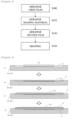
- Figure 3 shows an example of a flow in main steps in a separator producing method according to the first embodiment.
- Figure 4 presents cross-sectional views of statuses at the steps in the producing method in Figure 3 .
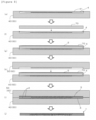
- Figure 5 presents cross-sectional views of statuses at the steps following Figure 4 .
- This step is a step of arranging, in a mold 60, the first film 4 for forming the barrier layer 3 on at least the surface on the rear side of the plate 2. More specifically, a bottom mold 40 structuring the mold 60 is prepared, and the first film 4 is placed in a recessed part 41 of the bottom mold 40 (see Figure 4 (a) and (b) ). On the inner bottom face of the recessed part 41, the bottom mold 40 comprises an uneven surface 42 capable of transferring and forming the grooves 32.
- This step is a step of supplying, to the inside of the mold 60, a mixture 2a containing the graphite, the resin, and the aramid fiber. More specifically, the mixture 2a is supplied to the top of the first film 4 placed in the bottom mold 40 (see Figure 4 (c) ).
- the mixture 2a contains at least the para-aramid fiber containing a meta-phenylene group mentioned above.
- This step is a step of arranging the second film 5 for forming the barrier layer 3 on at least the surface on the front side of the plate 2, over the mixture 2a arranged in the mold 60 in the shaping material arranging step (S110). More specifically, the second film 5 is placed over the mixture 2a arranged in the recessed part 41 of the bottom mold 40 (see Figure 4 (d) ).
- This step is a step of producing the shaped body by hardening the layered structure comprising the first film 4, the mixture 2a, and the second film 5. More specifically, a top mold 50 structuring the mold 60 is prepared and placed over the bottom mold 40 on the recessed part 41 side, and the bottom mold 40 and the top mold 50 are closed together (see Figure 5 (e) and (f) ).
- the top mold 50 has a recessed part 51 on the side facing the recessed part 41 of the bottom mold 40. On the inner bottom face thereof, the recessed part 51 comprises an uneven surface 52 capable of transferring and forming the grooves 30. After the mold 60 is clamped, the layered structure is shaped by applying heat thereto (see Figure 5 (g) ).
- the mixture 2a is hardened and forms the plate 2. Further, as a result of the transfer of the uneven surfaces 41 and 51, the grooves 30 and 32 in the state of being covered by the barrier layers 3 (the first film 4 and the second film 5) are formed (see Figure 5 (h) ).
- the mold 60 is opened, and the separator 1 is thus completed.
- one selected from between the first film arranging step (S100) and the second film arranging step (S120) may be omitted.
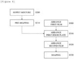
- Figure 6 shows an example of a flow in main steps in a producing method according to a second embodiment.
- Figure 7 presents cross-sectional views of statuses at the steps in the producing method in Figure 6 .
- Figure 8 presents cross-sectional views of statuses at the steps following Figure 7 .
- the producing method shown in Figure 6 is a method for producing the separator 1 by which a precursor plate is produced by semi-hardening the mixture 2a, and subsequently, the precursor plate is shaped as being sandwiched between the first film 4 and the second film 5.
- a pre-shaping step is performed to obtain the precursor plate in the semi-hardened state.
- the separator 1 It is possible to produce the separator 1 through a shaping material arranging step (S200), a pre-shaping step (S210), a first film arranging step (S300), a precursor plate arranging step (S310), a second film arranging step (S320), and a shaping step (S330).
- S200 through S210 and S300 through S330 will be explained in detail with reference to Figures 6 to 8 .
- This step is a step of supplying the mixture 2a containing the graphite, the resin, and the aramid fiber to the inside of a mold 65. More specifically, the mixture 2a is supplied to a recessed part 46 of a bottom mold 45 (see Figure 7 (a) ). As the aramid fiber, the mixture 2a contains at least the para-aramid fiber containing a meta-phenylene group mentioned above.
- This step is a step of producing the precursor plate by semi-hardening the mixture 2a. More specifically, a top mold 55 structuring the mold 65 is prepared and placed over the bottom mold 45 on the recessed part 46 side, and the bottom mold 45 and the top mold 55 are closed together (see Figure 7 (b), (c), and (d) ). The top mold 55 has a recessed part 56 on the side facing the recessed part 46 of the bottom mold 45. After the mold 65 is clamped, the mixture 2a is semi-hardened by applying heat thereto. The temperature at this time is lower than the temperature used in the shaping step. As a result, a precursor plate (the mixture in the semi-hardened state) 70 is completed.
- This step is a step of arranging the first film 4 in the mold 60 (see Figure 8 (e) ).
- the details are the same as the first film arranging step (S100) in the producing method according to the first embodiment.
- This step is a step of arranging the precursor plate 70 on the first film 4 placed in the recessed part 41 (see Figure 8 (f) ).
- This step is a step of arranging the second film 5 over the mixture 2a structuring the precursor plate 70 in the mold 60, after the precursor plate arranging step (S310) (see Figure 8 (g) ).
- This step is a step of producing the shaped body by hardening the layered structure comprising the first film 4, the precursor plate 70 (structured with the mixture 2a), and the second film 5. More specifically, the top mold 50 structuring the mold 60 is prepared and placed over the bottom mold 40 on the recessed part 41 side, and the bottom mold 40 and the top mold 50 are closed together (see Figure 8 (h) and (i) ). After the mold 60 is clamped, the layered structure is shaped by applying heat thereto. As a result, the mixture 2a is hardened and forms the plate 2. Further, as a result of the transfer of the uneven surfaces 41 and 51, the grooves 30 and 32 in the state of being covered by the barrier layers 3 (the first film 4 and the second film 5) are formed (see Figure 8 (j) ).
- the mold 60 is opened, and the separator 1 is thus completed.
- one selected from between the first film arranging step (S300) and the second film arranging step (S320) may be omitted.
- Figure 9 presents a cross-sectional view of a status when a grooved plate is used in place of the precursor plate, in a separator producing method according to a modification example.
- the bottom mold 45 and the top mold 55 each have an uneven surface formed on the inner bottom face thereof.
- a grooved plate 70a comprising pre-groove parts 71 and 72 that are shallower than the grooves 30 and 32 that serve as flow paths is produced.
- the grooved plate 70a is arranged on the first film 4, so that the pre-groove part 72 on the grooved plate 70a fits the uneven surface 42 (see Figure 9 ).
- the uneven surface 52 of the top mold 50 is fit to the pre-groove part 71 on the grooved plate 70a, so that the top mold 50 and the bottom mold 40 are closed together, and the mold 60 is thus clamped.
- the grooves 30 and 32 are formed by deepening the pre-groove parts 71 and 72 with the uneven surfaces 42 and 52, and the separator 1 is thus completed (see Figure 8 (i) and (j) ).
- the grooved plate 70a may have the grooves 30 and 32, in place of the pre-groove parts 71 and 72.
- the grooved plate 70a is arranged on the first film 4 so that the grooves 32 on the grooved plate 70a fit the uneven surface 42.
- the mold 60 is clamped so that the uneven surface 52 of the top mold 50 is fit to the grooves 30 on the grooved plate 70a.
- Figure 10 presents a cross-sectional view of a separator according to the second embodiment at A-A similar to Figure 2A and an enlarged view of B which is a part thereof.
- a separator 1a according to the present embodiment comprises the plate 2.
- the separator 1a according to the present embodiment does not comprise the barrier layers 3 (the first film 4 and the second film 5), unlike the separator 1 according to the first embodiment.
- the separator 1a is the same as the separator 1, except for not comprising the barrier layers 3.
- Figure 11 shows an example of a flow in main steps in a separator producing method according to the second embodiment.
- the method for producing of the separator 1a comprises: a shaping material arranging step (S400) of arranging, in a mold, a mixture (an example of the "shaping material") obtained by mixing together at least the graphite, the resin, and the aramid fiber; and a shaping step (S410) of performing a shaping process by closing the mold while the shaping material is in the state of being arranged therein.
- the shaping material arranging step (S400) corresponds to the shaping material arranging step (S110) except for being performed without arranging the first film 4 in the mold 60.
- the shaping step (S410) corresponds to the shaping step (S130) except for being performed without arranging the first film 4 and the second film 5. Accordingly, explanations that are duplicates of those about the producing method of the separator 1 according to the first embodiment above will be omitted.
- Figure 12 shows an example of a flow in main steps in a producing method different from Figure 11 .
- the separator 1a It is possible to produce the separator 1a through a shaping material arranging step (S500), a pre-shaping step (S510), a precursor plate arranging step (S600), and a shaping step (S610).
- the shaping material arranging step (S500) corresponds to the shaping material arranging step (S200).
- the pre-shaping step (S510) corresponds to the pre-shaping step (S210).
- the precursor plate arranging step (S600) corresponds to the precursor plate arranging step (S310) except for being performed without going through the first film arranging step (S300).
- the shaping step (S610) corresponds to the shaping step (S330) except for being performed without the first film 4 and the second film 5. Accordingly, explanations that are duplicates of those about the producing method of the separator 1 according to the first embodiment above will be omitted.
- the grooves 30 in the separator 1, 1a may be grooves forming flow paths other than the flow paths in which the gas flows in the directions shown with the white arrows in Figure 1 .
- the grooves 32 may be grooves forming flow paths in any form.
- the grooves 30 may be grooves forming linear flow paths extending from one end to the other end of the separator 1, while the grooves 32 may be grooves forming linear flow paths extending in a substantially perpendicular direction to the grooves 30.
- the separator 1, 1a may be formed without at least one of the grooves 30 and the grooves 32.
- a trimming step may be performed to trim an extra area of the first film 4 and/or the second film 5.
- the separator 1 comprises the barrier layers 3 on both surfaces, namely the surface on the front side and the surface on the rear side; however, the separator 1 may comprise a barrier layer 3 only one of the surfaces selected from between the surface on the front side and the surface on the rear side.
- the barrier layer 3 is formed only on the one of the surfaces, either the second film arranging step (S120, S320) or the first film arranging step (S100, S300) shall be omitted.
- the producing method in the first embodiment is a method for producing the fuel cell separator in which the barrier layer 3 is a layer of resin or rubber; however, the producing method may be a method for producing a fuel cell separator in which the barrier layer 3 is a layer in either mode "b" or mode "c" in Figure 2B .
- model number 1707SJ artificial graphite having an average particle diameter of 125 ⁇ m
- model number AT-No. 5S artificial graphite having an average particle diameter of 52 ⁇ m
- polyphenylene sulfide (PPS) powder As the resin serving as a constituent material of the plate of the separator, polyphenylene sulfide (PPS) powder was used. Used as the PPS was PPS fine powder adjusted to have an average particle diameter of 50 ⁇ m obtained by freezing and pulverizing PPS powder in a flake form of Torelina M2888 produced by Toray Industries, Inc.
- para-aramid fiber containing a meta-phenylene group As the aramid fiber serving as a constituent material of the plate of the separator, para-aramid fiber containing a meta-phenylene group, para-aramid fiber containing no meta-phenylene group, and meta-aramid fiber were used.
- the para-aramid fiber containing a meta-phenylene group the following three types of aramid fibers produced by Teijin Limited were used: Technora T320NW 1-12 (having an average fiber length of 1.0 mm and an average fiber diameter of 20 ⁇ m); Technora T32PNW 3-12 (having an average fiber length of 3.2 mm and an average fiber diameter of 18 ⁇ m); and Technora T320NW 6-12 (having an average fiber length of 6.0 mm and an average fiber diameter of 20 ⁇ m).
- Twaron 1080 having an average fiber length of 6.1 mm and an average fiber diameter of 24 ⁇ m
- Twaron 1094 having an average fiber length of 1.1 mm and a specific surface area of 13.6 m 2 /g
- Twaron 1097 having an average fiber length of 1.2 mm and a specific surface area of 6.9 m 2 /g
- Twaron D8016 having an average fiber length of 0.8 mm
- Conex C11-C having an average fiber length of 3.1 mm and an average fiber diameter of 21 ⁇ m
- PAN-based carbon fibers As other types of fibers serving as constituent materials of the plate of the separator, three types of fibers such as PAN-based carbon fibers, pitch-based carbon fiber, and PPS fiber were used.
- PAN-based carbon fibers the following two types of PAN-based carbon fibers produced by Teijin Limited were used: Tenax HT C110 (having an average fiber length of 7.3 mm and an average fiber diameter of 7 ⁇ m) and Tenax HT C137 (having an average fiber length of 6.0 mm and an average fiber diameter of 7 ⁇ m).
- GRANOC XN-100-03Z (having an average fiber length of 3.3 mm and an average fiber diameter of 11 ⁇ m) produced by Nippon Graphite Fiber Co., Ltd. was used.
- PPS fiber TORCON S307 (having an average fiber length of 6.0 mm and an average fiber diameter of 13 ⁇ m) produced by Toray Industries, Inc. was used.
- a film made of PPS was used as a film for the separator.
- a film made of PPS a film having a thickness of 9 ⁇ m (model number: Torelina 9-3071) produced by Toray Industries, Inc. was used.
- the volume resistivity of the separator was measured by using a device (Loresta-GX T-700) produced by Nittoseiko Analytech Co., Ltd., according to JIS K 7194. A volume resistivity value smaller than 2.5 m ⁇ cm was evaluated as a pass.
- a bending test for the separators was performed by using a device (Autograph AG-100kNG) produced by Shimadzu Corporation, according to JIS K 7171.
- a bending strength exceeding 40 MPa was evaluated as a pass.
- the slurry was input to a strainer comprising an input opening of a 25 cm square, to obtain a wet sheet, which was a sheet formed with residue from the straining.
- the wet sheet was set on a presser heated to 150°C and pressured and heated for approximately 20 minutes with surface pressure of 8 MPa. By drying the wet sheet and removing the moisture, a precursor plate having a thickness of 2 mm and an area-based weight of 2200 g/m 2 was produced in which the artificial graphite particles, the PPS particles, and the aramid fibers were dispersed.
- a PPS film having a thickness of 9 ⁇ m was placed in the recessed part inside the bottom mold structuring the separate-type mold, and the abovementioned precursor plate was supplied to the top of the film. After that, a PPS film having a thickness of 9 ⁇ m was placed over the precursor plate. Subsequently, a shaping process was performed by closing together the top mold and the bottom mold structuring the separate-type mold. The shaping process was performed by applying heat until the temperature of the mold reached 340°C with surface pressure of 4 MPa, and after the surface pressure was increased to 90 MPa, the workpiece was held for one minute. Subsequently, while keeping the pressure the same, the mold was cooled under pressure until the temperature reached 30°C. When the shaping process was finished, the mold was opened to take out the shaped body, and the production of a separator was thus finished. The separator was evaluated by using the abovementioned evaluation method.
- a separator was produced and evaluated under the same conditions as those in Example 1, except for adjusting the mixture by preparing the following: 1261.1 parts by mass of artificial graphite particles (model number: 1707SJ); 100 parts by mass of PPS powder; and 27.8 parts by mass of para-aramid fiber containing a meta-phenylene group (Technora T32PNW 3-12).
- a separator was produced and evaluated under the same conditions as those in Example 1, except for adjusting the mixture by preparing the following: 977.8 parts by mass of artificial graphite particles (model number: 1707SJ); 244.4 parts by mass of artificial graphite particles (model number: AT-No.5S); 100 parts by mass of PPS powder; and 66.7 parts by mass of para-aramid fiber containing a meta-phenylene group (Technora T32PNW 3-12).
- a separator was produced and evaluated under the same conditions as those in Example 1, except for adjusting the mixture by preparing the following: 1083.3 parts by mass of artificial graphite particles (model number: 1707SJ); 100 parts by mass of PPS powder; and 205.6 parts by mass of para-aramid fiber containing a meta-phenylene group (Technora T32PNW 3-12).
- a separator was produced and evaluated under the same conditions as those in Example 1, except for adjusting the mixture by preparing the following: 2308.3 parts by mass of artificial graphite particles (model number: AT-No.5S); 100 parts by mass of PPS powder; 111.1 parts by mass of para-aramid fiber containing a meta-phenylene group (Technora T32PNW 3-12); 8.3 parts by mass of para-aramid fiber containing no meta-phenylene group (Twaron 1094); and 250 parts by mass of pitch-based carbon fiber 250.
- a separator was produced and evaluated under the same conditions as those in Example 1, except for adjusting the mixture by preparing the following: 809.2 parts by mass of artificial graphite particles (model number: 1707SJ); 202.3 parts by mass of artificial graphite particles (model number: AT-No.5S); 100 parts by mass of PPS powder; 34.5 parts by mass of para-aramid fiber containing a meta-phenylene group (Technora T32PNW 3-12); and 3.4 parts by mass of para-aramid fiber containing no meta-phenylene group (Twaron D8016).
- a separator was produced and evaluated under the same conditions as those in Example 1, except for using 62.5 parts by mass of para-aramid fiber containing a meta-phenylene group (Technora T32PNW 3-12) in place of 62.5 parts by mass of the para-aramid fiber containing a meta-phenylene group (Technora T320NW 1-12).
- a separator was produced and evaluated under the same conditions as those in Example 1, except for using 62.5 parts by mass of para-aramid fiber containing a meta-phenylene group (Technora T320NW 6-12) and 4.2 parts by mass of para-aramid fiber containing no meta-phenylene group (Twaron 1094), in place of 62.5 parts by mass of the para-aramid fiber containing a meta-phenylene group (Technora T320NW 1-12) and 4.2 parts by mass of the para-aramid fiber containing no meta-phenylene group (Twaron D8016).
- Ball-mill pulverization using zirconia balls was performed on 1000 parts by mass of artificial graphite particles (model number: 1707SJ) and 100 parts by mass of PPS powder, to mix and pulverize the two types of powder.
- the ball-mill pulverization was ended when it was confirmed that the granularity of the powder mixture reached an average particle diameter of 90 ⁇ 10 ⁇ m by measuring the granularity distribution (through a measuring process implementing a laser diffraction/scattering particle diameter distribution measuring method).
- the shaping process was performed with surface pressure of 47 MPa, and the workpiece was held for three minutes so that the temperature of the mold increased up to 360°C.
- the mold was opened to take out the shaped body, and the production of the separator was thus finished.
- the separator was evaluated by using the abovementioned evaluation method.
- Tables 1 to 5 present the producing conditions of the Examples and the comparison examples, together with evaluation results.
- Table 1 MODEL NUMBER EXAMPLE 1 EXAMPLE 2 EXAMPLE 3 EXAMPLE 4 PPS M2888 100 PARTS BY MASS 100 PARTS BY MASS 100 PARTS BY MASS 100 PARTS BY MASS ARAMID FIBER T320NW 1-12 62.5 PARTS BY MASS 0 PARTS BY MASS 0 PARTS BY MASS 0 PARTS BY MASS T32PNW 3-12 0 PARTS BY MASS 27.8 PARTS BY MASS 66.7 PARTS BY MASS 205.6 PARTS BY MASS T320NW 6-12 0 PARTS BY MASS 0 PARTS BY MASS 0 PARTS BY MASS 1080 0 PARTS BY MASS 0 PARTS BY MASS 0 PARTS BY MASS 0 PARTS BY MASS 1080 0
- the separator according to the present invention is applicable to a fuel cell or fuel cells, primary batteries such as lithium batteries, secondary batteries such as redox flow batteries, and electricity storage devices such as capacitors.
Landscapes
- Chemical & Material Sciences (AREA)
- Chemical Kinetics & Catalysis (AREA)
- Electrochemistry (AREA)
- General Chemical & Material Sciences (AREA)
- Engineering & Computer Science (AREA)
- Manufacturing & Machinery (AREA)
- Life Sciences & Earth Sciences (AREA)
- Sustainable Development (AREA)
- Sustainable Energy (AREA)
- Composite Materials (AREA)
- Fuel Cell (AREA)
Abstract
Description
- The contents of the patents, patent applications, and documents cited in the present application are incorporated herein by reference.
- The present invention is related to a separator and a method for producing the same.
- Fuel cells are cells from which energy is taken out by using a reaction between hydrogen and oxygen. Because what is generated from the reaction is water, fuel cells are known to be earth environment-friendly cells. In particular, for the capability of achieving high power density while being compact and lightweight, solid polymer fuel cells are considered as a favorable candidate for batteries of automobiles, communication devices, electronic devices and the like, while the actual implementation thereof is also partially underway. A fuel cell is a cell stack in which a plurality of cells is stacked together. Wall members called separators are arranged between the cells. Each separator is a partition for separating paths for hydrogen and oxygen positioned adjacent to each other and plays a role in making the hydrogen and the oxygen flow while being in uniform contact with the entire surface of an ion exchange membrane. For this reason, grooves serving as flow paths are formed on the separators.
- From a viewpoint of constituent materials, separators can roughly be divided into a metal material group and a carbon material group. The material used for separators in the metal material group may be generally stainless steel, aluminum or an alloy thereof, or titanium or an alloy thereof. The separators in the metal material group have excellent processability and can be very thin, due to strength and ductility specific to metal. However, the separators in the metal material group have higher specific gravity than separators in the carbon material group (explained later) and thus contradict the idea of making fuel cells lightweight. In addition, the separators in the metal material group have disadvantages where corrosion resistance is low, and a passive film may be formed by some of the materials. Because of the possibility of an increase in electrical resistance of the separators, corrosion and passive films of metal materials are not desirable. When separators in the metal material group are coated with precious metal plating or sputtering to improve corrosion resistance, costs may increase. To keep the costs down, a method is known by which ridge parts of flow paths formed on a surface of a separator are formed with a photoresist film (see Patent Literature 1).
- In contrast, the separators in the carbon material group have advantages where specific gravity is lower while corrosion resistance is higher, in comparison to the separators in the metal material group. However, the separators in the carbon material group are inferior in processability and mechanical strength. In addition, there is demand for making electrical resistance even lower (i.e., making electrical conductivity even higher). As a method for improving the mechanical strength, a separator is known, for example, in which graphite particles are dispersed in thermoplastic resin (see Patent Literature 2).
-
- Patent Literature 1:
Japanese Patent Laid-Open No. 2011-090937 - Patent Literature 2:
Japanese Patent Laid-Open No. 2006-294407 - The method of dispersing graphite particles in thermoplastic resin can realize high strength of separators to some extent. However, even when the separators in the carbon material group are produced in this manner, those separators are difficult to be made thinner and are required to have even higher strength. In addition, there is also a demand for excelling in having higher electrical conductivity. The foregoing may be applicable not only to separators of a fuel cell or fuel cells, but also to separators used in primary batteries such as lithium batteries, secondary batteries such as redox flow batteries, and other electricity storage devices such as capacitors.
- It is an object of the present invention to provide a separator having excellent strength and electrical conductivity and a method for producing the same.
-
- (1) A separator according to an embodiment for achieving the abovementioned object is a separator for an electricity storage device comprising a plate containing graphite, resin, and aramid fiber different from the resin, wherein the plate comprises, on a surface thereof, a groove serving as a flow path, and the aramid fiber is para-aramid fiber containing a meta-phenylene group.
- (2) A separator according to another embodiment may preferably further comprise: a barrier layer that has a better gas barrier property than that of the plate and is formed on at least a surface on a front side and a surface on a rear side of the plate including the groove and surfaces of the plate other than the groove.
- (3) In a separator according to yet another embodiment, the barrier layer may preferably be a film-like covering layer different from the plate.
- (4) In a separator according to yet another embodiment, the barrier layer may preferably be a filling layer in which resin or rubber fills spaces between particles or fibers structuring the plate.
- (5) In a separator according to yet another embodiment, the barrier layer may preferably comprise the filling layer and a film-like covering layer different from the plate.
- (6) In a separator according to yet another embodiment, the barrier layer may preferably contain at least one of polyether ether ketone and polyphenylene sulfide.
- (7) In a separator according to yet another embodiment, the resin structuring the plate and resin structuring the barrier layer may preferably be thermoplastic resin of a mutually same type.
- (8) In a separator according to yet another embodiment, at least one of the resin structuring the plate and resin structuring the barrier layer may preferably contain polyphenylene sulfide as a principal material thereof.
- (9) A method for producing a separator according to an embodiment for achieving the abovementioned object is a method for producing one of the abovementioned separators, comprising:
- a shaping material arranging step of arranging, in a mold, a shaping material being one selected from among a mixture obtained by mixing together at least the graphite, the resin, and the aramid fiber, a grooved plate that is the plate comprising, on a surface thereof, a pre-groove part that is shallower than the groove that serves as a flow path, and a precursor plate that is the grooved plate in a state without the pre-groove part; and
- a shaping step of performing a shaping process by closing the mold while the shaping material is in a state of being arranged therein.
- (10) In a method for producing the separator according to another embodiment, preferably,
- the shaping material either may be the mixture obtained by mixing together at least the graphite, the resin, and the aramid fiber or may be the precursor plate,
- the mold may comprise, on inside thereof, an uneven surface for transferring the groove, and
- in the shaping step, either the mixture or the precursor plate may be shaped and the groove may be formed, by using the mold comprising the uneven surface.
- (11) In a method for producing the separator according to yet another embodiment, preferably,
- the shaping material may be the grooved plate,
- the mold may comprise, on inside thereof, an uneven surface that is insertable into the pre-groove part and is for transferring the groove, and
- in the shaping step, the groove may be formed by deepening the pre-groove part on the grooved plate, while using the mold comprising the uneven surface.
- (12) A method for producing the separator according to yet another embodiment may preferably further comprise:
- a first film arranging step, prior to the shaping material arranging step, of arranging, in the mold, a first film for forming, on at least the surface on the rear side of the plate, a barrier layer having a better gas barrier property than that of the plate; and
- a second film arranging step of arranging a second film for forming the barrier layer, over the shaping material arranged in the mold in the shaping material arranging step, wherein
- in the shaping material arranging step, the shaping material may be arranged on the first film, and
- in the shaping step, the shaping process may be performed by closing the mold while the shaping material is sandwiched between the first film and the second film, to form the barrier layer on both of the surfaces of the plate on the front side and on the rear side.
- (13) In a method for producing the separator according to yet another embodiment, the resin in the mixture may preferably be resin powder in a flake form.
- The present invention is able to provide the separator having excellent strength and electrical conductivity and the method for producing the same.
-
- [
Figure 1] Figure 1 presents a plan view of a separator according to a first embodiment of the present invention. - [
Figure 2A] Figure 2A presents a cross-sectional view of the separator inFigure 1 at A-A and an enlarged view of B which is a part thereof. - [
Figure 2B] Figure 2B presents enlarged views of variations a, b, and c of C which is a part of B being a part ofFigure 2A . - [
Figure 3] Figure 3 shows an example of a flow in main steps in a separator producing method according to the first embodiment. - [
Figure 4] Figure 4 presents cross-sectional views of statuses at the steps in the producing method inFigure 3 . - [
Figure 5] Figure 5 presents cross-sectional views of statuses at the steps followingFigure 4 . - [
Figure 6] Figure 6 shows an example of a flow in main steps in a producing method according to a second embodiment. - [
Figure 7] Figure 7 presents cross-sectional views of statuses at the steps in the producing method inFigure 6 . - [
Figure 8] Figure 8 presents cross-sectional views of statuses at the steps followingFigure 7 . - [
Figure 9] Figure 9 presents a cross-sectional view of a status when a grooved plate is used in place of a precursor plate, in a separator producing method according to a modification example. - [
Figure 10] Figure 10 presents a cross-sectional view of a separator according to the second embodiment at A-A similar toFigure 2A and an enlarged view of B which is a part thereof. - [
Figure 11] Figure 11 shows an example of a flow in main steps in a separator producing method according to the second embodiment. - [
Figure 12] Figure 12 shows an example of a flow in main steps in a producing method different fromFigure 11 . - 1, 1a separator; 2 plate; 2a mixture (an example of a shaping material); 3 barrier layer; 4 first film; 5 second film; 30, 32, groove; 31 surface; 40, 45 bottom mold (a component part of a mold); 41, 46, 51, 56 recessed part; 42, 52 uneven surface; 50, 55 top mold (a component part of the mold); 60, 65 mold; 70 precursor plate (another example of the shaping material); 70a grooved plate (yet another example of the shaping material); F covering layer; M filling layer.
- Embodiments of the present invention will be explained with reference to the drawings. The embodiments described below do not limit the invention set forth in the patent claims. Further, the various elements described in the embodiments and combinations thereof are not all necessarily requisite for the problem-solving means of the present invention.
-
Figure 1 presents a plan view of a separator according to a first embodiment of the present invention.Figure 2A presents a cross-sectional view of the separator inFigure 1 at A-A and an enlarged view of B which is a part thereof.Figure 2B presents enlarged views of variations a, b, and c of C which is a part of B being a part ofFigure 2A . - A
separator 1 according to the present embodiment is a plate-like body having a substantially rectangular shape in a planar view. In a fuel cell, for example, theseparator 1 according to the present embodiment is the plate-like body that may sandwich, from both sides, a Membrane Electrode Assembly (MEA) in which an electrolyte membrane is interposed between an air electrode and a hydrogen electrode positioned on the two surfaces thereof. In the present embodiment, theseparator 1 is interpreted in a broader sense including an anode-side separator provided on the hydrogen electrode (which may be called "anode electrode") side and a cathode-side separator provided on the air-electrode (which may be called "cathode electrode") side. In the present embodiment, theseparator 1 is a separator in the carbon material group. Further, theseparator 1 is not limited to be used in a fuel cell or fuel cells, but may be used as a plate-like member disposed between cells in a redox flow battery or an electricity storage device of other types such as a capacitor. - The
separator 1 comprises throughholes separator 1. The throughhole 12 is positioned on the other end side opposite the one end side of theseparator 1, while being positioned opposite the throughhole 21 in a planar view of theseparator 1. The throughhole 22 is positioned on the other end side opposite the one end side of theseparator 1, while being positioned opposite the throughhole 11 in a planar view of theseparator 1. On one of the surfaces (a front surface) of theseparator 1,grooves 30 serving as flow paths are formed. Asurface 31 other than thegrooves 30 is formed as a raised plane in contrast to thegrooves 30. On the other surface (a rear surface) on the opposite side of the one surface of theseparator 1,grooves 32 serving as flow paths are formed. Asurface 31 other than thegrooves 32 is formed as a raised plane in contrast to thegrooves 32. - When the
separator 1 is a cathode-side separator, the throughhole 11 serves as an oxidization gas supply opening. The throughhole 12 serves as an oxidization gas discharge opening. The throughhole 21 serves as a hydrogen gas discharge opening. The throughhole 22 serves as a hydrogen gas supply opening. The oxidization gas may be air, for example, but may be oxygen. Thegrooves 30 on the front surface of theseparator 1 serve as flow paths in which the oxidization gas flows. Thegrooves 32 on the rear surface of theseparator 1 serve as flow paths in which cooling water flows. InFigure 1 , the white arrows indicate flows of the oxidization gas. - When the
separator 1 is an anode-side separator, the throughhole 11 serves as a hydrogen gas supply opening. The throughhole 12 serves as a hydrogen gas discharge opening. The throughhole 21 serves as an oxidization gas discharge opening. The throughhole 22 serves as an oxidization gas supply opening. Thegrooves 30 on the front surface of theseparator 1 serve as flow paths in which the hydrogen gas flows. Thegrooves 32 on the rear surface of theseparator 1 serve as flow paths in which cooling water flows. - The
separator 1 comprises at least aplate 2. In the present embodiment, theseparator 1 preferably comprises theplate 2 and, as an option, barrier layers 3 provided on the surfaces on both sides, in the thickness direction, of theplate 2. - The
plate 2 is a plate that contains graphite, resin, and aramid fiber different from the resin and comprises, on the surfaces thereof, thegrooves plate 2 is a shaped body containing the graphite, the resin, and the aramid fiber different from the resin and has a fine structure in which the graphite is dispersed in the resin that was melted and subsequently solidified. Before being shaped, the graphite structuring theplate 2 is preferably in a particulate form or a fiber form. Before being shaped, the resin structuring theplate 2 is preferably in a particulate form or a fiber form. In these situations, examples of the particulate form include a flake form (which may be called flakes). Examples of the fiber form include a whisker-like form. A more preferable combination of forms of the graphite, the resin, and the aramid fiber before being shaped is the graphite in a particulate or fiber form combined with the resin in a flake form and the aramid fiber in a fiber form. In addition to the graphite, the resin, and the aramid fiber, theplate 2 may contain one or more other types of fibers different from the resin and the aramid fiber. As long as the fiber is of a type different from the resin and the aramid fiber, the fiber may be any type of fiber such as resin fiber, carbon fiber, ceramic fiber, and/or the like. Theplate 2 comprises grooves corresponding to thegrooves separator 1. In a planar view, the area of theplate 2 is preferably in the range of 10 cm2 to 1000 cm2 inclusive and more preferably in the range of 100 cm2 to 750 cm2 inclusive. The thickness of theplate 2 is preferably in the range of 0.1 mm to 20 mm inclusive and more preferably in the range of 0.2 mm to 10 mm inclusive. - The resin structuring the
plate 2 is not particularly limited, but is preferably thermoplastic resin. Resin having excellent heat resistance is more preferable for the resin to structure theplate 2. More specifically, examples include: polyphenylene sulfide (PPS), polyether ether ketone (PEEK), a polyamide (PA), polyether ketone ether ketone ketone (PEKEKK), polyether ketone (PEK), a liquid crystal polymer (LCP), polytetrafluoroethylene (PTFE), a copolymer of tetrafluoroethylene and ethylene (ETFE), polychlorotrifluoroethylene (PCTFE), polyimide (PI), a polyamide-imide (PAI), polyethersulfone (PES), polyphenylsulfone (PPSU), polyetherimide (PEI), and a polysulfone (PSU). Among these, PPS or PEEK is particularly preferable. Examples of PPS include M2888 and E2180 produced by Toray Industries, Inc. and FZ-2140 and FZ-6600 produced by Dainippon Ink and Chemicals, Inc. - The average particle diameter of the resin used before shaping the
plate 2 is preferably in the range of 1 µm to 300 µm inclusive, more preferably in the range of 5 µm to 150 µm inclusive, and even more preferably in the range of 10 µm to 100 µm inclusive. In this situation, the average particle diameter denotes a particle diameter measured by using a laser diffraction/scattering particle diameter distribution measuring method. The same applies to the method for measuring the average particle diameters hereinafter. - The graphite structuring the
plate 2 may be any of the following: artificial graphite, expanded graphite, natural graphite, and others. In this situation, the expanded graphite denotes graphite or a graphite intercalation compound obtained by expanding the spaces between graphite layers by having a layer of another substance enter (called "intercalation") on a specific plane in a structure in which regular hexagonal planes of graphite are stacked together. As the expanded graphite, BSP-60A (having an average particle diameter of 60 µm) or EXP-50SM produced by Fuji Graphite Works Co., Ltd. may be used, for example. As the artificial graphite, 1707SJ (average particle diameter: 125 µm), AT-No. 5S (average particle diameter: 52 µm), AT-No. 10S (average particle diameter: 26 µm), or AT-No. 20S (average particle diameter: 10 µm) produced by Oriental Sangyo Co., Ltd. or PAG or HAG produced by Nippon Graphite Industries, Co., Ltd. may be used, for example. As the natural graphite, CNG-75N (average particle diameter: 43 µm) produced by Fuji Graphite Works Co., Ltd. or CPB (scale-shaped graphite powder having an average particle diameter of 19 µm) produced by Nippon Graphite Industries, Co., Ltd. may be used. Further, the shapes of the graphite particles are not particularly limited. It is possible to select from flakes, scale-like shapes, and spherical shapes, as appropriate. Further, the graphite may partially contain amorphous carbon. - The average particle diameter of the graphite used before shaping the
plate 2 is preferably in the range of 1 µm to 500 µm inclusive, more preferably in the range of 3 µm to 300 µm inclusive, and even more preferably in the range of 10 µm to 150 µm inclusive. - The particle diameters of the graphite and the resin may be adjusted separately before the two are mixed together to be used for shaping the
plate 2. Alternatively, the graphite and the resin may be kneaded together at first, before being pulverized so that the particle diameters are adjusted for the use in shaping theplate 2. When the graphite and the resin are kneaded together before being pulverized so that the particle diameters are adjusted, the average particle diameter of a powder mixture is preferably in the range of 1 µm to 500 µm inclusive, more preferably in the range of 3 µm to 300 µm inclusive, and even more preferably in the range of 10 µm to 150 µm inclusive. - The mass ratio between the graphite and the resin structuring the
plate 2 can be defined as: graphite:resin = 70 to 95 parts by mass:30 to 5 parts by mass. For example, by mixing 5 parts by mass of the resin with the graphite in an amount ranging from 70 parts by mass to 95 parts by mass inclusive, it is possible to obtain a constituent material of theseparator 1. As another example, by mixing 30 parts by mass of the resin with the graphite in an amount ranging from 70 parts by mass to 95 parts by mass inclusive, it is also similarly possible to obtain a constituent material of theseparator 1. It is preferable to configure theseparator 1 to contain more graphite than resin by a mass ratio. A more preferable mass ratio between the graphite and the resin is achieved by mixing 1 part by mass of the resin, with 10 parts by mass of the graphite or with the graphite in an amount ranging from 10.1 parts by mass to 20 parts by mass inclusive. As explained above, when more graphite than resin is used by parts by mass, because graphite particles have more contact sites with one another than in conventional separators, it is possible to further lower the electrical resistance (i.e., to further increase the electrical conductivity) of theseparator 1. In a typical sample of theseparator 1, volume resistivity is 5 mΩcm or lower. - The aramid fiber being one of the constituent elements of the
plate 2 is para-aramid fiber containing a meta-phenylene group expressed with Formula (1) presented below. In Formula (1), m and n are positive numbers. The ratio m:n is preferably in the range of 5:1 to 1:9, and more preferably in the range of 4:1 to 1:4. The degree of polymerization of the aramid fiber is evaluated by using intrinsic viscosity η expressed with Expression (1) presented below. The value of η is preferably in the range of 1.5 to 7.0 inclusive and more preferably in the range of 2.0 to 5.0, inclusive. To measure the viscosity, an Ostwald viscometer is used. The solution temperature at the time of measuring is 30°C.

- In
Expression 1, to denotes flow time [sec] of concentrated sulfuric acid; t denotes flow time [sec] of a solution obtained by dissolving a polymer in concentrated sulfuric acid with a concentration of 0.5 g/100 mL; and C denotes a concentration [g/100 mL] of the polymer solution. - Examples of the para-aramid fiber containing a meta-phenylene group include: Technora T320NW 1-12 (having an average fiber length of 1.0 mm and an average fiber diameter of 20 µm); Technora T32PNW 3-12 (having an average fiber length of 3.2 mm and an average fiber diameter of 18 µm); and Technora T320NW 6-12 (having an average fiber length of 6.0 mm and an average fiber diameter of 20 µm), which are produced by Teijin Limited. In the present application, each of the average fiber lengths is an average value of the fiber lengths obtained by measuring 20 arbitrary fibers by using an optical microscope. Each of the average fiber diameters is an average value of the fiber diameters obtained by measuring 20 arbitrary fibers by using a scanning electron microscope. In this situation, when the end face of the fiber was not circular, the longest long side of the end face was regarded as the diameter of the fiber.
- The average fiber length of the para-aramid fiber containing the meta-phenylene group and used before shaping the
plate 2 is preferably in the range of 0.5 mm to 8.0 mm inclusive, and more preferably in the range of 1 mm to 6 mm inclusive. The average fiber diameter of the para-aramid fiber containing the meta-phenylene group and used before shaping theplate 2 is preferably in the range of 2 µm to 50 µm inclusive, and more preferably in the range of 5 µm to 30 µm inclusive. - By having the aramid fiber contained in the
plate 2, because the aramid fiber has higher equilibrium water absorption than the base resin (e.g., PPS), hydrophilicity of the surface of theseparator 1 is improved, which works effectively in discharging water along the surfaces of theseparator 1 when water or water vapor occurred from a reaction between hydrogen and oxygen. In addition, having the aramid fiber contained is also effective in providing the base resin with heat resistance, strength, chemical resistance, and the like. In particular, when theplate 2 contains the para-aramid fiber containing a meta-phenylene group, it is possible to improve bending strength and bending strain of theseparator 1, while preventing electrical conductivity thereof from being degraded. As the aramid fiber, only para-aramid fiber containing a meta-phenylene group may be used. Alternatively, para-aramid fiber containing a meta-phenylene group and para-aramid fiber containing no meta-phenylene group may be used. When para-aramid fiber containing no meta-phenylene group is used, it is preferable when the content thereof is equal to or smaller than 10 mass % in relation to the mass of the para-aramid fiber containing a meta-phenylene group. The para-aramid fiber containing no meta-phenylene group is added in a small amount because there is an advantage where handling can be improved. More specifically, details can be explained as follows: Para-aramid fiber containing no meta-phenylene group has relatively smaller fiber diameters and does not achieve a strengthening effect by itself, but functions as a binder that puts the resin and the graphite together. For this reason, it is preferable to add the para-aramid fiber containing no meta-phenylene group in such an amount that electric properties will not be lost (equal to or smaller than 10 mass % in relation to the mass of the para-aramid fiber containing a meta-phenylene group), to prevent the resin and graphite particles from falling out of the precursor plate. A typical sample of theseparator 1 comprising theplate 2 containing the para-aramid fiber that contains a meta-phenylene group has volume resistivity of 2.5 mΩcm or smaller. - It is preferable when the content of the aramid fiber (the para-aramid fiber containing a meta-phenylene group) in the
plate 2 is in the range of 20 parts by mass to 230 parts by mass inclusive, in relation to 100 parts by mass of the resin (excluding the aramid fiber) structuring theplate 2. - Although not being a requisite constituent element, the barrier layers 3 in the present embodiment cover at least the surface on the front side and the surface on the rear side of the
plate 2, including thegrooves surfaces 31 of theplate 2 other than thegrooves plate 2, namely the surface on the front side and the surface on the rear side, including the faces inside thegrooves plate 2 and are formed with two types of films that are separate from each other or fused together, namely, afirst film 4 being an example of a barrier layer covering the surface on the front side and asecond film 5 being an example of another barrier layer covering the surface on the rear side. In the present embodiment, the barrier layers 3 are separate as thefirst film 4 and thesecond film 5, which adhere to the surface on the front side and to the surface on the rear side of theplate 2, respectively. However, the barrier layers 3 may have a bag-like form in which thefirst film 4 and thesecond film 5 are joined together, to wrap theplate 2. -
Figure 2B presents enlarged views of variations a, b, and c of C which is a part of B being a part ofFigure 2A . - In mode "a", on a surface of the
plate 2, a film of which a principal material is preferably resin or rubber is provided. In mode "a", abarrier layer 3 is a film-like covering layer F different from theplate 2. Further, in mode "b", abarrier layer 3 is provided so that theplate 2 is, in the vicinity of the surface thereof, impregnated with resin or rubber. In mode "b", thebarrier layer 3 is a filling layer M in which the resin or the rubber fills the spaces between the particles or fibers structuring theplate 2. Further, in mode "c", abarrier layer 3 includes a filling layer M and a covering layer F. As explained herein, thebarrier layer 3 preferably use one of modes a, b, and c. However, as long as thebarrier layer 3 has a better gas barrier property than that of theplate 2, thebarrier layer 3 may use a mode other than modes a, b, and c. In the present application, the "gas barrier property" or a "gas barrier capability" denotes a characteristic that prevents gas from passing through. Next, thebarrier layer 3 in mode "a" will primarily be explained. - The
barrier layer 3 is preferably a layer of resin or rubber. For thebarrier layer 3, one or two or more may be selected as principal material(s) from among the abovementioned preferable options for the resin to structure theplate 2, and more preferably, at least one of PEEK and PPS may be used as the principal material(s). In this situation, the "principal material" denotes a material that accounts for more than 50 mass % of thebarrier layer 3. As long as the principal material accounts for more than 50 mass % relative to the mass of thebarrier layer 3, the percentage may be 51 mass %, 60 mass %, 70 mass %, 80 mass %, 90 mass %, 95 mass %, or 100 mass %, for example. - The thickness of the
barrier layer 3 is preferably in the range of 2 µm to 50 µm inclusive and more preferably in the range of 4 µm to 35 µm inclusive. When the thickness of thebarrier layer 3 is 2 µm or larger, or even 4 µm or larger, it is possible to further enhance the gas barrier property, to further enhance the strength (the bending strength), and to further enhance tractability of theseparator 1. On the contrary, when the thickness of thebarrier layer 3 is 50 µm or smaller, or even 35 µm or smaller, it is possible to further lower the volume resistivity. Thefirst film 4 and thesecond film 5 may have mutually the same thickness or mutually-different thicknesses. In the present embodiment, the strength denotes a bending strength measured according to JIS K 7171. - The resin structuring the
plate 2 and the resin structuring thebarrier layer 3 may be the same type of thermoplastic resin. In that situation, because it is possible to integrally form the resin in the vicinity of the surface of theplate 2 with thebarrier layer 3 covering theplate 2, it is possible to further increase the strength of theseparator 1. The thermoplastic resin is, preferably, PEEK or PPS. - Next, a separator producing method according to the first embodiment of the present invention will be explained.
- The method for producing the
separator 1 comprises: a shaping material arranging step of arranging, in a mold, a mixture (an example of the "shaping material") obtained by mixing together at least the graphite, the resin, and the aramid fiber (a constituent element different from the resin; the same applies hereinafter); and a shaping step of performing a shaping process by closing the mold while the shaping material is in the state of being arranged therein. Further, the producing method of the separator 1 (hereinafter simply "producing method") may preferably further comprise a first film arranging step, prior to the shaping material arranging step, of arranging thefirst film 4 in the mold; and a second film arranging step of arranging thesecond film 5 over the shaping material arranged in the mold in the shaping material arranging step. In the following embodiments, the separator producing method is preferably a method for producing a fuel cell separator used between cells in a fuel cell. Further, theseparator 1 is preferably a separator in the carbon material group. However, theseparator 1 is not limited to be used in a fuel cell or fuel cells, and may be used as a plate-like member disposed between cells in a redox flow battery or an electricity storage device of other types such as a capacitor. -
Figure 3 shows an example of a flow in main steps in a separator producing method according to the first embodiment.Figure 4 presents cross-sectional views of statuses at the steps in the producing method inFigure 3 .Figure 5 presents cross-sectional views of statuses at the steps followingFigure 4 . - It is possible to produce the
separator 1 through a first film arranging step (S100), a shaping material arranging step (S110), a second film arranging step (S120), and a shaping step (S130). In the following sections, S100 through S130 will be explained in detail with reference toFigures 3 to 5 . - This step is a step of arranging, in a
mold 60, thefirst film 4 for forming thebarrier layer 3 on at least the surface on the rear side of theplate 2. More specifically, abottom mold 40 structuring themold 60 is prepared, and thefirst film 4 is placed in a recessedpart 41 of the bottom mold 40 (seeFigure 4 (a) and (b) ). On the inner bottom face of the recessedpart 41, thebottom mold 40 comprises anuneven surface 42 capable of transferring and forming thegrooves 32. - This step is a step of supplying, to the inside of the
mold 60, amixture 2a containing the graphite, the resin, and the aramid fiber. More specifically, themixture 2a is supplied to the top of thefirst film 4 placed in the bottom mold 40 (seeFigure 4 (c) ). As the aramid fiber, themixture 2a contains at least the para-aramid fiber containing a meta-phenylene group mentioned above. - This step is a step of arranging the
second film 5 for forming thebarrier layer 3 on at least the surface on the front side of theplate 2, over themixture 2a arranged in themold 60 in the shaping material arranging step (S110). More specifically, thesecond film 5 is placed over themixture 2a arranged in the recessedpart 41 of the bottom mold 40 (seeFigure 4 (d) ). - This step is a step of producing the shaped body by hardening the layered structure comprising the
first film 4, themixture 2a, and thesecond film 5. More specifically, atop mold 50 structuring themold 60 is prepared and placed over thebottom mold 40 on the recessedpart 41 side, and thebottom mold 40 and thetop mold 50 are closed together (seeFigure 5 (e) and (f) ). Thetop mold 50 has a recessedpart 51 on the side facing the recessedpart 41 of thebottom mold 40. On the inner bottom face thereof, the recessedpart 51 comprises anuneven surface 52 capable of transferring and forming thegrooves 30. After themold 60 is clamped, the layered structure is shaped by applying heat thereto (seeFigure 5 (g) ). As a result, themixture 2a is hardened and forms theplate 2. Further, as a result of the transfer of theuneven surfaces grooves first film 4 and the second film 5) are formed (seeFigure 5 (h) ). - After the shaping step (S 130), the
mold 60 is opened, and theseparator 1 is thus completed. In the producing method of theseparator 1, one selected from between the first film arranging step (S100) and the second film arranging step (S120) may be omitted. -
Figure 6 shows an example of a flow in main steps in a producing method according to a second embodiment.Figure 7 presents cross-sectional views of statuses at the steps in the producing method inFigure 6 .Figure 8 presents cross-sectional views of statuses at the steps followingFigure 7 . - The producing method shown in
Figure 6 is a method for producing theseparator 1 by which a precursor plate is produced by semi-hardening themixture 2a, and subsequently, the precursor plate is shaped as being sandwiched between thefirst film 4 and thesecond film 5. In other words, in the present producing method, before the shaping step, a pre-shaping step is performed to obtain the precursor plate in the semi-hardened state. - It is possible to produce the
separator 1 through a shaping material arranging step (S200), a pre-shaping step (S210), a first film arranging step (S300), a precursor plate arranging step (S310), a second film arranging step (S320), and a shaping step (S330). In the following sections, S200 through S210 and S300 through S330 will be explained in detail with reference toFigures 6 to 8 . - This step is a step of supplying the
mixture 2a containing the graphite, the resin, and the aramid fiber to the inside of amold 65. More specifically, themixture 2a is supplied to a recessedpart 46 of a bottom mold 45 (seeFigure 7 (a) ). As the aramid fiber, themixture 2a contains at least the para-aramid fiber containing a meta-phenylene group mentioned above. - This step is a step of producing the precursor plate by semi-hardening the
mixture 2a. More specifically, atop mold 55 structuring themold 65 is prepared and placed over thebottom mold 45 on the recessedpart 46 side, and thebottom mold 45 and thetop mold 55 are closed together (seeFigure 7 (b), (c), and (d) ). Thetop mold 55 has a recessedpart 56 on the side facing the recessedpart 46 of thebottom mold 45. After themold 65 is clamped, themixture 2a is semi-hardened by applying heat thereto. The temperature at this time is lower than the temperature used in the shaping step. As a result, a precursor plate (the mixture in the semi-hardened state) 70 is completed. - This step is a step of arranging the
first film 4 in the mold 60 (seeFigure 8 (e) ). The details are the same as the first film arranging step (S100) in the producing method according to the first embodiment. - This step is a step of arranging the
precursor plate 70 on thefirst film 4 placed in the recessed part 41 (seeFigure 8 (f) ). - This step is a step of arranging the
second film 5 over themixture 2a structuring theprecursor plate 70 in themold 60, after the precursor plate arranging step (S310) (seeFigure 8 (g) ). - This step is a step of producing the shaped body by hardening the layered structure comprising the
first film 4, the precursor plate 70 (structured with themixture 2a), and thesecond film 5. More specifically, thetop mold 50 structuring themold 60 is prepared and placed over thebottom mold 40 on the recessedpart 41 side, and thebottom mold 40 and thetop mold 50 are closed together (seeFigure 8 (h) and (i) ). After themold 60 is clamped, the layered structure is shaped by applying heat thereto. As a result, themixture 2a is hardened and forms theplate 2. Further, as a result of the transfer of theuneven surfaces grooves first film 4 and the second film 5) are formed (seeFigure 8 (j) ). - After the shaping step (S330), the
mold 60 is opened, and theseparator 1 is thus completed. In the producing method of theseparator 1, one selected from between the first film arranging step (S300) and the second film arranging step (S320) may be omitted. -
Figure 9 presents a cross-sectional view of a status when a grooved plate is used in place of the precursor plate, in a separator producing method according to a modification example. - In the present modification example, the
bottom mold 45 and thetop mold 55 each have an uneven surface formed on the inner bottom face thereof. In the precursor plate arranging step (S310), agrooved plate 70a comprisingpre-groove parts grooves grooved plate 70a is arranged on thefirst film 4, so that thepre-groove part 72 on thegrooved plate 70a fits the uneven surface 42 (seeFigure 9 ). After that, theuneven surface 52 of thetop mold 50 is fit to thepre-groove part 71 on thegrooved plate 70a, so that thetop mold 50 and thebottom mold 40 are closed together, and themold 60 is thus clamped. Further, by performing the shaping step (S330) in the producing method according to the second embodiment, thegrooves pre-groove parts uneven surfaces separator 1 is thus completed (seeFigure 8 (i) and (j) ). - In the present modification example, the
grooved plate 70a may have thegrooves pre-groove parts grooved plate 70a is arranged on thefirst film 4 so that thegrooves 32 on thegrooved plate 70a fit theuneven surface 42. Ater that, themold 60 is clamped so that theuneven surface 52 of thetop mold 50 is fit to thegrooves 30 on thegrooved plate 70a. - Next, the second embodiment of the present invention will be explained. For the separator and the producing method thereof according to the second embodiment, duplicate explanations of some of the elements that are the same as those in the first embodiment shall be omitted, and the explanations in the first embodiment serve as a substitute.
-
Figure 10 presents a cross-sectional view of a separator according to the second embodiment at A-A similar toFigure 2A and an enlarged view of B which is a part thereof. - A
separator 1a according to the present embodiment comprises theplate 2. Theseparator 1a according to the present embodiment does not comprise the barrier layers 3 (thefirst film 4 and the second film 5), unlike theseparator 1 according to the first embodiment. Theseparator 1a is the same as theseparator 1, except for not comprising the barrier layers 3. -
Figure 11 shows an example of a flow in main steps in a separator producing method according to the second embodiment. - The method for producing of the
separator 1a comprises: a shaping material arranging step (S400) of arranging, in a mold, a mixture (an example of the "shaping material") obtained by mixing together at least the graphite, the resin, and the aramid fiber; and a shaping step (S410) of performing a shaping process by closing the mold while the shaping material is in the state of being arranged therein. The shaping material arranging step (S400) corresponds to the shaping material arranging step (S110) except for being performed without arranging thefirst film 4 in themold 60. The shaping step (S410) corresponds to the shaping step (S130) except for being performed without arranging thefirst film 4 and thesecond film 5. Accordingly, explanations that are duplicates of those about the producing method of theseparator 1 according to the first embodiment above will be omitted. -
Figure 12 shows an example of a flow in main steps in a producing method different fromFigure 11 . - It is possible to produce the
separator 1a through a shaping material arranging step (S500), a pre-shaping step (S510), a precursor plate arranging step (S600), and a shaping step (S610). - The shaping material arranging step (S500) corresponds to the shaping material arranging step (S200). The pre-shaping step (S510) corresponds to the pre-shaping step (S210). The precursor plate arranging step (S600) corresponds to the precursor plate arranging step (S310) except for being performed without going through the first film arranging step (S300). The shaping step (S610) corresponds to the shaping step (S330) except for being performed without the
first film 4 and thesecond film 5. Accordingly, explanations that are duplicates of those about the producing method of theseparator 1 according to the first embodiment above will be omitted. - A number of preferable embodiments of the present invention have thus been explained. However, the present invention is not limited to those embodiments and may be carried out with various modifications.
- The
grooves 30 in theseparator Figure 1 . Further, thegrooves 32 may be grooves forming flow paths in any form. For example, thegrooves 30 may be grooves forming linear flow paths extending from one end to the other end of theseparator 1, while thegrooves 32 may be grooves forming linear flow paths extending in a substantially perpendicular direction to thegrooves 30. Further, theseparator grooves 30 and thegrooves 32. - After the shaping step, a trimming step may be performed to trim an extra area of the
first film 4 and/or thesecond film 5. - The
separator 1 comprises the barrier layers 3 on both surfaces, namely the surface on the front side and the surface on the rear side; however, theseparator 1 may comprise abarrier layer 3 only one of the surfaces selected from between the surface on the front side and the surface on the rear side. When thebarrier layer 3 is formed only on the one of the surfaces, either the second film arranging step (S120, S320) or the first film arranging step (S100, S300) shall be omitted. - The producing method in the first embodiment is a method for producing the fuel cell separator in which the
barrier layer 3 is a layer of resin or rubber; however, the producing method may be a method for producing a fuel cell separator in which thebarrier layer 3 is a layer in either mode "b" or mode "c" inFigure 2B . - Next, the examples of the present invention will be explained while being compared with comparison examples. The present invention is not limited to the following examples.
- As graphite powder serving as a constituent material of the plate of a separator, the following two types of graphite powder were used: model number 1707SJ (artificial graphite having an average particle diameter of 125 µm) produced by Oriental Kougyou Co., Ltd.; and model number AT-No. 5S (artificial graphite having an average particle diameter of 52 µm) produced by Oriental Kougyou Co., Ltd.
- As the resin serving as a constituent material of the plate of the separator, polyphenylene sulfide (PPS) powder was used. Used as the PPS was PPS fine powder adjusted to have an average particle diameter of 50 µm obtained by freezing and pulverizing PPS powder in a flake form of Torelina M2888 produced by Toray Industries, Inc.
- As the aramid fiber serving as a constituent material of the plate of the separator, para-aramid fiber containing a meta-phenylene group, para-aramid fiber containing no meta-phenylene group, and meta-aramid fiber were used. As the para-aramid fiber containing a meta-phenylene group, the following three types of aramid fibers produced by Teijin Limited were used: Technora T320NW 1-12 (having an average fiber length of 1.0 mm and an average fiber diameter of 20 µm); Technora T32PNW 3-12 (having an average fiber length of 3.2 mm and an average fiber diameter of 18 µm); and Technora T320NW 6-12 (having an average fiber length of 6.0 mm and an average fiber diameter of 20 µm). As the para-aramid fiber containing no meta-phenylene group, the following four types of aramid fibers produced by Teijin Limited were used: Twaron 1080 (having an average fiber length of 6.1 mm and an average fiber diameter of 24 µm); Twaron 1094 (having an average fiber length of 1.1 mm and a specific surface area of 13.6 m2/g); Twaron 1097 (having an average fiber length of 1.2 mm and a specific surface area of 6.9 m2/g); and Twaron D8016 (having an average fiber length of 0.8 mm). As the meta-aramid fiber, Conex C11-C (having an average fiber length of 3.1 mm and an average fiber diameter of 21 µm) produced by Teijin Limited was used.
- As other types of fibers serving as constituent materials of the plate of the separator, three types of fibers such as PAN-based carbon fibers, pitch-based carbon fiber, and PPS fiber were used. As the PAN-based carbon fibers, the following two types of PAN-based carbon fibers produced by Teijin Limited were used: Tenax HT C110 (having an average fiber length of 7.3 mm and an average fiber diameter of 7 µm) and Tenax HT C137 (having an average fiber length of 6.0 mm and an average fiber diameter of 7 µm). As the pitch-based carbon fiber, GRANOC XN-100-03Z (having an average fiber length of 3.3 mm and an average fiber diameter of 11 µm) produced by Nippon Graphite Fiber Co., Ltd. was used. As the PPS fiber, TORCON S307 (having an average fiber length of 6.0 mm and an average fiber diameter of 13 µm) produced by Toray Industries, Inc. was used.
- As a film for the separator, a film made of PPS was used. As the film made of PPS, a film having a thickness of 9 µm (model number: Torelina 9-3071) produced by Toray Industries, Inc. was used.
- Used as the mold for a shaping purpose was a mold of a top/bottom separate type using pre-hardened steel NAK80 produced by Daido Steel Co., Ltd. as a material. Formed inside the mold in a closed state is a space (approximately 63 cm3) in which it is possible to shape the separator. Further, formed in the inner bottom part of each of the top and the bottom molds is the uneven surface for forming the grooves of the separator.
- The volume resistivity of the separator was measured by using a device (Loresta-GX T-700) produced by Nittoseiko Analytech Co., Ltd., according to JIS K 7194. A volume resistivity value smaller than 2.5 mΩcm was evaluated as a pass.
- A bending test for the separators was performed by using a device (Autograph AG-100kNG) produced by Shimadzu Corporation, according to JIS K 7171.
- A bending strength exceeding 40 MPa was evaluated as a pass.
- A bending strain exceeding 0.7% was evaluated as a pass.
- When the evaluations of all the property values were evaluated as a pass, the product was evaluated as a pass. On the contrary, when the evaluation of at least one of the property values was evaluated as a fail, the product was evaluated as a fail.
- The following was prepared: 977.8 parts by mass (where 1 part by mass = 1 g; the same applies to <Examples> hereinafter) of artificial graphite particles (model number: 1707SJ); 244.4 parts by mass of artificial graphite particles (model number AT-No. 5S); 100 parts by mass of PPS powder; 62.5 parts by mass of para-aramid fiber containing a meta-phenylene group (Technora T320NW 1-12); and 4.2 parts by mass of para-aramid fiber containing no meta-phenylene group (Twaron D8016). A slurry having a solid content of 1% was produced by mixing and dispersing the above in water. The slurry was input to a strainer comprising an input opening of a 25 cm square, to obtain a wet sheet, which was a sheet formed with residue from the straining. The wet sheet was set on a presser heated to 150°C and pressured and heated for approximately 20 minutes with surface pressure of 8 MPa. By drying the wet sheet and removing the moisture, a precursor plate having a thickness of 2 mm and an area-based weight of 2200 g/m2 was produced in which the artificial graphite particles, the PPS particles, and the aramid fibers were dispersed. Next, a PPS film having a thickness of 9 µm was placed in the recessed part inside the bottom mold structuring the separate-type mold, and the abovementioned precursor plate was supplied to the top of the film. After that, a PPS film having a thickness of 9 µm was placed over the precursor plate. Subsequently, a shaping process was performed by closing together the top mold and the bottom mold structuring the separate-type mold. The shaping process was performed by applying heat until the temperature of the mold reached 340°C with surface pressure of 4 MPa, and after the surface pressure was increased to 90 MPa, the workpiece was held for one minute. Subsequently, while keeping the pressure the same, the mold was cooled under pressure until the temperature reached 30°C. When the shaping process was finished, the mold was opened to take out the shaped body, and the production of a separator was thus finished. The separator was evaluated by using the abovementioned evaluation method.
- A separator was produced and evaluated under the same conditions as those in Example 1, except for adjusting the mixture by preparing the following: 1261.1 parts by mass of artificial graphite particles (model number: 1707SJ); 100 parts by mass of PPS powder; and 27.8 parts by mass of para-aramid fiber containing a meta-phenylene group (Technora T32PNW 3-12).
- A separator was produced and evaluated under the same conditions as those in Example 1, except for adjusting the mixture by preparing the following: 977.8 parts by mass of artificial graphite particles (model number: 1707SJ); 244.4 parts by mass of artificial graphite particles (model number: AT-No.5S); 100 parts by mass of PPS powder; and 66.7 parts by mass of para-aramid fiber containing a meta-phenylene group (Technora T32PNW 3-12).
- A separator was produced and evaluated under the same conditions as those in Example 1, except for adjusting the mixture by preparing the following: 1083.3 parts by mass of artificial graphite particles (model number: 1707SJ); 100 parts by mass of PPS powder; and 205.6 parts by mass of para-aramid fiber containing a meta-phenylene group (Technora T32PNW 3-12).
- A separator was produced and evaluated under the same conditions as those in Example 1, except for adjusting the mixture by preparing the following: 2308.3 parts by mass of artificial graphite particles (model number: AT-No.5S); 100 parts by mass of PPS powder; 111.1 parts by mass of para-aramid fiber containing a meta-phenylene group (Technora T32PNW 3-12); 8.3 parts by mass of para-aramid fiber containing no meta-phenylene group (Twaron 1094); and 250 parts by mass of pitch-based carbon fiber 250.
- A separator was produced and evaluated under the same conditions as those in Example 1, except for adjusting the mixture by preparing the following: 809.2 parts by mass of artificial graphite particles (model number: 1707SJ); 202.3 parts by mass of artificial graphite particles (model number: AT-No.5S); 100 parts by mass of PPS powder; 34.5 parts by mass of para-aramid fiber containing a meta-phenylene group (Technora T32PNW 3-12); and 3.4 parts by mass of para-aramid fiber containing no meta-phenylene group (Twaron D8016).
- A separator was produced and evaluated under the same conditions as those in Example 1, except for using 62.5 parts by mass of para-aramid fiber containing a meta-phenylene group (Technora T32PNW 3-12) in place of 62.5 parts by mass of the para-aramid fiber containing a meta-phenylene group (Technora T320NW 1-12).
- A separator was produced and evaluated under the same conditions as those in Example 1, except for using 62.5 parts by mass of para-aramid fiber containing a meta-phenylene group (Technora T320NW 6-12) and 4.2 parts by mass of para-aramid fiber containing no meta-phenylene group (Twaron 1094), in place of 62.5 parts by mass of the para-aramid fiber containing a meta-phenylene group (Technora T320NW 1-12) and 4.2 parts by mass of the para-aramid fiber containing no meta-phenylene group (Twaron D8016).
- Ball-mill pulverization using zirconia balls was performed on 1000 parts by mass of artificial graphite particles (model number: 1707SJ) and 100 parts by mass of PPS powder, to mix and pulverize the two types of powder. The ball-mill pulverization was ended when it was confirmed that the granularity of the powder mixture reached an average particle diameter of 90 ± 10 µm by measuring the granularity distribution (through a measuring process implementing a laser diffraction/scattering particle diameter distribution measuring method). Subsequently, to the recessed part inside the bottom mold structuring a separate-type mold, a PPS film having a thickness of 9 µm was placed, and the mixture (the graphite + PPS) in the powder state resulting from the ball-mill pulverization was supplied to the top of the film. After that, the thickness of the mixture was made substantially uniform, before a PPS film having a thickness of 9 µm was placed thereon. Subsequently, a shaping process was performed by closing together the top mold and the bottom mold structuring the separation-type mold. Comparison Example 1 used a plate consisting of only the graphite and PPS, without containing any other fiber besides the PPS as constituent materials thereof. The shaping process was performed with surface pressure of 47 MPa, and the workpiece was held for three minutes so that the temperature of the mold increased up to 360°C. When the shaping process was finished, the mold was opened to take out the shaped body, and the production of the separator was thus finished. The separator was evaluated by using the abovementioned evaluation method.
- Except for using 62.5 parts by mass of para-aramid fiber containing no meta-phenylene group (Twaron 1080) in place of 62.5 parts by mass of the para-aramid fiber containing a meta-phenylene group (Technora T320NW 1-12), a separator was produced and evaluated under the same conditions as those in Example 1. Comparison Example 2 used a plate that did not contain, as a constituent material thereof, para-aramid fiber containing a meta-phenylene group.
- Except for using 62.5 parts by mass of para-aramid fiber containing no meta-phenylene group (Twaron 1094) in place of 62.5 parts by mass of the para-aramid fiber containing a meta-phenylene group (Technora T320NW 1-12), a separator was produced and evaluated under the same conditions as those in Example 1. Comparison Example 3 used a plate that did not contain, as a constituent material thereof, para-aramid fiber containing a meta-phenylene group.
- Except for using 62.5 parts by mass of para-aramid fiber containing no meta-phenylene group (Twaron 1097) in place of 62.5 parts by mass of the para-aramid fiber containing a meta-phenylene group (Technora T320NW 1-12), a separator was produced and evaluated under the same conditions as those in Example 1. Comparison Example 4 used a plate that did not contain, as a constituent material thereof, para-aramid fiber containing a meta-phenylene group.
- Except for using 66.7 parts by mass, instead of 4.2 parts by mass, of para-aramid fiber containing no meta-phenylene group (Twaron D8016), without using 62.5 parts by mass of the para-aramid fiber containing a meta-phenylene group (Technora T320NW 1-12), a separator was produced and evaluated under the same conditions as those in Example 1. Comparison Example 5 used a plate that did not contain, as a constituent material thereof, para-aramid fiber containing a meta-phenylene group.
- Except for using 62.5 parts by mass of meta-aramid fiber (Conex C11-C) in place of 62.5 parts by mass of the para-aramid fiber containing a meta-phenylene group (Technora T320NW 1-12), a separator was produced and evaluated under the same conditions as those in Example 1. Comparison Example 6 used a plate that did not contain, as a constituent material thereof, para-aramid fiber containing a meta-phenylene group.
- Except for using 62.5 parts by mass of PAN-based carbon fiber (Tenax HT C110) in place of 62.5 parts by mass of the para-aramid fiber containing a meta-phenylene group (Technora T320NW 1-12), a separator was produced and evaluated under the same conditions as those in Example 1. Comparison Example 7 used a plate that did not contain, as a constituent material thereof, para-aramid fiber containing a meta-phenylene group.
- Except for using 62.5 parts by mass of PAN-based carbon fiber (Tenax HT C137) in place of 62.5 parts by mass of the para-aramid fiber containing a meta-phenylene group (Technora T320NW 1-12), a separator was produced and evaluated under the same conditions as those in Example 1. Comparison Example 8 used a plate that did not contain, as a constituent material thereof, para-aramid fiber containing a meta-phenylene group.
- Except for using 62.5 parts by mass of PPS fiber in place of 62.5 parts by mass of the para-aramid fiber containing a meta-phenylene group (Technora T320NW 1-12), a separator was produced and evaluated under the same conditions as those in Example 1. Comparison Example 9 used a plate that did not contain, as a constituent material thereof, para-aramid fiber containing a meta-phenylene group.
- Tables 1 to 5 present the producing conditions of the Examples and the comparison examples, together with evaluation results.
[Table 1] MODEL NUMBER EXAMPLE 1 EXAMPLE 2 EXAMPLE 3 EXAMPLE 4 PPS M2888 100 PARTS BY MASS 100 PARTS BY MASS 100 PARTS BY MASS 100 PARTS BY MASS ARAMID FIBER T320NW 1-12 62.5 PARTS BY MASS 0 PARTS BY MASS 0 PARTS BY MASS 0 PARTS BY MASS T32PNW 3-12 0 PARTS BY MASS 27.8 PARTS BY MASS 66.7 PARTS BY MASS 205.6 PARTS BY MASS T320NW 6-12 0 PARTS BY MASS 0 PARTS BY MASS 0 PARTS BY MASS 0 PARTS BY MASS 1080 0 PARTS BY MASS 0 PARTS BY MASS 0 PARTS BY MASS 0 PARTS BY MASS 1094 0 PARTS BY MASS 0 PARTS BY MASS 0 PARTS BY MASS 0 PARTS BY MASS 1097 0 PARTS BY MASS 0 PARTS BY MASS 0 PARTS BY MASS 0 PARTS BY MASS D8016 4.2 PARTS BY MASS 0 PARTS BY MASS 0 PARTS BY MASS 0 PARTS BY MASS C11-C 0 PARTS BY MASS 0 PARTS BY MASS 0 PARTS BY MASS 0 PARTS BY MASS PAN-BASED CARBON FIBER HT C110 0 PARTS BY MASS 0 PARTS BY MASS 0 PARTS BY MASS 0 PARTS BY MASS HT C137 0 PARTS BY MASS 0 PARTS BY MASS 0 PARTS BY MASS 0 PARTS BY MASS PITCH-BASED CARBON FIBER XN-100-03Z 0 PARTS BY MASS 0 PARTS BY MASS 0 PARTS BY MASS 0 PARTS BY MASS PPS FIBER S307 0 PARTS BY MASS 0 PARTS BY MASS 0 PARTS BY MASS 0 PARTS BY MASS GRAPHITE 1707SJ 977.8 PARTS BY MASS 1261.1 PARTS BY MASS 977.8 PARTS BY MASS 1083.3 PARTS BY MASS AT-No.5S 244.4 PARTS BY MASS 0 PARTS BY MASS 244.4 PARTS BY MASS 0 PARTS BY MASS TOTAL 1388.9 PARTS BY MASS 1388.9 PARTS BY MASS 1388.9 PARTS BY MASS 1388.9 PARTS BY MASS VOLUME RESISTIVITY mΩcm 2.20 1.53 1.84 2.48 < 2.5 PASS PASS PASS PASS BENDING STRENGTH MPa 41.1 41.4 46.2 63.0 > 40 PASS PASS PASS PASS BENDING STRAIN % 0.72 0.85 1.11 2.03 > 0.7 PASS PASS PASS PASS OVERALL EVALUATION PASS PASS PASS PASS [Table 2] MODEL NUMBER EXAMPLE 5 EXAMPLE 6 EXAMPLE 7 EXAMPLE 8 PPS M2888 100 PARTS BY MASS 100 PARTS BY MASS 100 PARTS BY MASS 100 PARTS BY MASS ARAMID FIBER T320NW 1-12 0 PARTS BY MASS 0 PARTS BY MASS 0 PARTS BY MASS 0 PARTS BY MASS T32PNW 3-12 111.1 PARTS BY MASS 34.5 PARTS BY MASS 62.5 PARTS BY MASS 0 PARTS BY MASS T320NW 6-12 0 PARTS BY MASS 0 PARTS BY MASS 0 PARTS BY MASS 62.5 PARTS BY MASS 1080 0 PARTS BY MASS 0 PARTS BY MASS 0 PARTS BY MASS 0 PARTS BY MASS 1094 8.3 PARTS BY MASS 0 PARTS BY MASS 0 PARTS BY MASS 4.2 PARTS BY MASS 1097 0 PARTS BY MASS 0 PARTS BY MASS 0 PARTS BY MASS 0 PARTS BY MASS D8016 0 PARTS BY MASS 3.4 PARTS BY MASS 4.2 PARTS BY MASS 0 PARTS BY MASS C11-C 0 PARTS BY MASS 0 PARTS BY MASS 0 PARTS BY MASS 0 PARTS BY MASS PAN-BASED CARBON FIBER HTC110 0 PARTS BY MASS 0 PARTS BY MASS 0 PARTS BY MASS 0 PARTS BY MASS HT C137 0 PARTS BY MASS 0 PARTS BY MASS 0 PARTS BY MASS 0 PARTS BY MASS PITCH-BASED CARBON FIBER XN-100-03Z 250.0 PARTS BY MASS 0 PARTS BY MASS 0 PARTS BY MASS 0 PARTS BY MASS PPS FIBER S307 0 PARTS BY MASS 0 PARTS BY MASS 0 PARTS BY MASS 0 PARTS BY MASS GRAPHITE 1707SJ 0 PARTS BY MASS 809.2 PARTS BY MASS 977.8 PARTS BY MASS 977.8 PARTS BY MASS AT-No.5S 2308.3 PARTS BY MASS 202.3 PARTS BY MASS 244.4 PARTS BY MASS 244.4 PARTS BY MASS TOTAL 2777.8 PARTS BY MASS 1149.4 PARTS BY MASS 1388.9 PARTS BY MASS 1388.9 PARTS BY MASS VOLUME RESISTIVITY mΩcm 1.17 2.40 2.46 2.35 < 2.5 PASS PASS PASS PASS BENDING STRENGTH MPa 56.1 55.7 66.6 52.3 > 40 PASS PASS PASS PASS BENDING STRAIN % 0.72 0.85 1.11 2.03 > 0.7 PASS PASS PASS PASS OVERALL EVALUATION PASS PASS PASS PASS [Table 3] MODEL NUMBER COMPARISON EXAMPLE 1 COMPARISON EXAMPLE 2 COMPARISON EXAMPLE 3 COMPARISON EXAMPLE 4 PPS M2888 100 PARTS BY MASS 100 PARTS BY MASS 100 PARTS BY MASS 100 PARTS BY MASS ARAMID FIBER T320NW 1-12 0 PARTS BY MASS 0 PARTS BY MASS 0 PARTS BY MASS 0 PARTS BY MASS T32PNW 3-12 0 PARTS BY MASS 0 PARTS BY MASS 0 PARTS BY MASS 0 PARTS BY MASS T320NW 6-12 0 PARTS BY MASS 0 PARTS BY MASS 0 PARTS BY MASS 0 PARTS BY MASS 1080 0 PARTS BY MASS 62.5 PARTS BY MASS 0 PARTS BY MASS 0 PARTS BY MASS 1094 0 PARTS BY MASS 0 PARTS BY MASS 62.5 PARTS BY MASS 0 PARTS BY MASS 1097 0 PARTS BY MASS 0 PARTS BY MASS 0 PARTS BY MASS 62.5 PARTS BY MASS D8016 0 PARTS BY MASS 4.2 PARTS BY MASS 4.2 PARTS BY MASS 4.2 PARTS BY MASS C11-C 0 PARTS BY MASS 0 PARTS BY MASS 0 PARTS BY MASS 0 PARTS BY MASS PAN-BASED CARBON FIBER HTC110 0 PARTS BY MASS 0 PARTS BY MASS 0 PARTS BY MASS 0 PARTS BY MASS HT C137 0 PARTS BY MASS 0 PARTS BY MASS 0 PARTS BY MASS 0 PARTS BY MASS PITCH-BASED CARBON FIBER XN-100-03Z 0 PARTS BY MASS 0 PARTS BY MASS 0 PARTS BY MASS 0 PARTS BY MASS PPS FIBER S307 0 PARTS BY MASS 0 PARTS BY MASS 0 PARTS BY MASS 0 PARTS BY MASS GRAPHITE 1707SJ 1000 PARTS BY MASS 977.8 PARTS BY MASS 977.8 PARTS BY MASS 977.8 PARTS BY MASS AT-No.5S 0 PARTS BY MASS 244.4 PARTS BY MASS 244.4 PARTS BY MASS 244.4 PARTS BY MASS TOTAL 1100.0 PARTS BY MASS 1388.9 PARTS BY MASS 1388.9 PARTS BY MASS 1388.9 PARTS BY MASS VOLUME RESISTIVITY mΩcm 1.46 2.00 3.07 2.46 < 2.5 PASS PASS FAIL PASS BENDING STRENGTH MPa 43.3 37.9 44.9 36.6 > 40 PASS FAIL PASS FAIL BENDING STRAIN % 0.50 0.52 0.58 0.53 > 0.7 FAIL FAIL FAIL FAIL OVERALL EVALUATION FAIL FAIL FAIL FAIL [Table 4] MODEL NUMBER COMPARISON EXAMPLE 5 COMPARISON EXAMPLE 6 COMPARISON EXAMPLE 7 COMPARISON EXAMPLE 8 PPS M2888 100 PARTS BY MASS 100 PARTS BY MASS 100 PARTS BY MASS 100 PARTS BY MASS ARAMID FIBER T320NW 1-12 0 PARTS BY MASS 0 PARTS BY MASS 0 PARTS BY MASS 0 PARTS BY MASS T32PNW 3-12 0 PARTS BY MASS 0 PARTS BY MASS 0 PARTS BY MASS 0 PARTS BY MASS T320NW 6-12 0 PARTS BY MASS 0 PARTS BY MASS 0 PARTS BY MASS 0 PARTS BY MASS 1080 0 PARTS BY MASS 0 PARTS BY MASS 0 PARTS BY MASS 0 PARTS BY MASS 1094 0 PARTS BY MASS 0 PARTS BY MASS 0 PARTS BY MASS 0 PARTS BY MASS 1097 0 PARTS BY MASS 0 PARTS BY MASS 0 PARTS BY MASS 0 PARTS BY MASS D8016 66.7 PARTS BY MASS 4.2 PARTS BY MASS 4.2 PARTS BY MASS 4.2 PARTS BY MASS C11-C 0 PARTS BY MASS 62.5 PARTS BY MASS 0 PARTS BY MASS 0 PARTS BY MASS PAN-BASED CARBON FIBER HTC110 0 PARTS BY MASS 0 PARTS BY MASS 62.5 PARTS BY MASS 0 PARTS BY MASS HT C137 0 PARTS BY MASS 0 PARTS BY MASS 0 PARTS BY MASS 62.5 PARTS BY MASS PITCH-BASED CARBON FIBER XN-100-03Z 0 PARTS BY MASS 0 PARTS BY MASS 0 PARTS BY MASS 0 PARTS BY MASS PPS FIBER S307 0 PARTS BY MASS 0 PARTS BY MASS 0 PARTS BY MASS 0 PARTS BY MASS GRAPHITE 1707SJ 977.8 PARTS BY MASS 977.8 PARTS BY MASS 977.8 PARTS BY MASS 977.8 PARTS BY MASS AT-No.5S 244.4 PARTS BY MASS 244.4 PARTS BY MASS 244.4 PARTS BY MASS 244.4 PARTS BY MASS TOTAL 1388.9 PARTS BY MASS 1388.9 PARTS BY MASS 1388.9 PARTS BY MASS 1388.9 PARTS BY MASS VOLUME RESISTIVITY mΩcm 7.53 1.86 1.99 1.65 < 2.5 FAIL PASS PASS PASS BENDING STRENGTH MPa 38.6 36.4 38.7 33.5 > 40 FAIL FAIL FAIL FAIL BENDING STRAIN % 0.54 0.73 0.75 0.62 > 0.7 FAIL PASS PASS FAIL OVERALL EVALUATION FAIL FAIL FAIL FAIL [Table 5] MODEL NUMBER COMPARISON EXAMPLE 9 PPS M2888 100 PARTS BY MASS ARAMID FIBER T320NW 1-12 0 PARTS BY MASS T32PNW 3-12 0 PARTS BY MASS T320NW 6-12 0 PARTS BY MASS 1080 0 PARTS BY MASS 1094 0 PARTS BY MASS 1097 0 PARTS BY MASS D8016 4.2 PARTS BY MASS C11-C 0 PARTS BY MASS PAN-BASED CARBON FIBER HTC110 0 PARTS BY MASS HT C137 0 PARTS BY MASS PITCH-BASED CARBON FIBER XN-100-03Z 0 PARTS BY MASS PPS FIBER S307 62.5 PARTS BY MASS GRAPHITE 1707SJ 977.8 PARTS BY MASS AT-No.5S 244.4 PARTS BY MASS TOTAL 1388.9 PARTS BY MASS VOLUME RESISTIVITY mΩcm 3.04 < 2.5 FAIL BENDING STRENGTH MPa 48.7 > 40 PASS BENDING STRAIN % 0.46 > 0.7 FAIL OVERALL EVALUATION FAIL - As for Comparison Examples 1 to 9, at least one of the items among the volume resistivity, the bending strength, and the bending strain was evaluated as a fail. In contrast, Examples 1 to 8 were evaluated as a pass for all the properties.
- From the results presented above, by comparing Comparison Example 1 with Example 1, we were able to confirm that the bending strain was improved when the constituent materials of the plate contained para-aramid fiber containing a meta-phenylene group. Further, by comparing Example 1 with Comparison Examples 2 to 9, we were able to confirm the advantageous effects of containing a para-aramid fiber that contains a meta-phenylene group, and not the other types of fibers, as a constituent material of the plate.
- The separator according to the present invention is applicable to a fuel cell or fuel cells, primary batteries such as lithium batteries, secondary batteries such as redox flow batteries, and electricity storage devices such as capacitors.
Claims (13)
- A separator for an electricity storage device, the separator comprising a plate containing graphite, resin, and aramid fiber different from the resin, whereinthe plate comprises, on a surface thereof, a groove serving as a flow path, andthe aramid fiber is para-aramid fiber containing a meta-phenylene group.
- The separator of claim 1, further comprising: a barrier layer that has a better gas barrier property than that of the plate and is formed on at least a surface on a front side and a surface on a rear side of the plate including the groove and surfaces of the plate other than the groove.
- The separator of claim 2, wherein
the barrier layer is a film-like covering layer different from the plate. - The separator of claim 2, wherein
the barrier layer is a filling layer in which resin or rubber fills spaces between particles or fibers structuring the plate. - The separator of claim 4, wherein
the barrier layer comprises the filling layer and a film-like covering layer different from the plate. - The separator of any one of claims 2 to 5, wherein
the barrier layer contains at least one of polyether ether ketone and polyphenylene sulfide. - The separator of any one of claims 2 to 6, wherein
the resin structuring the plate and resin structuring the barrier layer are thermoplastic resin of a mutually same type. - The separator of any one of claims 2 to 7, wherein
at least one of the resin structuring the plate and resin structuring the barrier layer contains polyphenylene sulfide as a principal material thereof. - A method for producing the separator of any one of claims 1 to 8, the method comprising:a shaping material arranging step of arranging, in a mold, a shaping material being one selected from among a mixture obtained by mixing together at least the graphite, the resin, and the aramid fiber, a grooved plate that is the plate comprising, on a surface thereof, a pre-groove part that is shallower than the groove that serves as a flow path, and a precursor plate that is the grooved plate in a state without the pre-groove part; anda shaping step of performing a shaping process by closing the mold while the shaping material is in a state of being arranged therein.
- The method for producing the separator of claim 9, whereinthe shaping material either is the mixture obtained by mixing together at least the graphite, the resin, and the aramid fiber or is the precursor plate,the mold comprises, on inside thereof, an uneven surface for transferring the groove, andin the shaping step, either the mixture or the precursor plate is shaped and the groove is formed, by using the mold comprising the uneven surface.
- The method for producing the separator of claim 9, whereinthe shaping material is the grooved plate,the mold comprises, on inside thereof, an uneven surface that is insertable into the pre-groove part and is for transferring the groove, andin the shaping step, the groove is formed by deepening the pre-groove part on the grooved plate, while using the mold comprising the uneven surface.
- The method for producing the separator of any one of claims 9 to 11, the method further comprising:a first film arranging step, prior to the shaping material arranging step, of arranging, in the mold, a first film for forming, on at least the surface on the rear side of the plate, a barrier layer having a better gas barrier property than that of the plate; anda second film arranging step of arranging a second film for forming the barrier layer, over the shaping material arranged in the mold in the shaping material arranging step, whereinin the shaping material arranging step, the shaping material is arranged on the first film, andin the shaping step, the shaping process is performed by closing the mold while the shaping material is sandwiched between the first film and the second film, to form the barrier layer on both of the surfaces of the plate on the front side and on the rear side.
- The method for producing the separator of any one of claims 9 to 12, wherein
the resin in the mixture is resin powder in a flake form.
Applications Claiming Priority (1)
| Application Number | Priority Date | Filing Date | Title |
|---|---|---|---|
| PCT/JP2021/027107 WO2023002560A1 (en) | 2021-07-20 | 2021-07-20 | Separator and method for producing same |
Publications (2)
| Publication Number | Publication Date |
|---|---|
| EP4329021A1 true EP4329021A1 (en) | 2024-02-28 |
| EP4329021A4 EP4329021A4 (en) | 2025-04-02 |
Family
ID=84979173
Family Applications (1)
| Application Number | Title | Priority Date | Filing Date |
|---|---|---|---|
| EP21950913.0A Pending EP4329021A4 (en) | 2021-07-20 | 2021-07-20 | SEPARATOR AND ITS PRODUCTION METHOD |
Country Status (6)
| Country | Link |
|---|---|
| US (1) | US20240372114A1 (en) |
| EP (1) | EP4329021A4 (en) |
| JP (1) | JP7432065B2 (en) |
| KR (1) | KR20230170760A (en) |
| CN (1) | CN117321812A (en) |
| WO (1) | WO2023002560A1 (en) |
Family Cites Families (14)
| Publication number | Priority date | Publication date | Assignee | Title |
|---|---|---|---|---|
| JP3008022B1 (en) * | 1998-08-31 | 2000-02-14 | 日本ピラー工業株式会社 | Fuel cell separator and method of manufacturing the same |
| JP4441950B2 (en) * | 1999-06-29 | 2010-03-31 | Dic株式会社 | Manufacturing method of fuel cell separator |
| JP2002093431A (en) * | 2000-09-11 | 2002-03-29 | Toyo Tanso Kk | Separator for fuel cell |
| TW200522425A (en) * | 2003-12-24 | 2005-07-01 | Showa Denko Kk | Separator for fuel cell and its manufacturing method |
| JP4979198B2 (en) * | 2005-03-25 | 2012-07-18 | 日本バイリーン株式会社 | Battery separator and battery using the same |
| JP2006294407A (en) | 2005-04-11 | 2006-10-26 | Shin Etsu Polymer Co Ltd | Manufacturing method of separator for fuel cell and separator for fuel cell |
| JP4792446B2 (en) * | 2007-10-10 | 2011-10-12 | 日本ピラー工業株式会社 | Fuel cell separator |
| JP2011021289A (en) * | 2009-07-15 | 2011-02-03 | Du Pont Teijin Advanced Paper Kk | Tissue material, method for producing the same and electric and electronic component using the same |
| JP2011090937A (en) | 2009-10-23 | 2011-05-06 | Toppan Printing Co Ltd | Separator for fuel cell and method of manufacturing the same |
| JP2014197487A (en) * | 2013-03-29 | 2014-10-16 | 帝人株式会社 | Ion exchange membrane for fuel cell |
| JPWO2015008867A1 (en) * | 2013-07-18 | 2017-03-02 | 東洋炭素株式会社 | Sheet-like laminate, sheet-like laminate production method, and sheet-like composite |
| JP6436248B2 (en) * | 2016-07-01 | 2018-12-12 | 宇部興産株式会社 | Separator and power storage device |
| US20190341630A1 (en) * | 2017-01-13 | 2019-11-07 | Shin-Etsu Polymer Co., Ltd. | Separator for fuel cells and method for producing same |
| JP6962061B2 (en) * | 2017-08-10 | 2021-11-05 | 日清紡ホールディングス株式会社 | Conductive sheet for fuel cell separator and fuel cell separator |
-
2021
- 2021-07-20 WO PCT/JP2021/027107 patent/WO2023002560A1/en not_active Ceased
- 2021-07-20 CN CN202180098238.0A patent/CN117321812A/en active Pending
- 2021-07-20 US US18/562,835 patent/US20240372114A1/en active Pending
- 2021-07-20 EP EP21950913.0A patent/EP4329021A4/en active Pending
- 2021-07-20 KR KR1020237039245A patent/KR20230170760A/en active Pending
- 2021-07-20 JP JP2023536256A patent/JP7432065B2/en active Active
Also Published As
| Publication number | Publication date |
|---|---|
| WO2023002560A1 (en) | 2023-01-26 |
| EP4329021A4 (en) | 2025-04-02 |
| KR20230170760A (en) | 2023-12-19 |
| CN117321812A (en) | 2023-12-29 |
| US20240372114A1 (en) | 2024-11-07 |
| JP7432065B2 (en) | 2024-02-15 |
| JPWO2023002560A1 (en) | 2023-01-26 |
Similar Documents
| Publication | Publication Date | Title |
|---|---|---|
| Hu et al. | High performance polyvinylidene fluoride/graphite/multi-walled carbon nanotubes composite bipolar plate for PEMFC with segregated conductive networks | |
| Blunk et al. | Polymeric composite bipolar plates for vehicle applications | |
| US6613106B1 (en) | Membrane electrode assemblies | |
| EP2192644B1 (en) | Molding material for fuel cell separator | |
| EP2348564B1 (en) | Gas diffusion layer for fuel cell, manufacturing method therefor, membrane electrode assembly, and fuel cell | |
| KR100532897B1 (en) | Electrode for fuel cell and fuel cell | |
| US20070231672A1 (en) | Cell for fuel cell, production method for the same and polymer electrolyte fuel cell | |
| EP4336603A1 (en) | Fuel cell separator and method for manufacturing same | |
| US20190237773A1 (en) | Separator for fuel cell | |
| JP7837386B2 (en) | Separator and method for manufacturing the same | |
| EP4317320A1 (en) | Thermoplastic resin, thermosetting resin, dispersion composition, laminate for solid polymer fuel cell, and method for manufacturing laminate for solid polymer fuel cell | |
| WO2018111962A1 (en) | Bipolar plate-electrode assemblies and electrochemical cell stacks and liquid flow batteries therefrom | |
| EP4329021A1 (en) | Separator and method for producing same | |
| KR20180058570A (en) | Flow field for fuel cell including graphene foam | |
| US20240347740A1 (en) | Multilayer separator and method for producing same | |
| US20240379971A1 (en) | Separator for fuel cell and method for manufacturing same | |
| JP7588048B2 (en) | Separator and manufacturing method thereof | |
| WO2018111635A1 (en) | Monopolar plate-electrode assemblies and electrochemical cells and liquid flow batteries therefrom | |
| US20140134520A1 (en) | Molding material for fuel cell separator | |
| JP7470566B2 (en) | Fuel cell separator and manufacturing method thereof | |
| Lee et al. | Enhanced mechanical and electrical properties of carbon composite bipolar plates in PEMFCs via wet mixing and CNT optimization | |
| Richtr et al. | Development of high-performance and cost-effective electrode assembly for redox flow batteries | |
| Luo et al. | Performance analysis of direct methanol fuel cell with catalyst and graphene mixture coated on to fuel channels | |
| JP2009146785A (en) | Electrolyte membrane for polymer electrolyte fuel cell, membrane-electrode assembly using the electrolyte membrane, fuel cell using the electrolyte membrane or the membrane-electrode assembly, and manufacturing method thereof |
Legal Events
| Date | Code | Title | Description |
|---|---|---|---|
| STAA | Information on the status of an ep patent application or granted ep patent |
Free format text: STATUS: THE INTERNATIONAL PUBLICATION HAS BEEN MADE |
|
| PUAI | Public reference made under article 153(3) epc to a published international application that has entered the european phase |
Free format text: ORIGINAL CODE: 0009012 |
|
| STAA | Information on the status of an ep patent application or granted ep patent |
Free format text: STATUS: REQUEST FOR EXAMINATION WAS MADE |
|
| 17P | Request for examination filed |
Effective date: 20231123 |
|
| AK | Designated contracting states |
Kind code of ref document: A1 Designated state(s): AL AT BE BG CH CY CZ DE DK EE ES FI FR GB GR HR HU IE IS IT LI LT LU LV MC MK MT NL NO PL PT RO RS SE SI SK SM TR |
|
| DAV | Request for validation of the european patent (deleted) | ||
| DAX | Request for extension of the european patent (deleted) | ||
| A4 | Supplementary search report drawn up and despatched |
Effective date: 20250227 |
|
| RIC1 | Information provided on ipc code assigned before grant |
Ipc: H01M 8/18 20060101ALN20250221BHEP Ipc: H01M 8/10 20160101ALN20250221BHEP Ipc: H01M 8/026 20160101ALI20250221BHEP Ipc: H01M 8/0226 20160101ALI20250221BHEP Ipc: H01M 8/0213 20160101ALI20250221BHEP Ipc: H01M 8/0228 20160101ALI20250221BHEP Ipc: H01M 8/0221 20160101AFI20250221BHEP |