EP4328103B1 - Elektrisch betriebene bremsanordnung, computerimplementiertes verfahren zur steuerung einer elektrisch betriebenen bremsanordnung, computerprogramm und nichtflüchtiger datenträger - Google Patents
Elektrisch betriebene bremsanordnung, computerimplementiertes verfahren zur steuerung einer elektrisch betriebenen bremsanordnung, computerprogramm und nichtflüchtiger datenträger Download PDFInfo
- Publication number
- EP4328103B1 EP4328103B1 EP22191873.3A EP22191873A EP4328103B1 EP 4328103 B1 EP4328103 B1 EP 4328103B1 EP 22191873 A EP22191873 A EP 22191873A EP 4328103 B1 EP4328103 B1 EP 4328103B1
- Authority
- EP
- European Patent Office
- Prior art keywords
- friction member
- electric motor
- gear assembly
- pulse
- rotating member
- Prior art date
- Legal status (The legal status is an assumption and is not a legal conclusion. Google has not performed a legal analysis and makes no representation as to the accuracy of the status listed.)
- Active
Links
Images


Classifications
-
- B—PERFORMING OPERATIONS; TRANSPORTING
- B60—VEHICLES IN GENERAL
- B60T—VEHICLE BRAKE CONTROL SYSTEMS OR PARTS THEREOF; BRAKE CONTROL SYSTEMS OR PARTS THEREOF, IN GENERAL; ARRANGEMENT OF BRAKING ELEMENTS ON VEHICLES IN GENERAL; PORTABLE DEVICES FOR PREVENTING UNWANTED MOVEMENT OF VEHICLES; VEHICLE MODIFICATIONS TO FACILITATE COOLING OF BRAKES
- B60T13/00—Transmitting braking action from initiating means to ultimate brake actuator with power assistance or drive; Brake systems incorporating such transmitting means, e.g. air-pressure brake systems
- B60T13/74—Transmitting braking action from initiating means to ultimate brake actuator with power assistance or drive; Brake systems incorporating such transmitting means, e.g. air-pressure brake systems with electrical assistance or drive
- B60T13/746—Transmitting braking action from initiating means to ultimate brake actuator with power assistance or drive; Brake systems incorporating such transmitting means, e.g. air-pressure brake systems with electrical assistance or drive and mechanical transmission of the braking action
-
- B—PERFORMING OPERATIONS; TRANSPORTING
- B60—VEHICLES IN GENERAL
- B60T—VEHICLE BRAKE CONTROL SYSTEMS OR PARTS THEREOF; BRAKE CONTROL SYSTEMS OR PARTS THEREOF, IN GENERAL; ARRANGEMENT OF BRAKING ELEMENTS ON VEHICLES IN GENERAL; PORTABLE DEVICES FOR PREVENTING UNWANTED MOVEMENT OF VEHICLES; VEHICLE MODIFICATIONS TO FACILITATE COOLING OF BRAKES
- B60T13/00—Transmitting braking action from initiating means to ultimate brake actuator with power assistance or drive; Brake systems incorporating such transmitting means, e.g. air-pressure brake systems
- B60T13/74—Transmitting braking action from initiating means to ultimate brake actuator with power assistance or drive; Brake systems incorporating such transmitting means, e.g. air-pressure brake systems with electrical assistance or drive
-
- B—PERFORMING OPERATIONS; TRANSPORTING
- B60—VEHICLES IN GENERAL
- B60T—VEHICLE BRAKE CONTROL SYSTEMS OR PARTS THEREOF; BRAKE CONTROL SYSTEMS OR PARTS THEREOF, IN GENERAL; ARRANGEMENT OF BRAKING ELEMENTS ON VEHICLES IN GENERAL; PORTABLE DEVICES FOR PREVENTING UNWANTED MOVEMENT OF VEHICLES; VEHICLE MODIFICATIONS TO FACILITATE COOLING OF BRAKES
- B60T17/00—Component parts, details, or accessories of power brake systems not covered by groups B60T8/00, B60T13/00 or B60T15/00, or presenting other characteristic features
- B60T17/18—Safety devices; Monitoring
- B60T17/22—Devices for monitoring or checking brake systems; Signal devices
- B60T17/221—Procedure or apparatus for checking or keeping in a correct functioning condition of brake systems
-
- F—MECHANICAL ENGINEERING; LIGHTING; HEATING; WEAPONS; BLASTING
- F16—ENGINEERING ELEMENTS AND UNITS; GENERAL MEASURES FOR PRODUCING AND MAINTAINING EFFECTIVE FUNCTIONING OF MACHINES OR INSTALLATIONS; THERMAL INSULATION IN GENERAL
- F16D—COUPLINGS FOR TRANSMITTING ROTATION; CLUTCHES; BRAKES
- F16D55/00—Brakes with substantially-radial braking surfaces pressed together in axial direction, e.g. disc brakes
- F16D55/02—Brakes with substantially-radial braking surfaces pressed together in axial direction, e.g. disc brakes with axially-movable discs or pads pressed against axially-located rotating members
- F16D55/22—Brakes with substantially-radial braking surfaces pressed together in axial direction, e.g. disc brakes with axially-movable discs or pads pressed against axially-located rotating members by clamping an axially-located rotating disc between movable braking members, e.g. movable brake discs or brake pads
- F16D55/224—Brakes with substantially-radial braking surfaces pressed together in axial direction, e.g. disc brakes with axially-movable discs or pads pressed against axially-located rotating members by clamping an axially-located rotating disc between movable braking members, e.g. movable brake discs or brake pads with a common actuating member for the braking members
- F16D55/2245—Brakes with substantially-radial braking surfaces pressed together in axial direction, e.g. disc brakes with axially-movable discs or pads pressed against axially-located rotating members by clamping an axially-located rotating disc between movable braking members, e.g. movable brake discs or brake pads with a common actuating member for the braking members in which the common actuating member acts on two levers carrying the braking members, e.g. tong-type brakes
-
- F—MECHANICAL ENGINEERING; LIGHTING; HEATING; WEAPONS; BLASTING
- F16—ENGINEERING ELEMENTS AND UNITS; GENERAL MEASURES FOR PRODUCING AND MAINTAINING EFFECTIVE FUNCTIONING OF MACHINES OR INSTALLATIONS; THERMAL INSULATION IN GENERAL
- F16D—COUPLINGS FOR TRANSMITTING ROTATION; CLUTCHES; BRAKES
- F16D65/00—Parts or details
- F16D65/02—Braking members; Mounting thereof
- F16D65/12—Discs; Drums for disc brakes
- F16D65/123—Discs; Drums for disc brakes comprising an annular disc secured to a hub member; Discs characterised by means for mounting
- F16D65/124—Discs; Drums for disc brakes comprising an annular disc secured to a hub member; Discs characterised by means for mounting adapted for mounting on the wheel of a railway vehicle
Definitions
- the present invention relates generally to brake arrangements for rail vehicles. Especially, the invention relates to an electrically operated brake assembly according to the preamble of claim 1 and a corresponding computer-implemented method. The invention also relates to a computer program and a non-volatile data carrier storing such a computer program.
- the onboard motors are typically engaged as generators to decelerate the rail vehicle.
- a dedicated brake function will always be needed to ensure emergency braking functionality and that the rail vehicle remains stationary after that it has been brought to a stop.
- the same brake units are used for different types of braking functionality, such as service braking, emergency braking and parking braking.
- the brake unit includes a rotating member mechanically linked to a wheel axle of the rail vehicle plus one or more friction members arranged to be pressed against the rotating member to decelerate the rail vehicle.
- the contact between the friction material i.e. the lining in the brake pads or shoes creates frictional contact with the rotating member, e.g. a disc or a drum, creates the desired amount of braking torque to slow down the rail vehicle.
- the rotating member e.g. a disc or a drum
- US 6,896,106 shows a method of accommodating wear in an electrically operated brake assembly that includes setting a home position when a brake shoe engages a brake drum.
- a stepper motor drives the brake shoes into engagement with the drum.
- the stepper motor slips. Slipping of a stepper motor indicates that a home position has been reached.
- the brake shoe is moved away from the drum a fixed distance. The fixed distance is an optimal distance between the friction member and the rotating member such that regardless of wear, the distance relationship between the brake shoe and drum is maintained.
- the above method may however be problematic because when driving a stepper motor at high speeds, which is typically the case in a braking scenario, there is a risk that the stepper motor slips/ stalls even before the friction members engage with the rotating member. Consequently, one may erroneously conclude that the friction members engage the rotating member earlier, i.e. at a shorter distance than what is actually the case. As a result, the idle distance will be set too wide. Similar effects may also arise under extreme temperature conditions and/or if the mechanical members are poorly lubricated.
- US 2010/0206677 describes a vehicle parking brake system for a vehicle including: a non-rotary body; a rotary drum; brake shoes; an anchor member disposed between anchor-member-side end portions of the respective brake shoes; a transmitting member interconnecting transmitting-member-side end portions of the respective brake shoes; and a parking-brake operating apparatus configured to predict a torque application direction in which a torque is to be applied to the wheel during stop of the vehicle, and to press the brake shoes against an inner circumferential surface of the rotary drum, by moving a primary one of the brake shoes that serves as a primary shoe upon application of the torque to the wheel, in a direction away from the anchor member, without moving a secondary one of the brake shoes that serves as a secondary shoe upon application of the torque to the wheel.
- stepper motor slips/stalls normally causes vibrations.
- This may result in that a few stepper-motor pulses are registered even though the friction members do not actually move at all. In other words, an unknown number of "blind steps” may be registered in connection with the engagement.
- this translates into a distance error when later releasing the brake, and moving the friction members the fixed distance away from the rotating member.
- the vibrations are not systematic, and therefore cannot be compensated for in a straightforward manner. Consequently, the idle distance becomes an uncertain parameter, and the delay before the friction members make contact with the rotating member cannot be predicted.
- the object of the present invention is to solve the above problems and offer a solution that provides a foreseeable and consistent braking behavior for a rail vehicle regardless of the wear of the friction members.
- the object is achieved by an electrically operated brake assembly for a rail vehicle.
- the brake assembly contains a rotating member, at least one friction member, a gear assembly, an electric motor, a force sensor, an angular position sensor and a controller.
- the rotating member is mechanically linked to a wheel axle of the rail vehicle, which, in turn typically carries two wheels.
- the at least one friction member is movable between an engaged position in which the at least one friction member contacts the rotating member, and a disengaged position in which the rotating member is freely rotatable without contacting the at least one friction member.
- the gear assembly is arranged to operate mechanically on the at least one friction member.
- the electric motor is controllable via a control signal and is configured to cause the gear assembly to operate on the at least one friction member to move between the engaged and disengaged positions.
- the force sensor is configured to produce a pressure signal indicating a magnitude of a force at which the at least one friction member contacts the rotating member.
- the angular position sensor is configured to produce a pulse-count signal, where each pulse count reflects a particular angular movement of an output shaft of the electric motor.
- the controller is configured to obtain the pressure signal and the pulse count signal, and based thereon define a home position for the electric motor.
- the above-described electrically operated brake assembly is advantageous because the pressure signal unambiguously ties the pulse count signal to an exact mechanical relationship between the at least one friction member and the rotating member, which, in turn, ensures a consistent idle distance.
- the home position represents such a positioning of the electric motor that the gear assembly is caused to locate the at least one friction member at an idle distance from the rotating member; and when the at least one friction member is located at the idle distance, the at least one friction member is moveable to the engaged position by controlling the electric motor in a forward direction until a first predefined number of pulse counts have been obtained in the controller via the pulse count signal.
- a foreseeable and reliable braking effect will be attained by controlling the electric motor in the forward direction.
- the controller is configured to define the home position by executing the steps:
- the controller is configured to retract the at least one friction member from the rotating member until the pressure signal falls below a second threshold value being lower than the first threshold value. Namely, thereby it can be safeguarded that the at least one friction member is released from the rotating member allowing it to rotate freely.
- each time when executing the steps (a) to (c) the controller is configured to: record a first number of pulse counts obtained via the pulse count signal while executing step (a) and compare the recorded first number of pulse counts to the second predefined number of pulse counts defining the idle distance. If the latter number is lower, a wear count incremented by a difference between said first and second numbers. Further, if the wear count exceeds a threshold count, a maintenance alarm is triggered with respect to the at least one friction member. Consequently, friction member replacement can be effected in due time.
- the controller may be configured to control the electric motor to operate on the gear assembly to cause the gear assembly to retract the at least one friction member from the rotating member in the retreating direction until the pressure signal falls below a negative threshold value designating a maximum retraction of the at least one friction member. Then, the controller is configured to record a first number of pulse counts obtained via the pulse count signal while executing step (a). If the first number of pulse counts exceeds a threshold count, the controller is configured to trigger the maintenance alarm. Namely, this corresponds to a situation where the distance between maximally retracted friction member(s) and the rotating member is excessive.
- the electric motor is configured to produce a rotational force on an output shaft of the electric motor, which rotational force is proportional to a drive current being fed into the electric motor
- the controller is configured to derive the pressure signal based on the drive current fed into the electric motor.
- the force sensor may for example be implemented in software in the controller.
- the force sensor may contain a load cell or a wire strain gauge and be comprised in the gear assembly. This renders the implementation robust and straightforward.
- the angular position sensor constitutes a separate component.
- the angular position sensor is comprised in a Bevel gear arranged to connect the output shaft of the electric motor with the gear assembly. Namely, this renders the design volume efficient and makes it straightforward to keep the angular position sensor physically protected.
- the rotating member is a brake disc and the at least one friction member comprises two friction members arranged on a respective one of two pressing members configured to clamp the friction members against the brake disc to perform a braking action in response to a brake command.
- a disc brake arrangement typically allows for efficient braking of a rail vehicle.
- the object is achieved by a computer-implemented method, according to claim 11, implemented in at least one processing circuitry, which method is for controlling an electrically operated brake assembly for a rail vehicle, which brake assembly contains: a rotating member mechanically linked to a wheel axle of the rail vehicle, at least one friction member movable between an engaged position in which the at least one friction member contacts the rotating member and a disengaged position in which the rotating member is freely rotatable without contacting the at least one friction member, a gear assembly arranged to operate mechanically on the at least one friction member, and an electric motor controllable via a control signal and configured to cause the gear assembly to operate on the at least one friction member to move between the engaged and disengaged positions.
- the brake assembly further includes a force sensor configured to produce a pressure signal indicating a magnitude of a force at which the at least one friction member contacts the rotating member, and an angular position sensor configured to produce a pulse-count signal where each pulse count reflects a particular angular movement of an output shaft of the electric motor, and the method involves: obtaining the pressure and pulse count signals and based thereon defining a home position for the electric motor.
- the object is achieved by a computer program loadable into a non-volatile data carrier communicatively connected to a processing unit.
- the computer program includes software for executing the above method when the program is run on the processing unit.
- the object is achieved by a non-volatile data carrier containing the above computer program.
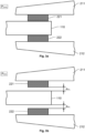
- FIG. 1 we see a schematic representation of rail vehicle 100 containing an electrically operated brake assembly 200 according to one embodiment of the invention.
- the brake assembly 200 contains: a rotating member 110, at least one friction member 221 and 222, a gear assembly 220, an electric motor 230, a force sensor 225, an angular position sensor 237 and a controller 120.
- the rotating member 110 is mechanically linked to a wheel axle 115 of the rail vehicle 100.
- the wheel axle 115 in turn, carries two wheels configured to roll on a respective rail.
- Figure 1 exemplifies one such wheel 105.
- the at least one friction member is here exemplified by 221 and 222 respectively. It should be noted, however, that the arrangement of the at least one friction member and the rotating member may be implemented in alternative ways.
- the rotating member may be a rotating cylinder-shaped part onto which one or more friction members act either from the inside, such as in a conventional drum brake, and/ or from the outside.
- the friction member(s) is/are movable between an engaged position P ENG in which the friction member(s) 221 and 222 contact the rotating member 110, and a disengaged position P DIS in which the rotating member 110 is freely rotatable without contacting any of the friction members 221 or 222.
- the rotating member 110 is a brake disc and the at least one friction member contains two friction members as illustrated in Figures 1 , 3a and 3b by 221 and 222 respectively, which friction members are arranged on a respective one of two pressing members 211 and 212 that are configured to clamp the friction members 221 and 222 respectively against the brake disc 110 and thus perform a braking action in response to a brake command cmd B .
- the gear assembly 220 is arranged to operate mechanically on the friction members 221 and 222, and the electric motor 230 is controllable via a control signal CS to cause the gear assembly 220 to operate on the friction members 221 and 222 to move between the engaged and disengaged positions P ENG and P DIS respectively.
- the force sensor 225 which may for example contain a load cell or a wire strain gauge is configured to produce a pressure signal F indicating a magnitude of a force at which the friction members 221 and 222 contact the rotating member 110.
- the force sensor 225 is contained in the gear assembly 220. This is advantageous because thereby the force sensor 225 may be mechanically protected from external influence.
- the force sensor 225 is instead contained in one or both of first and second bolts B1 and B2 respectively of the gear assembly 220, via which bolts B1 and B2 an output force from the electric motor 230 is conveyed to the friction members 221 and 222.
- the electric motor 230 is designed to produce a rotational force on an output shaft of the electric motor 230, which rotational force is proportional to a drive current being fed into the electric motor 230.
- the controller 120 is further configured to derive the pressure signal F based on the drive current fed into the electric motor 230.
- the force sensor 225 forms an integral part of the electric motor 230 and the controller 120.
- the angular position sensor 237 which may be implemented by means of a tachometer that is configured to produce a pulse-count signal PC where each pulse count reflects a particular angular movement of the output shaft of the electric motor 230.
- a Bevel gear 235 is arranged to connect the output shaft of the electric motor 230 with the gear assembly 220, and the angular position sensor 237 is comprised in the Bevel gear 235.
- the controller 120 is configured to obtain the pressure signal F and the pulse count signal PC. Based thereon, the controller 120 is configured to define a home position for the electric motor 230 as will be explained below.
- FIG. 4 shows a block diagram of the controller 120 according to one embodiment of the invention.
- the controller 120 includes processing circuitry in the form of at least one processor 430 and a memory unit 420, i.e. non-volatile data carrier, storing a computer program 425, which, in turn, contains software for making the at least one processor 430 execute the actions mentioned in this disclosure when the computer program 425 is run on the at least one processor 430.
- processing circuitry in the form of at least one processor 430 and a memory unit 420, i.e. non-volatile data carrier, storing a computer program 425, which, in turn, contains software for making the at least one processor 430 execute the actions mentioned in this disclosure when the computer program 425 is run on the at least one processor 430.
- the force signal F need not be an external signal input to the controller 120. Instead, the force signal F may be obtained internally in the at least one processor 430 based on the drive current fed into the electric motor 230.
- Figures 5a and 5b show graphs illustrating how the at least one friction member, e.g. 221 and 222, is controlled from the idle distance P DIS to the engaged position P ENG according to one embodiment of the invention.
- the idle distance P DIS is the respective distances between each of the friction members 221 and 222 and the rotating member 110
- the engaged position P ENG is where the respective distance between each of the friction members 221 and 222 and the rotating member 110 is zero.
- the home position represents such a positioning of the electric motor 230 that the gear assembly 220 is caused to locate the friction members 221 and 222 at the idle distance d IDL from the rotating member 110.
- the friction members 221 and 222 are located at the idle distance d IDL , the friction members 221 and 222 are moveable to the engaged position P ENG by controlling the electric motor 230 in a forward direction until a first predefined number of pulse counts have been obtained in the controller 120 via the pulse count signal PC.
- Figure 6a shows a graph illustrating how a force F between the friction members 221 and 222 and the rotating member 110 varies over time t
- Figure 7a shows a graph illustrating how the electric motor 230 is controlled over time t by a control signal CS.
- the controller 120 is configured to define the home position by executing the following steps.
- Figure 6b shows a graph illustrating how the force F between the friction members 221 and 222 and the rotating member 110 varies over time t
- Figure 7b shows a graph illustrating how the electric motor 230 is controlled over time t by the control signal CS.
- the controller 120 is configured to execute the below step between the steps (b) and (c) above: Control the friction members 221 and 222 to retract from the rotating member 110 until the pressure signal F falls below a second threshold value F 2 , which is lower than the first threshold value F 1 .
- the controller 120 controls the electric motor 230 to operate on the friction members 221 and 222 in the retreating direction until the second predefined number of pulse counts have been obtained.
- this is assumed to occur at the point in time t 2 , which may or may not be later than t 1 .
- controller 120 is further configured to perform the following:
- controller 120 each time when executing the steps (a) to (c), the controller 120 is instead configured to:
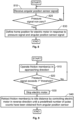
- the brake assembly is presumed to contain: a rotating member mechanically linked to a wheel axle of the rail vehicle, at least one friction member movable between an engaged position in which the at least one friction member contacts the rotating member, and a disengaged position in which the rotating member is freely rotatable without contacting the at least one friction member, a gear assembly arranged to operate mechanically on the at least one friction member, and an electric motor controllable via a control signal and configured to cause the gear assembly to operate on the at least one friction member to move between the engaged and disengaged positions, and which method is implemented in at least one processing circuitry, for instance the above-mentioned at least one processor 430.
- an angular position sensor signal is received, which expresses an angular movement of an output shaft of the electric motor by means of pulse counts, where each pulse count reflects a particular angular movement of the output shaft, i.e. a given increment of a rotation angle of the output shaft.
- a subsequent step 820 checks if a non-zero pressure signal has been obtained, which pressure signal indicates a force at which the friction member(s) contact/s the rotating member. If such a pressure signal has been obtained, the friction member(s) is/are presumed to be in the engaged position, a step 830 follows. Otherwise, the procedure loops back to step 810.
- a home position for the electric motor is defined based on the pulse count signal and the pressure signal.
- the home position may represent such a positioning of the electric motor that the gear assembly is caused to locate the friction member(s) at an idle distance from the rotating member; and when the friction member(s) is/are located at the idle distance, the friction member(s) is/are moveable to the engaged position by controlling the electric motor in a forward direction until a first predefined number of pulse counts have been obtained in the controller via the pulse count signal. Consequently, the home position may be defined as a retraction of the friction members from the rotating member equivalent to a particular number of pulse counts from the engaged position detected in step 820.
- Figure 9 shows a flow diagram of a preferred embodiment of the method according to the invention for defining a home position for the electric motor, at which home position the friction member(s) is/are located at the idle distance from the rotatable member.
- a first step 910 the friction member(s) is/are controlled to move in an approaching direction towards the rotatable member by controlling the electric motor to cause the gear assembly to operate on the friction member(s).
- a following step 920 checks if a pressure signal exceeds a first threshold value, which pressure signal reflects the force at which the friction member(s) contact/s the rotating member. If the pressure signal exceeds the first threshold value, the procedure continues to a step 930. Otherwise, the procedure loops back to step 910.
- step 930 the electric motor is controlled to stop the movement of the friction member(s) in the approaching direction.
- step 949 follows in which the electric motor is controlled to operate on the gear assembly to cause the gear assembly to move the friction member(s) in a retreating direction until a second predefined number of pulse counts have been obtained via the pulse count signal.
- the retreating direction is opposite to the approaching direction defined in step 910.
- All of the process steps, as well as any sub-sequence of steps, described with reference to Figures 8 and 9 may be controlled by means of a programmed processor.
- the embodiments of the invention described above with reference to the drawings comprise processor and processes performed in at least one processor, the invention thus also extends to computer programs, particularly computer programs on or in a carrier, adapted for putting the invention into practice.
- the program may be in the form of source code, object code, a code intermediate source and object code such as in partially compiled form, or in any other form suitable for use in the implementation of the process according to the invention.
- the program may either be a part of an operating system, or be a separate application.
- the carrier may be any entity or device capable of carrying the program.
- the carrier may comprise a storage medium, such as a Flash memory, a ROM (Read Only Memory), for example a DVD (Digital Video/Versatile Disk), a CD (Compact Disc) or a semiconductor ROM, an EPROM (Erasable Programmable Read-Only Memory), an EEPROM (Electrically Erasable Programmable Read-Only Memory), or a magnetic recording medium, for example a floppy disc or hard disc.
- the carrier may be a transmissible carrier such as an electrical or optical signal which may be conveyed via electrical or optical cable or by radio or by other means.
- the carrier When the program is embodied in a signal, which may be conveyed, directly by a cable or other device or means, the carrier may be constituted by such cable or device or means.
- the carrier may be an integrated circuit in which the program is embedded, the integrated circuit being adapted for performing, or for use in the performance of, the relevant processes.
Landscapes
- Engineering & Computer Science (AREA)
- Mechanical Engineering (AREA)
- General Engineering & Computer Science (AREA)
- Transportation (AREA)
- Braking Arrangements (AREA)
- Regulating Braking Force (AREA)
- Braking Systems And Boosters (AREA)
Claims (16)
- Elektrisch betriebene Bremsanordnung (200) für ein Schienenfahrzeug (100), wobei die Bremsanordnung (200) aufweist:ein rotierendes Element (110), das mit einer Radachse (115) des Schienenfahrzeugs (100) mechanisch gekoppelt ist,wenigstens ein Reibungselement (221; 222), das zwischen einer Eingreifposition (PENG), in welcher wenigstens eine Reibungselement (221; 222) das rotierende Element (110) berührt, und einer gelösten Position (PDIS) beweglich ist,, in welcher das rotierende Element (110) frei drehbar ist, ohne das wenigstens eine Reibungselement (221; 222) zu berühren,eine Getriebeanordnung (220), die eingerichtet ist, um auf das wenigstens eine Reibungselement (221; 222) mechanisch einzuwirken, undeinen Elektromotor (230), der über ein Steuersignal (CS) steuerbar ist und konfiguriert ist, um zu bewirken, dass die Getriebeanordnung (220) derart auf das wenigstens eine Reibungselement (221; 222) einwirkt, dass es sich zwischen den Eingreif- und gelösten Positionen (PENG, PDIS) bewegt, wobei die Bremsanordnung (200) aufweist:einen Kraftsensor (225), der konfiguriert ist, um ein Drucksignal (F) zu erzeugen, das einen Betrag einer Kraft angibt, mit der das wenigstens eine Reibungselement (221; 222) das rotierende Element (110) berührt,einen Winkelpositionssensor (237), der konfiguriert ist, um ein Impulszählsignal (PC) zu erzeugen, wobei jede Impulszählung eine bestimmte Winkelbewegung einer Ausgangswelle des Elektromotors (230) widerspiegelt, undeine Steuerung (120), die konfiguriert ist, um das Drucksignal (F) und das Impulszählsignal (PC) zu erhalten und basierend darauf eine Grundposition für den Elektromotor (230) zu definieren,wobei die Grundposition eine derartige Positionierung des Elektromotors (230) darstellt, dass bewirkt wird, dass die Getriebeanordnung (220) das wenigstens eine Reibungselement (221; 222) in einem Leerlaufabstand (dIDL) von dem rotierenden Element (110) anordnet; und wobei das wenigstens eine Reibungselement (221; 222), wenn das wenigstens eine Reibungselement (221; 222) in dem Leerlaufabstand (dIDL) angeordnet ist, in die Eingreifposition (PENG) beweglich ist, indem der Elektromotor (230) in eine Vorwärtsrichtung gesteuert wird, bis in der Steuerung (120) über das Impulszählsignal (PC) eine erste vorgegebene Anzahl von Impulszählungen erhalten wurde,wobei die Steuerung (120) konfiguriert ist, um die Grundposition durch Ausführen der folgenden Schritte zu definieren:(a) Steuern des Elektromotors (120), um zu bewirken, dass die Getriebeanordnung (220) auf das wenigstens eine Reibungselement (221; 222) in einer Annäherungsrichtung einwirkt, wobei das wenigstens eine Reibungselement (221; 222) zu der Eingreifposition (PENG) bewegt wird, wobei die Steuerung des Elektromotors (120) fortgesetzt wird, um zu bewirken, dass die Getriebeanordnung (220) auf das wenigstens eine Reibungselement (221; 222) in der Annäherungsrichtung einwirkt, bis das Drucksignal (F) einen ersten Schwellwert (F1) überschreitet, danach:(b) Steuern des Elektromotors (230), dass er stoppt, und anschließend(c) Zurückziehen des wenigstens einen Reibungselements (221; 222) von dem rotierenden Element (110) zu dem Leerlaufabstand (dIDL) durch Steuern des Elektromotors (230), so dass er auf die Getriebeanordnung (220) einwirkt, um zu bewirken, dass die Getriebeanordnung (220) das wenigstens eine Reibungselement (221; 222) in einer Rückzugsrichtung bewegt, bis in der Steuerung (120) über die Impulszählung eine zweite vorgegebene Anzahl von Impulszählungen erhalten wurde, wobei die Rückzugsrichtung entgegengesetzt zu der Annäherungsrichtung ist,dadurch gekennzeichnet, dass die Steuerung (120) zwischen den Schritten (b) und (c) konfiguriert ist, um:
das wenigstens eine Reibungselement (221; 222) von dem rotierenden Element (110) zurückzuziehen, bis das Drucksignal (F) unter einen zweiten Schwellwert (F2), der niedriger als der erste Schwellwert (F1) ist, fällt. - Bremsanordnung (200) nach Anspruch 1, wobei die Steuerung (120) jedes Mal, wenn die Schritte (a) bis (c) ausgeführt werden, konfiguriert ist, um:eine erste Anzahl von Impulszählungen aufzuzeichnen, die über das Impulszählsignal (PC) erhalten wird, während der Schritt (a) ausgeführt wird,die aufgezeichnete erste Anzahl von Impulszählungen mit der zweiten vorgegebenen Anzahl von Impulszählungen zu vergleichen, wenn die letztere Anzahl niedriger ist,eine Abnutzungszählung um eine Differenz zwischen den ersten und zweiten Anzahlen zu erhöhen, und, wenn die Abnutzungszählung eine Schwellwertzählung überschreitet,einen Wartungsalarm in Bezug auf das wenigstens eine Reibungselement (221; 222) auszulösen.
- Bremsanordnung (200) nach Anspruch 1, wobei die Steuerung (120) konfiguriert ist, um jedes Mal, wenn die Schritte (a) bis (c) ausgeführt werden:den Elektromotor (230) derart zu steuern, dass er auf die Getriebeanordnung (220) einwirkt, um zu bewirken, dass die Getriebeanordnung (220) das wenigstens eine Reibungselement (221; 222) in der Rückzugsrichtung von dem rotierenden Element (110) zurückzieht, bis das Drucksignal (F) unter einen negativen Schwellwert, der einen maximalen Rückzug des wenigstens einen Reibungselements (221; 222) bezeichnet, fällt,eine erste Anzahl von über das Impulszählsignal (PC) erhaltenen Impulszählungen aufzuzeichnen, während der Schritt (a) ausgeführt wird, und, wenn die erste Anzahl von Impulszählungen eine Schwellwertzählung überschreitet,einen Wartungsalarm in Bezug auf das wenigstens eine Reibungselement (221; 222) auszulösen.
- Bremsanordnung (200) nach einem der vorhergehenden Ansprüche, wobeider Elektromotor (230) konfiguriert ist, um eine Drehkraft auf einer Ausgangswelle des Elektromotors (230) zu erzeugen, wobei diese Drehkraft proportional zu einem Antriebsstrom ist, der in den Elektromotor (230) eingespeist wird, undwobei die Steuerung (120) konfiguriert ist, um das Drucksignal (F) basierend auf dem in den Elektromotor (230) eingespeisten Strom abzuleiten.
- Bremsanordnung (200) nach einem der Ansprüche 1 bis 3, wobei der Kraftsensor (225) in der Getriebeanordnung (220) enthalten ist.
- Bremsanordnung (200) nach Anspruch 5, wobei der Kraftsensor (225) eine Kraftmessdose oder einen Dehnungsmessstreifen aufweist.
- Bremsanordnung (200) nach einem der vorhergehenden Ansprüche, wobei der Elektromotor (230) ein Schrittmotor, der den Winkelpositionssensor aufweist, ist.
- Bremsanordnung (200) nach einem der Ansprüche 1 bis 6, wobei der Winkelpositionssensor (237) eine von dem Elektromotor (230) getrennte Komponente ist.
- Bremsanordnung (200) nach Anspruch 8, wobei der Winkelpositionssensor (237) in einem Kegelradgetriebe (235) enthalten ist, das eingerichtet ist, um die Ausgangswelle des Elektromotors (230) mit der Getriebeanordnung (220) zu verbinden.
- Bremsanordnung (200) nach einem der vorhergehenden Ansprüche, wobei das rotierende Element (110) eine Bremsscheibe ist und das wenigstens eine Reibungselement (221; 222) zwei Reibungselemente aufweist, die auf einem jeweiligen von zwei Druckelementen (211; 212) angeordnet sind, welche konfiguriert sind, um die Reibungselemente (221; 222) gegen die Bremsscheibe (110) zu spannen, um ansprechend auf einen Bremsbefehl (cmdB) eine Bremstätigkeit durchzuführen.
- Computerimplementiertes Verfahren zur Steuerung einer elektrisch betriebenen Bremsanordnung (200) für ein Schienenfahrzeug, wobei die Bremsanordnung (200) aufweist: ein rotierendes Element (110), das mit einer Radachse (115) des Schienenfahrzeugs (100) mechanisch gekoppelt ist, wenigstens ein Reibungselement (221; 222), das zwischen einer Eingreifposition (PENG), in welcher wenigstens eine Reibungselement (221; 222) das rotierende Element (110) berührt, und einer gelösten Position (PDIS) beweglich ist, in welcher das rotierende Element (110) frei drehbar ist, ohne das wenigstens eine Reibungselement (221; 222) zu berühren, eine Getriebeanordnung (220), die eingerichtet ist, um auf das wenigstens eine Reibungselement (221; 222) mechanisch einzuwirken, und einen Elektromotor (230), der über ein Steuersignal (CS) steuerbar ist und konfiguriert ist, um zu bewirken, dass die Getriebeanordnung (220) derart auf das wenigstens eine Reibungselement (221; 222) einwirkt, dass es sich zwischen den Eingreif- und gelösten Positionen (PENG, PDIS) bewegt, wobei das Verfahren in wenigstens einer Verarbeitungsschaltung (430) implementiert ist und die Bremsanordnung ferner aufweist: einen Kraftsensor (225), der konfiguriert ist, um ein Drucksignal (F) zu erzeugen, das einen Betrag einer Kraft angibt, mit der das wenigstens eine Reibungselement (221; 222) das rotierende Element (110) berührt, und einen Winkelpositionssensor (237), der konfiguriert ist, um ein Impulszählsignal (PC) zu erzeugen, wobei jede Impulszählung eine bestimmte Winkelbewegung einer Ausgangswelle des Elektromotors (230) widerspiegelt, und wobei das Verfahren aufweist:
Erhalten der Druck- und Impulszählsignale (F; PC) und basierend darauf:Definieren einer Grundposition für den Elektromotor (230), wobei die Grundposition eine derartige Positionierung des Elektromotors (230) darstellt, dass bewirkt wird, dass die Getriebeanordnung (220) das wenigstens eine Reibungselement (221; 222) in einem Leerlaufabstand (dIDL) von dem rotierenden Element (110) anordnet; und wobei das wenigstens eine Reibungselement (221; 222), wenn das wenigstens eine Reibungselement (221; 222) in dem Leerlaufabstand (dIDL) angeordnet ist, in die Eingreifposition (PENG) beweglich ist, indem der Elektromotor (230) in eine Vorwärtsrichtung gesteuert wird, bis in der Steuerung (120) über das Impulszählsignal (PC) eine erste vorgegebene Anzahl von Impulszählungen erhalten wurde,was das Definieren der Grundposition durch Ausführen der folgenden Schritte aufweist:(a) Steuern des Elektromotors (120), um zu bewirken, dass die Getriebeanordnung (220) auf das wenigstens eine Reibungselement (221; 222) in einer Annäherungsrichtung einwirkt, wobei das wenigstens eine Reibungselement (221; 222) zu der Eingreifposition (PENG) bewegt wird, dass die Steuerung des Elektromotors (120) fortgesetzt wird, um zu bewirken, dass die Getriebeanordnung (220) auf das wenigstens eine Reibungselement (221; 222) in der Annäherungsrichtung einwirkt, bis das Drucksignal (F) einen ersten Schwellwert (F1) überschreitet, danach:(b) Steuern des Elektromotors (230), dass er stoppt, und anschließend(c) Zurückziehen des wenigstens einen Reibungselements (221; 222) von dem rotierenden Element (110) zu dem Leerlaufabstand (dIDL) durch Steuern des Elektromotors (230), so dass er auf die Getriebeanordnung (220) einwirkt, um zu bewirken, dass die Getriebeanordnung (220) das wenigstens eine Reibungselement (221; 222) in einer Rückzugsrichtung bewegt, bis in der Steuerung (120) über die Impulszählung eine zweite vorgegebene Anzahl von Impulszählungen erhalten wurde, wobei die Rückzugsrichtung entgegengesetzt zu der Annäherungsrichtung ist,dadurch gekennzeichnet, dass das Verfahren zwischen den Schritten (b) und (c) aufweist:
Zurückziehen des wenigstens einen Reibungselements (221; 222) von dem rotierenden Element (110), bis das Drucksignal (F) unter einen zweiten Schwellwert (F2), der niedriger als der erste Schwellwert (F1) ist, fällt. - Verfahren nach Anspruch 11, wobei das Verfahren jedes Mal, wenn die Schritte (a) bis (c) ausgeführt werden, aufweist:Aufzeichnen einer ersten Anzahl von Impulszählungen, die über das Impulszählsignal (PC) erhalten wird, während der Schritt (a) ausgeführt wird,Vergleichen der aufgezeichneten ersten Anzahl von Impulszählungen mit der zweiten vorgegebenen Anzahl von Impulszählungen, wenn die letztere Anzahl niedriger ist,Erhöhen einer Abnutzungszählung um eine Differenz zwischen den ersten und zweiten Anzahlen, und, wenn die Abnutzungszählung eine Schwellwertzählung überschreitet,Auslösen eines Wartungsalarms in Bezug auf das wenigstens eine Reibungselement (221; 222).
- Verfahren nach Anspruch 11, wobei das Verfahren ferner jedes Mal, wenn die Schritte (a) bis (c) ausgeführt werden, aufweist:Steuern des Elektromotors (230) derart, dass er auf die Getriebeanordnung (220) einwirkt, um zu bewirken, dass die Getriebeanordnung (220) das wenigstens eine Reibungselement (221; 222) in der Rückzugsrichtung von dem rotierenden Element (110) zurückzieht, bis das Drucksignal (F) unter einen negativen Schwellwert, der einen maximalen Rückzug des wenigstens einen Reibungselements (221; 222) bezeichnet, fällt,Aufzeichnen einer ersten Anzahl von über das Impulszählsignal (PC) erhaltenen Impulszählungen, während der Schritt (a) ausgeführt wird, und, wenn die erste Anzahl von Impulszählungen eine Schwellwertzählung überschreitet,Auslösen eines Wartungsalarms in Bezug auf das wenigstens eine Reibungselement (221; 222).
- Verfahren nach einem der Ansprüche 11 bis 13, wobei der Elektromotor (230) konfiguriert ist, um eine Drehkraft auf einer Ausgangswelle des Elektromotors (230) zu erzeugen, wobei diese Drehkraft proportional zu einem Antriebsstrom ist, der in den Elektromotor (230) eingespeist wird, und wobei das Verfahren aufweist:
Ableiten des Drucksignals (F) basierend auf dem in den Elektromotor 230) eingespeisten Stroms. - Computerprogramm (425), das in einen nichtflüchtigen Datenträger (420) ladbar ist, der kommunikationsfähig mit wenigstens nach einem Prozessor (430) verbunden ist, wobei das Computerprogramm (425) Software zum Ausführen des Verfahrens nach einem der Ansprüche 11 bis 14 aufweist, wenn das Computerprogramm (425) auf dem wenigstens einen Prozessor (430) ausgeführt wird.
- Nichtflüchtiger Datenträger (420), der das Computerprogramm (425) nach Anspruch 15 enthält.
Priority Applications (6)
| Application Number | Priority Date | Filing Date | Title |
|---|---|---|---|
| EP24192801.9A EP4434833A3 (de) | 2022-08-24 | 2022-08-24 | Elektrisch betätigte bremsanordnung, computerimplementiertes verfahren zur steuerung einer elektrisch betätigten bremsanordnung, computerprogramm und nichtflüchtiger datenträger |
| EP24192798.7A EP4434832A3 (de) | 2022-08-24 | 2022-08-24 | Elektrisch betätigte bremsanordnung, computerimplementiertes verfahren zur steuerung einer elektrisch betätigten bremsanordnung, computerprogramm und nichtflüchtiger datenträger |
| ES22191873T ES3029332T3 (en) | 2022-08-24 | 2022-08-24 | Electrically operated brake assembly, computer-implemented method for controlling an electrically operated brake assembly, computer program and non-volatile data carrier |
| EP22191873.3A EP4328103B1 (de) | 2022-08-24 | 2022-08-24 | Elektrisch betriebene bremsanordnung, computerimplementiertes verfahren zur steuerung einer elektrisch betriebenen bremsanordnung, computerprogramm und nichtflüchtiger datenträger |
| CN202380054070.2A CN119630566A (zh) | 2022-08-24 | 2023-08-07 | 电动制动组件、用于控制电动制动组件的计算机实现方法、计算机程序和非易失性数据载体 |
| PCT/EP2023/071815 WO2024041877A1 (en) | 2022-08-24 | 2023-08-07 | Electrically operated brake assembly, computer-implemented method for controlling an electrically operated brake assembly, computer program and non-volatile data carrier |
Applications Claiming Priority (1)
| Application Number | Priority Date | Filing Date | Title |
|---|---|---|---|
| EP22191873.3A EP4328103B1 (de) | 2022-08-24 | 2022-08-24 | Elektrisch betriebene bremsanordnung, computerimplementiertes verfahren zur steuerung einer elektrisch betriebenen bremsanordnung, computerprogramm und nichtflüchtiger datenträger |
Related Child Applications (4)
| Application Number | Title | Priority Date | Filing Date |
|---|---|---|---|
| EP24192801.9A Division EP4434833A3 (de) | 2022-08-24 | 2022-08-24 | Elektrisch betätigte bremsanordnung, computerimplementiertes verfahren zur steuerung einer elektrisch betätigten bremsanordnung, computerprogramm und nichtflüchtiger datenträger |
| EP24192801.9A Division-Into EP4434833A3 (de) | 2022-08-24 | 2022-08-24 | Elektrisch betätigte bremsanordnung, computerimplementiertes verfahren zur steuerung einer elektrisch betätigten bremsanordnung, computerprogramm und nichtflüchtiger datenträger |
| EP24192798.7A Division EP4434832A3 (de) | 2022-08-24 | 2022-08-24 | Elektrisch betätigte bremsanordnung, computerimplementiertes verfahren zur steuerung einer elektrisch betätigten bremsanordnung, computerprogramm und nichtflüchtiger datenträger |
| EP24192798.7A Division-Into EP4434832A3 (de) | 2022-08-24 | 2022-08-24 | Elektrisch betätigte bremsanordnung, computerimplementiertes verfahren zur steuerung einer elektrisch betätigten bremsanordnung, computerprogramm und nichtflüchtiger datenträger |
Publications (3)
| Publication Number | Publication Date |
|---|---|
| EP4328103A1 EP4328103A1 (de) | 2024-02-28 |
| EP4328103B1 true EP4328103B1 (de) | 2025-04-23 |
| EP4328103C0 EP4328103C0 (de) | 2025-04-23 |
Family
ID=83059114
Family Applications (3)
| Application Number | Title | Priority Date | Filing Date |
|---|---|---|---|
| EP22191873.3A Active EP4328103B1 (de) | 2022-08-24 | 2022-08-24 | Elektrisch betriebene bremsanordnung, computerimplementiertes verfahren zur steuerung einer elektrisch betriebenen bremsanordnung, computerprogramm und nichtflüchtiger datenträger |
| EP24192801.9A Withdrawn EP4434833A3 (de) | 2022-08-24 | 2022-08-24 | Elektrisch betätigte bremsanordnung, computerimplementiertes verfahren zur steuerung einer elektrisch betätigten bremsanordnung, computerprogramm und nichtflüchtiger datenträger |
| EP24192798.7A Withdrawn EP4434832A3 (de) | 2022-08-24 | 2022-08-24 | Elektrisch betätigte bremsanordnung, computerimplementiertes verfahren zur steuerung einer elektrisch betätigten bremsanordnung, computerprogramm und nichtflüchtiger datenträger |
Family Applications After (2)
| Application Number | Title | Priority Date | Filing Date |
|---|---|---|---|
| EP24192801.9A Withdrawn EP4434833A3 (de) | 2022-08-24 | 2022-08-24 | Elektrisch betätigte bremsanordnung, computerimplementiertes verfahren zur steuerung einer elektrisch betätigten bremsanordnung, computerprogramm und nichtflüchtiger datenträger |
| EP24192798.7A Withdrawn EP4434832A3 (de) | 2022-08-24 | 2022-08-24 | Elektrisch betätigte bremsanordnung, computerimplementiertes verfahren zur steuerung einer elektrisch betätigten bremsanordnung, computerprogramm und nichtflüchtiger datenträger |
Country Status (4)
| Country | Link |
|---|---|
| EP (3) | EP4328103B1 (de) |
| CN (1) | CN119630566A (de) |
| ES (1) | ES3029332T3 (de) |
| WO (1) | WO2024041877A1 (de) |
Family Cites Families (8)
| Publication number | Priority date | Publication date | Assignee | Title |
|---|---|---|---|---|
| JP2006206051A (ja) * | 1997-10-07 | 2006-08-10 | Toyota Motor Corp | ブレーキシステム |
| DE10106377C2 (de) * | 2000-12-19 | 2003-04-17 | Knorr Bremse Systeme | Elektromechanische Bremszuspanneinrichtung |
| US6896106B2 (en) | 2002-10-02 | 2005-05-24 | Arvinmeritor Technology, Llc | Method and assembly for automatic slack adjustment of an electric brake actuator |
| WO2009044908A2 (en) * | 2007-10-04 | 2009-04-09 | Toyota Jidosha Kabushiki Kaisha | Parking brake system |
| JP5378278B2 (ja) * | 2010-03-24 | 2013-12-25 | 曙ブレーキ工業株式会社 | 電動式パーキング機構付ブレーキ装置 |
| JP5737500B2 (ja) * | 2011-01-31 | 2015-06-17 | 日立オートモティブシステムズ株式会社 | 電動ブレーキ装置 |
| WO2018110687A1 (ja) * | 2016-12-15 | 2018-06-21 | 株式会社アドヴィックス | 車両の電動制動装置 |
| IT202000016912A1 (it) * | 2020-07-13 | 2022-01-13 | Faiveley Transport Italia Spa | Attuatore elettromeccanico di frenatura per un veicolo ferroviario e sistema di frenatura |
-
2022
- 2022-08-24 EP EP22191873.3A patent/EP4328103B1/de active Active
- 2022-08-24 EP EP24192801.9A patent/EP4434833A3/de not_active Withdrawn
- 2022-08-24 ES ES22191873T patent/ES3029332T3/es active Active
- 2022-08-24 EP EP24192798.7A patent/EP4434832A3/de not_active Withdrawn
-
2023
- 2023-08-07 WO PCT/EP2023/071815 patent/WO2024041877A1/en not_active Ceased
- 2023-08-07 CN CN202380054070.2A patent/CN119630566A/zh active Pending
Also Published As
| Publication number | Publication date |
|---|---|
| EP4434832A3 (de) | 2024-11-13 |
| CN119630566A (zh) | 2025-03-14 |
| EP4434833A2 (de) | 2024-09-25 |
| EP4434833A3 (de) | 2024-11-06 |
| WO2024041877A1 (en) | 2024-02-29 |
| EP4328103A1 (de) | 2024-02-28 |
| EP4328103C0 (de) | 2025-04-23 |
| EP4434832A2 (de) | 2024-09-25 |
| ES3029332T3 (en) | 2025-06-24 |
Similar Documents
| Publication | Publication Date | Title |
|---|---|---|
| CN110053597B (zh) | 电动制动装置系统 | |
| KR101836628B1 (ko) | 전동식 브레이크 장치 및 그 제어 방법 | |
| CN111699119B (zh) | 电动制动器及控制装置 | |
| CN107953878B (zh) | 电子驻车制动系统及其控制方法 | |
| US9677632B2 (en) | Electromechanically actuatable brake and method for operating an electromechanically actuatable brake | |
| KR101981479B1 (ko) | 전자식 파킹 브레이크의 고장 감지 방법 및 장치 | |
| US6626269B2 (en) | Zero drag disc brake with anti-knock-back device | |
| US12158187B2 (en) | Electromechanical brake system and control method thereof | |
| EP4328103B1 (de) | Elektrisch betriebene bremsanordnung, computerimplementiertes verfahren zur steuerung einer elektrisch betriebenen bremsanordnung, computerprogramm und nichtflüchtiger datenträger | |
| US6896106B2 (en) | Method and assembly for automatic slack adjustment of an electric brake actuator | |
| US11577711B2 (en) | Method of controlling a brake for service operation | |
| KR20220084689A (ko) | 전동 드럼 브레이크 시스템 및 그 제어방법 | |
| JP2010203561A (ja) | 電動ブレーキ | |
| EP4663490A1 (de) | Bremssystem für ein schienenfahrzeug, computerimplementiertes verfahren, computerprogramm und nichtflüchtiger datenträger | |
| EP4245620A1 (de) | Bremssystem, computerimplementiertes verfahren zur steuerung eines bremssystems eines schienenfahrzeugs, computerprogramm und nichtflüchtiger datenträger | |
| JP6927921B2 (ja) | 電動ブレーキ装置システム | |
| KR102934272B1 (ko) | 전자식 주차 브레이크 | |
| JP5416817B2 (ja) | 電動ブレーキ | |
| US12493286B2 (en) | System and computer-implemented method for controlling a rotary milking parlor arrangement and computer program | |
| JP5296908B2 (ja) | 電動ブレーキ | |
| EP4474233A1 (de) | Bremsaktuator, computerimplementiertes verfahren, computerprogramm, nichtflüchtiger datenträger und bremssystem für ein schienenfahrzeug | |
| US20240052902A1 (en) | Method and device for determining the wear of a brake | |
| KR20260041655A (ko) | 전기기계식 브레이크 어셈블리 및 이를 제어하는 방법과 컴퓨터 판독 가능한 기록 매체 | |
| CN118220078A (zh) | 一种电子机械制动器驻车控制方法 | |
| KR20260055858A (ko) | 브레이크 장치 및 그 제어방법 |
Legal Events
| Date | Code | Title | Description |
|---|---|---|---|
| PUAI | Public reference made under article 153(3) epc to a published international application that has entered the european phase |
Free format text: ORIGINAL CODE: 0009012 |
|
| STAA | Information on the status of an ep patent application or granted ep patent |
Free format text: STATUS: THE APPLICATION HAS BEEN PUBLISHED |
|
| AK | Designated contracting states |
Kind code of ref document: A1 Designated state(s): AL AT BE BG CH CY CZ DE DK EE ES FI FR GB GR HR HU IE IS IT LI LT LU LV MC MK MT NL NO PL PT RO RS SE SI SK SM TR |
|
| STAA | Information on the status of an ep patent application or granted ep patent |
Free format text: STATUS: REQUEST FOR EXAMINATION WAS MADE |
|
| 17P | Request for examination filed |
Effective date: 20240718 |
|
| RBV | Designated contracting states (corrected) |
Designated state(s): AL AT BE BG CH CY CZ DE DK EE ES FI FR GB GR HR HU IE IS IT LI LT LU LV MC MK MT NL NO PL PT RO RS SE SI SK SM TR |
|
| GRAP | Despatch of communication of intention to grant a patent |
Free format text: ORIGINAL CODE: EPIDOSNIGR1 |
|
| STAA | Information on the status of an ep patent application or granted ep patent |
Free format text: STATUS: GRANT OF PATENT IS INTENDED |
|
| GRAS | Grant fee paid |
Free format text: ORIGINAL CODE: EPIDOSNIGR3 |
|
| GRAA | (expected) grant |
Free format text: ORIGINAL CODE: 0009210 |
|
| STAA | Information on the status of an ep patent application or granted ep patent |
Free format text: STATUS: THE PATENT HAS BEEN GRANTED |
|
| INTG | Intention to grant announced |
Effective date: 20250227 |
|
| AK | Designated contracting states |
Kind code of ref document: B1 Designated state(s): AL AT BE BG CH CY CZ DE DK EE ES FI FR GB GR HR HU IE IS IT LI LT LU LV MC MK MT NL NO PL PT RO RS SE SI SK SM TR |
|
| REG | Reference to a national code |
Ref country code: GB Ref legal event code: FG4D |
|
| REG | Reference to a national code |
Ref country code: CH Ref legal event code: EP |
|
| REG | Reference to a national code |
Ref country code: IE Ref legal event code: FG4D |
|
| U01 | Request for unitary effect filed |
Effective date: 20250423 |
|
| U07 | Unitary effect registered |
Designated state(s): AT BE BG DE DK EE FI FR IT LT LU LV MT NL PT RO SE SI Effective date: 20250428 |
|
| REG | Reference to a national code |
Ref country code: ES Ref legal event code: FG2A Ref document number: 3029332 Country of ref document: ES Kind code of ref document: T3 Effective date: 20250624 |
|
| U20 | Renewal fee for the european patent with unitary effect paid |
Year of fee payment: 4 Effective date: 20250815 |
|
| PGFP | Annual fee paid to national office [announced via postgrant information from national office to epo] |
Ref country code: ES Payment date: 20250910 Year of fee payment: 4 |
|
| PG25 | Lapsed in a contracting state [announced via postgrant information from national office to epo] |
Ref country code: NO Free format text: LAPSE BECAUSE OF FAILURE TO SUBMIT A TRANSLATION OF THE DESCRIPTION OR TO PAY THE FEE WITHIN THE PRESCRIBED TIME-LIMIT Effective date: 20250723 Ref country code: GR Free format text: LAPSE BECAUSE OF FAILURE TO SUBMIT A TRANSLATION OF THE DESCRIPTION OR TO PAY THE FEE WITHIN THE PRESCRIBED TIME-LIMIT Effective date: 20250724 |
|
| PG25 | Lapsed in a contracting state [announced via postgrant information from national office to epo] |
Ref country code: PL Free format text: LAPSE BECAUSE OF FAILURE TO SUBMIT A TRANSLATION OF THE DESCRIPTION OR TO PAY THE FEE WITHIN THE PRESCRIBED TIME-LIMIT Effective date: 20250423 |
|
| PG25 | Lapsed in a contracting state [announced via postgrant information from national office to epo] |
Ref country code: HR Free format text: LAPSE BECAUSE OF FAILURE TO SUBMIT A TRANSLATION OF THE DESCRIPTION OR TO PAY THE FEE WITHIN THE PRESCRIBED TIME-LIMIT Effective date: 20250423 |
|
| PG25 | Lapsed in a contracting state [announced via postgrant information from national office to epo] |
Ref country code: RS Free format text: LAPSE BECAUSE OF FAILURE TO SUBMIT A TRANSLATION OF THE DESCRIPTION OR TO PAY THE FEE WITHIN THE PRESCRIBED TIME-LIMIT Effective date: 20250723 |
|
| PG25 | Lapsed in a contracting state [announced via postgrant information from national office to epo] |
Ref country code: IS Free format text: LAPSE BECAUSE OF FAILURE TO SUBMIT A TRANSLATION OF THE DESCRIPTION OR TO PAY THE FEE WITHIN THE PRESCRIBED TIME-LIMIT Effective date: 20250823 |
|
| PG25 | Lapsed in a contracting state [announced via postgrant information from national office to epo] |
Ref country code: SM Free format text: LAPSE BECAUSE OF FAILURE TO SUBMIT A TRANSLATION OF THE DESCRIPTION OR TO PAY THE FEE WITHIN THE PRESCRIBED TIME-LIMIT Effective date: 20250423 |
|
| PG25 | Lapsed in a contracting state [announced via postgrant information from national office to epo] |
Ref country code: CZ Free format text: LAPSE BECAUSE OF FAILURE TO SUBMIT A TRANSLATION OF THE DESCRIPTION OR TO PAY THE FEE WITHIN THE PRESCRIBED TIME-LIMIT Effective date: 20250423 |
|
| PG25 | Lapsed in a contracting state [announced via postgrant information from national office to epo] |
Ref country code: SK Free format text: LAPSE BECAUSE OF FAILURE TO SUBMIT A TRANSLATION OF THE DESCRIPTION OR TO PAY THE FEE WITHIN THE PRESCRIBED TIME-LIMIT Effective date: 20250423 |
|
| PLBE | No opposition filed within time limit |
Free format text: ORIGINAL CODE: 0009261 |
|
| STAA | Information on the status of an ep patent application or granted ep patent |
Free format text: STATUS: NO OPPOSITION FILED WITHIN TIME LIMIT |
|
| REG | Reference to a national code |
Ref country code: CH Ref legal event code: L10 Free format text: ST27 STATUS EVENT CODE: U-0-0-L10-L00 (AS PROVIDED BY THE NATIONAL OFFICE) Effective date: 20260304 |
|
| REG | Reference to a national code |
Ref country code: CH Ref legal event code: H13 Free format text: ST27 STATUS EVENT CODE: U-0-0-H10-H13 (AS PROVIDED BY THE NATIONAL OFFICE) Effective date: 20260324 |
|
| PG25 | Lapsed in a contracting state [announced via postgrant information from national office to epo] |
Ref country code: MC Free format text: LAPSE BECAUSE OF FAILURE TO SUBMIT A TRANSLATION OF THE DESCRIPTION OR TO PAY THE FEE WITHIN THE PRESCRIBED TIME-LIMIT Effective date: 20250423 |
|
| 26N | No opposition filed |
Effective date: 20260126 |